

Page 1
Implementing an 8-Bit Asynchronous Interface
with FX2LP
AN6077
Author: Sonia Gandhi
Associated Project: No
Associated Part Family: CY7C68013A
GET FREE SAMPLES HERE
Software Version: None
Associated Application Notes: None
Application Note Abstract
This application note discusses how to configure the General Programmable Interface (GPIF) and slave FIFOs of the EZ-U SB
FX2LP™ to implement an 8-bit asynchronous interface. The GPIF is a programmable 8 or 16-bit parallel interface that reduce s
system costs by providing a glueless interface between the EZ-USB FX2LP and different types of external peripherals. The
GPIF allows the EZ-USB FX2LP to perform local bus mastering to external peripherals implementing a wide variety of protocols.
For example, EIDE/ATAPI, printer parallel port (IEEE P1284), Utopia, and other interfaces are supported using the GPIF block
of the EZ-USB FX2LP. In this example, it masters the slave FIFO interface of another EZ-USB FX2LP.
This implementation uses the GPIF Designer (an utility Cypress provides to create GPIF waveform descriptors) to design the
application specific physical layer. The firmware is based on the Cypress EZ-USB FX2LP firmware ‘frameworks’. A hardware
setup of two back-to-back EZ-USB FX2LP boards is also used, one acting as a master and another as a slave. Familiarity with
the EZ-USB FX2LP development kit, examples and documentation on the development kit CD-ROM, and chapters 9 (EZ-USB
FX2LP Slave FIFOs) and 10 (GPIF) of the EZ-USB FX2LP Technical Reference Manual is assumed
.
Introduction
The objective of this application note is to:
■ Demonstrate a glueless interface to an 8-bit peripheral
data bus (the FIFO of a slave EZ-USB FX2LP).
■ Use EZ-USB FX2LP to transfer data to and from the pe-
ripheral (slave EZ-USB FX2LP) and the USB host.
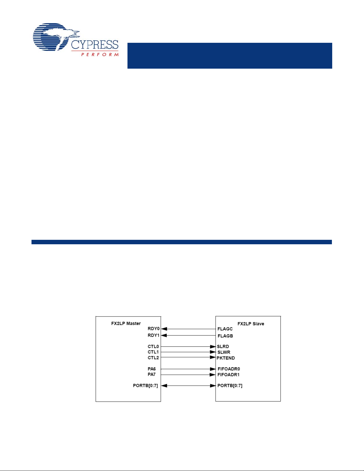
Figure 1. Hardware Connection Diagram
This application note discusses the necessary hardware connections, internal register settings, and 8051 firmware implemented to execute data transactions over the interface and
across the USB bus.
February 19, 2008 Document No. 001-15342 Rev. ** 1
[+] Feedback
Page 2

AN6077
GPIF Master Pin Descriptions
The GPIF pin names, descriptions, and their uses are discussed in this section.
RDYn Inputs
RDY[5:0] are ‘ready’ inputs that can be sampled and allow a
transaction to wait (inserting wait states), continue, or repeat
until the signal is at the appropriate level. This implementation uses RDY0 and RDY1 to control data flow.
RDY0 is tied to FLAGC (EP2 Empty Flag) of the slave and
RDY1 is tied to FLAGB (EP6 Full Flag) of the slave.
Other RDY inputs may be used in the application for additional debug status information.
CTLx Outputs
CTL[5:0] are programmable control outputs that are used as
strobes, read/write lines, or other outputs.
CTL0, CTL1 and CTL2 are used in this application.
CTL0 is tied to SLRD of the slave.
CTL1 is tied to SLWR of the slave.
CTL2 is tied to PKTEND of the slave.
FD[0:7]
This implementation has an 8-bit data bus. PORTB[0:7]
serves as the data bus on both the master and the slave.
PORTA[6:7]
PA6 and PA7 are tied to FIFOADR0 and FIFOADR1 of the
slave. These are used to drive the address of the FIFO being
accessed by the master.
Slave FIFO Pin Descriptions
The slave FIFO pin names, descriptions, and their uses are
discussed in this section.
SLRD
SLRD is the Slave Read line for the FIFO. SLRD acts as the
read strobe for the slave. CTL0 of the master provides the
strobe.
SLWR
SLWR is the Slave Write line for the FIFO. SLWR acts as the
write strobe for the slave. CTL1 of the master provides the
strobe.
SLOE
In this implementation SLOE is tied to SLRD.
FD[0:7]
This is Port B, which is configured as the 8-bit data bus. If the
WORDWIDE bit of the IFCONFIG regi ster is set, then port D
is configured to be FD[8:15]. This implementation has an 8-bit
interface.
FLAGA/FLAGB/FLAGC/FLAGD
FLAGC is used to indicate the state of ‘emptiness’ of the endpoint 2 FIFO of the slave. FLAGB is used to indicate the state
of ‘fullness’ of the endpoint 6 FIFO of the slave.
FLAGA and FLAGD are not used in this implementation.
FIFOADR[0:1]
The master selects one of the four slave FIFOs using the
FIFOADR pins, and then drives the 8-bit FIFO data using the
SLRD (Slave Read) and SLWR (Slave Write) signals.
PKTEND
PKTEND is used to dispatch a short (less than the maximum
packet size) IN packet to the USB. In this im ple ment a tion, it is
tied to CTL2 of the master EZ-USB FX2LP.
Creating GPIF Waveforms
This section describes the parameters to create a waveform
and includes figures for graphical clarity. Example code is
also included.
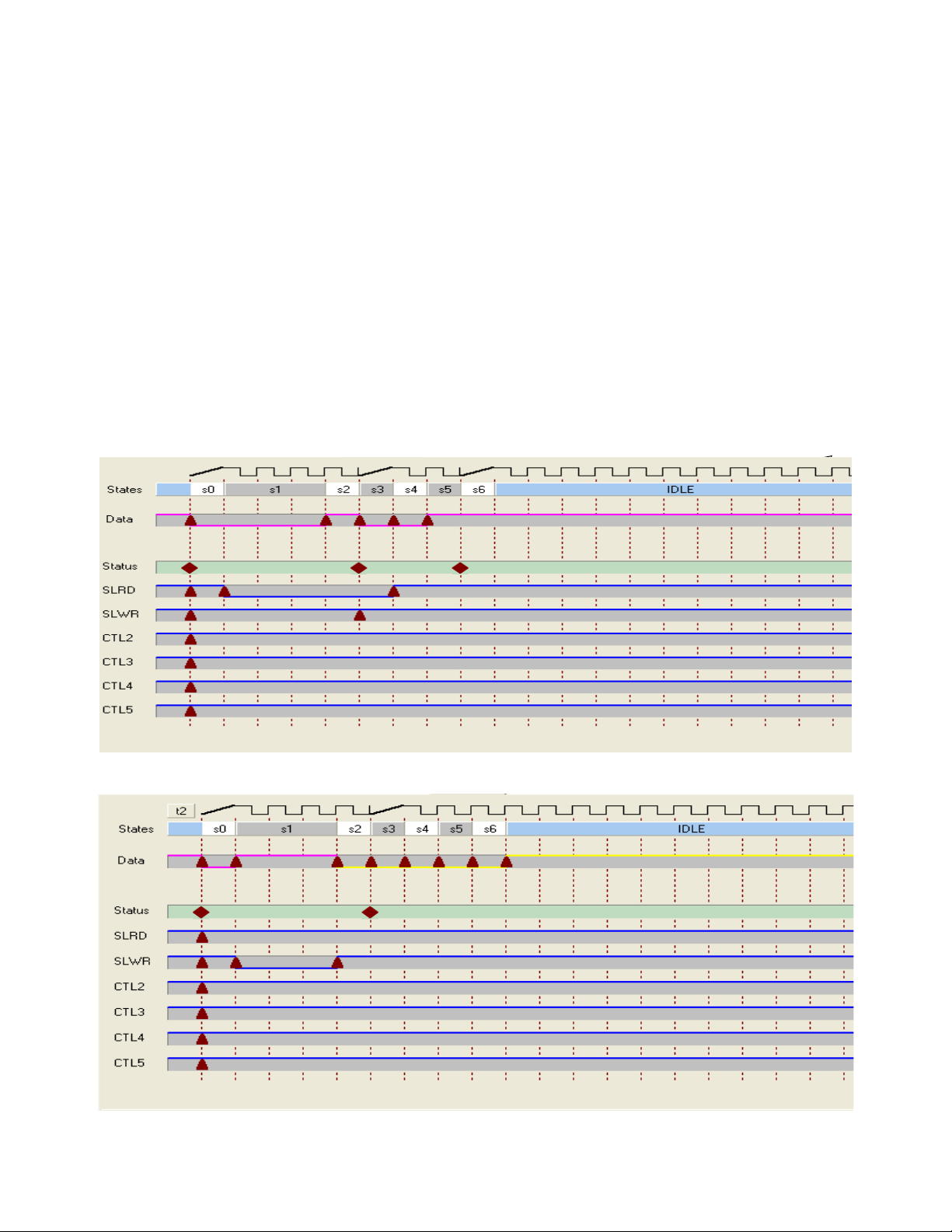
FIFORD
When creating the FIFORD waveform the following timing
parameters must be met.
tRD
tRD
tXFLG - SLRD to FLAGS Output Propagation Delay =
tXFD - SLRD to FIFO Data Output Propagation Delay =
tOE
tOE
This results in the following sequence:
s0 Sample the empty flag of the peripheral. If the periph-
s1 Assert the SLRD strobe and wait for three cycles to
s2 Sample the data bus.
s3 Branch to IDLE.
- SLRD Pulse Width LOW = 50 ns (minimum)
pwl
- SLRD Pulse Width HIGH = 50 ns (minimum)
pwh
70 ns (maximum)
15 ns (maximum)
- SLOE Turn on to FIFO Data Valid = 10.5 ns (maxi-
on
mum)
- SLOE Turn off to FIFO Data Hold = 10.5 ns (maxi-
off
mum)
eral is ‘not empty’, proceed to s1 else go to s6 where
an interrupt is triggered and the waveform is aborted.
meet the tRD
parameter.
pwl
February 19, 2008 Document No. 001-15342 Rev. ** 2
[+] Feedback
Page 3
AN6077
Figure 2 shows the GPIF Designer view of the FIFO Read
waveform.
FIFOWR
When creating the FIFOWR waveform the following timing
parameters must be met.
tWR
tWR
tSFD - SLWR to FIFO DATA Setup Time= 10 ns (mini-
tFDH - FIFO DATA to SLWR Hold Time = 10 ns (minimum)
tXFD
- SLWR Pulse Width LOW = 50 ns (minimum)
pwl
- SLWR Pulse Wi dth HIGH = 50 ns (minimum)
pwh
mum)
- SLWR to FLAGS Output Propagation Delay =
70 ns (maximum)
Figure 2. FIFO Read Waveform in GPIF Designer
This results in the following sequence:
s0 Sample the full flag of the peripheral. If the peripheral
is ‘not full’, proceed to s1, otherwise proceed to s6 to
trigger an interrupt and abort the GPIF waveform.
s1 Assert the SLWR strobe and drive the data bus and
wait for three cycles to meet the tWR
parameter.
pwl
s2 Deassert the SLWR and increment the FIFO pointer.
s3 Branch to IDLE.
Figure 3 shows the GPIF Designer view of the FIFO Write
waveform. Figure 4 and Figure 5 sho w the view of the GPIF
waveforms in the gpif.c file. This is the same as is seen in the
GPIF Tool utility.
Figure 3. FIFO Write Waveform in GPIF Designer
February 19, 2008 Document No. 001-15342 Rev. ** 3
[+] Feedback
Page 4
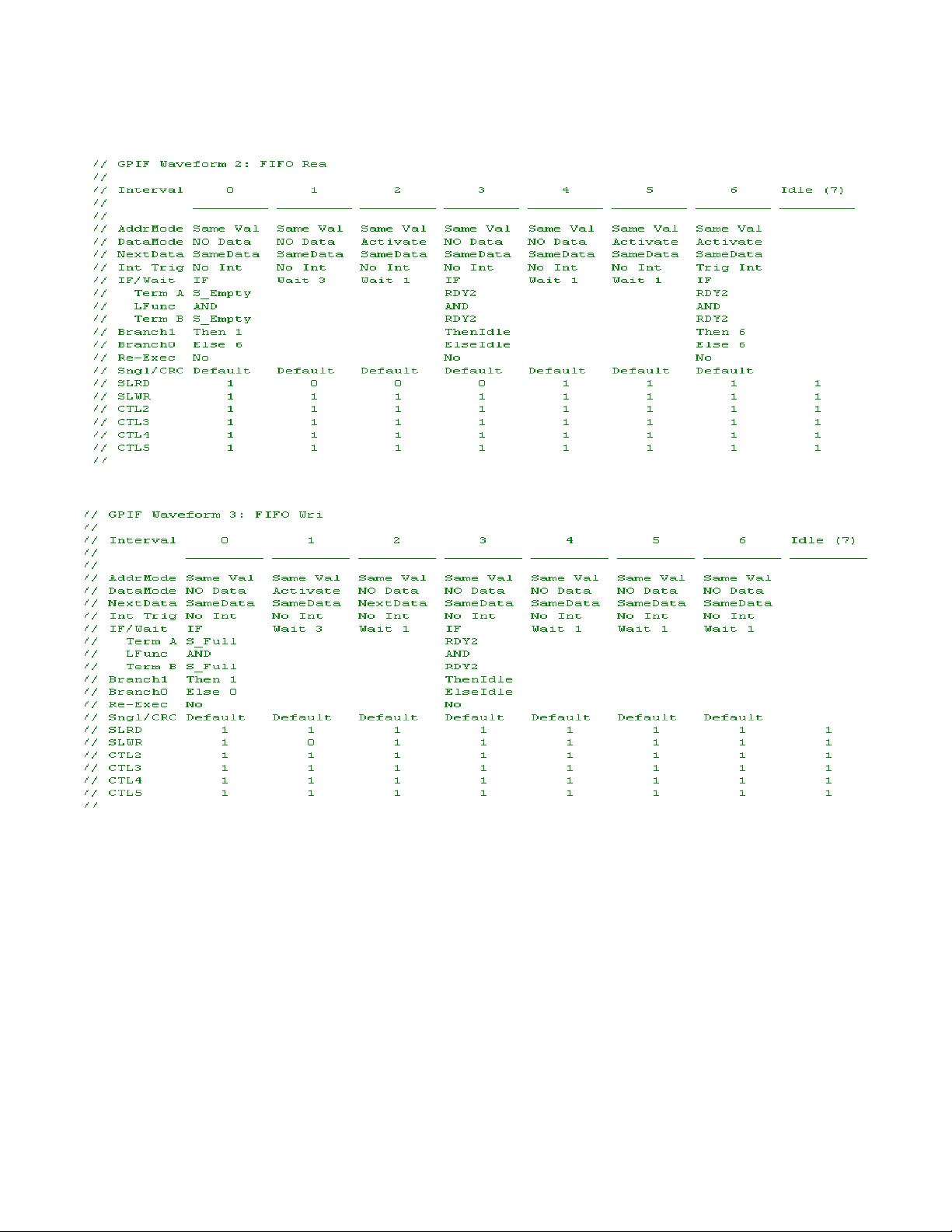
Figure 4. FIFO Read Waveform in gpif.c
Figure 5. FIFO Write Waveform in gpif.c
AN6077
8051 Firmware Programming (Master)
This section describes how to configure the 8051 to support
the interface on the master side (register settings and others)
and discusses the firmware implemented to perform data
transactions over the local bus and the USB. The complete
code listing is provided at the end of this document.
Firmware Architecture
The firmware is designed to handle USB INs and OUTs a rbitrarily (for example, the direction of transfer is not favored).
It is also fairly deterministic in its approach and is ‘eventdriven’ by the following key conditions:
OUTs (FIFO Writes)
■ Endpoint 2 OUT Has Data
■ Peripheral Interface Not Busy (GPIF IDLE)
■ Slave Interface FIFO Not Full
INs (FIFO Reads)
■ Peripheral Interface Not Busy (GPIF IDLE)
■ Slave Interface FIFO Not Empty
■ Endpoint 6IN Available Not Full
Since the GPIF is a shared resource between FIFO Reads
and Writes, the peripheral interface status is always checked
before committing the GPIF to launch any form of physi cal
bus transactions. The firmware is optimized for 512-byte
FIFO Reads and Writes with other mechanisms in place to
handle short packets (1–511 bytes).
February 19, 2008 Document No. 001-15342 Rev. ** 4
[+] Feedback
Page 5

AN6077
The firmware uses the AUTO mode for both IN and OUT
transfers. This means that the maximum size (512 bytes)
packets are committed automatically from the peripheral
domain to the USB domain for OUT transfers. For IN transfers, they are committed from USB to the peripheral domain.
The 8051 is not involved in committing packets. Short packets are handled by the master strobing the PKTEND of the
slave. In this implementation, the PKTEND of the slave is tied
to CTL2 of the master. So the GPIFIDLECTL register is written to strobe PKTEND.
Psuedocode for Master OUT
if GPIF is IDLE
if there is a packet in EP2 OUT
if the peripheral is not FULL
trigger the GPIF Write Transaction
// handle short packet
if the transaction count < 512
if GPIF is IDLE
strobe PKTEND
else
// do nothing; wait for GPIF to be done
else
// do nothing; packet is not short packet
else
// do nothing; peripheral is FULL
else
// do nothing; no data is available to transfer
else
// do nothing; GPIF is not IDLE
Psuedocode for Master IN
if the GPIF is IDLE
if the peripheral is not empty
if EP6 IN is not full
trigger the GPIF Read transaction
if packet is short packet
commit the packet by writing INPKTEND
else
//do nothing; packet is not short
else
//do nothing; EP6 IN is full
else
//do nothing; the peripheral does not have data to transfer
else
//do nothing; GPIF is busy
Expanded Master OUT Code
if( GPIFTRIG & 0x80 )
{
// DONE=1, when GPIF is "idle"
// check if there is a packet in the peripheral domain (EP2OUT)
if( EP24FIFOFLGS & 0x02 )
{
// EF=1 when buffer "empty", for example, no more data to transfer
}
else
{
// EF=0, when slave fifo is "not empty"
// the cpu passed the packet to the peripheral domain (AUTO OUT)
// check if peripheral "not full"
if( GPIFREADYSTAT & 0x02 )
{
// RDY1=1, when peripheral is "not" FULL (tied to peripheral "full" flag)
// drive FIFOADDR lines
OEA = 0xC0;
February 19, 2008 Document No. 001-15342 Rev. ** 5
[+] Feedback
Page 6

IOA = 0x80;
xFIFOTC_OUT = ( ( EP2FIFOBCH << 8 ) + EP2FIFOBCL );
// setup GPIF transaction count
SYNCDELAY;
EP2GPIFTCH = EP2FIFOBCH;
SYNCDELAY;
EP2GPIFTCL = EP2FIFOBCL;
// trigger FIFO write transaction(s)
SYNCDELAY;
GPIFTRIG = GPIFTRIGWR | GPIF_EP2;
// once master (GPIF) drains OUT packet, it (re)arms to usb domain
// this path is always auto, meaning core handles it
if( xFIFOTC_OUT < enum_pkt_size )
{
// handle short packet to peripheral
// wait for the transaction to terminate naturally
while( !( GPIFTRIG & 0x80 ) )
{
; // poll GPIFTRIG.7, DONE bit
}
// signal short packet to peripheral here
// in this implementation CTL2 is tied to PKTEND of slave strobe PKTEND of slave
AN6077
GPIFIDLECTL |= 0x04;
GPIFIDLECTL &= 0xFB;
GPIFIDLECTL |= 0x04;
}
else
{
// was max packet size
// let transaction terminate naturally
}
}
else
{
// RDY1=0, when peripheral is FULL
}
}
}
else
{
// DONE=0 when GPIF is "not" IDLE
}
Expanded Master IN Code
// is the GPIF idle
if( GPIFTRIG & 0x80 )
{
// check if peripheral is "not empty"
if( GPIFREADYSTAT & 0x01 )
{
// RDY0=1, when peripheral is "not empty"
// drive FIFOADDR lines
OEA = 0xC0;
IOA = 0x00;
February 19, 2008 Document No. 001-15342 Rev. ** 6
[+] Feedback
Page 7

if( EP68FIFOFLGS & 0x01 )
{
// EP6FF=1, when fifo "full"
}
else
{
// EP6FF=0, when fifo "not full", for example, buffer available
// setup GPIF transaction count
SYNCDELAY;
EP6GPIFTCH = 0x02;
SYNCDELAY;
EP6GPIFTCL = 0x00;
// trigger FIFO read transaction(s), using SFR
SYNCDELAY;
GPIFTRIG = GPIFTRIGRD | GPIF_EP6;
// wait for transaction to terminate naturally
SYNCDELAY;
while( !( GPIFTRIG & 0x80 ) )
{
; // poll GPIFTRIG.7, DONE bit
}
// AUTOOUT=1, core handles transfers
// cpu is not in the data path however, cpu is responsible for committing "short packets"
AN6077
if( xFIFOTC_IN < enum_pkt_size )
xFIFOTC_IN = ( ( EP6FIFOBCH << 8 ) + EP6FIFOBCL );
{
// handle short packet from peripheral
SYNCDELAY;
INPKTEND = 0x06;
// w/skip=0;commit however many bytes in packet.
SYNCDELAY;
}
else
{
// core commits packet via EPxAUTOINLENH/L
}
else
{
// master has all the data the peripheral sent
}
}
else
{
// peripheral interface busy
}
}
Firmware for the Slave
Since the slave works only in AUTO mode, there is no code
required for data transfer to and from the master, except for
the initialization of registers and specifying the
EP6AUTOINLEN registers.
Summary
This application note describes how to set up the GPIF to
transfer data over an 8-bit asynchronous interface (to the
slave FIFO of another EZ-USB FX2LP). It includes hardware
setup, creating GPIF waveforms, and writing the 8051 code
that arbitrarily handles both USB INs and OUTs.
This application note is centered around a specific back-toback board setup with two EZ-USB FX2LP boards. However,
many concepts and insights conveyed in this document can
be applied to and used as a basic framework for mainstream
applications.
February 19, 2008 Document No. 001-15342 Rev. ** 7
[+] Feedback
Page 8

Code Listing for Master Side
#pragma NOIV // Do not generate interrupt vectors
#include "fx2.h"
#include "fx2regs.h"
#include "fx2sdly.h" // SYNCDELAY macro
extern BOOL GotSUD; // Received setup data flag
extern BOOL Sleep;
extern BOOL Rwuen;
extern BOOL Selfpwr;
BYTE Configuration; // Current configuration
BYTE AlternateSetting; // Alternate settings
// proto's from "gpif.c"
void GpifInit( void );
// 512 for high speed, 64 for full speed
static WORD enum_pkt_size = 0x0000;
// when set firmware running in TD_Poll( ); handles data transfers
BOOL td_poll_handles_transfers = 1;
AN6077
// when set cpu is out of the data path
BOOL endp_auto_mode_enabled = 1;
//----------------------------------------------------------------------------// Task Dispatcher hooks
// The following hooks are called by the task dispatcher.
//----------------------------------------------------------------------------void TD_Init( void )
{ // Called once at startup
CPUCS = 0x10; // CLKSPD[1:0]=10, for 48 MHz operation
// CLKOE=0, don't drive CLKOUT
GpifInit( ); // init GPIF engine via GPIFTool output file
// Registers which require a synchronization delay, see section 15.14
// FIFORESET FIFOPINPOLAR
// INPKTEND OUTPKTEND
// EPxBCH:L REVCTL
// GPIFTCB3 GPIFTCB2
// GPIFTCB1 GPIFTCB0
// EPxFIFOPFH:L EPxAUTOINLENH:L
// EPxFIFOCFG EPxGPIFFLGSEL
// PINFLAGSxx EPxFIFOIRQ
// EPxFIFOIE GPIFIRQ
// GPIFIE GPIFADRH:L
// UDMACRCH:L EPxGPIFTRIG
// GPIFTRIG
SYNCDELAY; // see TRM section 15.14
REVCTL = 0x02; // REVCTL.1=1;
SYNCDELAY;
EP2CFG = 0xA0; // BUF[1:0]=00 for 4x buffering
// EP6 512 BULK IN 4x
SYNCDELAY;
EP6CFG = 0xE0; // BUF[1:0]=00 for 4x buffering
February 19, 2008 Document No. 001-15342 Rev. ** 8
[+] Feedback
Page 9

// EP4 and EP8 are not used in this implementation
SYNCDELAY; //
EP4CFG = 0x20; // clear valid bit
SYNCDELAY; //
EP8CFG = 0x60; // clear valid bit
SYNCDELAY; //
FIFORESET = 0x80; // activate NAK-ALL to avoid race conditions
SYNCDELAY; //
FIFORESET = 0x82; // reset, FIFO 2
SYNCDELAY; //
FIFORESET = 0x84; // reset, FIFO 4
SYNCDELAY; //
FIFORESET = 0x86; // reset, FIFO 6
SYNCDELAY; //
FIFORESET = 0x88; // reset, FIFO 8
SYNCDELAY; //
FIFORESET = 0x00; // deactivate NAK-ALL
// 8-bit bus (WORDWIDE=0)
SYNCDELAY;
EP2FIFOCFG = 0x00;
SYNCDELAY;
EP6FIFOCFG = 0x0C;
SYNCDELAY;
EP2BCL = 0x00; // arm first buffer
SYNCDELAY; //
EP2BCL = 0x00; // arm second buffer
SYNCDELAY; //
EP2BCL = 0x00; // arm third buffer
SYNCDELAY; //
EP2BCL = 0x00; // arm fourth buffer
SYNCDELAY;
SYNCDELAY;
OUTPKTEND = 0x02;
SYNCDELAY;
OUTPKTEND = 0x02;
SYNCDELAY;
OUTPKTEND = 0x02;
SYNCDELAY;
OUTPKTEND = 0x02;
SYNCDELAY;
AN6077
SYNCDELAY; //
EP2FIFOCFG = 0x10;
SYNCDELAY;
// IN endp's come up in the cpu/peripheral domain
// setup INT4 as internal source for GPIF interrupts
// using INT4CLR (SFR), automatically enabled
INTSETUP |= 0x03; // Enable INT4 FIFO/GPIF Autovectoring
SYNCDELAY; // used here as "delay"
EXIF &= ~0x40; // just in case one was pending.
SYNCDELAY; // used here as "delay"
GPIFIRQ = 0x02;
SYNCDELAY; //
GPIFIE = 0x02; // Enable GPIFWF interrupt
SYNCDELAY; //
EIE |= 0x04; // Enable INT4 ISR, EIE.2(EIEX4=1)
February 19, 2008 Document No. 001-15342 Rev. ** 9
[+] Feedback
Page 10

}
#define GPIFTRIGWR 0
#define GPIFTRIGRD 4
#define GPIF_EP2 0
#define GPIF_EP4 1
#define GPIF_EP6 2
#define GPIF_EP8 3
void TD_Poll( void )
{ // Called repeatedly while the device is idle
static WORD xFIFOTC_OUT = 0x0000;
static WORD xFIFOTC_IN = 0x0000;
// Registers which require a synchronization delay, see section 15.14
// FIFORESET FIFOPINPOLAR
// INPKTEND OUTPKTEND
// EPxBCH:L REVCTL
// GPIFTCB3 GPIFTCB2
// GPIFTCB1 GPIFTCB0
// EPxFIFOPFH:L EPxAUTOINLENH:L
// EPxFIFOCFG EPxGPIFFLGSEL
// PINFLAGSxx EPxFIFOIRQ
// EPxFIFOIE GPIFIRQ
// GPIFIE GPIFADRH:L
// UDMACRCH:L EPxGPIFTRIG
// GPIFTRIG
OEA = 0xC0;
IOA = 0x80;
AN6077
if( td_poll_handles_transfers )
{
// Handle OUT data
// is the peripheral interface idle
if( GPIFTRIG & 0x80 )
{
// DONE=1, when GPIF is "idle"
// check if there is a packet in the peripheral domain (EP2OUT)
if( EP24FIFOFLGS & 0x02 )
{
// EF=1 when buffer "empty", for example, no more data to transfer
}
else
{
// EF=0, when slave fifo is "not empty"
// the cpu passed the packet to the peripheral domain (AUTO OUT)
// check if peripheral "not full"
if( GPIFREADYSTAT & 0x02 )
{
// RDY1=1, when peripheral is "not" FULL (tied to peripheral "full" flag)
// drive FIFOADDR lines
OEA = 0xC0;
IOA = 0x80;
xFIFOTC_OUT = ( ( EP2FIFOBCH << 8 ) + EP2FIFOBCL );
February 19, 2008 Document No. 001-15342 Rev. ** 10
[+] Feedback
Page 11

// setup GPIF transaction count
SYNCDELAY;
EP2GPIFTCH = EP2FIFOBCH;
SYNCDELAY;
EP2GPIFTCL = EP2FIFOBCL;
// trigger FIFO write transaction(s), using SFR
SYNCDELAY;
GPIFTRIG = GPIFTRIGWR | GPIF_EP2;
// once master (GPIF) drains OUT packet, it (re)arms to usb domain
// this path is always auto, meaning core handles it
if( xFIFOTC_OUT < enum_pkt_size )
{
// handle short packet to peripheral
// wait for the transaction to terminate naturally
while( !( GPIFTRIG & 0x80 ) )
{
; // poll GPIFTRIG.7, DONE bit...
}
// signal short packet to peripheral here
// in this implementation CTL2 is tied to PKTEND of slave
// strobe PKTEND of slave
AN6077
GPIFIDLECTL |= 0x04;
GPIFIDLECTL &= 0xFB;
GPIFIDLECTL |= 0x04;
}
else
{
// was max packet size
// let transaction terminate naturally
}
}
else
{
// RDY1=0, when peripheral is FULL
}
}
}
else
{
// DONE=0 when GPIF is "not" IDLE
}
// Handle IN data
// is the GPIF idle
if( GPIFTRIG & 0x80 )
{
// check if peripheral is "not empty"
if( GPIFREADYSTAT & 0x01 )
{
February 19, 2008 Document No. 001-15342 Rev. ** 1 1
[+] Feedback
Page 12

AN6077
// RDY0=1, when peripheral is "not empty"
// drive FIFOADDR lines
OEA = 0xC0;
IOA = 0x00;
if( EP68FIFOFLGS & 0x01 )
{
// EP6FF=1, when fifo "full"
}
else
{
// EP6FF=0, when fifo "not full", for example, buffer available
// setup GPIF transaction count
SYNCDELAY;
EP6GPIFTCH = 0x02;
SYNCDELAY;
EP6GPIFTCL = 0x00;
// trigger FIFO read transaction(s), using SFR
SYNCDELAY;
GPIFTRIG = GPIFTRIGRD | GPIF_EP6;
// wait for the transaction to terminate naturally
SYNCDELAY;
while( !( GPIFTRIG & 0x80 ) )
{
; // poll GPIFTRIG.7, DONE bit
}
// AUTOOUT=1, core handles transfers
// cpu is not in the data path
// however, cpu is responsible for committing "short packets"
xFIFOTC_IN = ( ( EP6FIFOBCH << 8 ) + EP6FIFOBCL );
if( xFIFOTC_IN < enum_pkt_size )
{
// handle short packet from peripheral
SYNCDELAY;
INPKTEND = 0x06; // w/skip=0;commit however many bytes in packet.
SYNCDELAY;
}
else
{
// core commits packet via EPxAUTOINLENH/L registers
}
}
}
else
{
// master has all the data the peripheral sent
}
}
else
{
// peripheral interface busy
}
}
February 19, 2008 Document No. 001-15342 Rev. ** 12
[+] Feedback
Page 13

}
BOOL TD_Suspend( void )
{ // Called before the device goes into suspend mode
return( TRUE );
}
BOOL TD_Resume( void )
{ // Called after the device resumes
return( TRUE );
}
//----------------------------------------------------------------------------// Device Request hooks
// The following hooks are called by the end point 0 device request parser.
//----------------------------------------------------------------------------BOOL DR_GetDescriptor( void )
{
return( TRUE );
}
BOOL DR_SetConfiguration( void )
{ // Called when a Set Configuration command is received
if( EZUSB_HIGHSPEED( ) )
{ // FX2LP in high speed mode
SYNCDELAY; //
EP6AUTOINLENH = 0x02; // set core AUTO commit len = 512 bytes
SYNCDELAY; //
EP6AUTOINLENL = 0x00;
SYNCDELAY; //
enum_pkt_size = 512; // max. pkt. size = 512 bytes
}
else
{ // FX2LP in full speed mode
SYNCDELAY; //
EP6AUTOINLENH = 0x00; // set core AUTO commit len = 64 bytes
SYNCDELAY; //
EP6AUTOINLENL = 0x40;
SYNCDELAY; //
enum_pkt_size = 64; // max. pkt. size = 64 bytes
}
Configuration = SETUPDAT[ 2 ];
return( TRUE ); // Handled by user code
}
AN6077
BOOL DR_GetConfiguration( void )
{ // Called when a Get Configuration command is received
EP0BUF[ 0 ] = Configuration;
EP0BCH = 0;
EP0BCL = 1;
return(TRUE); // Handled by user code
}
BOOL DR_SetInterface( void )
{ // Called when a Set Interface command is received
AlternateSetting = SETUPDAT[ 2 ];
return( TRUE ); // Handled by user code
}
BOOL DR_GetInterface( void )
February 19, 2008 Document No. 001-15342 Rev. ** 13
[+] Feedback
Page 14

{ // Called when a Set Interface command is received
EP0BUF[ 0 ] = AlternateSetting;
EP0BCH = 0;
EP0BCL = 1;
return( TRUE ); // Handled by user code
}
BOOL DR_GetStatus( void )
{
return( TRUE );
}
BOOL DR_ClearFeature( void )
{
return( TRUE );
}
BOOL DR_SetFeature( void )
{
return( TRUE );
}
AN6077
//----------------------------------------------------------------------------// USB Interrupt Handlers
// The following functions are called by the USB interrupt jump table.
//-----------------------------------------------------------------------------
// Setup Data Available Interrupt Handler
void ISR_Sudav( void ) interrupt 0
{
GotSUD = TRUE; // Set flag
EZUSB_IRQ_CLEAR( );
USBIRQ = bmSUDAV; // Clear SUDAV IRQ
}
// Setup Token Interrupt Handler
void ISR_Sutok( void ) interrupt 0
{
EZUSB_IRQ_CLEAR( );
USBIRQ = bmSUTOK; // Clear SUTOK IRQ
}
void ISR_Sof( void ) interrupt 0
{
EZUSB_IRQ_CLEAR( );
USBIRQ = bmSOF; // Clear SOF IRQ
}
void ISR_Ures( void ) interrupt 0
{
if ( EZUSB_HIGHSPEED( ) )
{
pConfigDscr = pHighSpeedConfigDscr;
pOtherConfigDscr = pFullSpeedConfigDscr;
}
else
{
pConfigDscr = pFullSpeedConfigDscr;
pOtherConfigDscr = pHighSpeedConfigDscr;
}
February 19, 2008 Document No. 001-15342 Rev. ** 14
[+] Feedback
Page 15

EZUSB_IRQ_CLEAR( );
USBIRQ = bmURES; // Clear URES IRQ
}
void ISR_Susp( void ) interrupt 0
{
Sleep = TRUE;
EZUSB_IRQ_CLEAR( );
USBIRQ = bmSUSP;
}
void ISR_Highspeed( void ) interrupt 0
{
if ( EZUSB_HIGHSPEED( ) )
{
pConfigDscr = pHighSpeedConfigDscr;
pOtherConfigDscr = pFullSpeedConfigDscr;
}
else
{
pConfigDscr = pFullSpeedConfigDscr;
pOtherConfigDscr = pHighSpeedConfigDscr;
}
AN6077
EZUSB_IRQ_CLEAR( );
USBIRQ = bmHSGRANT;
}
void ISR_Ep0ack( void ) interrupt 0
{
}
void ISR_Stub( void ) interrupt 0
{
}
void ISR_Ep0in( void ) interrupt 0
{
}
void ISR_Ep0out( void ) interrupt 0
{
}
void ISR_Ep1in( void ) interrupt 0
{
}
void ISR_Ep1out( void ) interrupt 0
{
}
void ISR_Ep2inout( void ) interrupt 0
{
}
void ISR_Ep4inout( void ) interrupt 0
{
}
void ISR_Ep6inout( void ) interrupt 0
{
}
void ISR_Ep8inout( void ) interrupt 0
{
}
void ISR_Ibn( void ) interrupt 0
{
}
void ISR_Ep0pingnak( void ) interrupt 0
{
February 19, 2008 Document No. 001-15342 Rev. ** 15
[+] Feedback
Page 16

}
void ISR_Ep1pingnak( void ) interrupt 0
{
}
void ISR_Ep2pingnak( void ) interrupt 0
{
}
void ISR_Ep4pingnak( void ) interrupt 0
{
}
void ISR_Ep6pingnak( void ) interrupt 0
{
}
void ISR_Ep8pingnak( void ) interrupt 0
{
}
void ISR_Errorlimit( void ) interrupt 0
{
}
void ISR_Ep2piderror( void ) interrupt 0
{
}
void ISR_Ep4piderror( void ) interrupt 0
{
}
void ISR_Ep6piderror( void ) interrupt 0
{
}
void ISR_Ep8piderror( void ) interrupt 0
{
}
void ISR_Ep2pflag( void ) interrupt 0
{
}
void ISR_Ep4pflag( void ) interrupt 0
{
}
void ISR_Ep6pflag( void ) interrupt 0
{
}
void ISR_Ep8pflag( void ) interrupt 0
{
}
void ISR_Ep2eflag( void ) interrupt 0
{
}
void ISR_Ep4eflag( void ) interrupt 0
{
}
void ISR_Ep6eflag( void ) interrupt 0
{
}
void ISR_Ep8eflag( void ) interrupt 0
{
}
void ISR_Ep2fflag( void ) interrupt 0
{
}
void ISR_Ep4fflag( void ) interrupt 0
{
}
void ISR_Ep6fflag( void ) interrupt 0
{
AN6077
February 19, 2008 Document No. 001-15342 Rev. ** 16
[+] Feedback
Page 17

}
void ISR_Ep8fflag( void ) interrupt 0
{
}
void ISR_GpifComplete( void ) interrupt 0
{
}
void ISR_GpifWaveform( void ) interrupt 0
{ // FIFORd WF detected peripheral prematurely empty (less than max. pkt. size)
GPIFABORT = 0xFF; // abort to handle shortpkt
INPKTEND = 0x06;
SYNCDELAY;
EXIF &= ~0x40;
INT4CLR = 0xFF; // automatically enabled at POR
SYNCDELAY;
}
Code Listing for the Slave Side
#pragma NOIV // Do not generate interrupt vectors
#include "fx2.h"
#include "fx2regs.h"
#include "fx2sdly.h" // SYNCDELAY macro
AN6077
extern BOOL GotSUD; // Received setup data flag
extern BOOL Sleep;
extern BOOL Rwuen;
extern BOOL Selfpwr;
BYTE Configuration; // Current configuration
BYTE AlternateSetting; // Alternate settings
//----------------------------------------------------------------------------// Task Dispatcher hooks
// The following hooks are called by the task dispatcher.
//----------------------------------------------------------------------------void TD_Init( void )
{ // Called once at startup
CPUCS = 0x10; // CLKSPD[1:0]=10, for 48 MHz operation
SYNCDELAY;
REVCTL=0x02;
IFCONFIG = 0xCB;
// IFCLKSRC=1 , FIFOs executes on internal clk source
// x MHz=1 , 48 MHz internal clk rate
// IFCLKOE=0 , Don't drive IFCLK pin signal at 48 MHz
// IFCLKPOL=0 , Don't invert IFCLK pin signal from internal clk
// ASYNC=1 , master samples asynchronous
// GSTATE=0 , Don't drive GPIF states out on PORTE[2:0], debug WF
// IFCFG[1:0]=11, FX2 in slave FIFO mode
// Registers which require a synchronization delay, see section 15.14
// FIFORESET FIFOPINPOLAR
// INPKTEND OUTPKTEND
// EPxBCH:L REVCTL
// GPIFTCB3 GPIFTCB2
// GPIFTCB1 GPIFTCB0
// EPxFIFOPFH:L EPxAUTOINLENH:L
// EPxFIFOCFG EPxGPIFFLGSEL
February 19, 2008 Document No. 001-15342 Rev. ** 17
[+] Feedback
Page 18

// PINFLAGSxx EPxFIFOIRQ
// EPxFIFOIE GPIFIRQ
// GPIFIE GPIFADRH:L
// UDMACRCH:L EPxGPIFTRIG
// GPIFTRIG
SYNCDELAY;
FIFORESET = 0x80; // activate NAK-ALL to avoid race conditions
SYNCDELAY; // see TRM section 15.14
FIFORESET = 0x82; // reset, FIFO 2
SYNCDELAY; //
FIFORESET = 0x84; // reset, FIFO 4
SYNCDELAY; //
FIFORESET = 0x86; // reset, FIFO 6
SYNCDELAY; //
FIFORESET = 0x88; // reset, FIFO 8
SYNCDELAY; //
FIFORESET = 0x00; // deactivate NAK-ALL
SYNCDELAY;
PINFLAGSAB = 0xEF; // FLAGA - fixed EP8FF, FLAGB - fixed EP6FF
SYNCDELAY;
PINFLAGSCD = 0x98; // FLAGC - fixed EP2EF, FLAGD - fixed EP4EF
SYNCDELAY;
PORTACFG |= 0x80; // FLAGD, set alt. func. of PA7 pin
SYNCDELAY;
FIFOPINPOLAR = 0x00; // all signals active low
SYNCDELAY;
EP2CFG = 0xA0;
SYNCDELAY;
EP6CFG = 0xE0;
AN6077
// EP4 and EP8 are not used in this implementation
SYNCDELAY; //
EP4CFG = 0x20; // clear valid bit
SYNCDELAY; //
EP8CFG = 0x60; // clear valid bit
// handle the case where we were already in AUTO mode
EP2FIFOCFG = 0x00; // AUTOOUT=0, WORDWIDE=0
SYNCDELAY;
SYNCDELAY; //
EP2BCL = 0x00; // arm first buffer
SYNCDELAY; //
EP2BCL = 0x00; // arm second buffer
SYNCDELAY; //
EP2BCL = 0x00; // arm third buffer
SYNCDELAY; //
EP2BCL = 0x00; // arm fourth buffer
SYNCDELAY; //
SYNCDELAY;
OUTPKTEND = 0x02;
SYNCDELAY;
OUTPKTEND = 0x02;
SYNCDELAY;
OUTPKTEND = 0x02;
SYNCDELAY;
OUTPKTEND = 0x02;
SYNCDELAY;
February 19, 2008 Document No. 001-15342 Rev. ** 18
[+] Feedback
Page 19

EP2FIFOCFG = 0x10; // AUTOOUT=1, WORDWIDE=0
SYNCDELAY;
EP6FIFOCFG = 0x0C; // AUTOIN=1, ZEROLENIN=1, WORDWIDE=0
SYNCDELAY;
}
void TD_Poll( void )
{ // Called repeatedly while the device is idle
// nothing to do;slave fifo's are in AUTO mode
}
BOOL TD_Suspend( void )
{ // Called before the device goes into suspend mode
return( TRUE );
}
BOOL TD_Resume( void )
{ // Called after the device resumes
return( TRUE );
}
AN6077
//----------------------------------------------------------------------------// Device Request hooks
// The following hooks are called by the end point 0 device request parser.
//----------------------------------------------------------------------------BOOL DR_GetDescriptor( void )
{
return( TRUE );
}
BOOL DR_SetConfiguration( void )
{ // Called when a Set Configuration command is received
if( EZUSB_HIGHSPEED( ) )
{ // FX2LP in high speed mode
EP6AUTOINLENH = 0x02;
SYNCDELAY;
// set core AUTO commit len = 512 bytes
SYNCDELAY;
EP6AUTOINLENL = 0x00;
SYNCDELAY;
}
else
{ // FX2LP in full speed mode
EP6AUTOINLENH = 0x00;
SYNCDELAY;
// set core AUTO commit len = 64 bytes
SYNCDELAY;
EP6AUTOINLENL = 0x40;
SYNCDELAY;
}
Configuration = SETUPDAT[ 2 ];
return( TRUE ); // Handled by user code
}
BOOL DR_GetConfiguration( void )
{ // Called when a Get Configuration command is received
February 19, 2008 Document No. 001-15342 Rev. ** 19
[+] Feedback
Page 20

EP0BUF[ 0 ] = Configuration;
EP0BCH = 0;
EP0BCL = 1;
return(TRUE); // Handled by user code
}
BOOL DR_SetInterface( void )
{ // Called when a Set Interface command is received
AlternateSetting = SETUPDAT[ 2 ];
return( TRUE ); // Handled by user code
}
BOOL DR_GetInterface( void )
{ // Called when a Set Interface command is received
EP0BUF[ 0 ] = AlternateSetting;
EP0BCH = 0;
EP0BCL = 1;
return( TRUE ); // Handled by user code
}
BOOL DR_GetStatus( void )
{
return( TRUE );
}
AN6077
BOOL DR_ClearFeature( void )
{
return( TRUE );
}
BOOL DR_SetFeature( void )
{
return( TRUE );
}
BOOL DR_VendorCmnd( void )
{
return( TRUE );
}
//----------------------------------------------------------------------------// USB Interrupt Handlers
// The following functions are called by the USB interrupt jump table.
//-----------------------------------------------------------------------------
// Setup Data Available Interrupt Handler
void ISR_Sudav( void ) interrupt 0
{
GotSUD = TRUE; // Set flag
EZUSB_IRQ_CLEAR( );
USBIRQ = bmSUDAV; // Clear SUDAV IRQ
}
// Setup Token Interrupt Handler
void ISR_Sutok( void ) interrupt 0
{
EZUSB_IRQ_CLEAR( );
USBIRQ = bmSUTOK; // Clear SUTOK IRQ
}
void ISR_Sof( void ) interrupt 0
{
EZUSB_IRQ_CLEAR( );
February 19, 2008 Document No. 001-15342 Rev. ** 20
[+] Feedback
Page 21

USBIRQ = bmSOF; // Clear SOF IRQ
}
void ISR_Ures( void ) interrupt 0
{
if ( EZUSB_HIGHSPEED( ) )
{
pConfigDscr = pHighSpeedConfigDscr;
pOtherConfigDscr = pFullSpeedConfigDscr;
}
else
{
pConfigDscr = pFullSpeedConfigDscr;
pOtherConfigDscr = pHighSpeedConfigDscr;
}
EZUSB_IRQ_CLEAR( );
USBIRQ = bmURES; // Clear URES IRQ
}
void ISR_Susp( void ) interrupt 0
{
Sleep = TRUE;
EZUSB_IRQ_CLEAR( );
USBIRQ = bmSUSP;
}
AN6077
void ISR_Highspeed( void ) interrupt 0
{
if ( EZUSB_HIGHSPEED( ) )
{
pConfigDscr = pHighSpeedConfigDscr;
pOtherConfigDscr = pFullSpeedConfigDscr;
}
else
{
pConfigDscr = pFullSpeedConfigDscr;
pOtherConfigDscr = pHighSpeedConfigDscr;
}
EZUSB_IRQ_CLEAR( );
USBIRQ = bmHSGRANT;
}
void ISR_Ep0ack( void ) interrupt 0
{
}
void ISR_Stub( void ) interrupt 0
{
}
void ISR_Ep0in( void ) interrupt 0
{
}
void ISR_Ep0out( void ) interrupt 0
{
}
void ISR_Ep1in( void ) interrupt 0
{
}
void ISR_Ep1out( void ) interrupt 0
{
}
void ISR_Ep2inout( void ) interrupt 0
{
February 19, 2008 Document No. 001-15342 Rev. ** 21
[+] Feedback
Page 22

}
void ISR_Ep4inout( void ) interrupt 0
{
}
void ISR_Ep6inout( void ) interrupt 0
{
}
void ISR_Ep8inout( void ) interrupt 0
{
}
void ISR_Ibn( void ) interrupt 0
{
}
void ISR_Ep0pingnak( void ) interrupt 0
{
}
void ISR_Ep1pingnak( void ) interrupt 0
{
}
void ISR_Ep2pingnak( void ) interrupt 0
{
}
void ISR_Ep4pingnak( void ) interrupt 0
{
}
void ISR_Ep6pingnak( void ) interrupt 0
{
}
void ISR_Ep8pingnak( void ) interrupt 0
{
}
void ISR_Errorlimit( void ) interrupt 0
{
}
void ISR_Ep2piderror( void ) interrupt 0
{
}
void ISR_Ep4piderror( void ) interrupt 0
{
}
void ISR_Ep6piderror( void ) interrupt 0
{
}
void ISR_Ep8piderror( void ) interrupt 0
{
}
void ISR_Ep2pflag( void ) interrupt 0
{
}
void ISR_Ep4pflag( void ) interrupt 0
{
}
void ISR_Ep6pflag( void ) interrupt 0
{
}
void ISR_Ep8pflag( void ) interrupt 0
{
}
void ISR_Ep2eflag( void ) interrupt 0
{
}
void ISR_Ep4eflag( void ) interrupt 0
{
AN6077
February 19, 2008 Document No. 001-15342 Rev. ** 22
[+] Feedback
Page 23

AN6077
}
void ISR_Ep6eflag( void ) interrupt 0
{
}
void ISR_Ep8eflag( void ) interrupt 0
{
}
void ISR_Ep2fflag( void ) interrupt 0
{
}
void ISR_Ep4fflag( void ) interrupt 0
{
}
void ISR_Ep6fflag( void ) interrupt 0
{
}
void ISR_Ep8fflag( void ) interrupt 0
{
}
void ISR_GpifComplete( void ) interrupt 0
{
}
void ISR_GpifWaveform( void ) interrupt 0
{
}
EZ-USB FX2LP is a trademark of Cypress Semiconductor Corp. All products and company names mentioned in this document are the trademarks of
their respective holders.
Cypress Semiconductor
198 Champion Court
San Jose, CA 95134-1709
Phone: 408-943-2600
Fax: 408-943-4730
http://www.cypress.com
© Cypress Semiconductor Corpo ration, 2006-2008. The information containe d herein is subject to change without notice. Cypress Semiconductor
Corporation assumes no responsibility for the use of any circuitry other than circuitry embodied in a Cypress product. Nor does it convey or imply any
license under patent or other rights. Cypr ess prod ucts are not wa rranted no r inten ded to be u sed for medical, l ife suppor t, lif e saving, cri tical control or
safety applications, unless pursuant to an ex press written agre ement with Cypres s. Furthermore, Cy press does not au thorize its products for use as critical
components in life-support systems where a malfunction or failure may reasonably be expected to result in significant injury to the user. The inclusion of
Cypress products in life-support sy stems application implies that the manufacturer assumes all r isk of such use and in doing so indemnifies Cypress
against all charges.
This Source Code (software and/or firmware ) is own ed by Cypr ess Semi conductor Corporat ion (Cy press) an d is prot ected by and sub ject to worldwide
patent protection (United St ates and foreign), United St ates copyright laws and international treaty provisions. Cypress hereby grants to licensee a personal,
non-exclusive, non-transferable license to copy, use, modify, create derivative works of, and compile the Cypress Source Code and derivative works for
the sole purpose of creating custom software and or firmware in support of licensee product to be used only in conjunction with a Cypress integrated circuit
as specified in the applicable agreement. Any reproduction, modification, translation, compilation, or representation of this Source Code except as specified
above is prohibited without the express written permission of Cypress.
Disclaimer: CYPRESS MAKES NO WARRANTY OF ANY KIND, EXPRESS OR IMPLIED, WITH REGARD TO THIS MA TERIAL, INCLUDING, BUT NOT
LIMITED TO, THE IMPLIED WARRANTIES OF MERCHANTABILITY AND FITNESS FOR A PARTICULAR PURPOSE. Cy press reserves the right t o
make changes without further notice to the materials described herein. Cypress does not assume any liability arising out of the application or use of any
product or circuit described herein. Cypress does not authorize its products for use as critical components in life-support systems where a malfunction or
failure may reasonably be expected to result in significant injury to the user. The inclusion of Cypress' product in a life-support systems application implies
that the manufacturer assumes all risk of such use and in doing so indemnifies Cypress against all charges.
Use may be limited by and subject to the applicable Cypress software license agreement.
February 19, 2008 Document No. 001-15342 Rev. ** 23
[+] Feedback
 Loading...