


©2008 Cypress Computer Systems,Inc. • www.cypressworld.com 3/4/08 Page 1
MAN-FA-DPX-5500 v1.00
DPX-5500 Series
Wireless Reader Extenders
Operations Manual
Model DPX-5510 Shown
©2008 Cypress Computer Systems,Inc. • www.cypressworld.com 3/4/08 Page 2
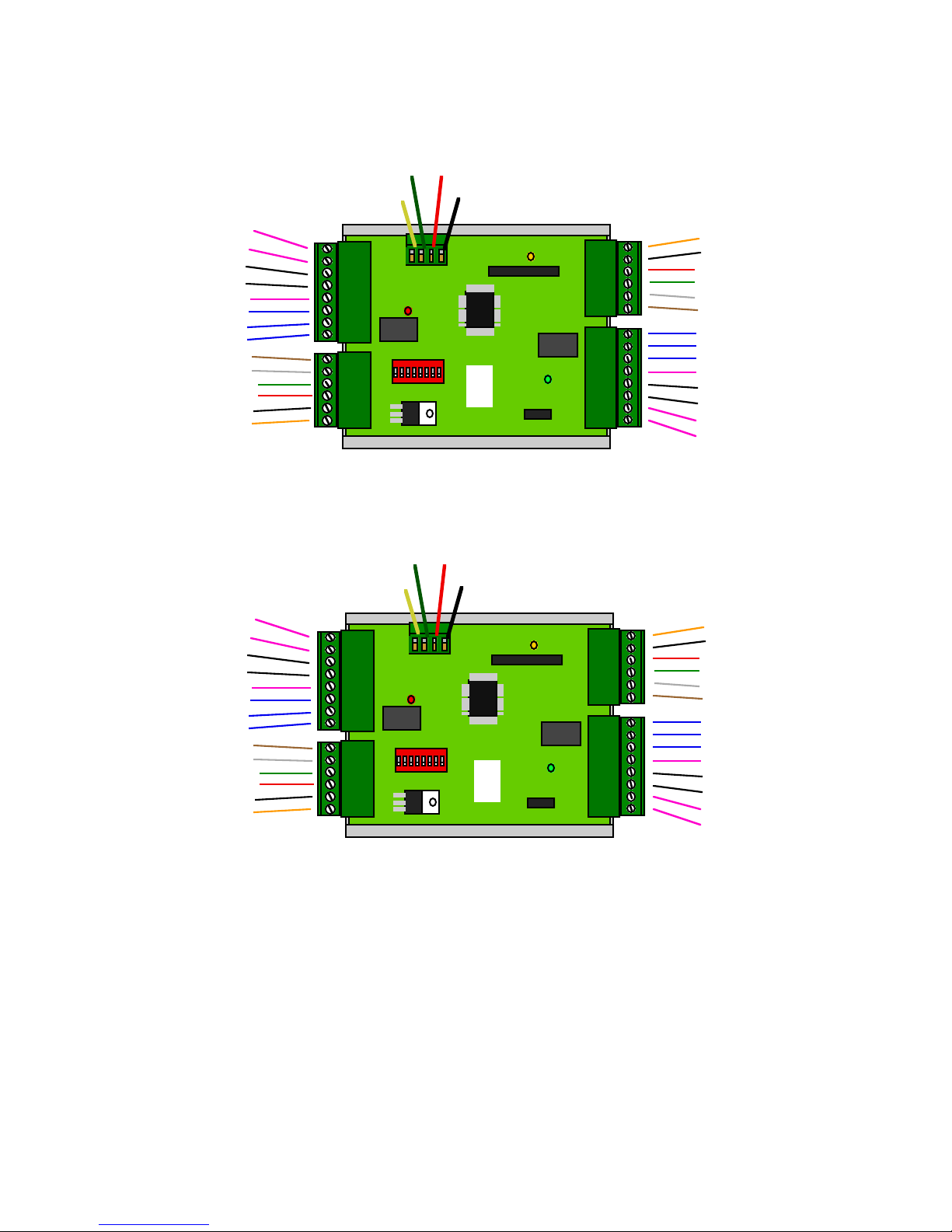
Connector Terminal Identification- Quick Reference
Panel /Port # 1 Signals
+8 - 24 VDC
Ground
+5 VDC
Data 0 /Clock
Data 1 /Data
LED
Alarm Relay N.C.
Alarm Relay Com
Alarm Relay N.O.
Alarm Programming Resistor
Aux #3 Programming Resistor
Aux Digital I/O #1 Input
Aux Digital I/O #2 Output
Aux Digital I/O #3 Output
N/C
Strike Relay N.C.
Strike Relay Com
Strike Relay N.O.
Alarm Digital Input
Aux Digital I/O #3 Input
Aux Digital I/O #1 Output
Reader # 2 Signals
Reader # 1 Signals
N/C
Alarm Digital Input
Aux Digital I/O #3 Input
Aux Digital I/O #1 Output
Aux Digital I/O #2 Input
Aux Digital I/O #2 Input
Strike Relay N.O
Strike Relay Com
Strike Relay N.C.
R
C
+8 - 24 VDC
Ground
+5 VDC
Data 0 /Clock
Data 1 /Data
LED
Alarm Relay N.C
Alarm Relay Com
Alarm Relay N.O
Alarm Programming Resistor
Aux #3 Programming Resistor
Panel/Port # 2 Signals
Aux Digital I/O #1 Input
Aux Digital I/O #2 Output
Aux Digital I/O #3 Output
Duprex Central Unit
+8 - 24 VDC
Ground
+5 VDC
Data 0 /Clock
Data 1 /Data
LED
+8 - 24 VDC
Ground
+5 VDC
Data 0 /Clock
Data 1 /Data
LED
Duprex Remote Unit
R
Gnd+VLine -
Line +
Gnd+VLine -
Line +
©2008 Cypress Computer Systems,Inc. • www.cypressworld.com 3/4/08 Page 3
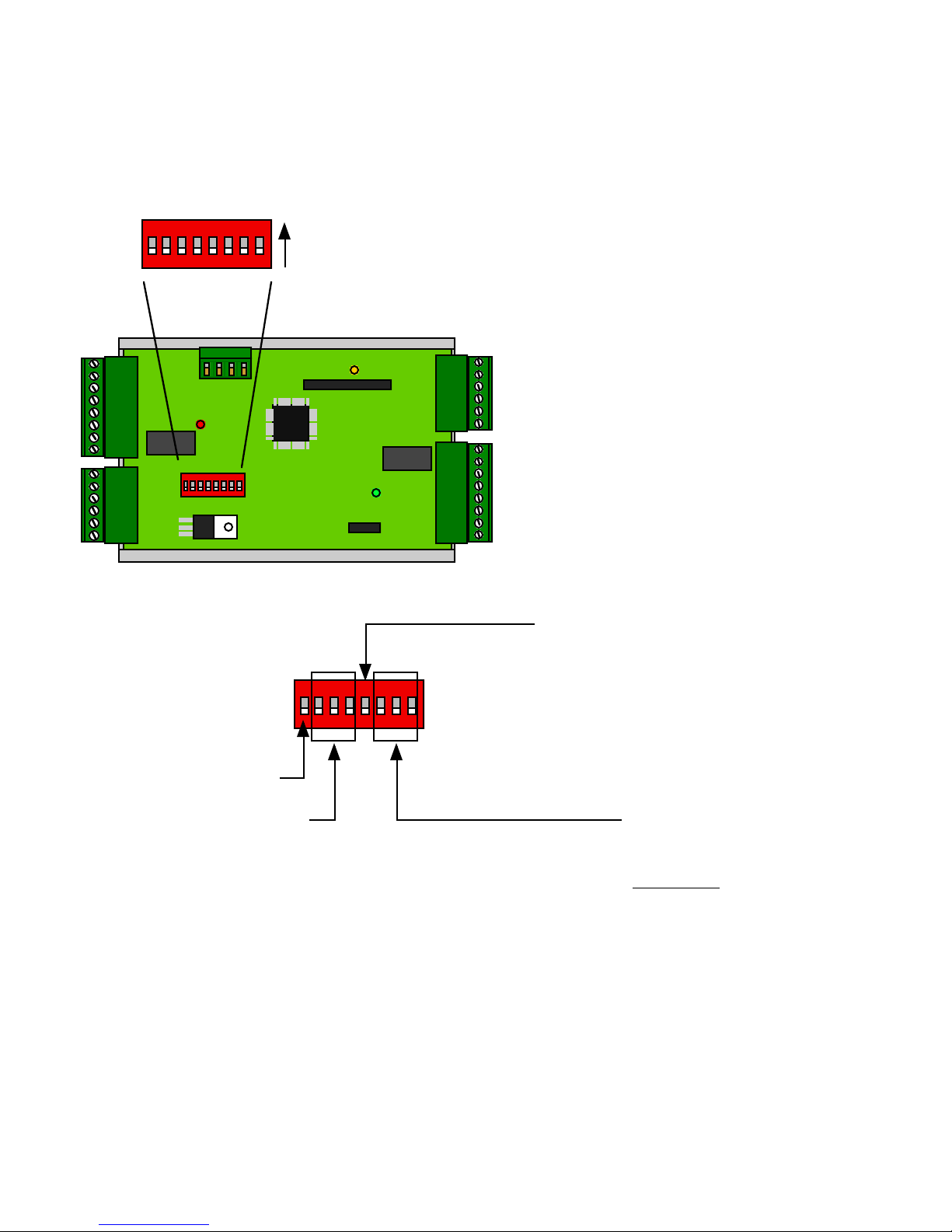
CENTRAL UNIT ONLY
Dip switch #5 is ON
Door Strike relay does NOT follow LED
(Auxiliary setting)
1234567
8
On
Off
1234567
8
Service/Config Mode
Reserved Setting
2,3,4 OFF
Reader Format
Switch
6 7 8
0
1 x
2 x
3 x x
4 x
5 x x
6 x x
7 x x x
Wiegand
Wiegand / No Filter
Strobed Rising Edge (MR-5)
Strobed Rising Edge (Dorado 644)
Strobed Rising (Mag-Tek)
Strobed Falling Edge
Reserved
Reserved
x = ON
All settings except Switch 5 are the same for Central and Remote units.
DIP Switch Settings- Quick Reference

©2008 Cypress Computer Systems,Inc. • www.cypressworld.com 3/4/08 Page 4
FCC Part 15 Notice of Compliance
This device operates under Part 15 of the FCC rules. There are several requirements that
must be met to maintain compliance.
These devices can only be used with approved antennas.
Warning: This equipment has been approved for mobile applications where equipment should be
used at distances greater tahn 20 cm from the human body (with the exception of hands, feet, wrists,
and ankles). Operation at distances of less than 20 cm is strictly prohibited and requires additional SAR
testing.
This equipment has been tested and found to comply with the limits for a Class A digital device,
pursuant to part 15 of the FCC Rules. These limits are designed to provide reasonable protection
against harmful interference in a commercial installation. This equipment generates, uses, and can
radiate radio frequency energy and, if not installed and used in accordance with the instructions, may
cause harmful interference to radio communications. However, there is no guarantee that interference
will not occur in a particular installation. If this equipment does cause harmful interference to radio or
television reception, which can be determined by turning the equipment off and on, the user is
encouraged to try to correct the interference by one or more of the following measures:
- Reorient or relocate the receiving antenna
- Increase the separation between the equipment and receiver.
- Connect the equipment into an outlet on a circuit different from that to which the receiver is
connected.
- Consult the dealer or an experienced radio/TV technician for help.
This device complies with part 15 of the FCC Rules.
Operation is subject to the following two conditions:
(1) This device may not cause harmful interference, and
(2) this device must accept any interference received,
including interference that may cause undesired operation.
FCC Part 15 COMPLIANCE

©2008 Cypress Computer Systems,Inc. • www.cypressworld.com 3/4/08 Page 5
The Cypress Duprex RF is the newest member of the Suprex family of products.
The Duprex RF 5500 series supports a wide range of additional features from previous versions of
the Suprex RF family.
Additional features:
-- DES56 Encryption for secure communications
--No channel selection is required as the units are preconfigured at the factory.
--Diagnostic mode for setup and configuration
--“Quiet” RF protocol to conserve bandwidth and power
--Field configurable reader formats
--Additional indicators for determining operational status of the unit
Initial setup and configuration.
The Duprex RF unit operates as a matched pair of units that share the same communication channel.
Each pair is configured at the factory to operate without the need to set channels.
A matched pair will have the same serial number.
Each pair communicates using an intelligent addressing algorithm. This allows multiple pairs of units
to operate in the same environment without interfering with each other.
The #1 DIP switch is the Setup/Config switch. This switch has multiple functions. With the switch in
the OFF position, the unit operates in Normal mode. When the switch is in the ON position, the unit is
in the Service / Configuration mode.
When the switch is set to Service / Configuration mode , the unit will operate using a diagnostic
protocol that will show communication activity between the Central and Remote units (The Yellow
communication LED will flash rapidly).
When switching from Service / Configuration mode to Normal mode, the unit will reset and run with a
“Quiet” RF protocol.
This Quiet protocol maintains communication between the Central and Remote units as necessary for
I/O, Badge Activity, and Supervision without requiring continuous use of the RF channel.
Initial Setup;
This manual will cover the basic installation procedure for a typical Duprex RF system.
The first step will be to configure and test the units at a bench top location where both the Central and
Remote units are close together. This will allow the setup and configuration process to occur with both
sides of the operation in view.

©2008 Cypress Computer Systems,Inc. • www.cypressworld.com 3/4/08 Page 6
Enclosure:
Weatherproof Polystyrene
10”H x 7” W x 3.5”
Environmental Specifications:
Enclosure NEMA 4X Rating
Temperature Range -40 to 85 C
Electrical Specifications:
(Each Unit)
Supply Voltage 8-24VDC
Current 500mA
Wall plug power supply included
Radio Specifications:
Frequency 900 MHz ISM band
Type Frequency Hopping Spread Spectrum
Transmit Power 100mW
Receive Sensitivity -110 dBm
Interference Rejection 70dB
Antenna Options and typical range:
Internal - Up to 2500 feet
1/2 wave whip- up to 1 Mile
6 element Yagi - Up to 5 miles.
Distances given are typical line of sight. Actual distance will vary
depending upon terrain, RF environment, and height of antenna.
Duprex Specifications:
Wiegand and Magstripe formats field selectable
See Duprex manual for details.
Specifications:

©2008 Cypress Computer Systems,Inc. • www.cypressworld.com 3/4/08 Page 7
BENCH TEST UNITS BEFORE INSTALLATION
Before installing the units in the field they should be assembled and tested at a convenient “Bench top”
location. This will make it easier to verify / change settings and check operation when both units are
visible at the same time.
It is also a chance to become familiar with the system if this is the first time using the Duprex system. It is
much more difficult to configure and test the units when they are several thousand feet apart.
The units as shipped are configured as a matched pair and are ready to plug in and operate.
Both units need to have the antenna and a suitable power supply installed.
Remove covers from units and check interior for any shipping damage. Remove any
packing material if present.
Unpack Units

©2008 Cypress Computer Systems,Inc. • www.cypressworld.com 3/4/08 Page 8
The RF units are capable of operating with multiple pairs of units in the same environment. Units on
different channels can operate in the same area with minimal interference to each other.
Unit channel selection is made at the factory and no field settings are necessary.
Up to 8 pairs of units can operate in the same area. . A serial number sticker will be present on the
unit to indicate the paired units. Units matched as a pair will have the same serial number.
During initial setup it is helpful to use the Setup/Config mode. This allows a relative indication of the
radio transmission and reception between units.
Here follows a description of the Setup / Config mode.
Setup / Config mode:
By setting DIP switch 1 to the ON position, the unit is placed in Setup / Config mode. This switch
change can be made at any time. When the switch position is changed, the unit will reset and restart
in the new mode. This is helpful for setup and diagnostic purposes.
In Normal operational mode (DIP switch #1 OFF) the units will remain quiet unless there is a
status change, and will slowly poll each other about every 10 to 15 seconds to check the link
integrity.
The Setup / Config mode places the units in rapid polling sequence to allow troubleshooting and
setup of the communication link.
The Duprex RF units use a quiet protocol when operating in normal mode. Communication between
the Central and Remote unit only occurs when an event requires data transmission or contact needs
to be made to maintain supervision. The RF channel remains quiet most of the time.
During setup or troubleshooting it may be necessary to observe the communication link between the
Central and Remote units. The rapid polling used in the Setup / Config mode can help indicate
whether the units can “See” each other.
BENCH TEST UNITS - Configuration Mode
©2008 Cypress Computer Systems,Inc. • www.cypressworld.com 3/4/08 Page 9
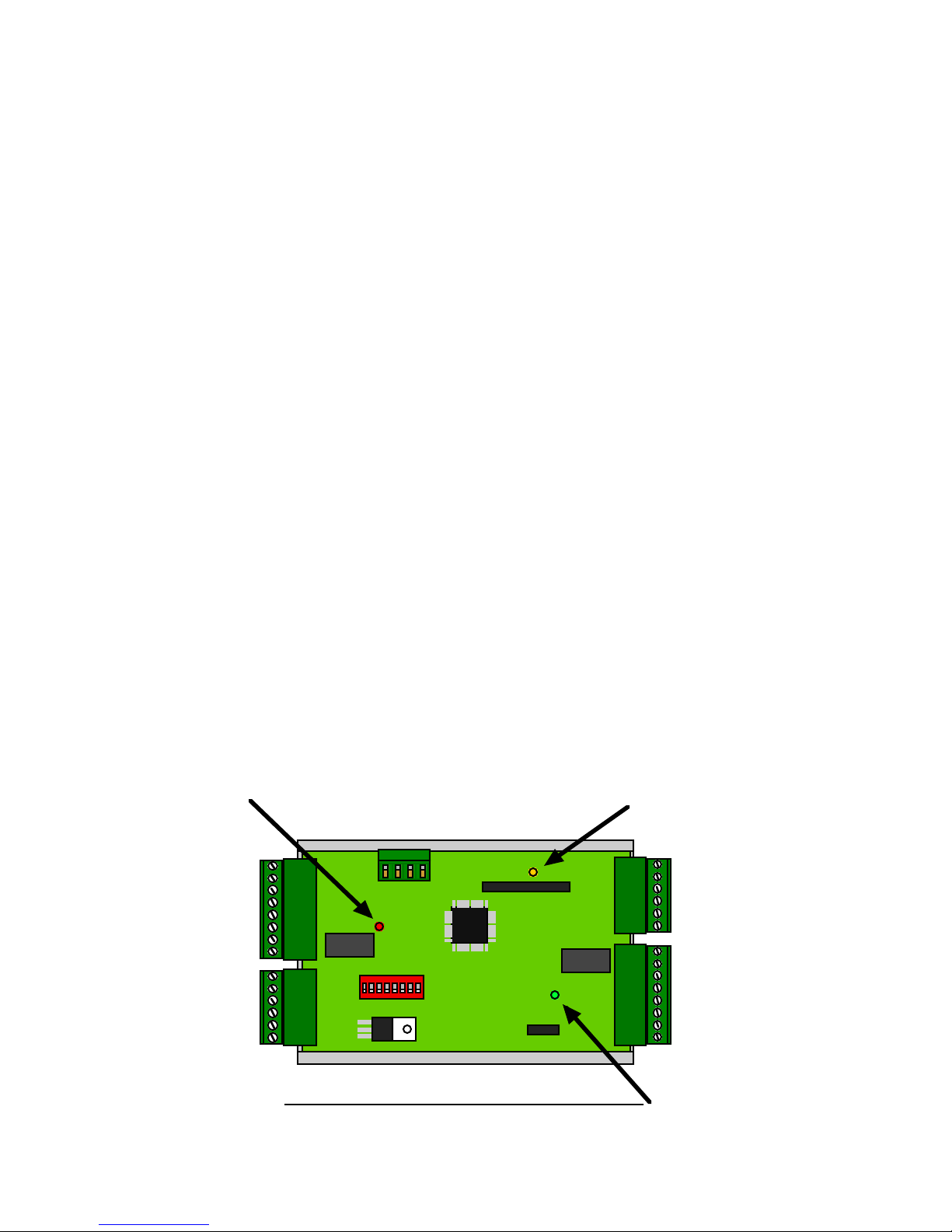
Communication
Activity LED
(Amber)
Power LED (Green)
Diagnostic LED (Red/Green/Yellow multi color)
LED Indicator Location reference
Testing the units under controlled conditions before installation will greatly simplify the installation
procedure.
Quick bench test procedure:
Plug in the Remote unit power supply.
The Green power LED should illuminate
The Amber com LED should be off
The Diagnostic LED should illuminate a solid red color.
Plug in the Central unit power supply.
The Green power LED should illuminate.
The Amber com LED should flash and then go out.
After a short delay, the Diagnostic LEDs on both the Central and Remote units should flash
green on and off about once per second.
Now turn DIP Switch #1 ON on both the Central and Remote units.
The Amber LED on both the Central and Remote units should flash 2-3 times per second.
Disconnect power to the Remote unit
The Central unit alarm relay should activate, and the diagnostic LED should indicate RED.
Turn off DIP Switch #1 on both units to place them in normal operational mode.
BENCH TEST UNITS

©2008 Cypress Computer Systems,Inc. • www.cypressworld.com 3/4/08 Page 10
With the units a the rapid polling (Setup/Config) mode, the Amber com LED can be used to determine
whether the units are in communication with each other.
Further Bench testing:
If the reader and panel are conveniently located, it is advisable to connect the reader to the Remote unit,
and the panel to the Central unit and test the units as a complete system. Use a test badge that has been
programmed into the panel to test operation. See the DPX-7000 manual for electrical connections and
further explanation of connecting readers and panels to the Duprex units.
Remember to disconnect any power supplies if you will be using the panel power supply or other
auxiliary supply. Only one power supply should be used for each unit.
Connect the Central unit to the Access Control Panel (ACP)
Connect the reader to the Remote unit.
Provide power to both units and verify communication.
Use a test badge to verify operation of panel, reader, and connections.
Doing the setup and initial testing with both the Central and Remote units when they are close together will
save time if there are any problems that need to be corrected or installation issues that need to be clarified.
Once the connection, setup, and configuration have been completed with both units, field installation and
final commissioning can be done.
BENCH TEST UNITS - Additional configuration information

©2008 Cypress Computer Systems,Inc. • www.cypressworld.com 3/4/08 Page 11
Mounting the units.
A site evaluation should have determined the optimal locations for the Central and Remote
units, the type of antennas that would be needed, and the frequency band to be used.
(See Cypress Application Note “Site Evaluation for Duprex RF products”).
This section of the document covers units that utilize the enclosure mounted1/2 wave whip
antenna. For other types of antennas there will be specific documentation to cover their
different installation issues.
We are now ready to physically mount the units and make the electrical connections to
complete the installation.
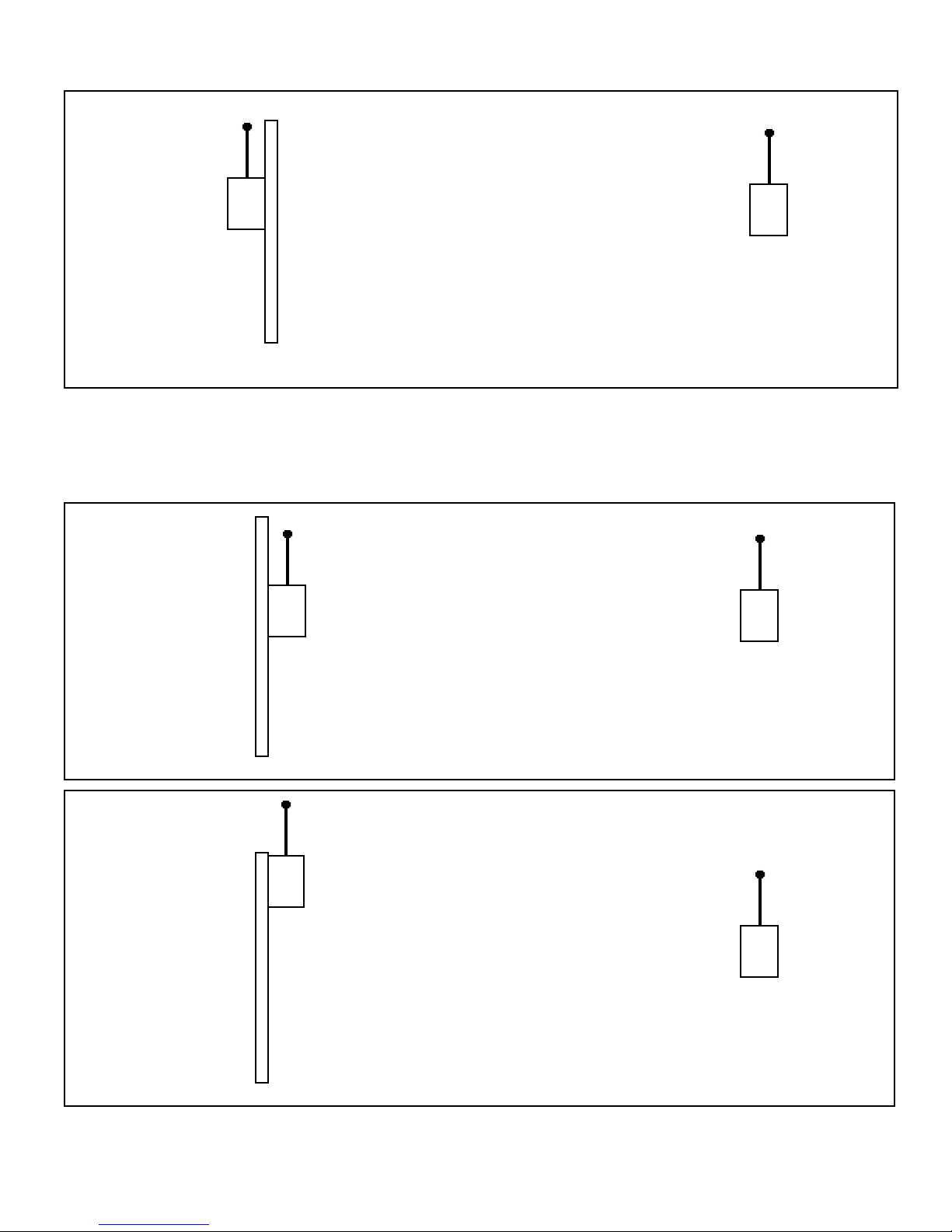
The units should be mounted so that the length dimension of the antennas are in the same
plane. The orientation of the antenna will determine what is referred to as the polarization of
the signal. Significant reduction in range can result if the units are not of the same polarity.
See below.
Both Central and Remote units are arranged so the antennas are parallel in direction. As shown in this
illustration we would say they are both vertically polarized. Since the polarity is in the same direction,
the signal strength would be maximized.
In this instance one of the units is vertically polarized, and the other is horizontally polarized. The signal
would be greatly reduced thereby reducing the maximum distance between units.
The installer should make sure that both units are mounted so that the polarization will be the same for
both units.
In all cases the antennas MUST be mounted at a distance of 20 cm or
greater
©2008 Cypress Computer Systems,Inc. • www.cypressworld.com 3/4/08 Page 12
Mounting the units - Antenna Orientation
The units should be mounted in such a way that there is as clear of a path as possible between the 2
units. If mounting to a post or wall the unit should be placed where it has minimal interference with the
antenna. Maximum signal and ranges are achieved when the antenna is clear of obstructions and is
placed away from metal objects.
This orientation may reduce range. The metal pole is
placed between antenna and other unit and the antenna is
close to metal.
Better, improved range. Antenna has line of sight to other
unit. Proximity to metal pole may reduce range.
Best, antenna has line of sight to other unit and is clear
of adjacent metal objects.
In all cases the antennas MUST be mounted at a distance of 20 cm or greater from any nearby persons

©2008 Cypress Computer Systems,Inc. • www.cypressworld.com 3/4/08 Page 13
The other mounting method utilizes internal knockouts on the back of the unit. In some installations it
may be easier to use these knockouts.
Screw knockout
Knockout removed by pressing
on it with screwdriver blade. Be
careful not to damage interior
components.
Screw placed in knockout.
Knockout end seal tabs
Seal tab placed over knockout
after screw has been fastened
in place.
Inside Knockout Mounting Screws
Mounting the units-Hardware

©2008 Cypress Computer Systems,Inc. • www.cypressworld.com 3/4/08 Page 14
Mounting the units-Hardware
There are two sets of mounting holes provided.
The first set of mounting holes consists of the four corner channels that are also used to mount the
cover plate screws.
Four mounting screws can be threaded through the corner holes. This also is advantageous in
that the screws do not breach any of the environmental seals.
Mounting screws are not included due to the infinite variety of potential mounting surfaces.
Select a type of mounting screw based on the type of material.
Placement of screw in corner channel.
Screw placed into channel.
Fasten screws in place with long handled
screwdriver.
Corner Channel Mounting Screws

©2008 Cypress Computer Systems,Inc. • www.cypressworld.com 3/4/08 Page 15
The Green power LED should always be illuminated if power is applied. If this LED is not illuminated
there is a power problem, or a problem with the unit.
It is a good idea to switch both Central and Remote units to Service / Config mode to verify the field
installation.
Both units should be communicating. See bench test sequence for details for LED indicators when in
Service / Config mode.
Check operation of Badge reader, LED and other I/O that is used in the installation while in Service /
Config mode.
Once operation has been verified in Service / Config mode then the units can be placed in Normal Run
mode. The Amber com LED will flash infrequently in Normal mode. It should flash each time a badge is
swiped or any of the I/O changes status.
The Central unit diagnostic LED will be Red when the units are not communicating. This may be
happen when the Central unit powers up without the Remote unit having power. Once both units are
powered up the diagnostic LEDs should both enter a flashing green on and off mode. This should
occur within 30 seconds of both units having power applied in Normal mode.
Check operation of Badge reader, LED and other I/O in Normal mode.
Insert cover mounting screws and tighten.
Installation is complete.
Final Checkout
 Loading...