

Page 1

Solar-Powered BLE Sensor Beacon
Reference Design Kit Guide
CYALKIT-E02
Doc. No. 002-11317 Rev. *C
Cypress Semiconductor
198 Champion Court
San Jose, CA 95134-1709
www.cypress.com
Page 2

Copyrights
© Cypress Semiconductor Corporation, 2016-2017. This document is the property of Cypress Semiconductor Corporation
and its subsidiaries, including Spansion LLC (“Cypress”). This document, including any software or firmware included or
referenced in this document (“Software”), is owned by Cypress under the intellectual property laws and treaties of the United
States and other countries worldwide. Cypress reserves all rights under such laws and treaties and does not, except as
specifically stated in this paragraph, grant any license under its patents, copyrights, trademarks, or other intellectual property
rights. If the Software is not accompanied by a license agreement and you do not otherwise have a written agreement with
Cypress governing the use of the Software, then Cypress hereby grants you a personal, non-exclusive, nontransferable
license (without the right to sublicense) (1) under its copyright rights in the Software (a) for Software provided in source code
form, to modify and reproduce the Software solely for use with Cypress hardware products, only internally within your
organization, and (b) to distribute the Software in binary code form externally to end users (either directly or indirectly through
resellers and distributors), solely for use on Cypress hardware product units, and (2) under those claims of Cypress’s patents
that are infringed by the Software (as provided by Cypress, unmodified) to make, use, distribute, and import the Software
solely for use with Cypress hardware products. Any other use, reproduction, modification, translation, or compilation of the
Software is prohibited.
TO THE EXTENT PERMITTED BY APPLICABLE LAW, CYPRESS MAKES NO WARRANTY OF ANY KIND, EXPRESS OR
IMPLIED, WITH REGARD TO THIS DOCUMENT OR ANY SOFTWARE OR ACCOMPANYING HARDWARE, INCLUDING,
BUT NOT LIMITED TO, THE IMPLIED WARRANTIES OF MERCHANTABILITY AND FITNESS FOR A PARTICULAR
PURPOSE. To the extent permitted by applicable law, Cypress reserves the right to make changes to this document without
further notice. Cypress does not assume any liability arising out of the application or use of any product or circuit described in
this document. Any information provided in this document, including any sample design information or programming code,
is provided only for reference purposes. It is the responsibility of the user of this document to properly design, program, and
test the functionality and safety of any application made of this information and any resulting product. Cypress products are
not designed, intended, or authorized for use as critical components in systems designed or intended for the operation of
weapons, weapons systems, nuclear installations, life-support devices or systems, other medical devices or systems
(including resuscitation equipment and surgical implants), pollution control or hazardous substances management, or other
uses where the failure of the device or system could cause personal injury, death, or property damage (“Unintended Uses”).
A critical component is any component of a device or system whose failure to perform can be reasonably expected to cause
the failure of the device or system, or to affect its safety or effectiveness. Cypress is not liable, in whole or in part, and you
shall and hereby do release Cypress from any claim, damage, or other liability arising from or related to all Unintended Uses
of Cypress products. You shall indemnify and hold Cypress harmless from and against all claims, costs, damages, and
other liabilities, including claims for personal injury or death, arising from or related to any Unintended Uses of Cypress
products.
Cypress, the Cypress logo, Spansion, the Spansion logo, and combinations thereof, WICED, PSoC, CapSense, EZ-USB,
F-RAM, and Traveo are trademarks or registered trademarks of Cypress in the United States and other countries. For a
more complete list of Cypress trademarks, visit cypress.com. Other names and brands may be claimed as property of their
respective owners.
CYALKIT-E02 Solar-Powered BLE Sensor Beacon Reference Design Kit Guide, Doc. No. 002-11317 Rev. *C 2
Page 3

Contents
Safety Information .................................................................................................................................................................. 5
Regulatory Compliance ................................................................................................................................................... 5
General Safety Instructions ............................................................................................................................................. 6
1. Introduction .................................................................................................................................................................... 7
1.1 Kit Introduction ....................................................................................................................................................... 7
1.2 Block Diagrams ..................................................................................................................................................... 8
1.3 Features ................................................................................................................................................................ 9
2. Software Installation ................................................................................................................................................... 11
2.1 Install Cypress BLE-Beacon Software ................................................................ ................................................. 11
2.2 Install RDK Software ........................................................................................................................................... 12
2.3 Uninstall Software ................................................................................................................................................ 14
2.4 PSoC Creator™ ................................................................................................................................................... 14
3. Getting Started ............................................................................................................................................................. 15
3.1 WSN Operation with PC ...................................................................................................................................... 15
3.2 WSN Operation with Mobile Device ..................................................................................................................... 22
3.3 Configuring Solar BLE Sensor ............................................................................................................................. 26
3.4 Serial Command List ........................................................................................................................................... 31
3.5 Eddystone-URL Configuration Service ................................................................................................................ 40
3.6 Note About Validators .......................................................................................................................................... 40
4. Program and Debug .................................................................................................................................................... 42
4.1 KitProg ................................................................................................................................................................. 42
4.2 Programming and Debugging .............................................................................................................................. 42
4.3 Updating KitProg Firmware.................................................................................................................................. 47
5. Reference Design ........................................................................................................................................................ 48
5.1 Hardware Description .......................................................................................................................................... 48
5.2 Firmware Description ........................................................................................................................................... 56
5.3 BLE Beacon Format ............................................................................................................................................ 67
5.4 Eddystone Format ............................................................................................................................................... 69
6. Hardware ...................................................................................................................................................................... 71
6.1 Solar BLE Sensor ................................................................................................................................................ 71
6.2 Debug Board ....................................................................................................................................................... 77
CYALKIT-E02 Solar-Powered BLE Sensor Beacon Reference Design Kit Guide, Doc. No. 002-11317 Rev. *C 3
Page 4

Contents
Appendix A. Advanced Topics ........................................................................................................................................ 82
A.1 Battery Input Operation ....................................................................................................................................... 82
A.2 Charging the Supercapacitor ............................................................................................................................... 83
A.3 Equivalent Series Resistance of the Supercapacitor ........................................................................................... 84
A.4 Diode Connection Between Solar Cell and VDD ................................................................................................. 85
Appendix B. Solar BLE Sensor Enclosure ..................................................................................................................... 87
B.1 Solar BLE Sensor Enclosure ............................................................................................................................... 87
B.2 How to Install the Board in the Enclosure ............................................................................................................ 88
Revision History ................................................................................................................................................................... 90
CYALKIT-E02 Solar-Powered BLE Sensor Beacon Reference Design Kit Guide, Doc. No. 002-11317 Rev. *C 4
Page 5

Safety Information
<
The CYALKIT-E02 Solar-Powered BLE Sensor Beacon RDK as shipped from the factory has been verified to
meet the requirements of CE as a Class A product.
The CYALKIT-E02 Solar-Powered BLE Sensor Beacon RDK contains electrostatic discharge
(ESD) sensitive devices. Electrostatic charges readily accumulate on the human body and any
equipment and can discharge without detection. Permanent damage may occur to devices
subjected to high-energy discharges. Proper ESD precautions are recommended to avoid
performance degradation or loss of functionality. Store unused CYALKIT-E02 boards in the
protective shipping package.
End of Life/Product Recycling
The end of life of this kit is five years after the date of manufacture mentioned on the back of the
box. Contact your nearest recycler to discard the kit.
Regulatory Compliance
The CYALKIT-E02 Solar-Powered Bluetooth Low Energy (BLE) Sensor Beacon Reference Design Kit (RDK) is intended for
use as a development platform for hardware or software in a laboratory environment. The board is an open system design,
which does not include a shielded enclosure. This may cause interference with other electrical or electronic devices in close
proximity. In a domestic environment, this product may cause radio interference. In this case, the user may be required to take
adequate preventive measures. Also, the board should not be used near any medical equipment or RF devices.
Attaching additional wiring to this product or modifying the product operation from the factory default may affect its
performance and cause interference with other apparatus in the immediate vicinity. If such interference is detected, suitable
mitigating measures should be taken.
CYALKIT-E02 Solar-Powered BLE Sensor Beacon Reference Design Kit Guide, Doc. No. 002-11317 Rev. *C 5
Page 6

Safety Information
General Safety Instructions
ESD Protection
ESD can damage boards and their associated components. Cypress recommends that you perform procedures only at an
ESD workstation. If one is not available, use appropriate ESD protection by wearing an antistatic wrist strap attached to
chassis ground (any unpainted metal surface) on your board when handling parts.
Handling Boards
CYALKIT-E02 boards are sensitive to ESD. Hold the board only by its edges. After removing the board from its box, place it on
a grounded, static-free surface. Use a conductive foam pad, if available. Do not slide the board over any surface.
CYALKIT-E02 Solar-Powered BLE Sensor Beacon Reference Design Kit Guide, Doc. No. 002-11317 Rev. *C 6
Page 7
1. Introduction
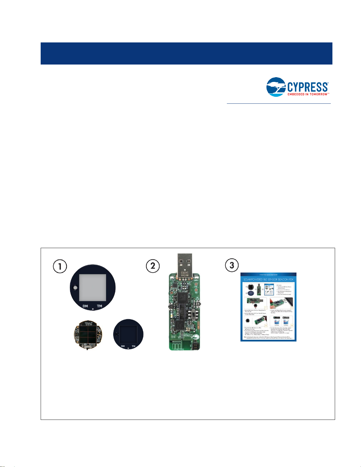
,
1. Solar-Powered BLE Sensor Beacon (Solar BLE Sensor)
- Board + Enclosure
2. BLE-USB Bridge and Debug Board (Debug Board)
3. Quick Start Guide
+
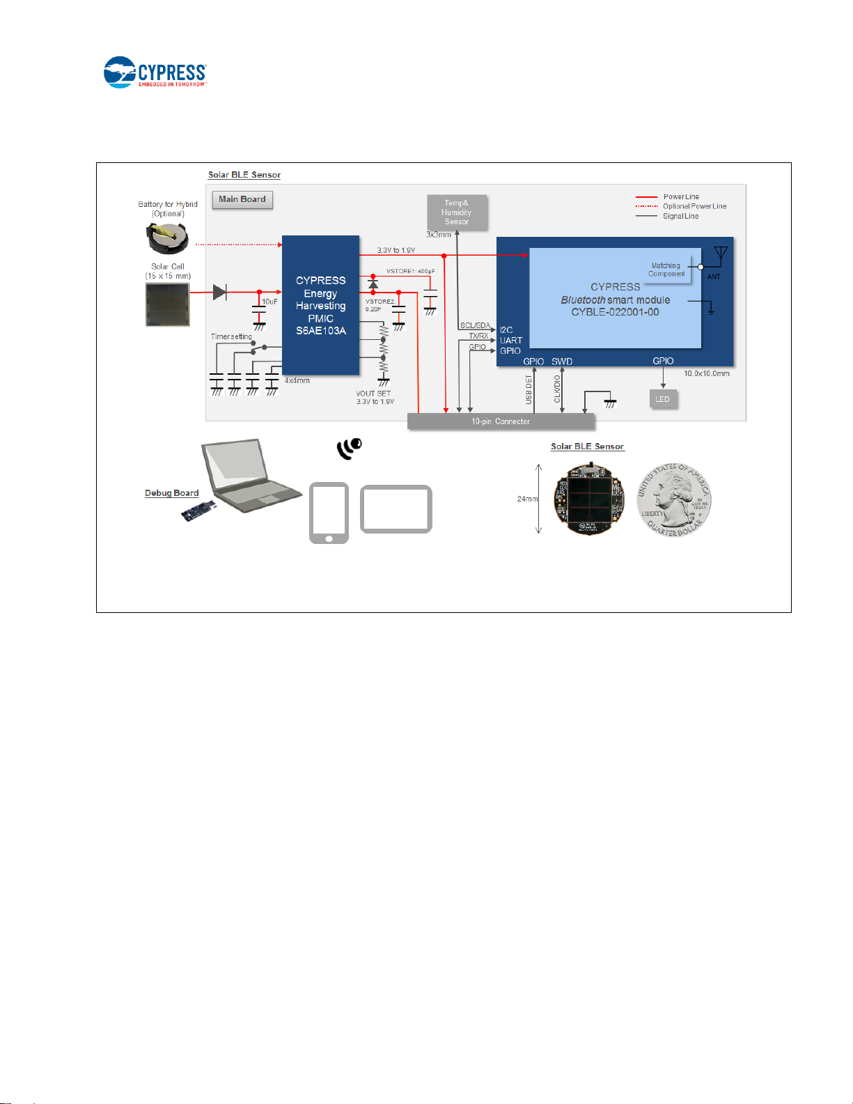
Thank you for your interest in the CYALKIT-E02 Solar-Powered BLE Sensor Beacon RDK. The Solar-Powered BLE Sensor
Beacon RDK provides an easy-to-use platform for the development of a tiny solar-powered IoT device with BLE wireless
connectivity. The RDK consists of a Solar BLE Sensor and a Debug Board. The Solar BLE Sensor is based on Cypress’s
energy harvesting power management IC (PMIC) S6AE103A and EZ-BLE products. The objective of this RDK is to provide a
fully functional battery-less wireless sensor node (WSN). The Solar BLE Sensor will be enclosed in a casing to automatically
transmit temperature and humidity sensor data in an office lighting environment. The Debug Board is based on Cypress’s
PRoC™ BLE and PSoC® 5LP products. It can be connected to a host (PC) that supports the Debug Board and on-chip
debugging via a USB interface.
This kit guide explains how to set up and use the RDK. Be sure to read it before using the product. For questions, please
consult with sales or support representatives.
Note: All information included in this document is current as of the date it was issued. Such information is subject to change
without any prior notice. Please confirm the latest relevant information with the sales representative.
1.1 Kit Introduction
CYALKIT-E02 Solar-Powered BLE Sensor Beacon Reference Design Kit Guide, Doc. No. 002-11317 Rev. *C 7
Figure 1-1. Kit Contents
Page 8
Introduction
PC based on Windows 7/8.1/10
iOS 8 or newer
Android 4.4 or newer
1.2 Block Diagrams
Figure 1-2. Block Diagram of Solar BLE Sensor
CYALKIT-E02 Solar-Powered BLE Sensor Beacon Reference Design Kit Guide, Doc. No. 002-11317 Rev. *C 8
Page 9
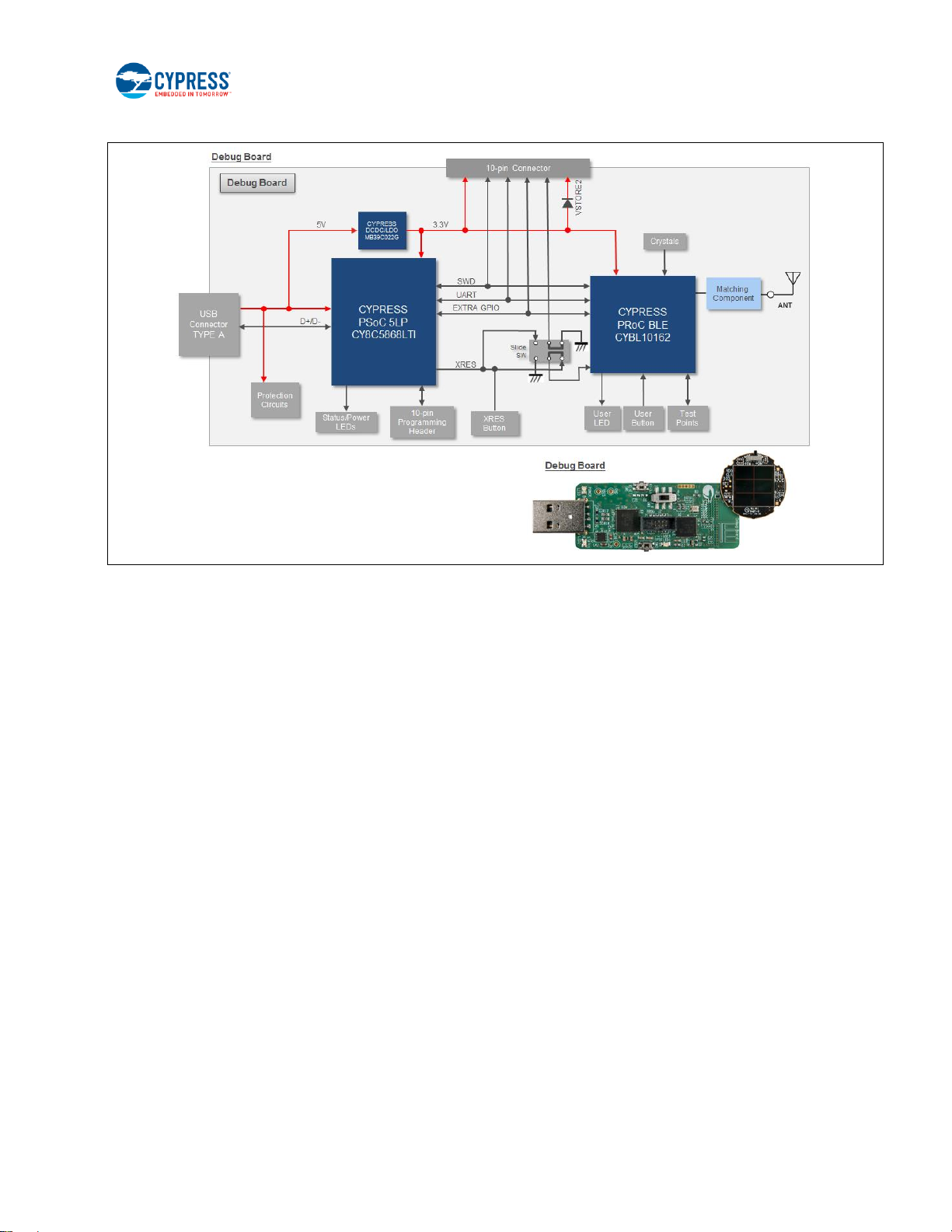
Introduction
Figure 1-3. Block Diagram of Debug Board
1.3 Features
The Solar-Powered BLE Sensor Beacon RDK provides everything needed to develop a light-powered sensor node that
transmits sensor data using Bluetooth Low Energy (BLE):
Tiny solar-powered BLE sensor board (circle with 24-mm diameter, same size as a 25-cent coin)
Operates using light energy harvested (>100 lux) by the included solar cell
Supports BLE communication with a PC through the provided Debug Board that is preprogrammed with custom firmware
for this kit
Supports BLE communication with a mobile device (iOS 8 or newer / Android 4.4 or newer)
Includes firmware that supports a BLE Beacon transmission with temperature and humidity data
Energy harvesting PMIC S6AE103A that supports the following applications:
□ Demo mode, transmitting sensor data at 3- to 60-second intervals (without charging to a supercapacitor)
□ Timer mode, transmitting sensor data at 5-minute intervals while charging to the supercapacitor
□ Transmitting data at over 30 hours without ambient light (when mode is set to Timer mode and supercapacitor is
fully charged)
Solar BLE Sensor that can support the following:
□ Selection of mode using a slide switch (Demo or Timer mode)
□ Programming and debugging of the EZ-BLE module via the Debug Board
□ Parameter setting of the BLE Beacon via the Debug Board
□ Charging of surplus solar energy to a 0.2-F supercapacitor (Timer mode)
□ Charging of the supercapacitor via the Debug Board using USB bus power
□ Temperature and humidity digital sensor
CYALKIT-E02 Solar-Powered BLE Sensor Beacon Reference Design Kit Guide, Doc. No. 002-11317 Rev. *C 9
Page 10

Introduction
□ Expandable interface via 10-pin connector (GPIO)
□ Test pads for power, ground, primary battery input, and SWD interface for programming
Debug board that can support the following:
□ Debug board for receiving BLE data
□ Selecting the programming mode using a slide switch (EZ-BLE on Solar BLE Sensor or PRoC BLE on Debug
Board)
□ Connector for Solar BLE Sensor (power, SWD, UART, USB detect, charging supercapacitor, and GPIO)
□ Connector for programming PSoC 5LP (KitProg)
□ Parameter setting of Solar BLE Sensor via USB-to-UART bridge on KitProg
□ Reset button for EZ-BLE and PRoC BLE
□ User button for PRoC BLE
□ LEDs for User, Status and USB power
□ Test pads for power, ground and expandable GPIO
Includes reference schematic, BOM list, layout, and sample firmware for easy design
Uses the following Cypress devices:
□ S6AE103A ultra-low-power energy harvesting PMIC
□ CYBLE-022001-00 EZ-BLE PRoC module
□ CYBL10162-56L PRoC BLE IC
□ CY8C5868L PSoC 5LP for KitProg
□ MB39C022G LDO
CYALKIT-E02 Solar-Powered BLE Sensor Beacon Reference Design Kit Guide, Doc. No. 002-11317 Rev. *C 10
Page 11
2. Software Installation
This section describes how to install the software.
2.1 Install Cypress BLE-Beacon Software
Follow these steps to install the Cypress BLE-Beacon software:
1. Download and install the Cypress BLE-Beacon software from www.cypress.com/CypressBLE-Beacon-PC. The
software is available in two different formats for download:
Cypress® BLE-Beacon™ PC: This executable file installs only the software contents, which include software files,
and user documents. This package can be used if all the software prerequisites are installed on your computer.
Cypress® BLE-Beacon™ PC ISO (Create CD): This file is a complete package, stored in a CD-ROM image format
that can be used to create a CD, or extract using ISO extraction programs, such as WinZip or WinRAR. This file
includes all the required software and user documents.
2. Run Install Cypress BLE-Beacon to start the installation, as shown below.
3. Select the folder to install the Cypress BLE-Beacon–related files. Choose the directory and click Next.
4. The Cypress BLE-Beacon installer automatically installs the required software, if it is not present on your computer. The
Setup installer directs you to download the required software from the Internet.
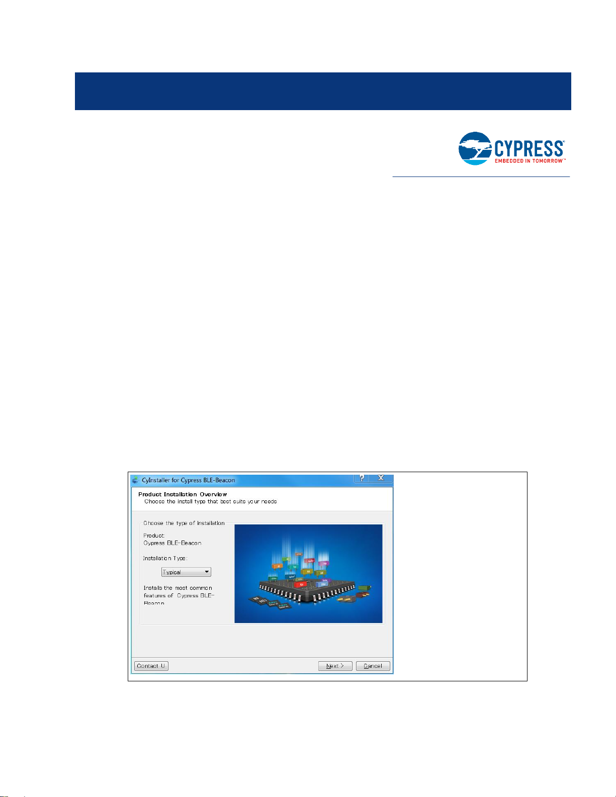
5. Choose the Typical/Custom/Complete installation type in the Product Installation Overview window. Click Next
after you select the installation type.
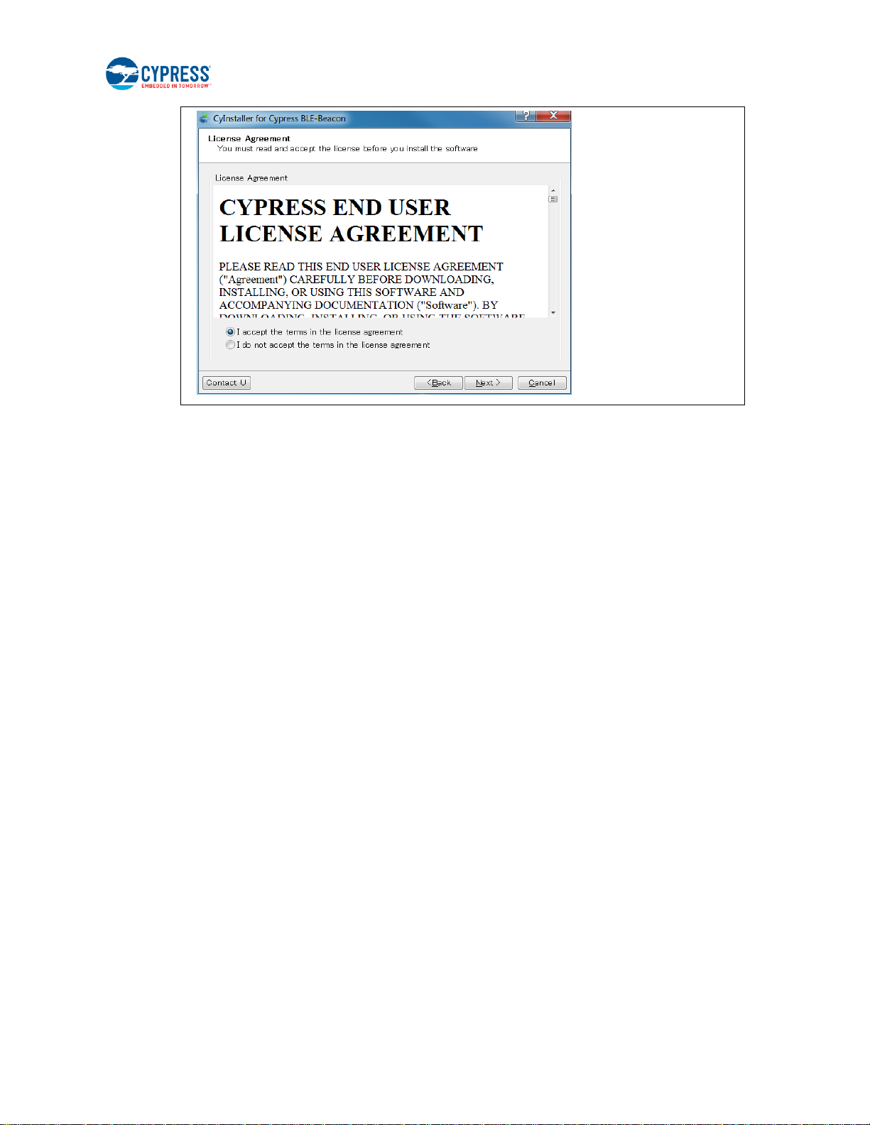
6. Read the Cypress End User License Agreement and make a selection based on the terms of the license agreement.
Click Next to continue the installation.
CYALKIT-E02 Solar-Powered BLE Sensor Beacon Reference Design Kit Guide, Doc. No. 002-11317 Rev. *C 11
Page 12
Software Installation
7. When the installation begins, a list of packages appears on the installation page. A green check mark appears next to
each package after successful installation.
8. Click Finish to complete the Cypress BLE-Beacon installation.
9. Enter your contact information or select the Continue Without Contact Information check box. Click Finish to
complete the Cypress BLE-Beacon installation.
10. After the installation is complete, the kit contents are available at the following location:
<Install directory>\Cypress BLE-Beacon
Default location (Example: Windows 7)
64-bit: C:\Program Files (x86)\Cypress\Cypress BLE-Beacon
32-bit: C:\Program Files\Cypress\Cypress BLE-Beacon
2.2 Install RDK Software
Follow these steps to install the CYALKIT-E02 Solar-Powered BLE Sensor Beacon RDK software:
1. Download and install the CYALKIT-E02 software from www.cypress.com/CYALKIT-E02. The CYALKIT-E02 software is
available in three different formats for download:
□ CYALKIT-E02 Complete Setup: This installation package contains the files related to the kit. However, it does not
include the Windows Installer or Microsoft .NET framework packages. If these packages are not on your computer,
the installer directs you to download and install them from the Internet.
□ CYALKIT-E02 Only Package: This executable file installs only the kit contents, which include code examples,
hardware files, and user documents. This package can be used if all the software prerequisites are installed on your
computer.
□ CYALKIT-E02 CD ISO: This file is a complete package, stored in a CD-ROM image format that can be used to
create a CD, or extract using ISO extraction programs, such as WinZip or WinRAR. This file includes all the
required software, utilities, drivers, hardware files, and user documents.
2. Run Install CYALKIT-E02 to start the installation, as shown below.
3. Select the folder to install the CYALKIT-E02-related files. Choose the directory and click Next.
4. The CYALKIT-E02 installer automatically installs the required software if it is not present on your computer. The
CYALKIT-E02 Setup installer directs you to download the required software from the Internet.
5. Choose the Typical/Custom/Complete installation type in the Product Installation Overview window. Click Next
after you select the installation type.
CYALKIT-E02 Solar-Powered BLE Sensor Beacon Reference Design Kit Guide, Doc. No. 002-11317 Rev. *C 12
Page 13

Software Installation
6. Read the Cypress End User License Agreement and make a selection based on the terms of the license agreement.
Click Next to continue the installation.
7. When the installation begins, a list of packages appears on the installation page. A green check mark appears next to
each package after successful installation.
8. Click Finish to complete the CYALKIT-E02 installation.
9. Enter your contact information or select the Continue Without Contact Information check box. Click Finish to
complete the CYALKIT-E02 installation.
10. After the installation is complete, the kit contents are available at the following location:
<Install directory>\CYALKIT-E02 Solar-Powered BLE Sensor Beacon RDK
Default location (Example: Windows 7)
□ 64-bit: C:\Program Files (x86)\Cypress\CYALKIT-E02 Solar-Powered BLE Sensor Beacon RDK
□ 32-bit: C:\Program Files\Cypress\CYALKIT-E02 Solar-Powered BLE Sensor Beacon RDK
CYALKIT-E02 Solar-Powered BLE Sensor Beacon Reference Design Kit Guide, Doc. No. 002-11317 Rev. *C 13
Page 14

Software Installation
2.3 Uninstall Software
You can uninstall the Solar-Powered BLE Sensor Beacon RDK software and Cypress BLE-Beacon software using one of the
following methods:
Example: Windows 7
□ Go to Start > All Programs > Cypress > Cypress Update Manager; click the Uninstall button.
□ Go to Start > Control Panel > Programs and Features. Select the Solar-Powered BLE Sensor Beacon RDK program
from the list and click the Uninstall/Change button.
2.4 PSoC Creator™
PSoC Creator is a state-of-the-art, easy-to-use integrated design environment (IDE). It is a revolutionary hardware and
software co-design environment, powered by a library of preverified and precharacterized PSoC Components. With PSoC
Creator, you can:
□ Drag and drop PSoC Components to build a schematic of your custom design
□ Automatically place and route Components and configure GPIOs
□ Develop and debug firmware using the included Component APIs
PSoC Creator also enables you to tap into an entire tool ecosystem with integrated compiler chains and production
programmers for PSoC devices.
To develop firmware for the Solar-Powered BLE Sensor Beacon RDK, you must have PSoC Creator 3.3 SP2 or newer.
Download the latest version from www.cypress.com/psoccreator.
For sample firmware information for this kit, refer to section Firmware Description.
CYALKIT-E02 Solar-Powered BLE Sensor Beacon Reference Design Kit Guide, Doc. No. 002-11317 Rev. *C 14
Page 15
3. Getting Started
<
PRoC BLE
EZ-BLE
SW3
In this chapter, you will become familiar with the Solar-Powered BLE Sensor Beacon RDK by successfully establishing a BLE
sensor beacon connection between the Solar BLE Sensor operating as a wireless sensor network (WSN), a PC with the
Debug Board, and a mobile device with apps. This will also confirm that the Solar BLE Sensor, the Debug Board, your PC,
and your mobile device are operating properly.
3.1 WSN Operation with PC
In this section, you will confirm that the Solar BLE Sensor is operating as a WSN by using the software provided on your PC to
detect temperature and humidity changes.
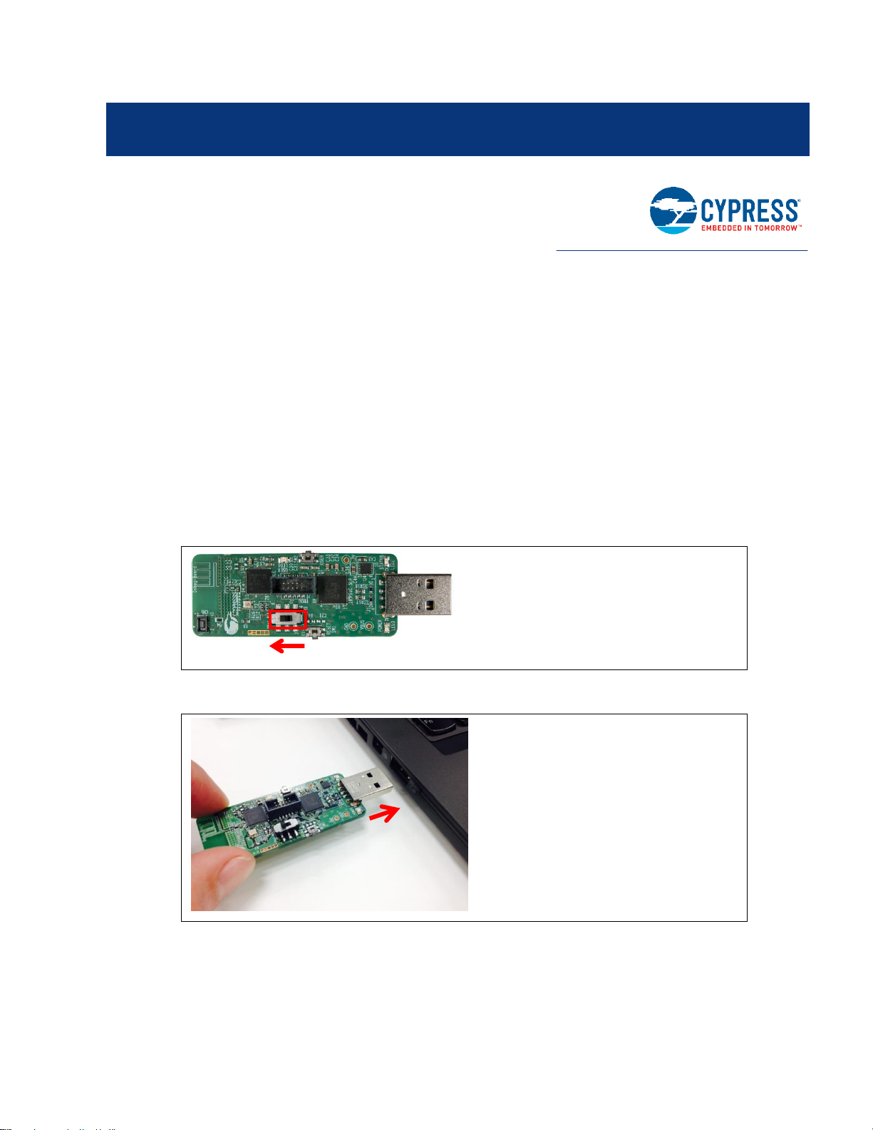
3.1.1 USB Driver Installation of Debug Board
1. Set the slide switch (SW3) on the Debug Board to the PRoC BLE side. Refer to Slide Switch for Target Device Select for
detailed information on each mode.
2. Plug the Debug Board into your computer’s USB port.
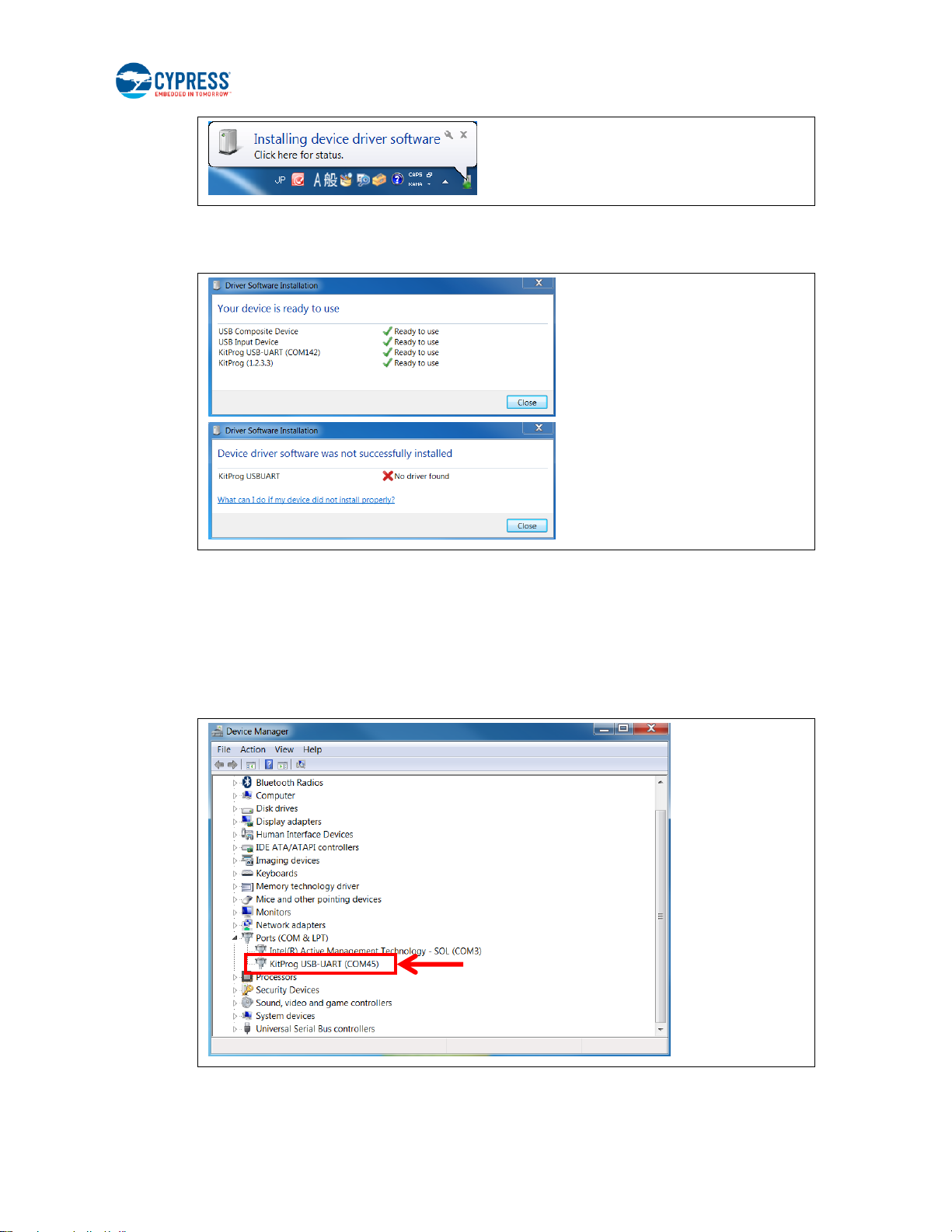
3. The driver Installation starts automatically and the following message window will appear. Click the message window
for the status.
CYALKIT-E02 Solar-Powered BLE Sensor Beacon Reference Design Kit Guide, Doc. No. 002-11317 Rev. *C 15
Page 16
Getting Started
Completed
(Go to step 5)
Failed
(Refer to USB Driver
Installation Failed)
4. Confirm that the device driver installation has successfully completed (all components are “Ready to use”). If the
installation fails, do the installation manually using a file in the “USB drivers” folder. Refer to 3.1.2 USB Driver
Installation Failed.
5. After successful device driver installation, confirm that a new COM port called “KitProg USB-UART” was added:
Open the Device Manager:
□ Windows 7: Start > Control Panel > Device Manager
□ Windows 8/8.1/10: Right-click the Start button and select Device Manager.
B. Under Ports (COM & LPT), confirm that a COM port called “KitProg USB-UART” was added. Note the COM
number (COMxx).
6. Continue as described in 3.1.3 Establishing BLE Connection.
CYALKIT-E02 Solar-Powered BLE Sensor Beacon Reference Design Kit Guide, Doc. No. 002-11317 Rev. *C 16
Page 17

Getting Started
3.1.2 USB Driver Installation Failed
If the device driver installation fails, confirm that an unconfigured KitProg USB-UART appears in the Device Manager:
1. Open the Device Manager:
Windows 7: Start > Control Panel > Device Manager
Windows 8/8.1/10: Right-click the Start button and select Device Manager.
2. Under Other devices, confirm that KitProg USB-UART appears with no associated COM port.
3. Update the USB driver software or the unconfigured “KitProg USB-UART.”
A. Click the right mouse button on “KitProg USB-UART.”
B. Select Update Driver Software….
CYALKIT-E02 Solar-Powered BLE Sensor Beacon Reference Design Kit Guide, Doc. No. 002-11317 Rev. *C 17
Page 18
Getting Started
AB C D E
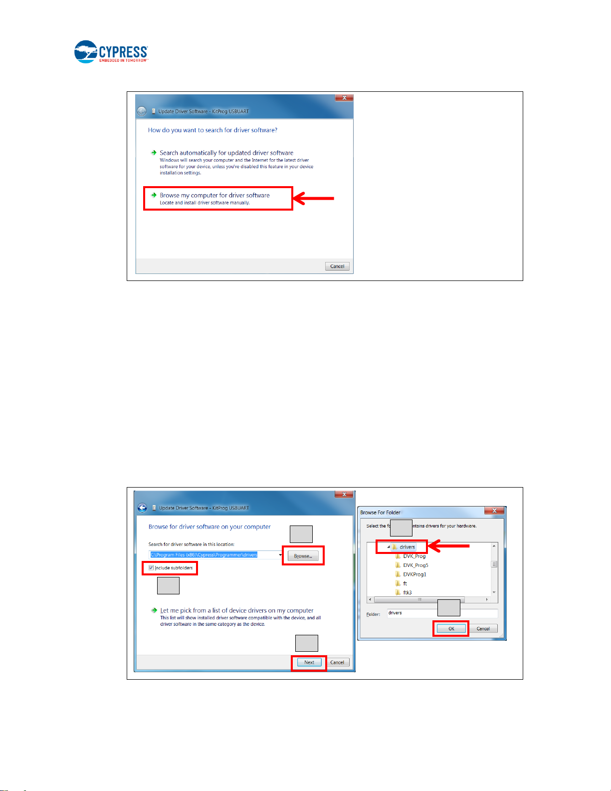
4. Select Browse my computer for driver software.
5. Search for the USB driver in the PSoC Programmer folder.
Default location (Example: Windows 7)
□ 64-bit: C:\Program Files (x86)\Cypress\Programmer\drivers
□ 32-bit: C:\Program Files\Cypress\Programmer\drivers
If there is no folder for PSoC Programmer, please download and install it from PSoC Programmer page. The
recommend version is 3.24 or later.
A. Select the Include subfolders box.
B. Click the Browse button.
C. Select the “drivers” folder of PSoC Programmer:
<Install directory>\Programmer\drivers
D. Click the OK button.
E. Click the Next button.
CYALKIT-E02 Solar-Powered BLE Sensor Beacon Reference Design Kit Guide, Doc. No. 002-11317 Rev. *C 18
Page 19
Getting Started
Demo Mode
(DM)
Timer Mode
(TM)
SW1
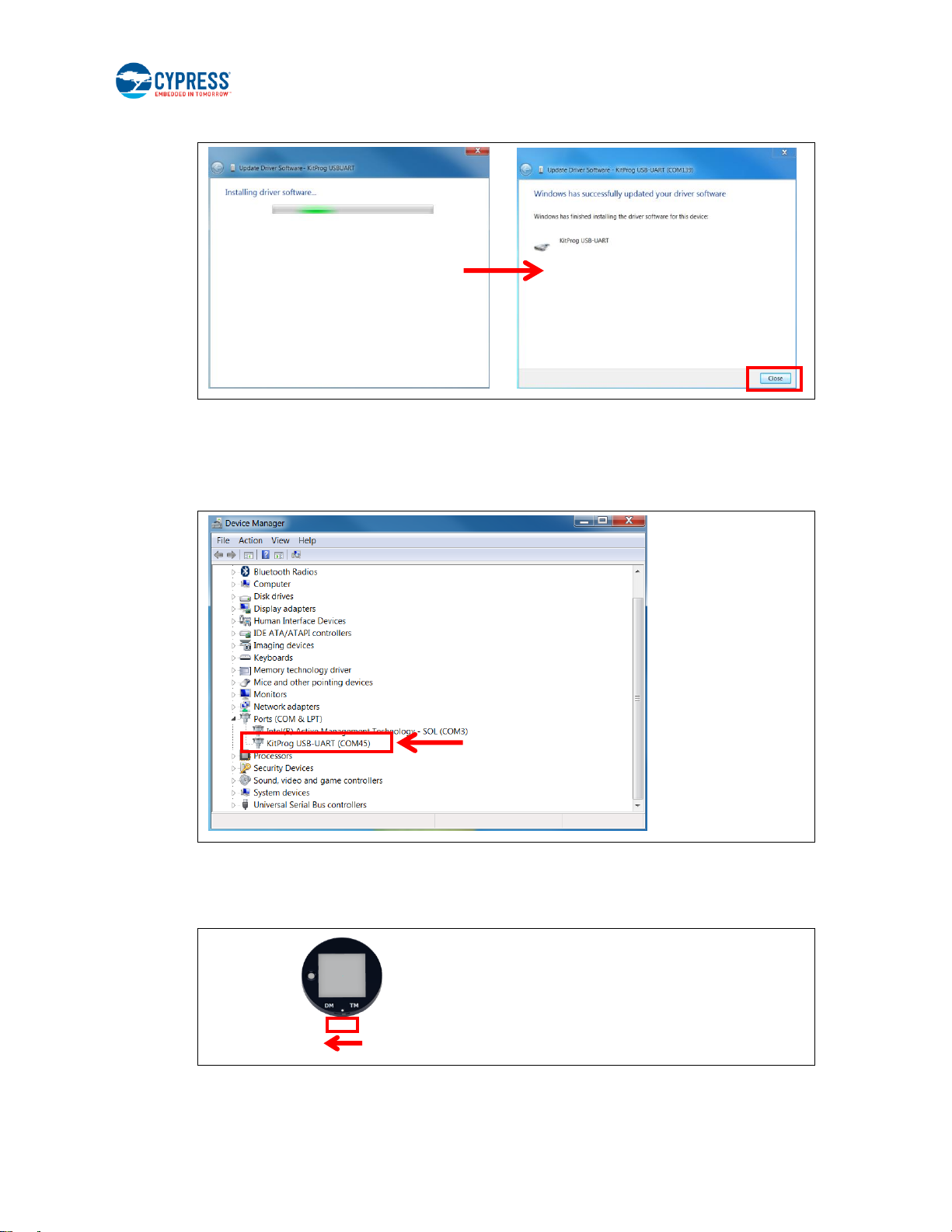
6. Start installing the USB driver. Click the Close button when the KitProg USB-UART driver installation finishes.
7. After successful device driver installation, confirm that a new COM port called “KitProg USB-UART” was added:
A. Open the Device Manager.
B. Under Ports (COM & LPT), confirm that a COM port called “KitProg USB-UART” was added.
Note the COM number (COMxx).
3.1.3 Establishing BLE Connection
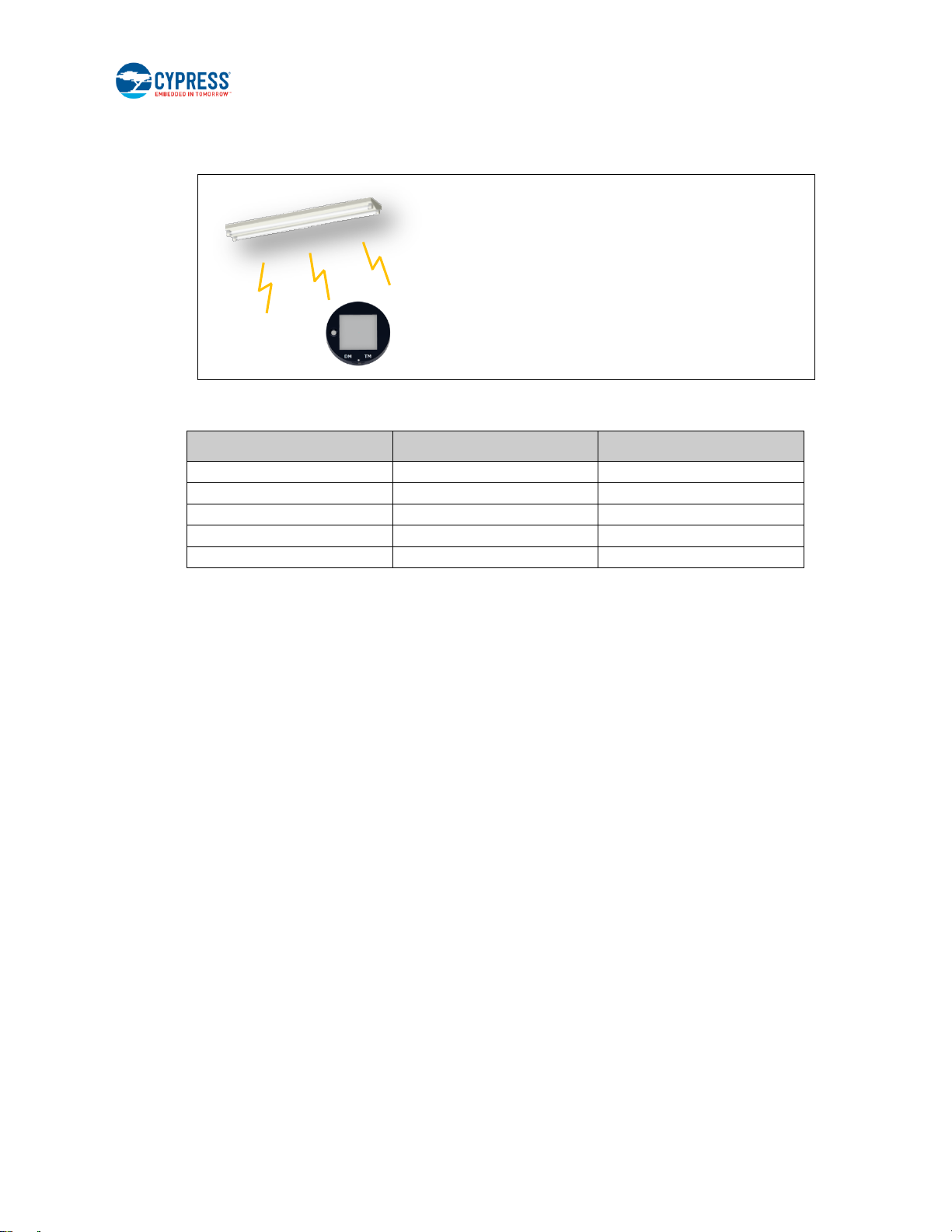
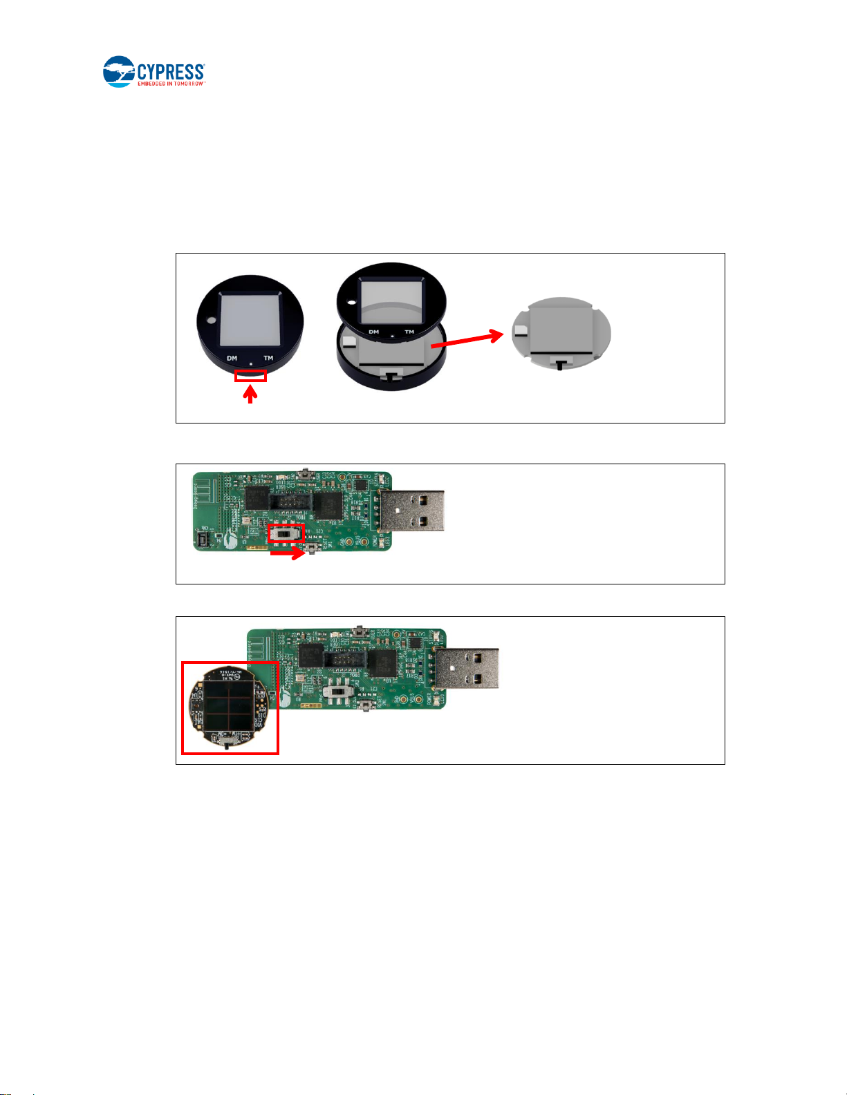
1. Set the slide switch (SW1) on the Solar BLE Sensor to Demo mode (DM). Refer to 5.1.4.1 Waveform of Demo Mode and
Timer Mode for detailed information on each mode.
Note: Use the sharp end of something like tweezers (not included in the kit) to change the mode.
CYALKIT-E02 Solar-Powered BLE Sensor Beacon Reference Design Kit Guide, Doc. No. 002-11317 Rev. *C 19
Page 20
Getting Started
Typical Light Level
Environment
Time Interval of Sensor1
~1 lx
Moonlight
Does not work
100 lx~200 lx
Under street lighting
50 s ~
200 lx~400 lx
At museum
30 s ~ 50 s
400 lx~500 lx
Office lighting
15 s ~ 30 s
1000 lx ~
Shopping mall, rainy day
3 s ~ 15 s
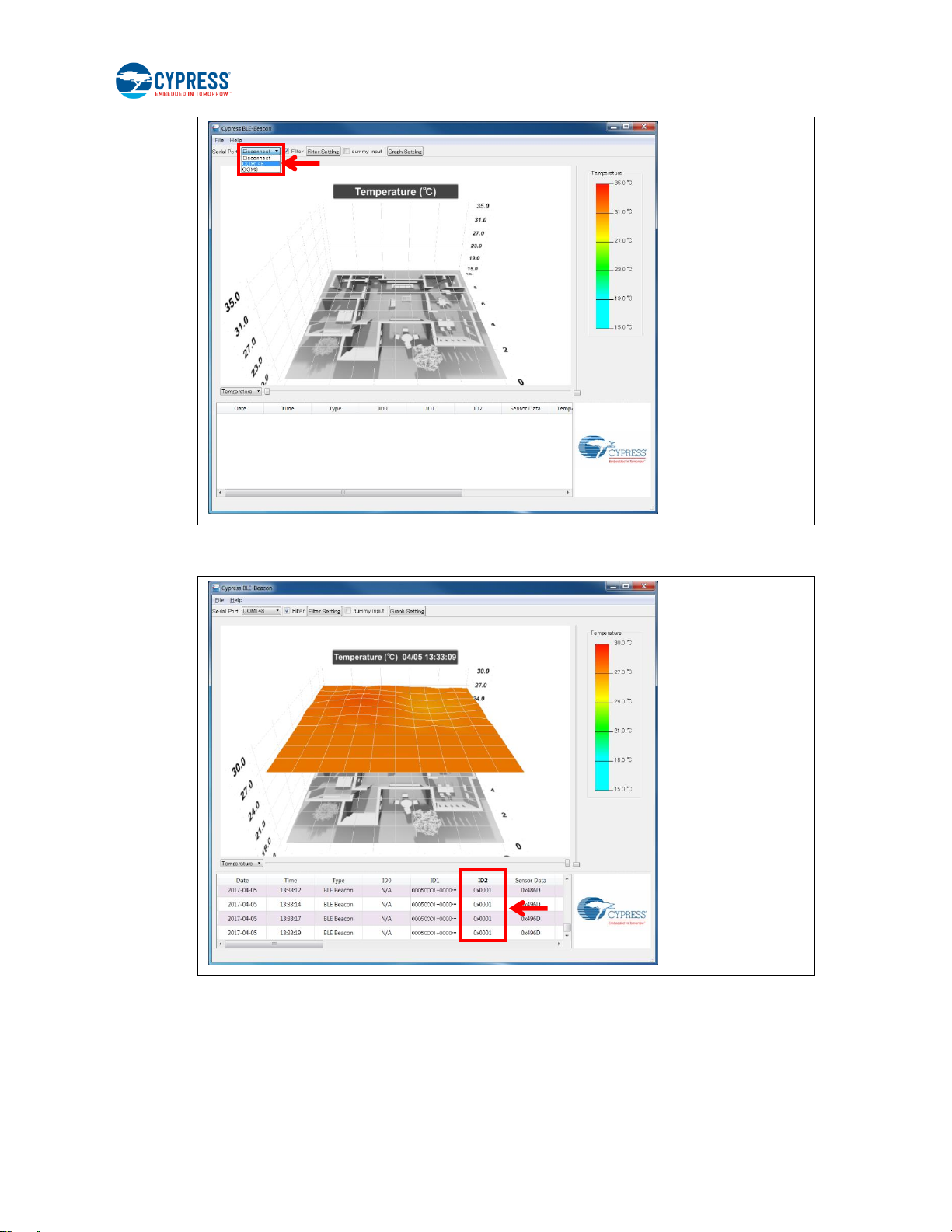
2. Place the Solar BLE Sensor under an office light. The firmware to operate the Solar BLE Sensor as a BLE sensor
beacon is preloaded from the factory. After placing the Solar BLE Sensor under a suitable light (refer to Table 3-1. Light
Level Versus Time Interval), it will automatically power up and begin transmitting.
Table 3-1. Light Level Versus Time Interval
1
The time interval of the sensor is three seconds in all light levels when the supercapacitor on the Solar BLE Sensor is fully charged.
3. Plug the Debug Board into your computer’s USB port.
4. Run CypressBLE-Beacon.exe, which is in the Windows application used to view the data received from the Solar BLE
Sensor. It is located in the Software folder that you installed earlier:
<Install directory>\Cypress BLE-Beacon\EXE
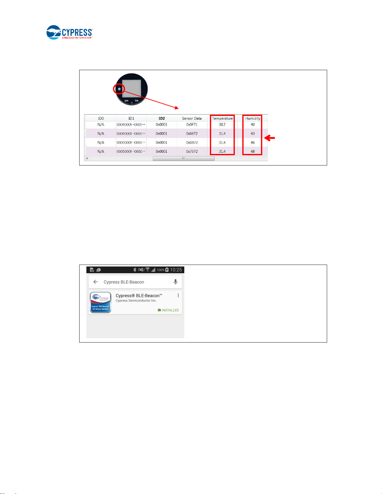
A Cypress BLE-Beacon window will appear. Select COMxx in the Serial Port drop-down menu, where COMxx
corresponds to the port that was confirmed in step 5 of 3.1.1 USB Driver Installation of Debug Board.
CYALKIT-E02 Solar-Powered BLE Sensor Beacon Reference Design Kit Guide, Doc. No. 002-11317 Rev. *C 20
Page 21
Getting Started
5. Find the ID2 number (initial value is 0x0001) of the Solar BLE Sensor in the Cypress BLE-Beacon software. Refer to 3.3
Configuring Solar BLE Sensor to change the ID2 number.
CYALKIT-E02 Solar-Powered BLE Sensor Beacon Reference Design Kit Guide, Doc. No. 002-11317 Rev. *C 21
Page 22
Getting Started
Touch the
sensor
6. Confirm that the WSN is operating by placing your finger on the sensor on the Solar BLE Sensor. Placing your finger
raises the temperature and humidity from the indoor environment condition. You should see a corresponding change in
temperature or humidity on your PC. When touching the board, be careful of static electricity.
Refer to Cypress BLE-Beacon PC User Guide for detailed information.
3.2 WSN Operation with Mobile Device
In this section, you will confirm that the Solar BLE Sensor is operating as a WSN by using the apps on your mobile device to
detect temperature and humidity changes.
3.2.1 Mobile Apps Installation
The Cypress BLE-Beacon app is available on Google Play and in the Apple Store for free. To install the app, follow these
instructions.
3.2.1.1 Installing the Android App
1. Open Google Play and search for “Cypress BLE-Beacon”.
2. Select the Cypress BLE-Beacon (BLE-Beacon) app. On the subsequent screen, click the Install button to proceed with
installation.
3. When presented with the app permission dialog, click Accept to continue.
4. When the installation is complete, the BLE-Beacon app can be launched from the App Drawer.
5. Place the Solar BLE Sensor under an office light. Refer to step 2 of 3.1.3 Establishing BLE Connection.
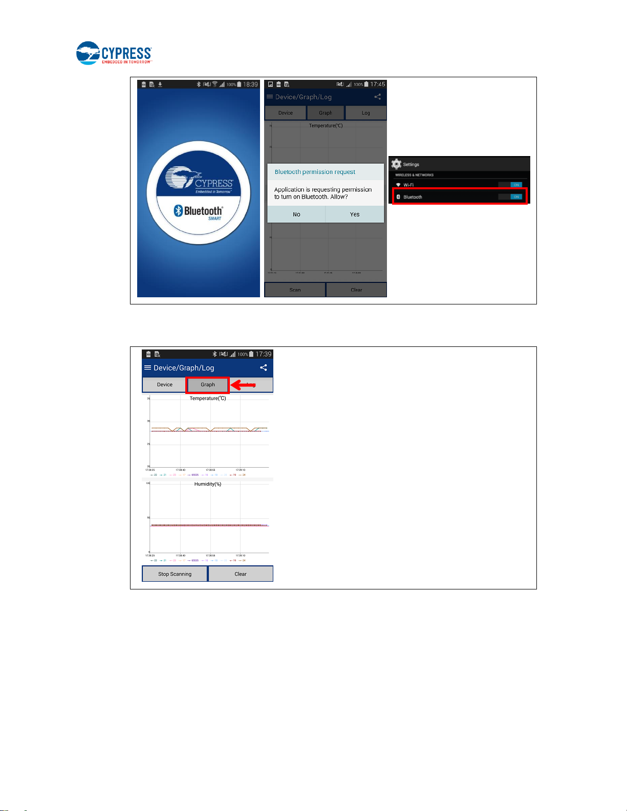
6. Launch the BLE-Beacon app. A splash screen is displayed for a few seconds before the app displays the Device List
screen. If Bluetooth is turned OFF in the Android device, Android OS will prompt you to turn ON Bluetooth.
CYALKIT-E02 Solar-Powered BLE Sensor Beacon Reference Design Kit Guide, Doc. No. 002-11317 Rev. *C 22
Page 23
Getting Started
7. The BLE-Beacon app performs device discovery by default when the app is opened. Select the mode as Graph to
display the sensor data.
Refer to Cypress BLE-Beacon Android App User Guide for detailed information.
CYALKIT-E02 Solar-Powered BLE Sensor Beacon Reference Design Kit Guide, Doc. No. 002-11317 Rev. *C 23
Page 24
Getting Started
3.2.1.2 Installing the iOS App
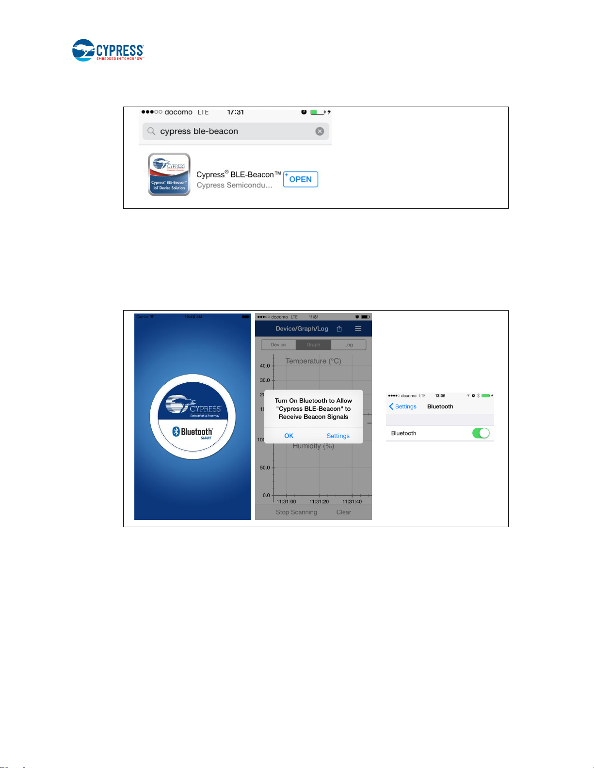
1. Open the App Store and search for “Cypress BLE-Beacon.”
2. Select the Cypress BLE-Beacon (BLE-Beacon) app, and proceed to install the app on your iOS device.
3. Place the Solar BLE Sensor under an office light. Refer to step 2 of 3.1.3 Establishing BLE Connection.
4. Launch the BLE-Beacon app. A splash screen is displayed for a few seconds before the app displays the Device List
screen. If Bluetooth is turned OFF in the iOS device, iOS will display a message box to turn ON Bluetooth with the
Settings and OK buttons. Click the Settings button to turn ON Bluetooth on the Settings screen. Clicking the OK
button will display the message “Please turn Bluetooth ON,” which requires the standard iOS procedure to turn ON
Bluetooth.
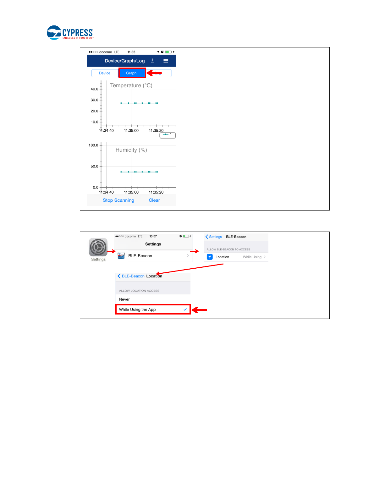
5. The BLE-Beacon app performs device discovery by default when the app is opened. Select the mode as Graph to
display the sensor data.
CYALKIT-E02 Solar-Powered BLE Sensor Beacon Reference Design Kit Guide, Doc. No. 002-11317 Rev. *C 24
Page 25
Getting Started
Note that if the sensor data has not appeared on the BLE-Beacon of iOS, you need to confirm that the Location setting
is set to While Using the App (iOS: Home screen > Settings > BLE-Beacon > Location).
Refer to Cypress BLE-Beacon iOS App User Guide for detailed information.
CYALKIT-E02 Solar-Powered BLE Sensor Beacon Reference Design Kit Guide, Doc. No. 002-11317 Rev. *C 25
Page 26
Getting Started
SW3
PRoC BLE
EZ-BLE
3.3 Configuring Solar BLE Sensor
In this section, you will configure a parameter of the Solar BLE Sensor according to preprogrammed firmware for this kit. You
will do so using a serial USB connection from your PC to send configuration commands to the Solar BLE Sensor.
3.3.1 Connect Solar BLE Sensor to PC
1. Open the enclosure of Solar BLE Sensor using the sharp end of something like tweezers (not included in the kit), and
take out the Solar BLE Sensor Board. Refer to B.2 How to Install the Board in the Enclosure for how to install the board
in the enclosure.
2. Set the slide switch (SW3) on the Debug Board to the EZ-BLE side. Refer to section Slide Switch for Target Device
Select for detailed information on each mode.
3. Connect the Solar BLE Sensor to CN1 of the Debug Board.
4. Plug the Debug Board with the Solar BLE Sensor into your computer’s USB port. A supercapacitor (SC1) on the Solar
BLE Sensor is charged when the Solar BLE Sensor is connected to the Debug Board via USB. Refer to Charging the
Supercapacitor for detailed information.
CYALKIT-E02 Solar-Powered BLE Sensor Beacon Reference Design Kit Guide, Doc. No. 002-11317 Rev. *C 26
Page 27
Getting Started
3.3.2 Configuring Solar BLE Sensor
1. Confirm that a COM port (KitProg USB-UART) was added in the Device Manager (refer to step 5 of 3.1.1 USB Driver
Installation of Debug Board for detailed information):
Open the Device Manager.
Under Ports (COM & LPT), confirm that a KitProg USB-UART was added. Note the COM number (COMxxx).
2. Install Tera Term from the following location:
<Install directory>\Cypress BLE-Beacon\teraterm
3. After it is installed, run Tera Term:
□ Windows 7: Start > All Programs > Tera Term
□ Windows 8/8.1: [Ctrl] [Tab] > All Apps > Tera Term
□ Windows 10: Start button > All Apps > Tera Term
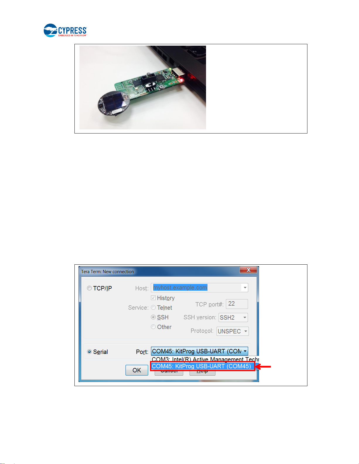
4. In Tera Term, select File > New Connection. On the New Connecction window, click Serial and select “COMxxx:
KitProg USB-UART (COMxxx).” Then click OK.
CYALKIT-E02 Solar-Powered BLE Sensor Beacon Reference Design Kit Guide, Doc. No. 002-11317 Rev. *C 27
Page 28

Getting Started
5. Configure the terminal setting (Setup > Terminal) as follows. Then click OK.
□ Receive: AUTO
□ Transmit: CR+LF
□ Local echo: Select
□ Other settings: Default
6. Configure the serial port setting (Setup > Serial Port) as follows. Then click OK.
□ Baud rate: 115200
□ Other settings: Default
CYALKIT-E02 Solar-Powered BLE Sensor Beacon Reference Design Kit Guide, Doc. No. 002-11317 Rev. *C 28
Page 29

Getting Started
SW1
Push
7. Push and release the RESET button (SW1) on the Debug Board. Note that when the Solar BLE Sensor is in this mode, it
stops transmitting BLE sensor data.
8. Confirm that the Solar BLE Sensor is in the command mode by observing that the “Start…” message appears on Tera
Term. Your board is ready to receive commands.
9. For example, this step will set the Major ID to “0x000a” (Hexadecimal) to receive another Solar BLE Sensor ID. On Tera
Term, type major 000A. The Solar BLE Sensor responds with a confirmation message as follows. Refer to section 3.4
Serial Command List for a list of all kit commands.
10. To confirm the operation of the changed parameter when using USB bus power, type exit. The board will acknowledge
the command by responding with “exit.”
If you do not need to confirm the operation when using USB bus power, skip this step and the next one (step11).
CYALKIT-E02 Solar-Powered BLE Sensor Beacon Reference Design Kit Guide, Doc. No. 002-11317 Rev. *C 29
Page 30

Getting Started
PRoC BLE
EZ-BLE
SW3
11. You can recognize the changed MAJOR value 10 (Decimal) on apps when using USB bus power (initial time interval is
1.5 s when using USB bus power).
12. Disconnect the Debug Board from the PC and then disconnect the Solar BLE Sensor from the Debug Board. Set the
slide switch (SW3) on the Debug Board to the PRoC BLE side to receive the sensor data.
13. Plug the Debug Board into your computer’s USB port again.
CYALKIT-E02 Solar-Powered BLE Sensor Beacon Reference Design Kit Guide, Doc. No. 002-11317 Rev. *C 30
Page 31

Getting Started
No.
Command
Name
Command
Use
Description
Default
[1]
UUID
For BLE
Beacon Mode
Read/Write of UUID1
00050001-0000-1000-8000-00805F9B0131 [hex]
[2]
MAJOR
Read/Write of MAJOR1
0x0001
[3]
TXPWR
Read/Write the Transmitter Power
Strength in BLE Beacon mode
3 dBm
[4]
RSSI
Read/Write of Received Power
Strength for distance 1m (RSSI)
-61 dBm
[5]
COID
Read/Write of Bluetooth Company
0x004C
[6]
EDNID
For Eddystone
Mode
Read/Write NID
CB6F15CEC02A41F76AB1 [hex]
[7]
EDBID
Read/Write BID
000000010001 [hex]
[8]
EDTXPWR
Read/Write the Transmitter Power
Levels in Eddystone mode
-18 -12 0 3 dBm
[9]
EDFRAME
Read/Write Eddystone Frame
Advertisement Flags
uid on, url off, tlm on
[10]
EDSTATE
Read the Lock State
Unlocked
[11]
EDLOCK
Lock Eddystone-URL Configuration
Service and set the lock-code
00000000-0000-0000-0000-000000000000 [hex]
[12]
EDUNLOCK
Unlock Eddystone-URL Configuration
Service
-
[13]
EDURI
Read/Write the URL
http://www.cypress.com/
PC
Apps
14. Confirm the changed MAJOR value 0x000A via PC (Refer to 3.1 WSN Operation with PC) or apps (Refer to 3.2 WSN
Operation with Mobile Device) by energy harvesting operation.
Refer to Table 3-1 for the time interval of the energy harvesting operation.
3.4 Serial Command List
Table 3-2 lists the serial commands that can be used to control the kit from your computer using the USB serial interface.
Refer to the 3.3 Configuring Solar BLE Sensor section for instructions on how to issue these commands via the USB serial
interface. The commands are not case-sensitive.
Note that the following commands are for CYALKIT-E02 Sample Firmware, Version 1.2.00. Refer to 4.2 Programming and
Debugging section for instructions on how to program the firmware.
Table 3-2. Command List
CYALKIT-E02 Solar-Powered BLE Sensor Beacon Reference Design Kit Guide, Doc. No. 002-11317 Rev. *C 31
Page 32

Getting Started
No.
Command
Name
Command
Use
Description
Default
[14]
EDADPWR
Read/Write the Received Power
Levels at 0 meters(RSSI)
-41 -35 -23 -20 dBm
[15]
EDTXMODE
Read/Write TX Power Mode
HIGH
[16]
EDITRVL
Read/Write the Advertise Interval in
Eddystone mode
100 ms
(Note: when this value is 0, and MODE is Eddystone,
there’s no advertisement.)
[17]
EDRESET
Set Eddystone parameters to their
initial values except EDNID, EDBID
and EDFRAME.
[18]
MODE
For Both
Modes
Read/Write mode
BLE Beacon
[19]
INIT
Default all parameters
-
[20]
EXIT
Exit the UART command waiting mode
and Eddystone-URL Configuration
Service, then start BLE advertisements
[21]
VER
Display Firmware Version
-
[22]
HELP
Display Command List
-
1
Refer to BLE Beacon Format for detailed information.
[1] Read/Write of UUID
[1-1] Read
Read UUID data. Default: 00050001-0000-1000-8000-00805F9B0131
<Example>
UUID⏎
(echo) UUID
(output) -> UUID: 00050001-0000-1000-8000-00805F9B0131
[1-2] Write
Write UUID data.
<Example>
UUID EEEEDDDD-CCCC-BBBB-AAAA-999988887777⏎
(echo) UUID EEEEDDDD-CCCC-BBBB-AAAA-999988887777
(output) -> New UUID: EEEEDDDD-CCCC-BBBB-AAAA-999988887777
[2] Read/Write of MAJOR
[2-1] Read
Read MAJOR. Default: 0x0001
<Example>
MAJOR⏎
(echo) MAJOR
(output) -> MAJOR: 0001
CYALKIT-E02 Solar-Powered BLE Sensor Beacon Reference Design Kit Guide, Doc. No. 002-11317 Rev. *C 32
Page 33

Getting Started
[2-2] Write
Write MAJOR.
<Example>
MAJOR 1A2F⏎ <- Input HEX data
(echo) MAJOR 1A2F
(output) -> New MAJOR: 1A2F
[3] Read/Write of Transmitter Power Strength
[3-1] Read
Read Power Strength. Default: 3 dBm
<Example>
TXPWR⏎
(echo) TXPWR
(output) -> TX power in dBm: 3
[3-2] Write
Set Power Strength. Set Value: -18, -12, -6, -3, -2, -1, 0, 3
<Example>
TXPWR -18⏎
(echo) TXPWR -18
(output) -> New TX power in dBm: -18
[4] Read/Write of Receiver Power Strength for distance 1m (RSSI)
[4-1] Read
Read RSSI. Default: -61dBm
<Example>
RSSI⏎
(echo) RSSI
(output) -> RSSI in dBm: -61
[4-2] Write
Set RSSI.
<Example>
RSSI -90⏎
(echo) RSSI -90
(output) -> New RSSI in dBm: -90
[5] Read/Write of Bluetooth Company
[5-1] Read
CYALKIT-E02 Solar-Powered BLE Sensor Beacon Reference Design Kit Guide, Doc. No. 002-11317 Rev. *C 33
Page 34

Getting Started
Read Bluetooth Company. Default: 0x004C
<Example>
COID⏎
(echo) COID
(output) -> Company ID: 004C
[5-2] Write
Write Bluetooth Company.
<Example>
COID 0059⏎ <- Input HEX data
(echo) COID 0059
(output) -> New Company ID: 0059
[6] Read/Write NID
[6-1] Read
Read NID data. Default: CB6F15CEC02A41F76AB1
<Example>
EDNID⏎
(echo) EDNID
(output) -> Eddystone-UID NID : CB6F15CEC02A41F76AB1
[6-2] Write
Write NID data.
<Example>
EDNID 00010203040506070809⏎ <- Input HEX data
(echo) EDNID 00010203040506070809
(output) -> New Eddystone-UID NID : 00010203040506070809
[7] Read/Write BID
[7-1] Read
Read BID data. Default: 000000010001
<Example>
EDBID⏎
(echo) EDBID
(output) -> Eddystone-UID BID : 000000010001
[7-2] Write
Write BID data
<Example>
CYALKIT-E02 Solar-Powered BLE Sensor Beacon Reference Design Kit Guide, Doc. No. 002-11317 Rev. *C 34
Page 35

Getting Started
EDBID 0A0B0C0D0E0F⏎ <- Input HEX data
(echo) EDBID 0A0B0C0D0E0F
(output) -> New Eddystone-UID BID : 0A0B0C0D0E0F
[8] Read/Write the Transmitter Power Levels in Eddystone mode
[8-1] Read
Read Power Strength levels. Default: -18 -12 0 3 dBm
The four Levels correspond to TX_POWER_MODE_LOWEST, TX_POWER_MODE_LOW,
TX_POWER_MODE_MEDIUM, TX_POWER_MODE_HIGH.
<Example>
EDTXPWR⏎
(echo) EDTXPWR
(output) -> Eddystone Radio TX Power Levels : -18 -12 0 3
[8-2] Write
Set Power Strength levels. Set Value: -18, -12, -6, -3, -2, -1, 0, 3
Writing is not allowed if Eddystone-URL Configuration Service is locked. The four Levels
correspond to TX_POWER_MODE_LOWEST, TX_POWER_MODE_LOW,
TX_POWER_MODE_MEDIUM, TX_POWER_MODE_HIGH.
<Example>
EDTXPWR -6 -3 -2 -1⏎
(echo) EDTXPWR -6 -3 -2 -1
(output) -> New Eddystone Radio TX Power Levels : -6 -3 -2 -1
[9] Read/Write Eddystone Frame Advertisement Flags
[9-1] Read
Read Frame Flags. Default: uid on, url off, tlm on
<Example>
EDFRAME⏎
(echo) EDFRAME
(output) -> EDFrame mode : uid on, url off, tlm on
[9-2] Write
Set Frame Flags.
<Example>
EDFRAME uid url⏎ Set Value: uid, url, tlm
(echo) EDFRAME uid url
(output) -> New EDFrame mode : uid on, url on, tlm off
CYALKIT-E02 Solar-Powered BLE Sensor Beacon Reference Design Kit Guide, Doc. No. 002-11317 Rev. *C 35
Page 36

Getting Started
[10] Read the Lock State
Read the lock state. Default: unlocked
<Example>
EDSTATE⏎
(echo) EDSTATE
(output) -> EDSTATE: unlocked
[11] Lock Eddystone-URL Configuration Service and set the lock-code
Write new lock-code and lock Eddystone-URL Configuration Service. This write operation is not
allowed if Eddystone-URL Configuration Service is locked.
<Example>
EDLOCK EEEEDDDD-CCCC-BBBB-AAAA-999988887777⏎
(echo) EDLOCK EEEEDDDD-CCCC-BBBB-AAAA-999988887777
(output) -> New EDSTATE: locked
[12] Unlock Eddystone-URL Configuration Service
Unlock Eddystone-URL Configuration Service with lock-code set by EDLOCK command. If user
forgets the code, user needs send the DEFAULT command to change the lock state to unlocked.
<Example>
EDUNLOCK EEEEDDDD-CCCC-BBBB-AAAA-999988887777⏎
(echo) EDUNLOCK EEEEDDDD-CCCC-BBBB-AAAA-999988887777
(output) -> New EDSTATE: unlocked
[13] Read/Write the URL
[13-1] Read
Read the URL. Default: http://www.cypress.com/
<Example>
EDURI⏎
(echo) EDURI
(output) -> Eddystone-URL URI Data: http://www.cypress.com/
[13-2] Write
Write the URL. This write operation is not allowed if Eddystone-URL Configuration Service is
locked.
The length is limited. The URL is case-sensitive except the protocol (http or https) and the domain.
<Example 1>
EDURI http://www.Abc.com/Root⏎ <- Input [protocol]://[domain]/[path]
(echo) EDURI http://www.Abc.com/Root
(output) -> New Eddystone-URL URI Data : http://www.abc.com/Root
<Example 2>
CYALKIT-E02 Solar-Powered BLE Sensor Beacon Reference Design Kit Guide, Doc. No. 002-11317 Rev. *C 36
Page 37

Getting Started
EDURI 0061626307⏎ <- Input HEX data
(echo) EDURI 0061626307
(output) -> New Eddystone-URL URI Data : 0061626307
[14] Read/Write the Received Power Levels at 0 meters(RSSI)
[14-1] Read
Read RSSI Levels. Default: -41 -35 -23 -20 dBm
The four levels correspond to TX_POWER_MODE_LOWEST, TX_POWER_MODE_LOW,
TX_POWER_MODE_MEDIUM, TX_POWER_MODE_HIGH.
<Example>
EDADPWR⏎
(echo) EDADPWR
(output) -> Eddystone Advertised TX Power Levels : -41 -35 -23 -20
[14-2] Write
Set RSSI Levels. Set Value: -100~20 dBm
This operation is not allowed if Eddystone-URL Configuration Service is locked. The four levels
correspond to TX_POWER_MODE_LOWEST, TX_POWER_MODE_LOW,
TX_POWER_MODE_MEDIUM, TX_POWER_MODE_HIGH.
<Example>
EDADPWR -100 -50 0 20⏎
(echo) EDADPWR -100 -50 0 20
(output) -> New Eddystone Advertised TX Power Levels : -100 -50 0 20
[15] Read/Write TX Power Mode
[15-1] Read
Read TX Power Mode. Default: HIGH
<Example>
EDTXMODE⏎
(echo) EDTXMODE
(output) -> Eddystone TX Power Mode : HIGH
[15-2] Write
Set TX Power Mode. Set Value: LOWEST, LOW, MEDIUM, HIGH
This write operation is not allowed if Eddystone-URL Configuration Service is locked.
<Example>
EDTXMODE LOW⏎
(echo) EDTXMODE LOW
(output) -> New Eddystone TX Power Mode : LOW
CYALKIT-E02 Solar-Powered BLE Sensor Beacon Reference Design Kit Guide, Doc. No. 002-11317 Rev. *C 37
Page 38

Getting Started
[16] Read/Write the Advertise Interval in Eddystone mode
[16-1] Read
Read Advertise Interval. Default: 1000ms
<Example>
EDITRVL⏎
(echo) EDITRVL
(output) -> Eddystone advertise Interval in msec: 1000
[16-2] Write
Set Advertise Interval. Set Value: 0, 100~10240 ms
This operation is not allowed if Eddystone-URL Configuration Service is locked.
<Example>
EDITRVL 10240⏎
(echo) EDITRVL 10240
(output) -> New Eddystone Advertise Interval in msec: 10240
[17] EDRESET
Set Eddystone parameters to their initial values except EDNID, EDBID and EDFRAME.
This operation is not allowed if Eddystone-URL Configuration Service is locked.
<Example>
EDRESET ⏎
(echo) EDRESET
(output) -> Reset finished!
[18] Read/Write the mode
[18-1] Read
Read the mode setting Default: BLEBeacon
<Example>
MODE⏎
(echo) MODE
(output) -> Mode : BLEBeacon
[18-2] Write
Change the mode setting set value: BLEBeacon, Eddystone, EDTest
<Example>
MODE Eddystone⏎
(echo) MODE Eddystone
(output) -> New mode : Eddystone
CYALKIT-E02 Solar-Powered BLE Sensor Beacon Reference Design Kit Guide, Doc. No. 002-11317 Rev. *C 38
Page 39

Getting Started
[19] INIT
Change all the settings to their default values.
<Example>
INIT⏎
(echo) INIT
(output) -> Restore to default!
[20] EXIT
Exit the UART command waiting mode and Eddystone-URL Configuration Service, then start
BLE advertisements.
<Example>
EXIT⏎
(echo) EXIT
(output)
[21] VER
Display Firmware Version.
<Example>
VER⏎
(echo) VER
(output) -> CYALKIT-E02 Sample Firmware, Version 1.2.00
[22] HELP
Display Command List.
<Example>
HELP⏎
(echo) HELP
(output) Get uuid, input:uuid+Enter
(output) Set uuid, input:uuid xxxxxxxx-xxxx-xxxx-xxxx-xxxxxxxxxxxx+Enter
(output) Get major, input:major+Enter
(output) Set major, input:major xxxx+Enter
(output) Get minor, input:minor+Enter
(output) Set minor, input:minor xxxx+Enter
[*] Input another command (Error Handling)
TEST
(echo) TEST
(output) Command format error!!
CYALKIT-E02 Solar-Powered BLE Sensor Beacon Reference Design Kit Guide, Doc. No. 002-11317 Rev. *C 39
Page 40

Getting Started
No.
Characteristic
Name
Description
Default
[1]
Lock State
Reads the lock state
Functions in the same way as the EDSTATE
command
false(unlocked)
[2]
Lock
Locks the beacon and sets the single-use
lock-code
Functions in the same way as the EDLOCK
command
00000000-00000-0000-0000-000000000000 [hex]
[3]
Unlock
Unlocks the beacon and clears the single-use
lock-code
Functions in the same way as the EDUNLOCK
command
[4]
URI Data
Reads/writes the URL
Functions in the same way as the EDURI
command
http://www.cypress.com/
[5]
URI Flags
Reads/writes the flags
0
[6]
Advertised Tx
Power Levels
Reads/writes the Advertised Power Levels array
Functions in the same way as the EDADPWR
command
-41 -35 -23 -20 dBm
[7]
Tx Power
Mode
Reads/writes the TX Power Mode
Functions in the same way as the EDTXMODE
command
1 [TX_POWER_MODE_HIGH]
[8]
Beacon Period
The period in milliseconds that Eddystone packets
are transmitted
Functions in the same way as the EDITRVL
command
1000 ms
(Note: when this value is 0, and MODE is Eddystone,
there’s no advertisement.)
[8]
Reset
Sets EDTXPWR and all characteristics to their
initial values
Functions in the same way as the EDRESET
command
-
3.5 Eddystone-URL Configuration Service
When the beacon is powered up by USB, it is placed in Configuration Mode after the UART Bootloader boots up the program.
The beacon advertises an ADV packet indicating that mode for 60 seconds. A BLE device can connect to it as a GATT client
before it stops advertising. The client can read or write the Eddystone-URL Configuration Service Characteristics. The
following is the list of the Characteristics. These Characteristics fully comply with descriptions at the following web page:
https://github.com/google/eddystone/blob/master/eddystone-url/docs/config-service-spec.md.
Table 3-3. Characteristic List
3.6 Note About Validators
Google offers two Android apps, eddystone-validator and eddystone-url-config-validator, to assist developers and
implementers in working with Eddystone devices. On some occasions, the eddystone-url-config-validator reports errors
when validating the beacon with it. This section introduces the cause of the errors and the steps to pass the validation.
Eddystone-url-config-validator validates the Eddystone-URL frame. It takes the Eddystone-UID frame and Eddystone-TLM
frame as invalid advertisement packets. It detects Eddystone-UID frame packets immediately after disconnecting itself and
the detection time is limited. Therefore, you must change some settings to have the beacon advertise Eddystone-TLM frame
only, and send the EXIT command through UART immediately after the validator finishes disconnection.
CYALKIT-E02 Solar-Powered BLE Sensor Beacon Reference Design Kit Guide, Doc. No. 002-11317 Rev. *C 40
Page 41

Getting Started
To facilitate Core Eddystone-URL Tests with eddystone-url-config-validator, a new mode is provided to replace these
operations. Ensure that you have set the mode as EDTest before starting the tests.
If testing a write characteristic operation fails, try closing all the Bluetooth apps, powering OFF the Android device, and then
restarting it.
Core Eddystone-URL Tests are completed.
CYALKIT-E02 Solar-Powered BLE Sensor Beacon Reference Design Kit Guide, Doc. No. 002-11317 Rev. *C 41
Page 42

4. Program and Debug
SW3
PRoC BLE
EZ-BLE
The Solar-Powered BLE Sensor Beacon RDK can be programmed and debugged using KitProg (PSoC 5LP) on the Debug
Board. Before debugging the device, ensure that PSoC Creator is installed on the computer.
4.1 KitProg
KitProg is the hardware/firmware block for onboard programming, debugging, and bridge functionality. It is a common
reusable hardware/firmware block used across many Cypress kit platforms. It consists of a PSoC 5LP device, which connects
to the computer over a USB interface and connects to PRoC BLE on the Debug Board or EZ-BLE module on the Solar BLE
Sensor over SWD, I2C, and UART pins. KitProg communicates with PSoC Programmer and PSoC Creator software to
program/debug the target PRoC BLE or EZ-BLE module over the SWD interface. The main advantage of an onboard
programmer/debugger is that users do not have to buy extra programmer/debugger hardware.
4.2 Programming and Debugging
4.2.1 Initial setup
4.2.1.1 Solar BLE Sensor
To program and debug the EZ-BLE module on the Solar BLE Sensor, set the slide switch (SW3) on the Debug Board to the
EZ-BLE side. Then connect the Solar BLE Sensor to CN1 of the Debug Board.
4.2.1.2 Debug Board
To program and debug the PRoC BLE on the Debug Board, set the slide switch (SW3) on the Debug Board to the PRoC BLE
side. Do not connect the Solar BLE Sensor to CN1.
CYALKIT-E02 Solar-Powered BLE Sensor Beacon Reference Design Kit Guide, Doc. No. 002-11317 Rev. *C 42
Page 43

Program and Debug
PRoC BLE
EZ-BLE
SW3
4.2.2 Programming and Debugging Using PSoC Creator
1. Plug the Debug Board into your computer’s USB port.
2. If you installed the RDK software to the default location, copy the BLE folder to your local folder. Note that the following
warning message appears when the folder is in C:\Program Files or C:\Program Files (x86).
The BLE folder is located in the Firmware folder that you installed earlier:
<Install directory>\CYALKIT-E02 Solar-Powered BLE Sensor Beacon RDK\<version>\Firmware
8. Open Solar_BLE_Sensor.cywrk or Debug_Board.cywrk for the example project.
9. Clean and build the project by choosing Build > Clean and Build <Project Name>.
CYALKIT-E02 Solar-Powered BLE Sensor Beacon Reference Design Kit Guide, Doc. No. 002-11317 Rev. *C 43
Page 44

Program and Debug
3. If there are no errors during build, program the firmware by clicking the Program button on the toolbar or pressing [Ctrl]
[F5], as follows. This will program EZ-BLE or PRoC BLE so it will be ready for use.
4. To debug the device, click the Debug icon or press [F5], as follows.
5. When PSoC Creator opens in debug mode, use the buttons on the toolbar for debugging. For more details on using the
debug features, see the Cypress application note AN96841 – Getting Started with EZ-BLE Module or AN94020 –
Getting Started with PRoC BLE.
4.2.3 Programming Using PSoC Programmer
PSoC Programmer (3.24 or later) can be used to program existing hex files into both PSoC BLE and the EZ-BLE module. To
do so, follow these steps.
1. Refer to 4.2.1 Initial setup to select the target device.
2. Plug the Debug Board into your computer’s USB port and open PSoC Programmer from Start > All Programs >
Cypress > PSoC Programmer <version> > PSoC Programmer <version>.
3. Select “KitProg/BLE*******” in Port Selection, and then click the File Load button at the top left corner of the window.
Browse for the desired hex file and click Open. The example hex files are located in the Hex Files folder.
<Install directory>\CYALKIT-E02 Solar-Powered BLE Sensor Beacon RDK\<version>\Firmware\BLE\Hex Files
CYALKIT-E02 Solar-Powered BLE Sensor Beacon Reference Design Kit Guide, Doc. No. 002-11317 Rev. *C 44
Page 45

Program and Debug
CYALKIT-E02 Solar-Powered BLE Sensor Beacon Reference Design Kit Guide, Doc. No. 002-11317 Rev. *C 45
Page 46

Program and Debug
4. Click the Program button to start programming the kit with the selected file.
Note: If the hex file does not match the device selected, then PSoC Programmer will throw an error of device mismatch and
terminate programming.
5. When programming is finished successfully, indicated by a PASS message on the status bar, the Solar BLE Sensor or
Debug Board is ready for use. Close PSoC Programmer.
CYALKIT-E02 Solar-Powered BLE Sensor Beacon Reference Design Kit Guide, Doc. No. 002-11317 Rev. *C 46
Page 47

Program and Debug
4.3 Updating KitProg Firmware
The KitProg firmware normally does not require any updating. If an update is required, then PSoC Programmer will display a
warning message when the kit is connected to it, as follows.
To update KitProg, go to the Utilities tab in PSoC Programmer and click Upgrade Firmware, as follows.
CYALKIT-E02 Solar-Powered BLE Sensor Beacon Reference Design Kit Guide, Doc. No. 002-11317 Rev. *C 47
Page 48

5. Reference Design
Demo Mode
(DM)
Timer Mode
(TM)
SW1
This chapter introduces you to the Solar BLE Sensor hardware and firmware initially provided. It discusses features such as
the WSN with the BLE Beacon process.
5.1 Hardware Description
The Solar BLE Sensor has two modes: Demo mode and Timer mode. Refer to section Internal Timer Setting Block for detailed
information. You can set these modes using SW1 on the Solar BLE Sensor. This section details the information for
S6AE103A.
Note: When the Solar BLE Sensor is in the enclosure, use the sharp end of something like tweezers (not included in the kit) to
change the mode.
The following is the circuit of the S6AE103A energy harvesting PMIC. There are four main blocks to operate it. Refer to the
S6AE103A datasheet for detailed specifications. The schematic and board layouts are available at the following location:
<Install directory>\CYALKIT-E02 Solar-Powered BLE Sensor Beacon RDK\<version>\Hardware
1. Power input block
2. VOUT setting block
3. Storage and VOUT control block
4. Internal timer setting block
CYALKIT-E02 Solar-Powered BLE Sensor Beacon Reference Design Kit Guide, Doc. No. 002-11317 Rev. *C 48
Page 49

Reference Design
Pin Name:
Description:
VBAT
Connect TP1
Primary battery input pin
Extra battery input
VDD
Connect the solar cell (AM-1606C)
Solar cell input pin
Diode (D1) for reverse current protection
Capacitor (C1) for charging input energy
ENA_COMP
Connect GND (H: Enable, L: Disable)
Comparator control pin
It is set to disable.
STBY_LDO
Connect GND (H: Normal, L: Standby)
LDO operation mode setting pin
The LDO is not used when ENA_LDO is low.
1 2 3
4
5.1.1 Power Input Block
This section describes the S6AE103A power input block as shown in the following schematic. There are two power inputs for
solar energy (VDD) and primary battery input (VDD) and some control pins for internal LDO, comparator, and interrupt input.
Table 5-1. Pin Description of Power Input Block
CYALKIT-E02 Solar-Powered BLE Sensor Beacon Reference Design Kit Guide, Doc. No. 002-11317 Rev. *C 49
Page 50

Reference Design
Pin Name:
Description:
ENA_LDO
Connect GND (H: Enable, L: Disable)
LDO output control pin
It is set to disable.
INT
Connect VINT
Event-driven mode control pin
VOUT2 is always active.
5.1.1.1 Solar Cell Specification
Refer to section 6.1.1 15 x 15 mm Solar Cell for detailed specifications.
5.1.1.2 Diode Connection Between Solar Cell and VDD
Refer to Diode Connection Between Solar Cell and VDD for detailed information.
5.1.1.3 VBAT Connection (optional)
Refer to Battery Input Operation.
5.1.2 VOUT Setting Block
This section describes the VOUT settings of S6AE103A as shown in the following schematic. The VOUT1 and VOUT2 output
voltage of S6AE103A can be set by changing the resistors connected to the SET_VOUTH and SET_VOUTL pins because the
VOUT upper limit voltage (VVOUTH) and VOUT lower limit voltage (VVOUTL) are set based on the connected resistors. The
SET_VOUTFB pin outputs a reference voltage for setting the VOUT upper limit voltage and VOUT lower limit voltage. The
voltages applied to the SET_VOUTH and SET_VOUTL pins are produced by dividing this reference voltage outside the IC.
The VOUT upper limit voltage (VVOUTH) and VOUT lower limit voltage (VVOUTL) can be calculated using the following
equations:
VOUT upper limit voltage
VOUT lower limit voltage
5.1.2.1 VOUTL Setting Margin
Refer to Equivalent Series Resistance of the Supercapacitor.
CYALKIT-E02 Solar-Powered BLE Sensor Beacon Reference Design Kit Guide, Doc. No. 002-11317 Rev. *C 50
Page 51

Reference Design
Pin Name:
Description:
VOUT1
Connect load
Output voltage pin 1
Supply energy to BLE and sensor
VOUT2
Open
Output voltage pin 2
Not used for this kit
VSTORE1
Connect 400-µF capacitor
Storage output pin 1
For startup storage
VSTORE1
Connect 200-mF capacitor
Storage output pin 2
To charge a surplus energy
VINT
Connect 1.0-µF capacitor
Internal circuit storage output pin
Fixed to connect capacitor
5.1.3 Storage and VOUT Control Block
This section describes the storage and VOUT control block of S6AE103A as shown in the following schematic. There are two
storage pins and two VOUT pins. The solar energy charges both a small capacitor (400 µF) and a large capacitor (200 mF).
Table 5-2. Pin Description of Storage and VOUT Control Block
5.1.3.1 Waveform of Charging and Discharging Operation
The following are the details of the charging operation and waveform.
1. Solar energy is the input.
2. Charging starts VSTORE1.
3. When the VSTORE1 voltage achieves the VOUTH setting voltage (3.24 V), the VOUT1 voltage turns on and charging
starts the surplus energy to VSTORE2.
4. Repeat to charge both VSTORE1 and VSTORE2.
CYALKIT-E02 Solar-Powered BLE Sensor Beacon Reference Design Kit Guide, Doc. No. 002-11317 Rev. *C 51
Page 52

Reference Design
Charging Operation
ON
ON
OFF
VOUT1
START
VSTORE1
400 uF
VSTORE2
200 mF
0V
0V
0V
VOUTH=3.24V
VOUTM=3.08V
(VOUTHx0.95)
CHRGE
CHRGE
CHRGE CHRGE CHRGE CHRGE
CHRGE
CHRGE
CHRGE
CHRGE
Discharging and Recharging Operation
ON
ON
VOUT1
Solar Input is stopped
VSTORE1
400 uF
VSTORE2
200 mF
0V
0V
0V
VOUTH=3.24V
VOUTM=3.08V
(VOUTHx0.95)
CHRGE
VOUTH=3.24V
VOUTL=1.62V
VOUTL=1.62V
Solar Input is started
ON ON
OFF
DISCHARGE
DISCHARGE
DISCHARGE
DISCHARGE
VSTORE1=
VOUTL(1.62V)
CHRGE
CHRGE
VOUT1 is OFF
CHRGE
CHRGE
1 2 3
4
1 2 3 4 5
6
The following are the details of the discharging and recharging operation and waveform.
1. When the VSTORE1 voltage achieves the VOUTH setting voltage (3.24 V), the surplus energy charges to VSTORE2.
2. Solar input is stopped.
3. The voltage decreases slowly due to load current.
4. When the VSTORE1 voltage achieves VOUTL (1.62 V), the VOUT1 turns off.
5. Solar input is started.
6. When the VSTORE1 voltage achieves the VOUTH setting voltage (3.24 V), the VOUT1 voltage turns on and charging
starts the surplus energy to VSTORE2.
CYALKIT-E02 Solar-Powered BLE Sensor Beacon Reference Design Kit Guide, Doc. No. 002-11317 Rev. *C 52
Page 53

Reference Design
Pin Name:
Mode
Description
CIN0 (not used)
–
Connect 220-pF
Timer time 0 (T0) setting pin
T0 = 0.13 sec1
CIN1
–
Connect 3770-pF
Timer time 1 (T1) setting pin
T1 = 2.07 sec1
CIN2
Demo mode
(C9)
Connect 2200-pF capacitor
Timer time 2 (T2) setting pin
T2 = 1.21 sec1
Timer mode
(C12, C13)
Connect 0.57-µF capacitor
Timer time 2 (T2) setting pin
T2 = 310 sec1
5.1.4 Internal Timer Setting Block
This section describes the S6AE103A internal timer setting block as shown in the following. There are three pins (CIN0/1/2) to
control the VOUT pins, as described in Table 5-3.
Table 5-3. Pin Description of Internal Timer Setting Block
1
Refer to section 05.1.4.2 Setting of Timer for detailed calculation formulas.
5.1.4.1 Waveform of Demo Mode and Timer Mode
The following are the details of the Demo mode (DM) operation and waveform.
Case1: VSTORE2 is empty
1. T0 (0.13 s) timer and T1 (2.07 s) timer start when the VSTORE1 achieves VOUTH (3.24 V). VOUT1 voltage turns ON.
2. After T0 (0.13 s) finishes, VOUT2 turns ON.
3. After T1 (2.07 s) finishes, VOUT1 and VOUT2 turn OFF. T2 (1.21 s) starts. If the VSTORE1 voltage drops under VOUTL
(1.62 V), all timers are reset.
4. After T2 (1.21 s) finishes, repeat steps 1 to 4.
Refer to Table 3-1. Light Level Versus Time Interval for the time interval of BLE transmission in this case.
Case2: VSTORE2 is full
1. VSTORE1 and VSTORE2 connect via Diode.
2. Same steps as case1.
The time interval of BLE transmission is 3.28 s (T1 + T2) until VSTORE1 drops to VOUTL (1.62 V). Then the waveform
changes to case 1.
Note that the surplus energy cannot be charged completely to VSTORE2 in Demo mode.
CYALKIT-E02 Solar-Powered BLE Sensor Beacon Reference Design Kit Guide, Doc. No. 002-11317 Rev. *C 53
Page 54

Reference Design
Demo Mode (DM)
-- Case1: VSTORE2 is empty
CIN1
CIN0
CIN2
ON
ON
OFF
T0
T1
OFF
VOUT2
Not used
VOUT1
START
START
STOP
RESET
VSTORE1
VSTORE2
T2
ON
ON
T0
T1
START
START
STOP
RESET
T2
ON
ON
T0
T1
START
START
STOP
RESET
T2
ON
ON
T0
T1
START
START
STOP
RESET
T2
ON
ON
T0
T1
START
START
STOP
RESET
T2
ON
ON
T0
T1
START
START
STOP
RESET
T2
ON
ON
T0
T1
START
START
STOP
RESET
T2
T0
Demo Mode (DM)
-- Case2: VSTORE2 is full
CIN1
CIN0
CIN2
ON
ON
OFF
T0
T1
OFF
VOUT2
Not used
VOUT1
START
START
STOP
RESET
VSTORE1
VSTORE2
T2
ON
ON
T0
T1
START
START
STOP
RESET
T2
ON
ON
T0
T1
START
START
STOP
RESET
T2
ON
ON
T0
T1
START
START
STOP
RESET
T2
ON
ON
T0
T1
START
START
STOP
RESET
T2
ON
ON
T0
T1
START
START
STOP
RESET
T2
ON
ON
T0
T1
START
START
STOP
RESET
T2
T0
1 2 3 4 Repeat
1
2
The following are details of the Timer mode I operation and waveform:
1. T0 (0.13 s) timer and T1 (2.07 s) timer stat when VSTORE1 achieves VOUTH (3.24 V). VOUT1 voltage turns ON.
2. After T0 (0.13 s) finishes, VOUT2 turns ON.
3. After T1 (2.07 s) finishes, VOUT1 and VOUT2 turn OFF. T2 (310 s) starts. The surplus energy can be charged to
4. After T2 (310 s) finishes, repeat steps 1 to 4.
The time interval of BLE transmission is 312.07 s (T1 + T2).
VSTORE2 in Timer mode while VOUT1 is OFF.
CYALKIT-E02 Solar-Powered BLE Sensor Beacon Reference Design Kit Guide, Doc. No. 002-11317 Rev. *C 54
Page 55

Reference Design
Timer Mode (TM)
CIN1
CIN0
CIN2
ON OFF
ON
OFF
ON
OFF
T0
T1
T2 T2
OFF
OFF
OFF
VOUT1
START
START
STOP
RESET
STOP
RESET
STOP
RESET
STOP
RESET
STOP
RESET
START
START
START
START
T0
T1
ON
VSTORE1
VSTORE2
VOUT2
Not used
Pin Name
Description
COMPP
Open
Comparator input pin
COMPM
Open
Comparator input pin
VOUT2
Open
Output voltage pin
VIN_LDO
Connect GND
LDO power input pin
VOUT_LDO
Open
LDO output pin
FB_LDO
Open
LDO output voltage setting pin
SW_CNT/CMPOUT
Open
VOUT1 switch interlocking output pin/comparator output pin
1 2 3 4 Repeat
5.1.4.2 Setting of Timer
The timer times 0, 1, and 2 (T0, T1, and T2) are set according to the capacitance value at the connections between the CIN0,
CIN1, and CIN2 pins and the AGND pin.
The values of timer 0 (T0), timer 1 (T1), and timer 2 (T2) can be calculated using the following formulas.
T0[s] = 0.5455×C[F]×10^9 + 0.01327[s] = 0.5455×220×10^–12×10^9 + 0.01327[s] = 0.13 [s]
T1[s] = 0.5455×3.77×10^-9×10^9 + 0.01327[s] = 2.07 [s]
T2[s] = 0.5455×2.2×10^–9×10^9 + 0.01327[s] = 1.21 [s] (Demo mode)
T2[s] = 0.5455×570×10^–9×10^9 + 0.01327[s] = 310 [s] (Timer mode)
5.1.5 Unused Pins
Table 5-4 lists the unused pins.
Table 5-4. Description of Unused Pins
CYALKIT-E02 Solar-Powered BLE Sensor Beacon Reference Design Kit Guide, Doc. No. 002-11317 Rev. *C 55
Page 56

Reference Design
Power up
Perform Low Power
startup
Is USB connection
detected?
Start BLE and I2C.
Start WDT counter
for I2C State
machine
Collect Humidity
and temperature
data and send it as
non-conn
advertising data
Put BLE and sensor
to Deep sleep
Wakeup from WDT
interrupt
Y
N
Start command
mode for changing
the parameters
EXIT command
SFLASH Parameter
Reading
N
Is power off by
PMIC?
Y
Firmware operation
Hardware (PMIC) operation
5.2 Firmware Description
This section introduces the firmware initially provided in the Solar-Powered BLE Sensor Beacon RDK. It discusses features
such as the WSN with the BLE Beacon process. Refer to AN96841 – Getting Started with EZ-BLE Module for the BLE
standard reference design, except energy harvesting.
5.2.1 Flow Diagram
Figure 5-1 is the flow diagram for the example project of the kit firmware.
Figure 5-1. Example Project Flow Chart
CYALKIT-E02 Solar-Powered BLE Sensor Beacon Reference Design Kit Guide, Doc. No. 002-11317 Rev. *C 56
Page 57

Reference Design
Function Name
Description
CyDelay
Wait for milliseconds
CyDelayUs
Wait for microseconds
USB_Detect_Read
Reads the current value on the pins (P3.5) of the digital port in right justified
UART_Start
Invokes SCB_Init() and SCB_Enable()
UART_UartPutString
Places a NULL terminated string in the transmit buffer to be sent at the next available bus time
CySoftwareReset
Forces a software reset of the device
CySysClkWriteEcoDiv
Sets the divider for the ECO
CySysClkEcoStart
Starts the ECO
CySysClkEcoStop
Stops the MHz crystal
WDT_Interrupt_StartEx
Initialize WDT interrupt
CySysClkWcoStart
Enables the WCO
CySysClkWcoSetPowerMode
Sets power mode for the 32-kHz WCO
CySysWdtLocked
Reports WDT lock state
CySysClkSetLfclkSource
Sets clock source for the LFCLK clock
CySysWdtEnable
Enables specified WDT counters
CySysWdtLock
Locks out configuration changes to the WDT registers and ILO configuration register
CySysWdtUnlock
Unlocks the watchdog timer configuration register
CySysPmDeepSleep
Puts the part into the deep sleep state
CySysWdtEnable
Enables the specified WDT counters
CySysWdtDisable
Disables the specified WDT counters
ConfigRW_CheckSFlash
Checks whether there is configuration data in user Sflash
cmd_uart_sub
Function for processing UART commands
CyBle_Start
Initializes the BLE stack, which consists of the BLE Stack Manager, BLE Controller, and BLE Host
modules
CyBle_ProcessEvents
Checks the internal task queue in the BLE Stack and pending operation of the BLE Stack
CyBle_EnterLPM
Requests the underlying BLE modules such as BLE Controller, BLE Host Stack, and BLE Stack
Manager to enter into one of the supported low-power modes
CyEnterCriticalSection
No interrupts allowed while entering system low-power modes
CySysPmDeepSleep
Puts the part into the deep sleep state
CySysClkWriteHfclkDirect
Selects the direct source for the HFCLK
CySysClkImoStart
Enables the IMO
CySysClkImoStop
Disables the IMO
CySysPmSleep
Puts the part into the sleep state
ProcessI2Cevents
Handles I2C events according to current state and updates the state value
ProcessBeaconEvents
Handles beacon events according to current state and updates the state value
Si7020_Init
Initial temperature and humidity sensor Si7020
Si7020_WriteRead
Sends conversion command and reads temperature and humidity data
Beacon_GappStartAdvertisement
Starts advertisement using the specified interval
CyBle_GappStopAdvertisement
Exits discovery mode
5.2.2 Function List
Table 5-5 lists the functions for the example project of the kit firmware.
Table 5-5. Example Project Functions
CYALKIT-E02 Solar-Powered BLE Sensor Beacon Reference Design Kit Guide, Doc. No. 002-11317 Rev. *C 57
Page 58

Reference Design
VSTORE1
400 µF
VSTORE2
200 mF
VOUT1
BLE
Current
Power
on
Power
off
T1=2.07 s
T1=1.21 s
(Demo Mode)
Single process
Start and
Software
Reset
Clock Set and
SFLASH Read
Sensor
and BLE
Advertisement
5.2.3 BLE Sensor Beacon Operation
This section provides detailed information on the BLE sensor beacon process.
5.2.3.1 Complete BLE Sensor Beacon Process
The complete BLE sensor beacon process invokes running the Beacon_GappStartAdvertisement(). The following waveform
shows the BLE advertisement states.
5.2.3.2 Power Up and Software Reset
The code from the Solar_BLE_Sensor PSoC Creator project is started. This code begins with low-power startup functions.
This allows the system to conserve power during clock startup, especially the WCO, which takes 500 ms for startup. This is
crucial to allow the project to survive on solar power.
The code is optimized to read the USB detect line (P3.5 of EZ-BLE) and immediately switch to UART mode if it was not
detected.
CYALKIT-E02 Solar-Powered BLE Sensor Beacon Reference Design Kit Guide, Doc. No. 002-11317 Rev. *C 58
Page 59

Reference Design
CyGlobalIntEnable;
/* Set the divider for ECO, ECO will be used as source when IMO is switched off
to save power, to drive the HFCLK */
CySysClkWriteEcoDiv(CY_SYS_CLK_ECO_DIV8);
/* Start WCO & ECO in low power mode */
LowPower_WCO_ECO_Start();
/* If USB connector is plugged in. */
if(USB_Detect_Read() == PIN_HIGH)
{
ConfigRW_CheckVersion();
cmd_uart_sub();
}
VSTORE1
400 µF
VSTORE2
200 mF
VOUT1
BLE
Current
Start
ECO
Startup
Software
Reset
Start
CYALKIT-E02 Solar-Powered BLE Sensor Beacon Reference Design Kit Guide, Doc. No. 002-11317 Rev. *C 59
Page 60

Reference Design
VSTORE1
400 µF
VSTORE2
200 mF
VOUT1
BLE
Current
System
Clock
Setting
SFLASH
Parameter
Reading
5.2.3.3 System Clock Setting and SFLASH Parameter Reading
The system is set with the IMO at 12 MHz and the ECO at 3 MHz.
The user flash read is done at every start to read the stored beacon data in SFLASH and then use it for broadcasting. The
flash read is done in CYBLE_EVT_STACK_ON to allow some breathing room between system on and flash read.
CYALKIT-E02 Solar-Powered BLE Sensor Beacon Reference Design Kit Guide, Doc. No. 002-11317 Rev. *C 60
Page 61

Reference Design
void BLE_AppEventHandler(uint32 event, void* eventParam)
{
(void)eventParam;
switch (event)
{
case CYBLE_EVT_STACK_ON:
/* This event is received when component is Started. */
/* Read user configuration and apply.
* ReadAndApplyConfig() must be invoked in the case of
* CYBLE_EVT_STACK_ON. */
ReadAndApplyConfig(&interval, &Sensor_Flag);
restartadvertisement = true;
CySysWdtUnlock(); /*Unlock the WDT registers for modification*/
CySysWdtWriteMode(SOURCE_COUNTER, CY_SYS_WDT_MODE_INT);
CySysWdtWriteClearOnMatch(SOURCE_COUNTER, COUNTER_ENABLE);
CySysWdtWriteMatch(SOURCE_COUNTER, COUNT_PERIOD_1S);
CySysWdtEnable(CY_SYS_WDT_COUNTER0_MASK);
CySysWdtLock();
break;
default:
break;
}
}
5.2.3.4 I2C Start, Read Sensor Data and BLE Advertisement
Along with BLE start, the WDT counter is configured for periodic interrupts to run the I2C state machine. This state machine
initiates I2C as well as reads the data from the sensor to send it as part of the advertisement (ADV) packet. Also,
CyBle_ProcessEvents() is called to process BLE events.
After I2C is started, the next state sends the temperature or humidity data request, and then the system goes back to deep
sleep. After sensor data is requested, temperature or humidity data is read, and the system goes back to deep sleep again.
Upon WDT interrupt, the system wakes up and the ADV packet is updated with the new data. Also, the GAP advertisement is
started so that the new ADV packet can be transmitted by BLE.
CYALKIT-E02 Solar-Powered BLE Sensor Beacon Reference Design Kit Guide, Doc. No. 002-11317 Rev. *C 61
Page 62

Reference Design
VSTORE1
400 µF
VSTORE2
200 mF
VOUT1
BLE
Current
Humidity
data
request
Humidity
data read
I2C Start
Temperatur
e data
request
Temperature
data read
ADV
packet
updates
BLE
Advertisement
CYALKIT-E02 Solar-Powered BLE Sensor Beacon Reference Design Kit Guide, Doc. No. 002-11317 Rev. *C 62
Page 63

Reference Design
void ProcessI2CEvents(void)
{
/* If I2C_COUNTER triggers a new interrupt after the expected time elapsed. */
if(wdt_trigger_on_flag)
{
CYBLE_API_RESULT_T apiResult;
switch(i2c_state)
{
case I2C_START:
I2CM_Start();
I2C_buffer[0] = SI7020_WRITE_USER_REG;
I2C_buffer[1] = USER_REG_SETTING;
(void) I2CM_I2CMasterWriteBuf(SI7020_SLAVE_ADDR,
I2C_buffer,
SI7020_USER_REG_SEND_LEN,
I2CM_I2C_MODE_COMPLETE_XFER);
UpdateWdtCounter1(I2C_COUNT_PERIOD_20MS);
/* Set next I2C state */
i2c_state = I2C_READ_HUMIDITY_SEND;
break;
CYALKIT-E02 Solar-Powered BLE Sensor Beacon Reference Design Kit Guide, Doc. No. 002-11317 Rev. *C 63
Page 64

Reference Design
/* Perform "Measure Relative Humidity" command to Si7020 */
case I2C_READ_HUMIDITY_SEND:
(void) I2CM_I2CMasterClearStatus();
/* Request RH data from I2C Sensor */
I2C_buffer[I2C_BUFFER_HUM_OFFSET_CMD] =
SI7020_MEASURE_RH;
(void) I2CM_I2CMasterWriteBuf(SI7020_SLAVE_ADDR,
I2C_buffer[I2C_BUFFER_HUM_OFFSET_CMD],
SI7020_MEASURE_RH_SEND_LEN,
I2CM_I2C_MODE_COMPLETE_XFER);
UpdateWdtCounter1(I2C_COUNT_PERIOD_20MS);
/* Set next I2C state */
i2c_state = I2C_READ_HUMIDITY_RECV;
break;
/* Read back "Measure Relative Humidity" result from Si7020 */
case I2C_READ_HUMIDITY_RECV:
/* Read RH data from I2C Sensor */
(void) I2CM_I2CMasterReadBuf(SI7020_SLAVE_ADDR,
&I2C_buffer[I2C_BUFFER_HUM_OFFSET_DATA],
SI7020_MEASURE_RH_RECV_LEN,
I2CM_I2C_MODE_COMPLETE_XFER);
UpdateWdtCounter1(I2C_COUNT_PERIOD_20MS);
/* Set next I2C state */
i2c_state = I2C_READ_TEMP_SEND;
break;
/* Perform "Read Temperature Value" command to Si7020 */
case I2C_READ_TEMP_SEND:
(void) I2CM_I2CMasterClearStatus();
/* Request Temperature data from I2C Sensor */
I2C_buffer[I2C_BUFFER_TEM_OFFSET_CMD] =
SI7020_READ_TEMP;
(void) I2CM_I2CMasterWriteBuf(SI7020_SLAVE_ADDR,
CYALKIT-E02 Solar-Powered BLE Sensor Beacon Reference Design Kit Guide, Doc. No. 002-11317 Rev. *C 64
Page 65

Reference Design
/* Start BLE Advertisement */
case I2C_START_ADV:
/* Update RH index of ADV packet with new value */
cyBle_discoveryData.advData[ADDR_HUM_OFFSET] =
I2C_buffer[I2C_BUFFER_HUM_OFFSET_DATA];
/* Update Temperature index of ADV packet with new value */
cyBle_discoveryData.advData[ADDR_TEM_OFFSET] =
I2C_buffer[I2C_BUFFER_TEM_OFFSET_DATA];
(void) I2CM_I2CMasterClearStatus();
/*When sensor used, advertise interval is fixed to 10.24s.*/
apiResult =
Beacon_GappStartAdvertisement(ITRVL_SENSOR_ON);
/* If fails to start advertisement, halt the processor. */
if(apiResult != CYBLE_ERROR_OK)
{
CYASSERT(0);
}
CyBle_ProcessEvents();
UpdateWdtCounter1(I2C_COUNT_PERIOD_1S);
/* Set next I2C state */
i2c_state = I2C_STOP_ADV;
break;
case I2C_STOP_ADV:
CyBle_GappStopAdvertisement();
CyBle_ProcessEvents();
/* Set next I2C state */
i2c_state = I2C_READ_HUMIDITY_SEND;
break;
}
wdt_trigger_on_flag = false;
}
}
CYALKIT-E02 Solar-Powered BLE Sensor Beacon Reference Design Kit Guide, Doc. No. 002-11317 Rev. *C 65
Page 66

Reference Design
Preamble
(8)
Access Address
(32)
PDU (Protocol Data Unit)
(16 to 312)
Header
(16)
CRC
(24)
Payload
(as per the Length field in the Header)
RF
U
(2)
PDU
Type
(4)
Tx
Add
(1)
Rx
Add
(1)
Length
(6)
RF
U
(2)
AdvA
Advetiser's
Address
(48)
AdvData
Advertising Data
(0-248)
Compan
y_assign
ed
(24)
Compan
y_id
(24)
hash
(24)
random
(24)
Len
gth
AD Structure1
AD
type
AD
data
Len
gth
AD
type
AD
data
AD Structure2Public device Address
Random device Address
() means “Bit”
AdvData
Advertising Data
[30]
[ ] means “Byte”
Len
gth
[1]
AD
type
[1]
AD data
[25]
Len
gth
[1]
AD
type
[1]
AD
data
[1]
Len
gth2
[1]
AD
type
2
[1]
Len
gth1
[1]
AD
type
1
[1]
AD
data
[1]
Company
ID
[2]
Devic
eType
[1]
Len
gth3
[1]
UUID
[16]
Major
[2]
RS
SI
[1]
HU
MID
ITY
[1]
TE
MP
[1]
BLE Beacon packet
5.3 BLE Beacon Format
The BLE Beacon is a one-way communication method that broadcasts at a regular interval. It consists of small packets of data
(30 bytes) of “advertisements.”
Beacons that want to be “discovered” can be used for a variety of smartphone or computer applications to trigger things like
push messages, app actions, and prompts.
The following is the link layer format of the BLE for advertising channel packet format. The BLE link layer includes “Preamble,”
“Access Address,” “PDU (Protocol Data Unit)”, and CRC. Note that the following information is for the advertising channel
packet format; it does not include the data channel packets.
“Preamble” must set “10101010b.”
“Access Address” must be set to “10001110100010011011111011010110b (0x8E89BED6).”
“PDU” includes “Header” and “Payload.”
The BLE Beacon packet structure belongs to “Advertising Data” in “Payload.”
The following are the details of the BLE Beacon packet format for the kit.
The following are the initial values in the example project for Solar_BLE_Sensor.
<BLE Beacon Format>
Length1 0x02
AD type1 0x01
AD data 0x04
CYALKIT-E02 Solar-Powered BLE Sensor Beacon Reference Design Kit Guide, Doc. No. 002-11317 Rev. *C 66
Page 67

Reference Design
Length2 0x1A
AD type2 0xFF
Company ID 0x004C
Device type 0x02
Length3 0x15
UUID1 00050001-0000-1000-8000-00805F9B0131 [hex]
Major2 0x0001
HUMIDITY3 Humidity Sensor Data
TEMP3 Temperature Sensor Data
RSSI4 0xC3 [–61dBm]
<Others>
Transmitter power 3 dBm
1
This is a 16-byte string used to differentiate a large group of related beacons.
2
This is a 2-byte string used to distinguish a smaller subset of beacons within the larger group.
3
This is a 1-byte string to read individual sensor data.
4
Received signal strength indication. This is used to determine proximity to (distance from) the beacon.
The kit uses the ReadAndApplyConfig function in main.c to update the BLE Beacon packet. Note that the kit does not use the
“GAP Settings” of Configure “BLE” in TopDesign.cysch because the SFLASH parameter is read and the BLE Beacon packet
is updated whenever the power is turned on.
5.3.1 Calculation Formula to Read Sensors
The following is the calculation formula of the temperature and humidity sensors to receive the sensor data.
<Temperature Sensor>
TEMP [℃] = 175.72 x (TEMP x 256) / 65536 – 46.85
Example: TEMP = 0x67 [hex] = 103[dec]
TEMP [℃] = 175.72 x (103 x 256) / 65536 – 46.85 = 23.85[℃]
<Humidity Sensor>
RH[%] = 125 x (HUMIDITY x 256) / 65536 – 6
Example: HUMIDITY = 0x74 [hex] = 116[dec]
RH[%] = 125 x ( 116 x 256) / 65536 – 6 = 50.64[%]
CYALKIT-E02 Solar-Powered BLE Sensor Beacon Reference Design Kit Guide, Doc. No. 002-11317 Rev. *C 67
Page 68

AdvData
Advertising Data
[31]
[ ] means “Byte”
Service UUID
[4]
Eddystone-UID
[24]
Flags
[3]
Len
gth2
[1]
AD
type
2
[1]
Len
gth1
[1]
AD
type
1
[1]
AD
data
[1]
Eddystone
UUID
[2]
Len
gth3
[1]
AD
type
3
[1]
BID
[6]
RFU
[2]
Eddystone
UUID
[2]
Fra
me
type
[1]
Ran
ging
data
[1]
NID
[10]
AdvData
Advertising Data
[14 - 31]
[ ] means “Byte”
Service UUID
[4]
Eddystone-URL
[7 - 24]
Flags
[3]
Len
gth2
[1]
AD
type
2
[1]
Len
gth1
[1]
AD
type
1
[1]
AD
data
[1]
Eddystone
UUID
[2]
Len
gth3
[1]
AD
type
3
[1]
Eddystone
UUID
[2]
Fra
me
type
[1]
Ran
ging
data
[1]
URL
[1 - 18]
AdvData
Advertising Data
[25]
[ ] means “Byte”
Service UUID
[4]
Eddystone-TLM
[18]
Flags
[3]
Len
gth2
[1]
AD
type
2
[1]
Len
gth1
[1]
AD
type
1
[1]
AD
data
[1]
Eddystone
UUID
[2]
Len
gth3
[1]
AD
type
3
[1]
Eddystone
UUID
[2]
Fra
me
type
[1]
Ver
sion
[1]
SEC_CNT
[4]
VBATT
[2]
TEMP
[2]
ADV_CNT
[4]
Reference Design
5.4 Eddystone Format
The Eddystone specification defines three types of frames. The two AD structures in the front are the same.
The following diagram shows the Eddystone packet format using the same format used in
https://github.com/google/eddystone/blob/master/protocol-specification.md
CYALKIT-E02 Solar-Powered BLE Sensor Beacon Reference Design Kit Guide, Doc. No. 002-11317 Rev. *C 68
The following are the initial values in the example project for "Solar-Powered BLE Beacon Operation".
<Flags>
□ Length1 0x02
□ AD type1 0x01
□ AD data 0x04
<Service UUID>
□ Length2 0x03
Page 69

Reference Design
□ AD type2 0x03
□ Eddystone UUID 0xFEAA
<Eddystone-UID>
□ Length3 0x17
□ AD type3 0x16
□ Eddystone UUID 0xFEAA
□ Frame type 0x00 [UID]
□ Ranging data 0xDD [-35dBm]
□ NID CB6F15CEC02A41F76AB1 [hex]
□ BID 000000010001 [hex]
□ RFU 0x0000
<Eddystone-URL>
□ Length3 0x0E
□ AD type3 0x16
□ Eddystone UUID 0xFEAA
□ Frame type 0x10 [URL]
□ Ranging data 0xDD [-35dBm]
□ URL 006379707265737300 [hex] [http://www.cypress.com/]
<Eddystone-TLM>
□ Length3 0x11
□ AD type3 0x16
□ Eddystone UUID 0xFEAA
□ Frame type 0x20 [TLM]
□ Version 0x00
□ VBATT 0x0000 [not supported]
□ TEMP 0x8000 [-128 °C, not supported]
□ ADV_CNT 0
□ SEC_CNT 0
<Others>
□ Transmitter power -12 dBm
□ Advertise interval 100 ms
CYALKIT-E02 Solar-Powered BLE Sensor Beacon Reference Design Kit Guide, Doc. No. 002-11317 Rev. *C 69
Page 70

6. Hardware
User LED
(Not mounted)
Test Pads for
SWD
Temperature and
Humidity Sensor
(Sil7006-A20-IM1)
Slide Switch for
S6AE103A Mode
Select
(SSAJ120100)
10-Pin Connector
for Power, SWD,
UART, and GPIO
(DF40C-10DP-0.4V)
0.2-F Supercapacitor
(DCK-3R3E204T614-E)
EZ-BLE PRoC
Module
(CYBLE-022001-00)
400-µF Storage
Capacitor
(100 µF x 4 pcs)
Energy
Harvesting PMIC
(S6AE103A)
15 x 15 mm
Solar Cell
This chapter describes the Solar-Powered BLE Sensor Beacon RDK hardware. The schematic and board layouts are
available at the following location:
<Install Directory>\Cypress\CYALKIT-E02 Solar-Powered BLE Sensor Beacon RDK\<version>\Hardware.
6.1 Solar BLE Sensor
The Solar BLE Sensor consists of the blocks shown in Figure 6-1.
Figure 6-1. Solar BLE Sensor Block Diagram
Note that the Solar BLE Sensor is not printed the silk screen of all components due to tiny size. To identify the components,
refer to the assembly drawing shown in Figure 6-2.
CYALKIT-E02 Solar-Powered BLE Sensor Beacon Reference Design Kit Guide, Doc. No. 002-11317 Rev. *C 70
Page 71

Hardware
S6AE103A
Figure 6-2. Solar BLE Sensor Assembly Drawing
6.1.1 15 x 15 mm Solar Cell
The solar cell connects to the VDD pin of S6AE103A via a diode for reverse current protection and via a 10-µF capacitor as
shown in the following.
The following are the design specifications of the solar cell (AM-1606C).
CYALKIT-E02 Solar-Powered BLE Sensor Beacon Reference Design Kit Guide, Doc. No. 002-11317 Rev. *C 71
Page 72

Hardware
Items
Specifications
Size
15.0mm × 15.0mm × 0.7mm
Open Circuit Voltage: VOC
Typical 3.6 V (at 200Lux FL, 25°C)
Short Circuit Current: ISC
Typical 3.5 µA (at 200Lux FL,–25°C)
Table 6-1 lists the specifications of the solar cell (AM-1606C).
CYALKIT-E02 Solar-Powered BLE Sensor Beacon Reference Design Kit Guide, Doc. No. 002-11317 Rev. *C 72
Table 6-1. Specifications of Solar Cell (AM-1606C)
Page 73

Hardware
Items
Specifications
Operating Voltage and Operating
Current: V
OPE
– I
OPE
Typical 2.6V –3.1 µA (at 200Lux FL, 25°C)
Working Temperature
–10 ~ 60°C
Storage Temperature
–20 ~ 70°C
Working Illuminance
~ 1000Lux
6.1.2 Energy Harvesting PMIC
Refer to 5.1 Hardware Description for detailed specifications.
6.1.3 400-µF Storage Capacitor
Refer to 5.1.3 Storage and VOUT Control Block for detailed specifications.
6.1.4 0.2-F Supercapacitor
Refer to 5.1.3 Storage and VOUT Control Block for detailed specifications.
6.1.5 Slide Switch for S6AE103A Mode Select
Refer to Internal Timer Setting Block for detailed specifications.
6.1.6 EZ-BLE PRoC Module
EZ-BLE PRoC modules are fully integrated, fully certified, programmable modules that are designed for ease of use. The
module contains Cypress’s PRoC 4 BLE chip, two crystals, a chip or trace antenna, a shield, and passive components.
Following is a schematic for the EZ-BLE PRoC module. Table 6-2 lists the module pins and their descriptions.
CYALKIT-E02 Solar-Powered BLE Sensor Beacon Reference Design Kit Guide, Doc. No. 002-11317 Rev. *C 73
Page 74

Hardware
Pin Name
I/O
Description
P0.4
I/O
Connect CN1.9 pin
Extra GPIO to connect Debug Board
P0.6
I/O
Connect CN1.4 pin
SWDIO to program/debug via KitProg
P0.7
I
Connect CN1.3 pin
SWDCLK to program/debug via KitProg
P1.4
I
Connect CN1.7 pin
UART_RX to control the parameter via KitProg
P1.5
O
Connect CN1.8 pin
UART_TX to control the parameter via KitProg
P3.4
O
Connect LED (not mounted)
Extra user LED
P3.5
I
Connect CN1.6 pin
USB detect from Debug Board
P5.0
I/O
Connect U4 of temperature and humidity sensor
SDA for I2C connection
P5.1
I/O
Connect U4 of temperature and humidity sensor
SCL for I2C connection
XRES
I
Connect CN1.5 pin
XRES to program/debug via KitProg and reset pin
VDD
–
Connect VDD via L1 ferrite bead
Digital power supply input
VDDR
–
Connect VDD via L1 ferrite bead
Radio power supply
GND_1, GND_2
–
Ground connection
P0.5, P1.6, P1.7,
P3.6, P3.7, P4.0,
P4.1
–
Open
Not used
Table 6-2. Pin Description of EZ-BLE PRoC Module
6.1.7 Temperature and Humidity Sensor
The temperature and humidity sensor is a monolithic CMOS IC that integrates sensor elements, an analog-to-digital converter,
signal processing, calibration data, and an I2C interface. The EZ-BLE PRoC module controls the sensor IC via the I2C
interface. The following is the schematic for the temperature and humidity sensor.
CYALKIT-E02 Solar-Powered BLE Sensor Beacon Reference Design Kit Guide, Doc. No. 002-11317 Rev. *C 74
Page 75

Hardware
Number
Name
Description:
1
VDD
Connect power of Solar BLE Sensor
3.3-V power from Debug Board
2
GND
Ground connection
3
SWDCLK
Connect P0.7 of EZ-BLE
SWDCLK to program/debug via KitProg
4
SWDIO
Connect P0.6 of EZ-BLE
SWDIO to program/debug via KitProg
5
XRES
Connect XRES of EZ-BLE
XRES to program/debug via KitProg and reset pin
6
USB_DET
Connect P3.5 of EZ-BLE
USB detect via divider resistor
7
UART_RX
Connect P1.4 of EZ-BLE
UART_RX to control the parameter via KitProg
8
UART_TX
Connect P1.5 of EZ-BLE
UART_TX to control the parameter via KitProg
9
GPIO
Connect P0.4 of EZ-BLE
Extra GPIO to connect Debug board
10
VSTORE2
Connect VSTORE2 of S6AE103A
To charge the supercapacitor using 3.3 V of Debug Board
6.1.8 10-Pin Connector on Solar BLE Sensor
The 10-pin connector connects the Debug Board to program/debug, control parameters, detect USB connection, and charge
the supercapacitor and supply power. The following is the schematic for the 10-pin connector. Table 6-3 gives the pin
descriptions.
Table 6-3. Pin Description of 10-Pin Connector
CYALKIT-E02 Solar-Powered BLE Sensor Beacon Reference Design Kit Guide, Doc. No. 002-11317 Rev. *C 75
Page 76

Hardware
Status LED
3.3-V LDO
(MB39C022G)
PSoC 5LP: KitProg
(CY8C5868LTI)
User Switch
User LED
PRoC BLE Device
(CYBL10162-56LQXI)
Power LED
Reset Switch
Slide Switch for
Target Device Select
(JS202011SCQN)
10-Pin Connector for
Solar BLE Sensor
(DF40C-10DS-0.4V(51))
Resettable
Fuse for USB
Crystal
32.768 kHz
Crystal
24.000 MHz
10-Pin Connector for
PRoC 5LP
(20021521-00010T1LF)
6.2 Debug Board
The Debug Board consists of the blocks shown in Figure 6-3.
Figure 6-3. Debug Board Block Diagram
CYALKIT-E02 Solar-Powered BLE Sensor Beacon Reference Design Kit Guide, Doc. No. 002-11317 Rev. *C 76
Page 77

Hardware
Solar Cell
(U1)
power
Solar BLE Sensor
KitProg
Programmer/Serial
Communication
(U3)
PRoC BLE
(U1)
D+/D-
10pin Connector (CN1)
SWD
UART
Extra GPIO
Status/Power
LED
Reset
Button
(SW1)
XRES
Debug Board
USB
Type-A Plug
(J1)
10pin Connector (CN1)
EZ-BLE
Module
(U3)
Slide
SW
(SW3)
EH
PMIC
(U2)
10pin
Programming
Header
6.2.1 PSoC 5LP (KitProg)
KitProg is the hardware/firmware block for onboard programming, debugging, and bridge functionality. It is a common
reusable hardware/firmware block used across many Cypress kit platforms. It consists of a PSoC 5LP device, which connects
to the computer over a USB interface and connects to the PRoC 4 BLE device on the Debug Board or EZ-BLE module on the
Solar BLE Sensor over the SWD, I2C, and UART pins.
The KitProg communicates with the PSoC Programmer and PSoC Creator software to program/debug the target PRoC 4 BLE
or EZ-BLE module over the SWD interface. The main advantage of an onboard programmer/debugger is that users do not
have to buy extra programmer/debugger hardware. Refer to 4. Program and Debug to learn how to program/debug using
KitProg. Following is the block diagram for KitProg.
CYALKIT-E02 Solar-Powered BLE Sensor Beacon Reference Design Kit Guide, Doc. No. 002-11317 Rev. *C 77
Page 78

Hardware
Solar Cell
(U1)
power
Solar BLE Sensor
KitProg
Programmer/Serial
Communication
(U3)
PRoC BLE
(U1)
Debug Board
USB
Type-A Plug
(J1)
EZ-BLE
Module
(U3)
MB39C022G
LDO
5V
3.3V
10pin Connector (CN1)
10pin Connector (CN1)
EH
PMIC
(U2)
Super
Capacitor
(SC1)
6.2.2 Power System
The power supply on the Debug Board is input from the USB Type-A Plug. A MB39C022G LDO is used to provide a 3.3-V
output for each device. A supercapacitor (SC1) on the Solar BLE Sensor is charged via diode when the Solar BLE Sensor
connects. The following is the block diagram for the power system.
CYALKIT-E02 Solar-Powered BLE Sensor Beacon Reference Design Kit Guide, Doc. No. 002-11317 Rev. *C 78
Page 79

Hardware
Solar Cell
(U1)
power
Solar BLE Sensor
KitProg
Programmer/Serial
Communication
(U3)
PRoC BLE
(U1)
10pin
Programming
Header
10pin Connector (CN1)
SWD
UART
Extra GPIO
Reset
Button
(SW1)
XRES
Debug Board
10pin Connector (CN1)
EZ-BLE
Module
(U3)
EH
PMIC
(U2)
Slide Switch
(SW3)
XRES
XRES
XRES
6.2.3 Slide Switch for Target Device Select
This section describes the slide switch implementation on the Debug Board, as shown in the following block diagram. The
slide switch selects the target device to program and control using the XRES pin. When the switch is set to “PRoC BLE
Program mode,” the PSoC 5LP XRES pin connects the PRoC BLE device, and the XRES of the EZ-BLE module connects to
ground. When the switch is set to “EZ-BLE Program mode,” the PSoC 5LP XRES pin connects the EZ-BLE module, and the
XRES of the PRoC BLE device connects to ground.
CYALKIT-E02 Solar-Powered BLE Sensor Beacon Reference Design Kit Guide, Doc. No. 002-11317 Rev. *C 79
Page 80

Hardware
Number
Name
Description
1
EZ_VDD
Connect the 3.3-V output of the LDO
3.3-V power to Solar BLE Sensor
2
GND
Ground connection
3
SWDCLK
Connect P12.3 of PSoC 5LP
SWDCLK to program/debug via KitProg
4
SWDIO
Connect P12.2 of PSoC 5LP
SWDIO to program/debug via KitProg
5
XRES
Connect XRES of PSoC 5LP
XRES to program/debug via KitProg and slide switch
6
EZ_VDD
(USB_DET)
Connect 3.3-V output of the LDO
To detect USB connection
7
UART_RX
Connect P12.7 of PSoC 5LP
UART_RX to control the parameter via KitProg
8
UART_TX
Connect P12.6 of PSoC 5LP
UART_TX to control the parameter via KitProg
9
GPIO
Connect P15.4 of PSoC 5LP
Extra GPIO to connect Solar BLE Sensor
10
EZ_VDD
(VSTORE2)
Connect 3.3-V output of the LDO via diode
To charge the supercapacitor on Solar BLE Sensor
6.2.4 10-Pin Connector on Debug Board
The 10-pin connector connects the Solar BLE Sensor to program/debug, control parameters, detect USB connection, charge
the supercapacitor, and supply power. The following is the schematic for the 10-pin connector. Table 6-4 provides the pin
names and descriptions for the 10-pin connector.
Table 6-4. Pin Description of 10-Pin Connector
CYALKIT-E02 Solar-Powered BLE Sensor Beacon Reference Design Kit Guide, Doc. No. 002-11317 Rev. *C 80
Page 81

Appendix A. Advanced Topics
+
-
Connect by soldering
A.1 Battery Input Operation
The Solar BLE Sensor has an extra test pad for primary battery input as shown in the following figure. It can connect a primary
battery (not included in the kit) such as a 3-V coin type using test pads. Use soldering to connect the battery to check the solar
and battery operation.
The following is the sample waveform. Note that this sample waveform is for the power gating operation mode of S6AE103A
is in an “Energy Driven Mode”. Refer to the S6AE103A datasheet for detailed operation modes.
1. The solar input is started (VOUT1 = Battery).
2. The VOUT1 voltage changes to solar energy when the VSTORE1 achieves VOUTH (3.24 V).
3. The VSTORE1 decreases when the solar input is stopped (VOUT1 = Solar).
4. The VOUT1 voltage changes to battery when the VSTORE1 achieves VOUTL (1.62 V).
5. The VSTORE1 increases when the solar input is restarted (VOUT1 = Battery).
6. The VOUT1 voltage changes to solar energy when the VSTORE1 re-achieves VOUTH (3.24 V).
CYALKIT-E02 Solar-Powered BLE Sensor Beacon Reference Design Kit Guide, Doc. No. 002-11317 Rev. *C 81
Page 82

Advanced Topics
Solar and Battery Operation
Battery
VOUT1
START
VSTORE1
400 uF
VSTORE2
200 mF
0V
0V
0V
VOUTH=3.24V
VOUTM=3.08V
(VOUTHx0.95)
CHRGE
CHRGE
CHRGE
VDD
Solar Input
0V
VBAT
Battery Input
0V
VOUTL=1.62V
CHRGE
CHRGE
Solar Input is stopped Solar Input is started
Solar Battery Solar
2
1 3 4 5 6
A.2 Charging the Supercapacitor
The supercapacitor (SC1) on the Solar BLE Sensor is charged when the Solar BLE Sensor is connected to the Debug Board
via USB. For example, the supercapacitor is charged half voltage from 0 V when it is connected via USB for two minutes or
more. To fully charge, it needs ten minutes or more.
The following is the block diagram to charge the supercapacitor from USB.
CYALKIT-E02 Solar-Powered BLE Sensor Beacon Reference Design Kit Guide, Doc. No. 002-11317 Rev. *C 82
Page 83

Advanced Topics
Solar Cell
(U1)
power
Solar BLE Sensor
KitProg
Programmer/Serial
Communication
(U3)
PRoC BLE
(U1)
Debug Board
USB
Type-A Plug
(J1)
EZ-BLE
Module
(U3)
MB39C022G
LDO
5V
3.3V
10pin Connector (CN1)
10pin Connector (CN1)
EH
PMIC
(U2)
Super
Capacitor
(SC1)
S6AE103A
EH PMIC
(U2)
Solar Cell
(U1)
EZ-BLE
Module
(U3)
Super Capacitor
(SC1)
200 mF
ESR = 200Ω
+
Ceramic Capacitor
(C1 to C4)
400 uF
ESR < 1Ω
VSTORE2
VSTORE1
SW1
VOUT1
VDD
A.3 Equivalent Series Resistance of the Supercapacitor
The VOUT setting of S6AE103A is set as 3.24 V (VOUTH) to 1.62 V (VOUTL). There is a 0.28-V VOUTL margin to supply
voltage to the VOUT load (operation voltage is 3.6 V to 1.9 V). This margin is for taking measures to mitigate the voltage drop
because of equivalent series resistance (ESR). The ESR of the supercapacitor (C1) on the Solar BLE Sensor is 200 Ω. When
the VOUT load current is 5 mA, the voltage drop will be 1000 mV (V = IR). To resolve such a problem, the S6AE103A has two
storage pins: VSTORE1 and VSTORE2. VSTORE1 connects the low-ESR capacitor, such as a ceramic capacitor. VSTORE2
connects the large capacitance such as the supercapacitor. The energy of the supercapacitor (VSTORE2) passes to the
low-ESR capacitor (VSTORE1), and then the low-ESR capacitor supplies the energy to the VOUT load. This operation
reduces the voltage drop.
A few voltage drops will still occur, however, because VOUT is supplied using only a ceramic capacitor when there is no solar
energy. The kit connects the 400-µF capacitor to VSTORE1, and the energy of the BLE sensor transmission is about 200 µJ.
If the VSTORE1 voltage is 1.9 V and it uses 200 µJ of energy, the voltage drop is about 0.28 V. Refer to the following equation.
CYALKIT-E02 Solar-Powered BLE Sensor Beacon Reference Design Kit Guide, Doc. No. 002-11317 Rev. *C 83
Page 84

Advanced Topics
S6AE103A
VSTORE1
400 µF
VSTORE2
200 mF
VOUT1
BLE current
3.3 V to 1.9
Read sensor
data
0.28-V drop
1.62 V
3.3 V to 1.9
Under 1.9 V
Turn the power off
BLE Transmit
When the VOUT1 is 3.3 V to 1.9 V, S6AE103A constantly supplies the voltage. When the VOUT1 is under 1.9 V or reaches
1.62 V due to voltage drop, S6AE103A turns the voltage OFF and stops the BLE transmission.
A.4 Diode Connection Between Solar Cell and VDD
A diode is needed between the VDD pin and the solar cell to protect against reverse current from the input capacitor to the
solar cell. When the ambient light level is suddenly dark, the input capacitor voltage will be higher than the solar cell voltage.
CYALKIT-E02 Solar-Powered BLE Sensor Beacon Reference Design Kit Guide, Doc. No. 002-11317 Rev. *C 84
Page 85

Advanced Topics
Solar Cell
PMIC
Charging
Time
Voltage
Time
Voltage
Solar Cell
PMIC
Bright Dark
Time
Voltage
Time
Voltage
Solar Cell
PMIC
Add the diode to
protect against reverse
current to solar cell
Reverse
Current
Bright Dark
CYALKIT-E02 Solar-Powered BLE Sensor Beacon Reference Design Kit Guide, Doc. No. 002-11317 Rev. *C 85
Page 86

Appendix B. Solar BLE Sensor Enclosure
Top Cover
Solar BLE Sensor
Bottom Cover
Transparent sheet
B.1 Solar BLE Sensor Enclosure
The kit includes an enclosure for the Solar BLE Sensor, shown in the following image. It contains three parts: a top cover, a
bottom cover, and a transparent sheet for the solar cell.
CYALKIT-E02 Solar-Powered BLE Sensor Beacon Reference Design Kit Guide, Doc. No. 002-11317 Rev. *C 86
Page 87

Solar BLE Sensor Enclosure
Transparent
sheet
Adjust the
position
Transparent sheet is fixed by snap fit
Top Cover
Bottom Cover
B.2 How to Install the Board in the Enclosure
Use the following steps to install the Solar BLE Sensor board in the enclosure.
1. Set the transparent sheet to the top cover as shown below.
2. Adjust the position of the circle mark on the bottom cover and SW1 on Solar BLE Sensor. Put in the Solar BLE Sensor in
the bottom cover.
CYALKIT-E02 Solar-Powered BLE Sensor Beacon Reference Design Kit Guide, Doc. No. 002-11317 Rev. *C 87
Page 88

Solar BLE Sensor Enclosure
3. Adjust the position of the circle mark on the top cover and SW1 on Solar BLE Sensor. Install the top cover to the bottom
cover.
CYALKIT-E02 Solar-Powered BLE Sensor Beacon Reference Design Kit Guide, Doc. No. 002-11317 Rev. *C 88
Page 89

Revision History
Document Title: CYALKIT-E02 Solar-Powered BLE Sensor Beacon Reference Design Kit Guide
Document Number: 002-11317
Revision
Issue Date
Origin of Change
Description of Change
**
04/28/2016
EIFU
Initial release
*A
06/01/2016
EIFU
Changed the order of Install Cypress BLE-Beacon Software.
Changed the file location path of the Cypress BLE-Beacon.
Added the copy step of the BLE folder in 4.2.2
*B
04/06/2017
EIFU
Updated Serial Command List section
Added Eddystone-URL Configuration Service section
Added Note about Validators section
Added Eddystone Format section
Updated template
*C
06/01/2017
EIFU
Updated pictures of Cypress BLE-Beacon GUI
Added a note of firmware version 1.2.00
CYALKIT-E02 Solar-Powered BLE Sensor Beacon Reference Design Kit Guide, Doc. No. 002-11317 Rev. *C 89
Page 90

Mouser Electronics
Authorized Distributor
Click to View Pricing, Inventory, Delivery & Lifecycle Information:
Cypress Semiconductor:
CYALKIT-E02
 Loading...