

Cypress CY8CMBR3106S, CY8CMBR3116, CY8CMBR3108, CY8CMBR3102, CY8CMBR3110 Technical Reference Manual
Page 1

CapSense Express Controllers Registers
CY8CMBR3102, CY8CMBR3106S,
CY8CMBR3108, CY8CMBR3110, CY8CMBR3116
CapSense® Express™ Controllers
Registers TRM
(Technical Reference Manual)
Document No. 001-91082 Rev. *E
June 5, 2017
Cypress Semiconductor
198 Champion Court
San Jose, CA 95134-1709
Phone (USA): +1.800.858.1810
Phone (Intnl): +1.408.943.2600
www.cypress.com
Page 2

Copyrights
Copyrights
© Cypress Semiconductor Corporation, 2014-2017. This document is the property of Cypress Semiconductor Corporation
and its subsidiaries, including Spansion LLC ("Cypress"). This document, including any software or firmware included or
referenced in this document ("Software"), is owned by Cypress under the intellectual property l aws and treaties of th e United
States and other countries worldwide. Cypress reserves all rights under such laws and treaties and does not, except as
specifically stated in this paragraph, grant any license under its patents, copyrights, trademarks, or other intellectual property
rights. If the Software is not accompanied by a license agreement and you do not otherwise have a written agreement with
Cypress governing the use of the Software, then Cypress hereby grants you under its copyright rights in the Software, a
personal, non-exclusive, nontransferable license (without the right to sublicense) (a) for Software provided in source code
form, to modify and reproduce the Software solely for use with Cypress hardware products, only internally within your
organization, and (b) to distribute the Software in binary code form externally to end users (either directly or indirectly through
resellers and distributors), solely for use on Cypress hardware product units. Cypress also grants you a personal, nonexclusive, nontransferable, license (without the right to sublicense) under those claims of Cypress's patents that are infringed
by the Software (as provided by Cypress, unmodified) to make, use, distribute, and import the Software solely to the minimum
extent that is necessary for you to exercise your rights under the copyrigh t license granted in the previous sentence. Any
other use, reproduction, modification, translation, or compilation of the Software is prohibited.
CYPRESS MAKES NO WARRANTY OF ANY KIND, EXPRESS OR IMPLIED, WITH REGARD TO THIS DOCUMENT OR
ANY SOFTWARE, INCLUDING, BUT NOT LIMITED TO, THE IMPLIED WARRANTIES OF MERCHANTABILITY AND
FITNESS FOR A PARTICULAR PURPOSE. Cypress reserves the right to make changes to this document without further
notice. Cypress does not assume any liability arising out of the application or use of any product or circuit described in this
document. Any information provided in this document, including any sample design informati on or programming code, is
provided only for reference purposes. It is the responsibility of the user of this document to properly design, program, and test
the functionality and safety of any application made of this information and any resulting p roduct. Cypress products are not
designed, intended, or authorized for use as critical components in systems designed or intended for the operation of
weapons, weapons systems, nuclear installations, life-support devices or systems, other medical devices or systems
(including resuscitation equipment and surgical implants), pollution control or hazardous substances manageme nt, or other
uses where the failure of the device or system could cause personal injury, death, or property damage ("Unintended Uses"). A
critical component is any component of a device or system whose failure to perform can be reasonably expected to cause the
failure of the device or system, or to affect its safety or effectiveness. Cypress is not liable, in whole or in part, and Company
shall and hereby does release Cypress from any claim, damage, or other liability ar ising from or related to all Unintended
Uses of Cypress products. Company shall indemnify and hold Cypress harmless from and against all claims, costs, damages,
and other liabilities, including claims fo r personal injury or d eath, arising fro m or related to any Unintended Uses of Cypress
products.
Cypress, the Cypress logo, Spansion, the Spansion logo, and combinations thereof, WICED, PSoC, CapSense, EZ-USB,
F-RAM, and Traveo are trademarks or registered trademarks of Cypress in the United States and other countries. For a more
complete list of Cypress trademarks, visit cypress.com. Other names and brands may be claimed as property of their
respective owners.
CapSense Express Controllers Registers TRM, Document No. 001-91082 Rev. *E 2
Page 3

Contents
Section : Register Mapping 6
1.1 Maneuvering Around the Registers..........................................................................................6
1.2 Register Conventions ...............................................................................................................6
1.3 Endianness...............................................................................................................................6
1.4 Factory Default Values ....................................... ... .... ... ... ... ... .... ... ............................................6
1.4.1 CY8CMBR3102 ..............................................................................................................7
1.4.2 CY8CMBR3106S ...................................... ....................................... ............................. 10
1.4.3 CY8CMBR3108 ............................................................................................................14
1.4.4 CY8CMBR3110 ............................................................................................................17
1.4.5 CY8CMBR3116 ............................................................................................................20
1.5 Register Map ..........................................................................................................................24
1.5.1 SENSOR_EN .................................. ....... ...... ....... ... ...... ....... ...... ....... ...... ....... ...... ....... ... 28
1.5.2 FSS_EN ............................. .................................... ................................... ....................30
1.5.3 TOGGLE_EN ............................... .................................... ................................... ..........32
1.5.4 LED_ON_EN ................................................................................................................34
1.5.5 SENSITIVITY0 .................................... ................................... .......................................36
1.5.6 SENSITIVITY1 .................................... ................................... .......................................37
1.5.7 SENSITIVITY2 .................................... ................................... .......................................38
1.5.8 SENSITIVITY3 .................................... ................................... .......................................39
1.5.9 BASE_THRESHOLD0 ..................................................................................................40
1.5.10 BASE_THRESHOLD1 ..................................................................................................41
1.5.11 FINGER_THRESHOLD2 .......................... .................................................................... 42
1.5.12 FINGER_THRESHOLD3 .......................... .................................................................... 43
1.5.13 FINGER_THRESHOLD4 .......................... .................................................................... 44
1.5.14 FINGER_THRESHOLD5 .......................... .................................................................... 45
1.5.15 FINGER_THRESHOLD6 .......................... .................................................................... 46
1.5.16 FINGER_THRESHOLD7 .......................... .................................................................... 47
1.5.17 FINGER_THRESHOLD8 .......................... .................................................................... 48
1.5.18 FINGER_THRESHOLD9 .......................... .................................................................... 49
1.5.19 FINGER_THRESHOLD10 ........................ .................................................................... 50
1.5.20 FINGER_THRESHOLD11 ........................ .................................................................... 51
1.5.21 FINGER_THRESHOLD12 ........................ .................................................................... 52
1.5.22 FINGER_THRESHOLD13 ........................ .................................................................... 53
1.5.23 FINGER_THRESHOLD14 ........................ .................................................................... 54
1.5.24 FINGER_THRESHOLD15 ........................ .................................................................... 55
1.5.25 SENSOR_DEBOUNCE ................................................................................................56
1.5.26 BUTTON_HYS ....................... ...... ....... ...... ....... ...... ...... ....... ...... .... ...... ...... ....... ...... ....... 57
1.5.27 BUTTON_LBR .......................... ....................................................................... .............58
1.5.28 BUTTON_NNT ....................... ...... ....... ...... ....... ...... ... ....... ...... ....... ...... ...... ....... ...... ....... 59
1.5.29 BUTTON_NT ................................................................................................................60
1.5.30 PROX_EN ....................... ....... ...... ....... ...... ....... ...... ... ....... ...... ....... ...... ...... ....... ...... .......61
1.5.31 PROX_CFG ....................... ................................................................. ..........................62
1.5.32 PROX_CFG2 ......................... ................................................................ .......................63
CapSense Express Controllers Registers TRM, Document No. 001-91082 Rev. *E 3
Page 4

1.5.33 PROX_TOUCH_TH0 ................... .................................................................... .............64
1.5.34 PROX_TOUCH_TH1 ................... .................................................................... .............65
1.5.35 PROX_RESOLUTION0 ................................................................................................66
1.5.36 PROX_RESOLUTION1 ................................................................................................67
1.5.37 PROX_HYS ..................................................................................................................68
1.5.38 PROX_LBR ..................... ....................................... ... ... ....................................... ... .......69
1.5.39 PROX_NNT ..................................................................................................................70
1.5.40 PROX_NT ....................... .................................... ................................... .......................71
1.5.41 PROX_POSITIVE_TH0 ................................................................................................72
1.5.42 PROX_POSITIVE_TH1 ................................................................................................73
1.5.43 PROX_NEGATIVE_TH0 .............. ....... ...... ....... ...... ...... ....... ...... ....... ...... ....... ... ...... .......74
1.5.44 PROX_NEGATIVE_TH1 .............. ....... ...... ....... ...... ...... ....... ...... ....... ...... ....... ... ...... .......75
1.5.45 LED_ON_TIME ...................... ................................... .................................... ................76
1.5.46 BUZZER_CFG ................................ ....................................... ....................................... 77
1.5.47 BUZZER_ON_TIME .....................................................................................................78
1.5.48 GPO_CFG ....................................................................................................................79
1.5.49 PWM_DUTYCYCLE_CFG0 ......................... .......... .......... ......... .......... .......... ......... ....... 80
1.5.50 PWM_DUTYCYCLE_CFG1 ......................... .......... .......... ......... .......... .......... ......... ....... 81
1.5.51 PWM_DUTYCYCLE_CFG2 ......................... .......... .......... ......... .......... .......... ......... ....... 82
1.5.52 PWM_DUTYCYCLE_CFG3 ......................... .......... .......... ......... .......... .......... ......... ....... 83
1.5.53 PWM_DUTYCYCLE_CFG4 ......................... .......... .......... ......... .......... .......... ......... ....... 84
1.5.54 PWM_DUTYCYCLE_CFG5 ......................... .......... .......... ......... .......... .......... ......... ....... 85
1.5.55 PWM_DUTYCYCLE_CFG6 ......................... .......... .......... ......... .......... .......... ......... ....... 86
1.5.56 PWM_DUTYCYCLE_CFG7 ......................... .......... .......... ......... .......... .......... ......... ....... 87
1.5.57 SPO_CFG ................. ...... ....... ...... ....... ... ...... ....... ...... ....... ...... ....... ...... ...... .... ...... ..........88
1.5.58 DEVICE_CFG0 ............................ .................................... ................................... ..........89
1.5.59 DEVICE_CFG1 ............................ .................................... ................................... ..........90
1.5.60 DEVICE_CFG2 ............................ .................................... ................................... ..........91
1.5.61 DEVICE_CFG3 ............................ .................................... ................................... ..........92
1.5.62 I2C_ADDR ......................... .................................................................... .......................93
1.5.63 REFRESH_CTRL .........................................................................................................94
1.5.64 STATE_TIMEOUT .......................... ....................................................................... .......95
1.5.65 SLIDER_CFG ...............................................................................................................96
1.5.66 SLIDER1_CFG .............................................................................................................97
1.5.67 SLIDER1_RESOLUTION .............................................................................................98
1.5.68 SLIDER1_THRESHOLD ..................... ...... ....... ...... ...... ....... ...... ....... ...... ....... ...... ....... ...99
1.5.69 SLIDER2_CFG ...........................................................................................................100
1.5.70 SLIDER2_RESOLUTION ...........................................................................................101
1.5.71 SLIDER2_THRESHOLD ........................ ...... ....... ...... ....... ...... ....... ...... ...... ....... ...... .....102
1.5.72 SLIDER_LBR ......................... ................................... .................................... ..............103
1.5.73 SLIDER_NNT .............................................................................................................104
1.5.74 SLIDER_NT ....................... .................................................................... .....................105
1.5.75 SCRATCHPAD0 ....................... .................................................................... ..............106
1.5.76 SCRATCHPAD1 ....................... .................................................................... ..............107
1.5.77 CONFIG_CRC ................... .................................................................... .....................108
1.5.78 GPO_OUTPUT_STATE .............................................................................................109
1.5.79 SENSOR_ID ...................... .................................................................... .....................110
1.5.80 CTRL_CMD ................................................................................................................111
1.5.81 CTRL_CMD_STATUS ................. ................................................................. ..............112
1.5.82 CTRL_CMD_ERR .................. ... ...... ....... ...... ....... ...... ....... ...... ....... ...... ...... .... ...... ....... . 113
1.5.83 SYSTEM_STATUS .....................................................................................................114
1.5.84 PREV_CTRL_CMD_CODE ............................. ...........................................................115
1.5.85 FAMILY_ID .................................................................................................................116
1.5.86 DEVICE_ID ........................ ....................................... .................................... ..............117
CapSense Express Controllers Registers TRM, Document No. 001-91082 Rev. *E 4
Page 5

1.5.87 DEVICE_REV ........................ ................................................................... ..................118
1.5.88 CALC_CRC ................................................................................................................119
1.5.89 TOTAL_WORKING_SNS ...........................................................................................120
1.5.90 SNS_CP_HIGH ..........................................................................................................121
1.5.91 SNS_VDD_SHORT ....................................................................................................123
1.5.92 SNS_GND_SHORT ........................ .................................... ....................................... .125
1.5.93 SNS_SNS_SHORT ....................................................................................................127
1.5.94 CMOD_SHIELD_TEST ................... .......... .......... ......... .......... .......... ......... .......... ....... . 129
1.5.95 BUTTON_STAT ........................... .................................... ...................................... .....130
1.5.96 LATCHED_BUTTON_STAT .................. ..................................................................... 132
1.5.97 PROX_STAT ..............................................................................................................135
1.5.98 LATCHED_PROX_STAT .................... ......... .......... .......... ......... .......... .......... ......... ..... 136
1.5.99 SLIDER1_POSITION ................... ....... ...... ....... ...... ...... ....... ...... ....... ...... ....... ...... ....... . 137
1.5.100 LIFTOFF_SLIDER1_POSITION .................. ............................................................... 138
1.5.101 SLIDER2_POSITION .......................... ...... ....... ...... ...... ....... ...... ....... ...... ....... ...... ....... . 139
1.5.102 LIFTOFF_SLIDER2_POSITION .................. ............................................................... 140
1.5.103 SYNC_COUNTER0 ..................... .................................................................... ...........141
1.5.104 DIFFERENCE_COUNT_SENSOR0 ...........................................................................142
1.5.105 DIFFERENCE_COUNT_SENSOR1 ...........................................................................143
1.5.106 DIFFERENCE_COUNT_SENSOR2 ...........................................................................144
1.5.107 DIFFERENCE_COUNT_SENSOR3 ...........................................................................145
1.5.108 DIFFERENCE_COUNT_SENSOR4 ...........................................................................146
1.5.109 DIFFERENCE_COUNT_SENSOR5 ...........................................................................147
1.5.110 DIFFERENCE_COUNT_SENSOR6 ...........................................................................148
1.5.111 DIFFERENCE_COUNT_SENSOR7 ...........................................................................149
1.5.112 DIFFERENCE_COUNT_SENSOR8 ...........................................................................150
1.5.113 DIFFERENCE_COUNT_SENSOR9 ...........................................................................151
1.5.114 DIFFERENCE_COUNT_SENSOR10 .........................................................................152
1.5.115 DIFFERENCE_COUNT_SENSOR11 .........................................................................153
1.5.116 DIFFERENCE_COUNT_SENSOR12 .........................................................................154
1.5.117 DIFFERENCE_COUNT_SENSOR13 .........................................................................155
1.5.118 DIFFERENCE_COUNT_SENSOR14 .........................................................................156
1.5.119 DIFFERENCE_COUNT_SENSOR15 .........................................................................157
1.5.120 GPO_DATA ................................................................................................................158
1.5.121 SYNC_COUNTER1 ..................... .................................................................... ...........159
1.5.122 DEBUG_SENSOR_ID ................................................................................................160
1.5.123 DEBUG_CP .............................. ................................................................ ..................161
1.5.124 DEBUG_DIFFERENCE_COUNT0 .............................................................................162
1.5.125 DEBUG_BASELINE0 .................................................................................................163
1.5.126 DEBUG_RAW_COUNT0 .......................... .......................................... ........................164
1.5.127 DEBUG_AVG_RAW_COUNT0 ..................................................................................165
1.5.128 SYNC_COUNTER2 ..................... .................................................................... ...........166
CapSense Express Controllers Registers TRM, Document No. 001-91082 Rev. *E 5
Page 6

Register Mapping
Register Mapping discusses the registers of the CY8CMBR3102, CY8CMBR3106S, CY8CMBR3108, CY8CMBR3110,
CY8CMBR3116 CapSense® Express™ Controllers. It lists all the registers in mapping tables, in address order.
1.1 Maneuvering Around the Registers
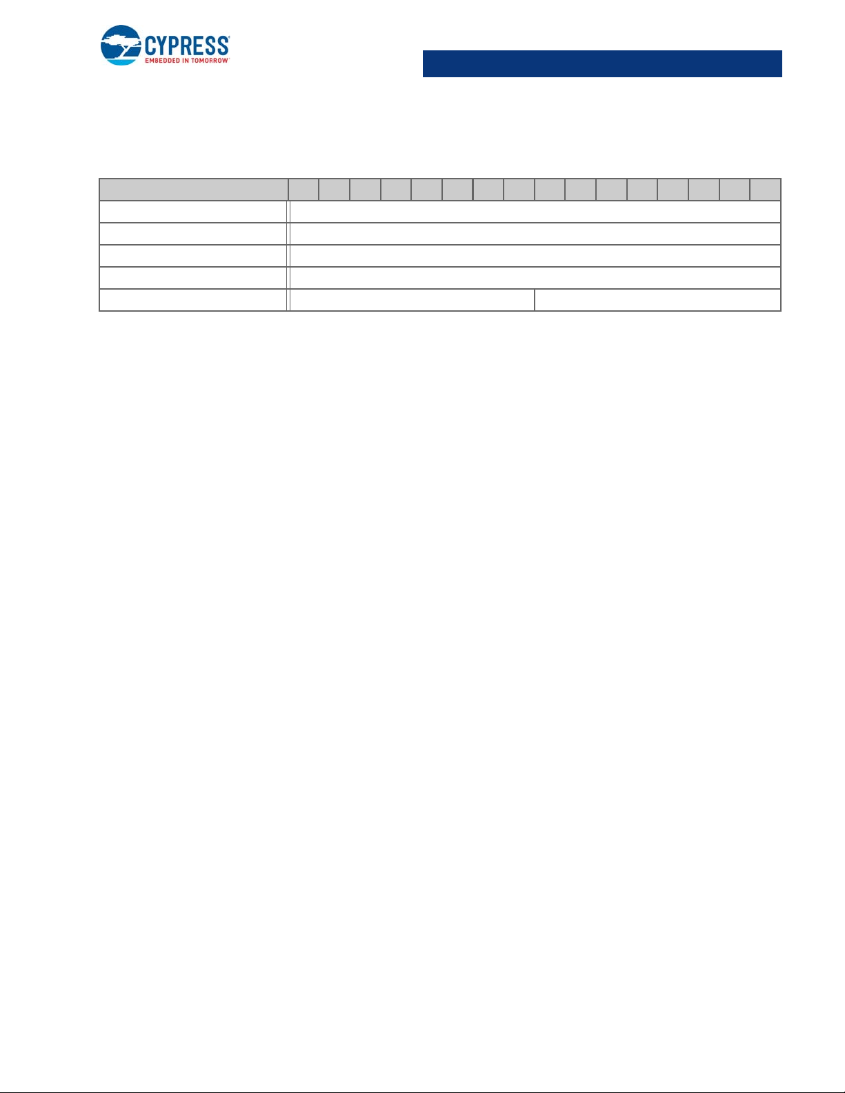
For ease-of-use, this chapter is formatted so that there is one re gister p er page, although some re gisters use two pages. On
each page, from top to bottom, there are four sections:
1. Register name and address (from lowest to highest).
2. Register table showing the bit organization.
3. Written description of register specifics or links to additional register information.
4. Detailed register bit descriptions.
1.2 Register Conventions
The following table lists the register conventions.
Convention Example Description
‘x’ in a register name ACBxxCR1 Multiple instances/address ranges of the same register
R R Read register or bit(s)
W W Write register or bit(s)
NA NA Reserved
None None Not defined
register MSB PROX_TOUCH_TH0 MSB Most significant byte of the register
register LSB PROX_TOUCH_TH0 LSB Least significant byte of the register
- - Byte does not exist
1.3 Endianness
All registers mentioned in the document are little endian.
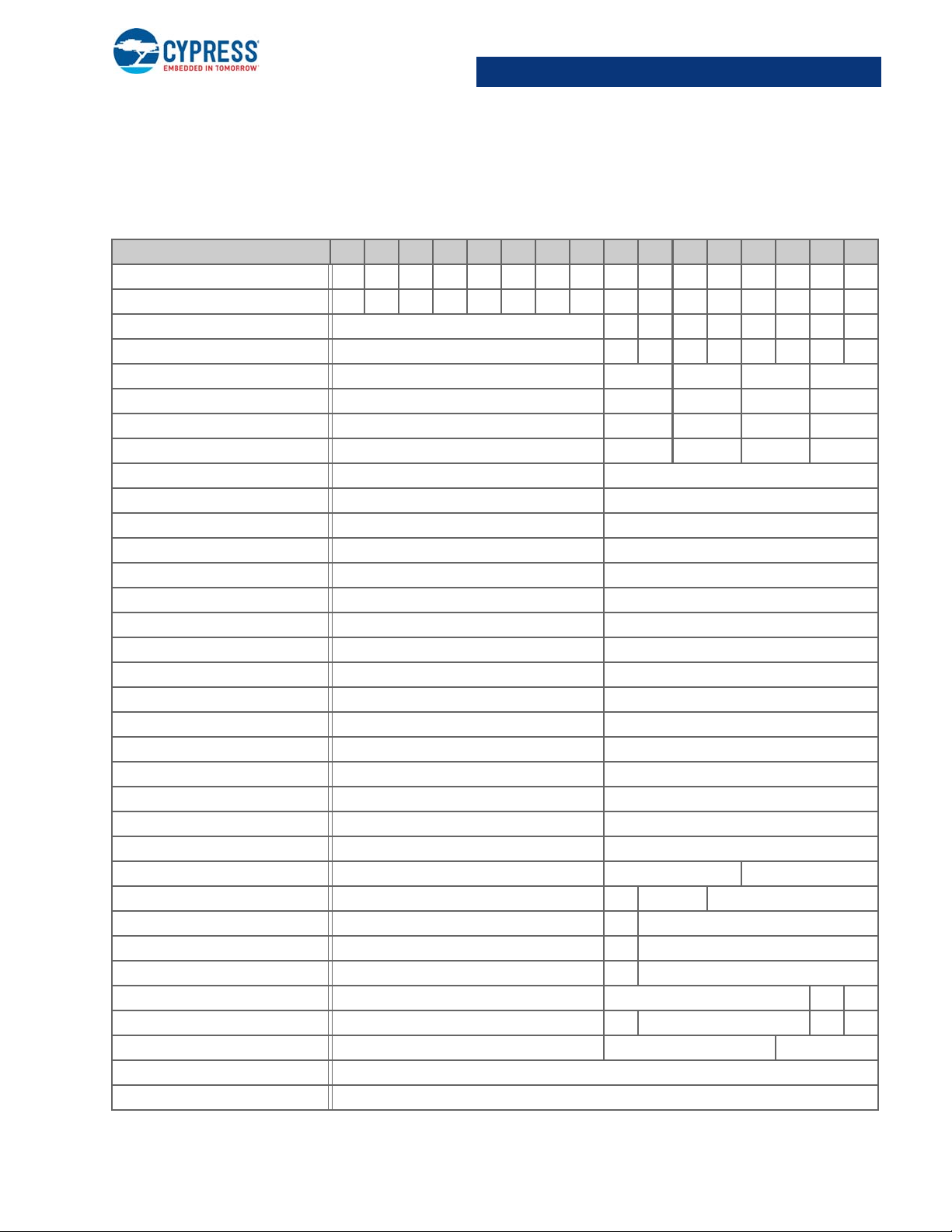
1.4 Factory Default Values
The following tables list the registers applicable to each device and provide the factory default values for configuration regi sters.
CapSense Express Controllers Registers TRM, Document No. 001-91082 Rev. *E 6
Page 7

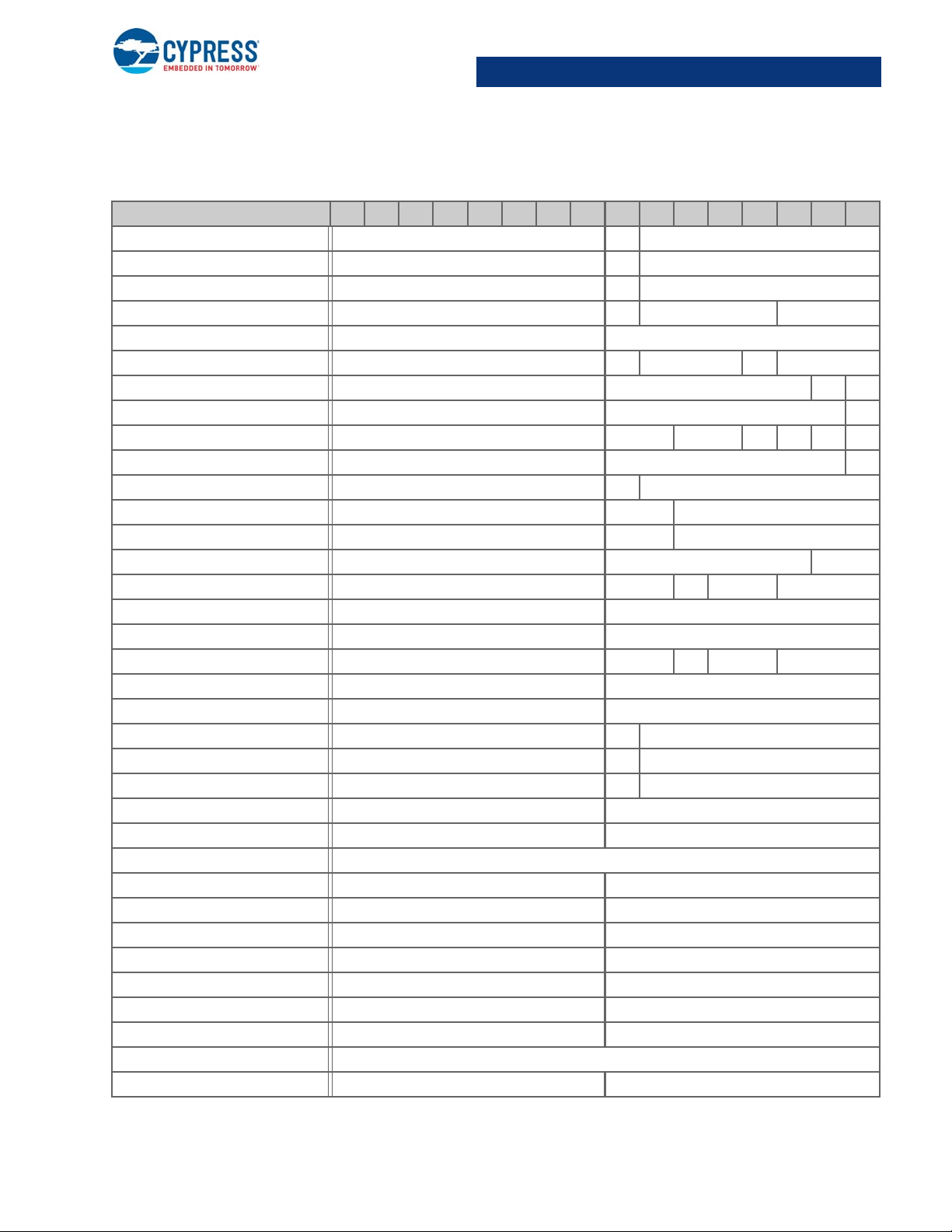
CY8CMBR3102
1.4.1 CY8CMBR3102
Address = CY8CMBR3102
CY8CMBR3102
Register 15 14 13 12 11 10 9 8 7 6 5 4 3 2 1 0
SENSOR_EN NA NA NA NA NA NA NA NA NA NA NA NA NA NA 1 1
FSS_EN NA NA NA NA NA NA NA NA NA NA NA NA NA NA 0 0
TOGGLE_EN NA NA NA NA NA NA NA NA 0
LED_ON_EN NA NANANANANANANA 0
SENSITIVITY0 - NA NA 0 0
BASE_THRESHOLD0 - 128
BASE_THRESHOLD1 - 128
SENSOR_DEBOUNCE - NA 3
BUTTON_HYS - 0 NA 12
BUTTON_LBR - 0 50
BUTTON_NNT - 0 51
BUTTON_NT - 0 51
PROX_EN - NA 0 0
PROX_CFG - 1 NA 0 0
PROX_CFG2 - NA 5
PROX_TOUCH_TH0 512
PROX_TOUCH_TH1 512
PROX_RESOLUTION0 - NA 0
PROX_RESOLUTION1 - NA 0
PROX_HYS - 0 5
PROX_LBR - 0 50
PROX_NNT - 0 20
PROX_NT - 0 20
PROX_POSITIVE_TH0 - 30
PROX_POSITIVE_TH1 - 30
PROX_NEGATIVE_TH0 - 30
PROX_NEGATIVE_TH1 - 30
LED_ON_TIME - NA 0
GPO_CFG - NA 0000
PWM_DUTYCYCLE_CFG0 - 0 15
SPO_CFG - NANANA 1
DEVICE_CFG0 - NA 1 1
DEVICE_CFG1 - NA 1
DEVICE_CFG2 - 0 0 1 0 NA 0
CapSense Express Controllers Registers TRM, Document No. 001-91082 Rev. *E 7
Page 8

CY8CMBR3102
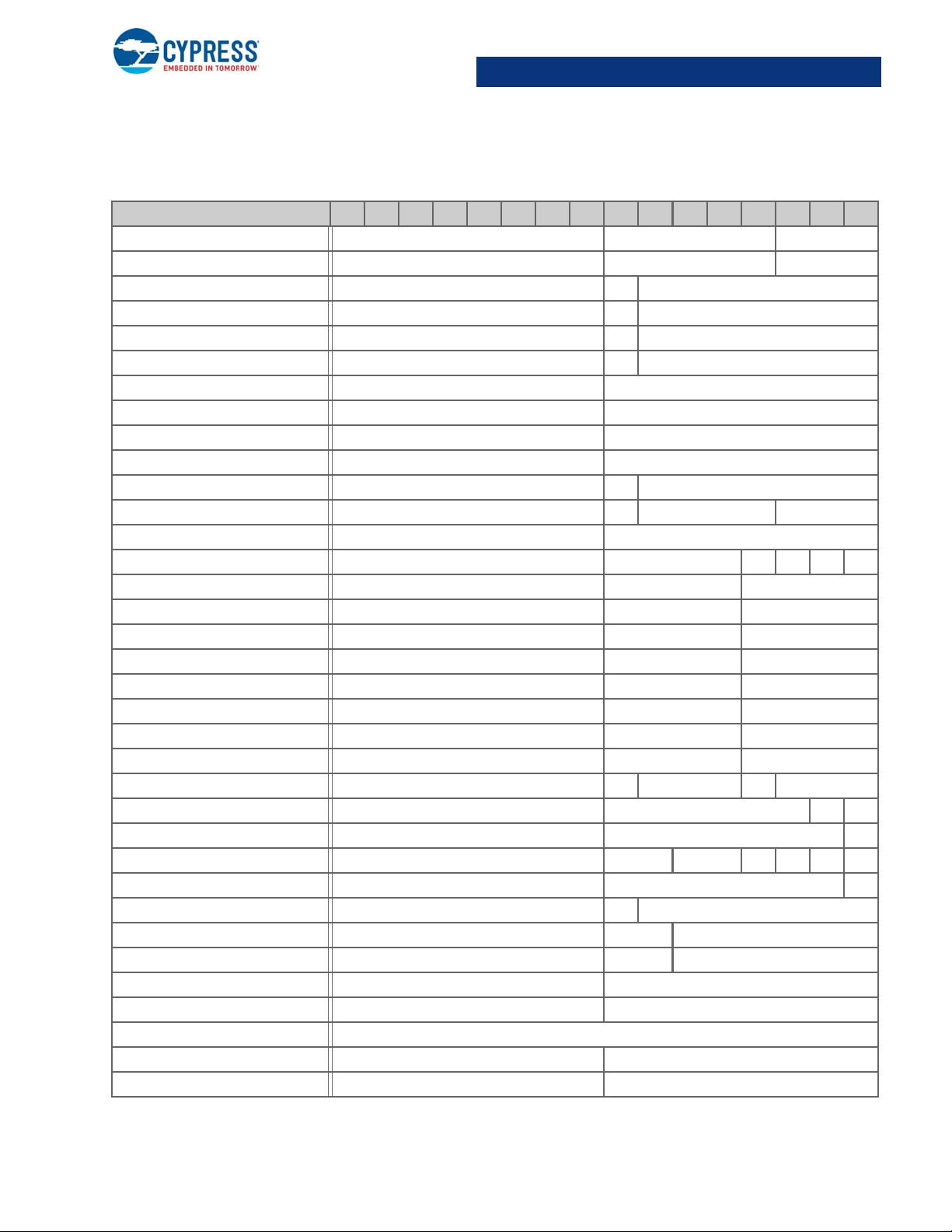
1.4.1 CY8CMBR3102 (continued)
Register 15 14 13 12 11 10 9 8 7 6 5 4 3 2 1 0
DEVICE_CFG3 - NA 0
I2C_ADDR - NA 55
REFRESH_CTRL - NA 6
STATE_TIMEOUT - NA 10
SCRATCHPAD0 - 0
SCRATCHPAD1 - 0
CONFIG_CRC None
GPO_OUTPUT_STATE - None
SENSOR_ID - None
CTRL_CMD - None
CTRL_CMD_STATUS - None
CTRL_CMD_ERR - None
SYSTEM_STATUS - None
PREV_CTRL_CMD_CODE - None
FAMILY_ID - 154
DEVICE_ID 2561
DEVICE_REV NA 1
CALC_CRC None
TOTAL_WORKING_SNS - None
SNS_CP_HIGH None
SNS_VDD_SHORT None
SNS_GND_SHORT None
SNS_SNS_SHORT None
CMOD_SHIELD_TEST - None
BUTTON_STAT None
LATCHED_BUTTON_STAT None
PROX_STAT - None
LATCHED_PROX_STAT - None
SYNC_COUNTER0 - None
DIFFERENCE_COUNT_SENSOR0 None
DIFFERENCE_COUNT_SENSOR1 None
GPO_DATA - None
SYNC_COUNTER1 - None
DEBUG_SENSOR_ID - None
DEBUG_CP - None
CapSense Express Controllers Registers TRM, Document No. 001-91082 Rev. *E 8
Page 9
1.4.1 CY8CMBR3102 (continued)
Register 15 14 13 12 11 10 9 8 7 6 5 4 3 2 1 0
DEBUG_DIFFERENCE_COUNT0 None
DEBUG_BASELINE0 None
DEBUG_RAW_COUNT0 None
DEBUG_AVG_RAW_COUNT0 None
SYNC_COUNTER2 - None
CY8CMBR3102
CapSense Express Controllers Registers TRM, Document No. 001-91082 Rev. *E 9
Page 10

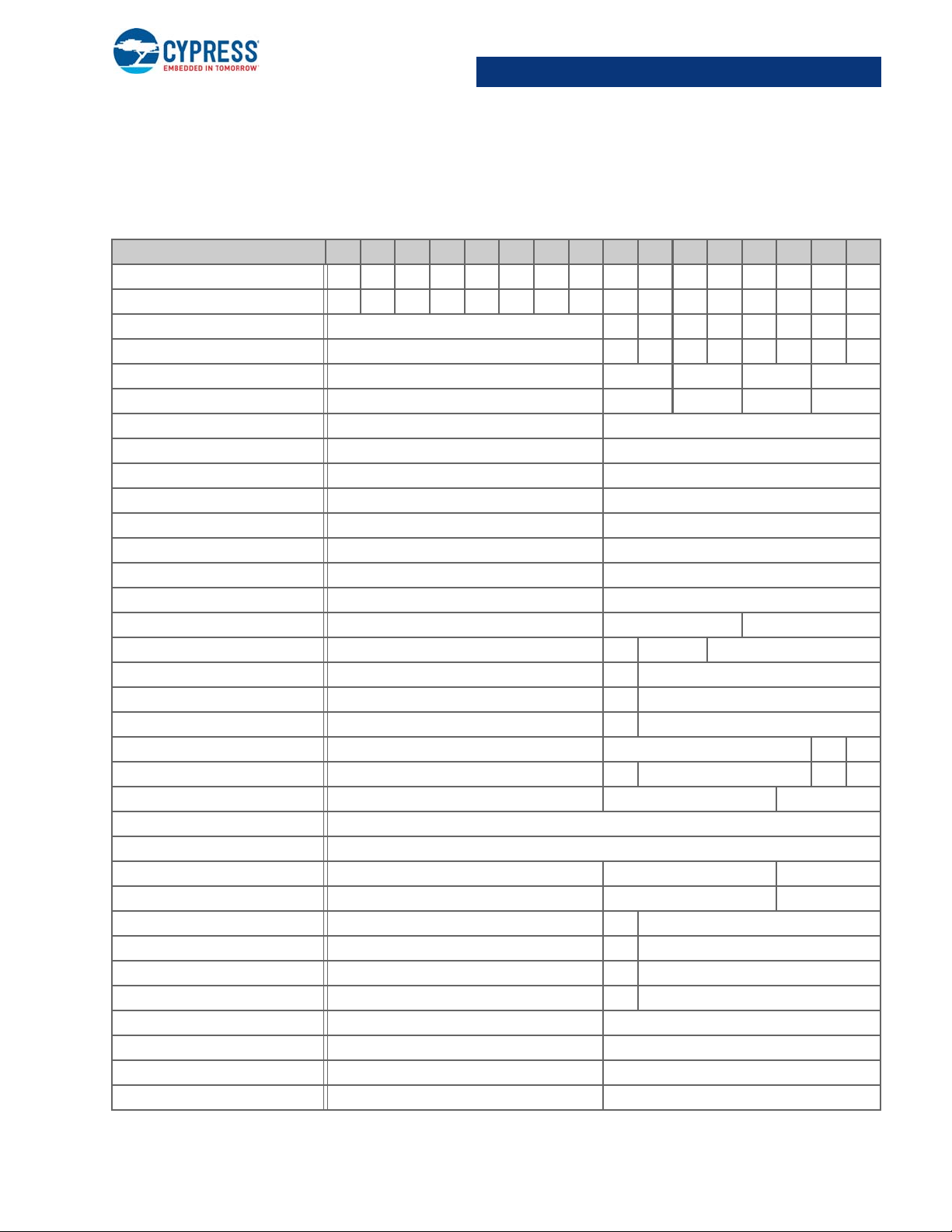
CY8CMBR3106S
1.4.2 CY8CMBR3106S
Address = CY8CMBR3106S
CY8CMBR3106S
Register 15 14 13 12 11 10 9 8 7 6 5 4 3 2 1 0
SENSOR_EN 0 0 0 0 0 NANANANANA 1 1 1 1 1 1
FSS_EN 0 0 0 0 0 NANANANANA 0 0 0 0 0 0
SENSITIVITY0 - 0 0 0 0
SENSITIVITY1 - 0 0 0 0
SENSITIVITY2 - 0 0 0 0
SENSITIVITY3 - 0 0 0 0
BASE_THRESHOLD0 - 128
BASE_THRESHOLD1 - 128
FINGER_THRESHOLD2 - 128
FINGER_THRESHOLD3 - 128
FINGER_THRESHOLD4 - 128
FINGER_THRESHOLD5 - 128
FINGER_THRESHOLD6 - 128
FINGER_THRESHOLD7 - 128
FINGER_THRESHOLD8 - 128
FINGER_THRESHOLD9 - 128
FINGER_THRESHOLD10 - 128
FINGER_THRESHOLD11 - 128
FINGER_THRESHOLD12 - 128
FINGER_THRESHOLD13 - 128
FINGER_THRESHOLD14 - 128
FINGER_THRESHOLD15 - 128
SENSOR_DEBOUNCE - NA 3
BUTTON_HYS - 0 NA 12
BUTTON_LBR - 0 50
BUTTON_NNT - 0 51
BUTTON_NT - 0 51
PROX_EN - NA 0 0
PROX_CFG - NA NA 0 0
PROX_TOUCH_TH0 512
PROX_TOUCH_TH1 512
PROX_RESOLUTION0 - NA 0
PROX_RESOLUTION1 - NA 0
PROX_HYS - 0 5
CapSense Express Controllers Registers TRM, Document No. 001-91082 Rev. *E 10
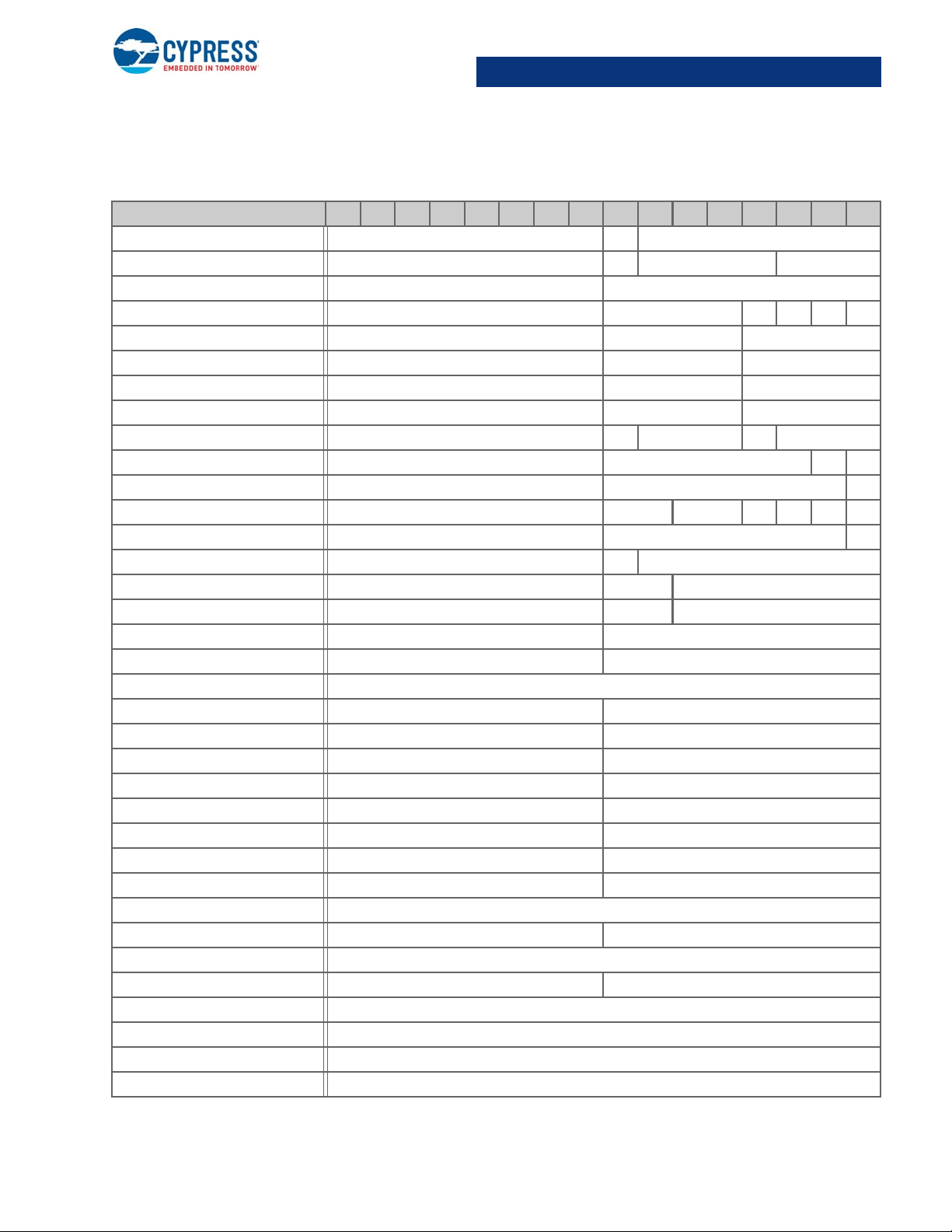
Page 11
CY8CMBR3106S
1.4.2 CY8CMBR3106S (continued)
Register 15 14 13 12 11 10 9 8 7 6 5 4 3 2 1 0
PROX_LBR - 0 50
PROX_NNT - 0 20
PROX_NT - 0 20
BUZZER_CFG - 0 NA 1
BUZZER_ON_TIME - 1
SPO_CFG - NA 1 NA 4
DEVICE_CFG0 - NA 1 1
DEVICE_CFG1 - NA 1
DEVICE_CFG2 - 0 0 1000
DEVICE_CFG3 - NA 0
I2C_ADDR - NA 55
REFRESH_CTRL - NA 6
STATE_TIMEOUT - NA 10
SLIDER_CFG - NA 1
SLIDER1_CFG - NA 0 0 5
SLIDER1_RESOLUTION - 45
SLIDER1_THRESHOLD - 128
SLIDER2_CFG - NA 0 0 5
SLIDER2_RESOLUTION - 45
SLIDER2_THRESHOLD - 128
SLIDER_LBR - 0 0
SLIDER_NNT - 0 0
SLIDER_NT - 0 0
SCRATCHPAD0 - 0
SCRATCHPAD1 - 0
CONFIG_CRC None
SENSOR_ID - None
CTRL_CMD - None
CTRL_CMD_STATUS - None
CTRL_CMD_ERR - None
SYSTEM_STATUS - None
PREV_CTRL_CMD_CODE - None
FAMILY_ID - 154
DEVICE_ID 2566
DEVICE_REV NA 1
CapSense Express Controllers Registers TRM, Document No. 001-91082 Rev. *E 11
Page 12

1.4.2 CY8CMBR3106S (continued)
Register 15 14 13 12 11 10 9 8 7 6 5 4 3 2 1 0
CALC_CRC None
TOTAL_WORKING_SNS - None
SNS_CP_HIGH None
SNS_VDD_SHORT None
SNS_GND_SHORT None
SNS_SNS_SHORT None
CMOD_SHIELD_TEST - None
BUTTON_STAT None
LATCHED_BUTTON_STAT None
PROX_STAT - None
LATCHED_PROX_STAT - None
SLIDER1_POSITION - None
LIFTOFF_SLIDER1_POSITION - None
SLIDER2_POSITION - None
LIFTOFF_SLIDER2_POSITION - None
SYNC_COUNTER0 - None
DIFFERENCE_COUNT_SENSOR0 None
DIFFERENCE_COUNT_SENSOR1 None
DIFFERENCE_COUNT_SENSOR2 None
DIFFERENCE_COUNT_SENSOR3 None
DIFFERENCE_COUNT_SENSOR4 None
DIFFERENCE_COUNT_SENSOR5 None
DIFFERENCE_COUNT_SENSOR6 None
DIFFERENCE_COUNT_SENSOR7 None
DIFFERENCE_COUNT_SENSOR8 None
DIFFERENCE_COUNT_SENSOR9 None
DIFFERENCE_COUNT_SENSOR10 None
DIFFERENCE_COUNT_SENSOR11 None
DIFFERENCE_COUNT_SENSOR12 None
DIFFERENCE_COUNT_SENSOR13 None
DIFFERENCE_COUNT_SENSOR14 None
DIFFERENCE_COUNT_SENSOR15 None
SYNC_COUNTER1 - None
DEBUG_SENSOR_ID - None
DEBUG_CP - None
CY8CMBR3106S
CapSense Express Controllers Registers TRM, Document No. 001-91082 Rev. *E 12
Page 13

1.4.2 CY8CMBR3106S (continued)
Register 15 14 13 12 11 10 9 8 7 6 5 4 3 2 1 0
DEBUG_DIFFERENCE_COUNT0 None
DEBUG_BASELINE0 None
DEBUG_RAW_COUNT0 None
DEBUG_AVG_RAW_COUNT0 None
SYNC_COUNTER2 - None
CY8CMBR3106S
CapSense Express Controllers Registers TRM, Document No. 001-91082 Rev. *E 13
Page 14
CY8CMBR3108
1.4.3 CY8CMBR3108
Address = CY8CMBR3108
CY8CMBR3108
Register 15 14 13 12 11 10 9 8 7 6 5 4 3 2 1 0
SENSOR_EN NANANANANANANANA00001111
FSS_EN NANANANANANANANA00000000
TOGGLE_EN NA NA NA NA NA 0000
LED_ON_EN NA NANANANA0000
SENSITIVITY0 - 0000
SENSITIVITY1 - 0000
BASE_THRESHOLD0 - 128
BASE_THRESHOLD1 - 128
FINGER_THRESHOLD2 - 128
FINGER_THRESHOLD3 - 128
FINGER_THRESHOLD4 - 128
FINGER_THRESHOLD5 - 128
FINGER_THRESHOLD6 - 128
FINGER_THRESHOLD7 - 128
SENSOR_DEBOUNCE - NA 3
BUTTON_HYS - 0 NA 12
BUTTON_LBR - 0 50
BUTTON_NNT - 0 51
BUTTON_NT - 0 51
PROX_EN - NA 0 0
PROX_CFG - 1 NA 0 0
PROX_CFG2 - NA 5
PROX_TOUCH_TH0 512
PROX_TOUCH_TH1 512
PROX_RESOLUTION0 - NA 0
PROX_RESOLUTION1 - NA 0
PROX_HYS - 0 5
PROX_LBR - 0 50
PROX_NNT - 0 20
PROX_NT - 0 20
PROX_POSITIVE_TH0 - 30
PROX_POSITIVE_TH1 - 30
PROX_NEGATIVE_TH0 - 30
PROX_NEGATIVE_TH1 - 30
CapSense Express Controllers Registers TRM, Document No. 001-91082 Rev. *E 14
Page 15
CY8CMBR3108
1.4.3 CY8CMBR3108 (continued)
Register 15 14 13 12 11 10 9 8 7 6 5 4 3 2 1 0
LED_ON_TIME - NA 0
BUZZER_CFG - 0 NA 1
BUZZER_ON_TIME - 1
GPO_CFG - NA 0000
PWM_DUTYCYCLE_CFG0 - 0 15
PWM_DUTYCYCLE_CFG1 - 0 15
PWM_DUTYCYCLE_CFG2 - 0 15
PWM_DUTYCYCLE_CFG3 - 0 15
SPO_CFG - NA 5 NA 4
DEVICE_CFG0 - NA 1 1
DEVICE_CFG1 - NA 1
DEVICE_CFG2 - 0 0 1000
DEVICE_CFG3 - NA 0
I2C_ADDR - NA 55
REFRESH_CTRL - NA 6
STATE_TIMEOUT - NA 10
SCRATCHPAD0 - 0
SCRATCHPAD1 - 0
CONFIG_CRC None
GPO_OUTPUT_STATE - None
SENSOR_ID - None
CTRL_CMD - None
CTRL_CMD_STATUS - None
CTRL_CMD_ERR - None
SYSTEM_STATUS - None
PREV_CTRL_CMD_CODE - None
FAMILY_ID - 154
DEVICE_ID 2563
DEVICE_REV NA 1
CALC_CRC None
TOTAL_WORKING_SNS - None
SNS_CP_HIGH None
SNS_VDD_SHORT None
SNS_GND_SHORT None
SNS_SNS_SHORT None
CapSense Express Controllers Registers TRM, Document No. 001-91082 Rev. *E 15
Page 16

1.4.3 CY8CMBR3108 (continued)
Register 15 14 13 12 11 10 9 8 7 6 5 4 3 2 1 0
CMOD_SHIELD_TEST - None
BUTTON_STAT None
LATCHED_BUTTON_STAT None
PROX_STAT - None
LATCHED_PROX_STAT - None
SYNC_COUNTER0 - None
DIFFERENCE_COUNT_SENSOR0 None
DIFFERENCE_COUNT_SENSOR1 None
DIFFERENCE_COUNT_SENSOR2 None
DIFFERENCE_COUNT_SENSOR3 None
DIFFERENCE_COUNT_SENSOR4 None
DIFFERENCE_COUNT_SENSOR5 None
DIFFERENCE_COUNT_SENSOR6 None
DIFFERENCE_COUNT_SENSOR7 None
GPO_DATA - None
SYNC_COUNTER1 - None
DEBUG_SENSOR_ID - None
DEBUG_CP - None
DEBUG_DIFFERENCE_COUNT0 None
DEBUG_BASELINE0 None
DEBUG_RAW_COUNT0 None
DEBUG_AVG_RAW_COUNT0 None
SYNC_COUNTER2 - None
CY8CMBR3108
CapSense Express Controllers Registers TRM, Document No. 001-91082 Rev. *E 16
Page 17

CY8CMBR3110
1.4.4 CY8CMBR3110
Address = CY8CMBR3110
CY8CMBR3110
Register 15 14 13 12 11 10 9 8 7 6 5 4 3 2 1 0
SENSOR_EN NANANANANANA0000011111
FSS_EN NANANANANANA0000000000
TOGGLE_EN NA NA NA NA 00000
LED_ON_EN NA NANANA00000
SENSITIVITY0 - 0000
SENSITIVITY1 - 0000
SENSITIVITY2 - NA NA 0 0
BASE_THRESHOLD0 - 128
BASE_THRESHOLD1 - 128
FINGER_THRESHOLD2 - 128
FINGER_THRESHOLD3 - 128
FINGER_THRESHOLD4 - 128
FINGER_THRESHOLD5 - 128
FINGER_THRESHOLD6 - 128
FINGER_THRESHOLD7 - 128
FINGER_THRESHOLD8 - 128
FINGER_THRESHOLD9 - 128
SENSOR_DEBOUNCE - NA 3
BUTTON_HYS - 0 NA 12
BUTTON_LBR - 0 50
BUTTON_NNT - 0 51
BUTTON_NT - 0 51
PROX_EN - NA 0 0
PROX_CFG - 1 NA 0 0
PROX_CFG2 - NA 5
PROX_TOUCH_TH0 512
PROX_TOUCH_TH1 512
PROX_RESOLUTION0 - NA 0
PROX_RESOLUTION1 - NA 0
PROX_HYS - 0 5
PROX_LBR - 0 50
PROX_NNT - 0 20
PROX_NT - 0 20
PROX_POSITIVE_TH0 - 30
CapSense Express Controllers Registers TRM, Document No. 001-91082 Rev. *E 17
Page 18

CY8CMBR3110
1.4.4 CY8CMBR3110 (continued)
Register 15 14 13 12 11 10 9 8 7 6 5 4 3 2 1 0
PROX_POSITIVE_TH1 - 30
PROX_NEGATIVE_TH0 - 30
PROX_NEGATIVE_TH1 - 30
LED_ON_TIME - NA 0
BUZZER_CFG - 0 NA 1
BUZZER_ON_TIME - 1
GPO_CFG - NA 0000
PWM_DUTYCYCLE_CFG0 - 0 15
PWM_DUTYCYCLE_CFG1 - 0 15
PWM_DUTYCYCLE_CFG2 - 0 15
PWM_DUTYCYCLE_CFG3 - 0 15
PWM_DUTYCYCLE_CFG4 - 0 15
SPO_CFG - NA 5 NA 1
DEVICE_CFG0 - NA 1 1
DEVICE_CFG1 - NA 1
DEVICE_CFG2 - 0 0 1000
DEVICE_CFG3 - NA 0
I2C_ADDR - NA 55
REFRESH_CTRL - NA 6
STATE_TIMEOUT - NA 10
SCRATCHPAD0 - 0
SCRATCHPAD1 - 0
CONFIG_CRC None
GPO_OUTPUT_STATE - None
SENSOR_ID - None
CTRL_CMD - None
CTRL_CMD_STATUS - None
CTRL_CMD_ERR - None
SYSTEM_STATUS - None
PREV_CTRL_CMD_CODE - None
FAMILY_ID - 154
DEVICE_ID 2562
DEVICE_REV NA 1
CALC_CRC None
TOTAL_WORKING_SNS - None
CapSense Express Controllers Registers TRM, Document No. 001-91082 Rev. *E 18
Page 19

1.4.4 CY8CMBR3110 (continued)
Register 15 14 13 12 11 10 9 8 7 6 5 4 3 2 1 0
SNS_CP_HIGH None
SNS_VDD_SHORT None
SNS_GND_SHORT None
SNS_SNS_SHORT None
CMOD_SHIELD_TEST - None
BUTTON_STAT None
LATCHED_BUTTON_STAT None
PROX_STAT - None
LATCHED_PROX_STAT - None
SYNC_COUNTER0 - None
DIFFERENCE_COUNT_SENSOR0 None
DIFFERENCE_COUNT_SENSOR1 None
DIFFERENCE_COUNT_SENSOR2 None
DIFFERENCE_COUNT_SENSOR3 None
DIFFERENCE_COUNT_SENSOR4 None
DIFFERENCE_COUNT_SENSOR5 None
DIFFERENCE_COUNT_SENSOR6 None
DIFFERENCE_COUNT_SENSOR7 None
DIFFERENCE_COUNT_SENSOR8 None
DIFFERENCE_COUNT_SENSOR9 None
GPO_DATA - None
SYNC_COUNTER1 - None
DEBUG_SENSOR_ID - None
DEBUG_CP - None
DEBUG_DIFFERENCE_COUNT0 None
DEBUG_BASELINE0 None
DEBUG_RAW_COUNT0 None
DEBUG_AVG_RAW_COUNT0 None
SYNC_COUNTER2 - None
CY8CMBR3110
CapSense Express Controllers Registers TRM, Document No. 001-91082 Rev. *E 19
Page 20
CY8CMBR3116
1.4.5 CY8CMBR3116
Address = CY8CMBR3116
CY8CMBR3116
Register 15 14 13 12 11 10 9 8 7 6 5 4 3 2 1 0
SENSOR_EN 0000000011111111
FSS_EN 0000000000000000
TOGGLE_EN NA 0 0 0 0 0 0 0 0
LED_ON_EN NA 00000000
SENSITIVITY0 - 0 0 0 0
SENSITIVITY1 - 0 0 0 0
SENSITIVITY2 - 0 0 0 0
SENSITIVITY3 - 0 0 0 0
BASE_THRESHOLD0 - 128
BASE_THRESHOLD1 - 128
FINGER_THRESHOLD2 - 128
FINGER_THRESHOLD3 - 128
FINGER_THRESHOLD4 - 128
FINGER_THRESHOLD5 - 128
FINGER_THRESHOLD6 - 128
FINGER_THRESHOLD7 - 128
FINGER_THRESHOLD8 - 128
FINGER_THRESHOLD9 - 128
FINGER_THRESHOLD10 - 128
FINGER_THRESHOLD11 - 128
FINGER_THRESHOLD12 - 128
FINGER_THRESHOLD13 - 128
FINGER_THRESHOLD14 - 128
FINGER_THRESHOLD15 - 128
SENSOR_DEBOUNCE - NA 3
BUTTON_HYS - 0 NA 12
BUTTON_LBR - 0 50
BUTTON_NNT - 0 51
BUTTON_NT - 0 51
PROX_EN - NA 0 0
PROX_CFG - 1 NA 0 0
PROX_CFG2 - NA 5
PROX_TOUCH_TH0 512
PROX_TOUCH_TH1 512
CapSense Express Controllers Registers TRM, Document No. 001-91082 Rev. *E 20
Page 21
CY8CMBR3116
1.4.5 CY8CMBR3116 (continued)
Register 15 14 13 12 11 10 9 8 7 6 5 4 3 2 1 0
PROX_RESOLUTION0 - NA 0
PROX_RESOLUTION1 - NA 0
PROX_HYS - 0 5
PROX_LBR - 0 50
PROX_NNT - 0 20
PROX_NT - 0 20
PROX_POSITIVE_TH0 - 30
PROX_POSITIVE_TH1 - 30
PROX_NEGATIVE_TH0 - 30
PROX_NEGATIVE_TH1 - 30
LED_ON_TIME - NA 0
BUZZER_CFG - 0 NA 1
BUZZER_ON_TIME - 1
GPO_CFG - NA 0 0 0 0
PWM_DUTYCYCLE_CFG0 - 0 15
PWM_DUTYCYCLE_CFG1 - 0 15
PWM_DUTYCYCLE_CFG2 - 0 15
PWM_DUTYCYCLE_CFG3 - 0 15
PWM_DUTYCYCLE_CFG4 - 0 15
PWM_DUTYCYCLE_CFG5 - 0 15
PWM_DUTYCYCLE_CFG6 - 0 15
PWM_DUTYCYCLE_CFG7 - 0 15
SPO_CFG - NA 4 NA 5
DEVICE_CFG0 - NA 1 1
DEVICE_CFG1 - NA 1
DEVICE_CFG2 - 0 0 1000
DEVICE_CFG3 - NA 0
I2C_ADDR - NA 55
REFRESH_CTRL - NA 6
STATE_TIMEOUT - NA 10
SCRATCHPAD0 - 0
SCRATCHPAD1 - 0
CONFIG_CRC None
GPO_OUTPUT_STATE - None
SENSOR_ID - None
CapSense Express Controllers Registers TRM, Document No. 001-91082 Rev. *E 21
Page 22

1.4.5 CY8CMBR3116 (continued)
Register 15 14 13 12 11 10 9 8 7 6 5 4 3 2 1 0
CTRL_CMD - None
CTRL_CMD_STATUS - None
CTRL_CMD_ERR - None
SYSTEM_STATUS - None
PREV_CTRL_CMD_CODE - None
FAMILY_ID - 154
DEVICE_ID 2565
DEVICE_REV NA 1
CALC_CRC None
TOTAL_WORKING_SNS - None
SNS_CP_HIGH None
SNS_VDD_SHORT None
SNS_GND_SHORT None
SNS_SNS_SHORT None
CMOD_SHIELD_TEST - None
BUTTON_STAT None
LATCHED_BUTTON_STAT None
PROX_STAT - None
LATCHED_PROX_STAT - None
SYNC_COUNTER0 - None
DIFFERENCE_COUNT_SENSOR0 None
DIFFERENCE_COUNT_SENSOR1 None
DIFFERENCE_COUNT_SENSOR2 None
DIFFERENCE_COUNT_SENSOR3 None
DIFFERENCE_COUNT_SENSOR4 None
DIFFERENCE_COUNT_SENSOR5 None
DIFFERENCE_COUNT_SENSOR6 None
DIFFERENCE_COUNT_SENSOR7 None
DIFFERENCE_COUNT_SENSOR8 None
DIFFERENCE_COUNT_SENSOR9 None
DIFFERENCE_COUNT_SENSOR10 None
DIFFERENCE_COUNT_SENSOR11 None
DIFFERENCE_COUNT_SENSOR12 None
DIFFERENCE_COUNT_SENSOR13 None
DIFFERENCE_COUNT_SENSOR14 None
CY8CMBR3116
CapSense Express Controllers Registers TRM, Document No. 001-91082 Rev. *E 22
Page 23

1.4.5 CY8CMBR3116 (continued)
Register 15 14 13 12 11 10 9 8 7 6 5 4 3 2 1 0
DIFFERENCE_COUNT_SENSOR15 None
GPO_DATA - None
SYNC_COUNTER1 - None
DEBUG_SENSOR_ID - None
DEBUG_CP - None
DEBUG_DIFFERENCE_COUNT0 None
DEBUG_BASELINE0 None
DEBUG_RAW_COUNT0 None
DEBUG_AVG_RAW_COUNT0 None
SYNC_COUNTER2 - None
CY8CMBR3116
CapSense Express Controllers Registers TRM, Document No. 001-91082 Rev. *E 23
Page 24
Register Mapping
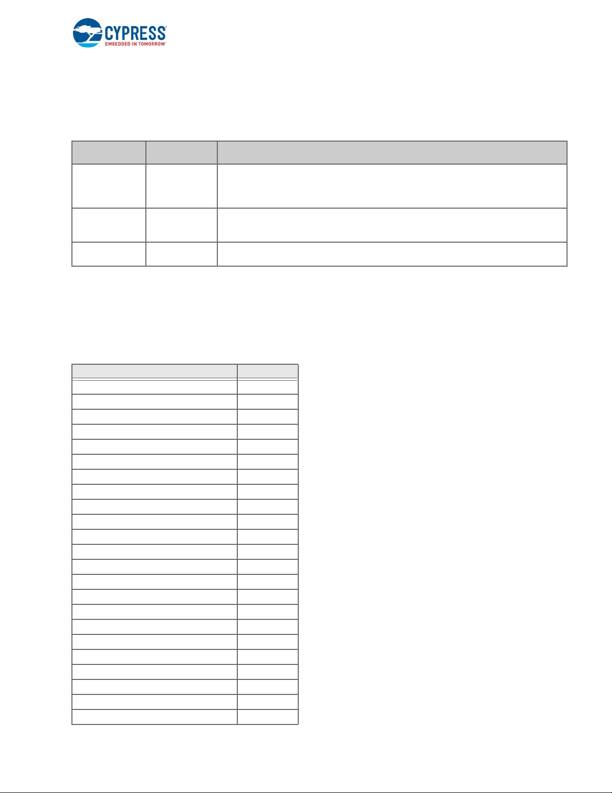
1.5 Register Map
The CY8CMBR3xxx family features an I2C configurable register map. The CY8CMBR3xxx registers are divided into three
categories, as the following table shows.
CY8CMBR3xxx Registers
Register Cate-
gory
Configuration
Registers
Command
Registers
Status Registers 0x88-0xFB These are read only registers and indicate the status of command execution, system
The CY8CMBR3xxx devices feature a safe register map update mechanism to overcome configuration data corruption, which
can occur due to power failure during execution of “Save” command or any other spurious events.
If the configuration data is corrupted when the device is saving data, on the next reset, the devices reconfigure themselves to
the last known valid configuration. If there is no valid con figuratio n saved by u s er, the devices load the factory default config
uration.
The following table provides all registers available in CY8CMBR3xxx family. Refer to Factory Default Values on page 6 for
details on which register is applicable to which device.
Register Map
Address range
Description
0x00-0x7E These registers contain the configuration data for the CY8CMBR3xxx controllers. A host
can write into these registers and save the data to non-volatile memory by writing to
CTRL_CMD command register . Note that the new configuration takes effect only after the
configuration is saved to non-volatile memory and the device is reset.
0x80-0x87 These registers accept commands from host. Any command written to these register is
executed within T
Refer to
CY8CMBR3xxx datasheet for value of TI2C_LATENCY_ MAX.
I2C_LATENCY_ MAX
from the I2C acknowledgement of the command.
diagnostics and sensor data.
-
Register Name Address
SENSOR_EN 0x00
FSS_EN 0x02
TOGGLE_EN 0x04
LED_ON_EN 0x06
SENSITIVITY0 0x08
SENSITIVITY1 0x09
SENSITIVITY2 0x0a
SENSITIVITY3 0x0b
BASE_THRESHOLD0 0x0c
BASE_THRESHOLD1 0x0d
FINGER_THRESHOLD2 0x0e
FINGER_THRESHOLD3 0x0f
FINGER_THRESHOLD4 0x10
FINGER_THRESHOLD5 0x11
FINGER_THRESHOLD6 0x12
FINGER_THRESHOLD7 0x13
FINGER_THRESHOLD8 0x14
FINGER_THRESHOLD9 0x15
FINGER_THRESHOLD10 0x16
FINGER_THRESHOLD11 0x17
FINGER_THRESHOLD12 0x18
FINGER_THRESHOLD13 0x19
FINGER_THRESHOLD14 0x1a
CapSense Express Controllers Registers TRM, Document No. 001-91082 Rev. *E 24
Page 25

Register Name Address
FINGER_THRESHOLD15 0x1b
SENSOR_DEBOUNCE 0x1c
BUTTON_HYS 0x1d
BUTTON_LBR 0x1f
BUTTON_NNT 0x20
BUTTON_NT 0x21
PROX_EN 0x26
PROX_CFG 0x27
PROX_CFG2 0x28
PROX_TOUCH_TH0 0x2a
PROX_TOUCH_TH1 0x2c
PROX_RESOLUTION0 0x2e
PROX_RESOLUTION1 0x2f
PROX_HYS 0x30
PROX_LBR 0x32
PROX_NNT 0x33
PROX_NT 0x34
PROX_POSITIVE_TH0 0x35
PROX_POSITIVE_TH1 0x36
PROX_NEGATIVE_TH0 0x39
PROX_NEGATIVE_TH1 0x3a
LED_ON_TIME 0x3d
BUZZER_CFG 0x3e
BUZZER_ON_TIME 0x3f
GPO_CFG 0x40
PWM_DUTYCYCLE_CFG0 0x41
PWM_DUTYCYCLE_CFG1 0x42
PWM_DUTYCYCLE_CFG2 0x43
PWM_DUTYCYCLE_CFG3 0x44
PWM_DUTYCYCLE_CFG4 0x45
PWM_DUTYCYCLE_CFG5 0x46
PWM_DUTYCYCLE_CFG6 0x47
PWM_DUTYCYCLE_CFG7 0x48
SPO_CFG 0x4c
DEVICE_CFG0 0x4d
DEVICE_CFG1 0x4e
DEVICE_CFG2 0x4f
DEVICE_CFG3 0x50
I2C_ADDR 0x51
REFRESH_CTRL 0x52
STATE_TIMEOUT 0x55
SLIDER_CFG 0x5d
Register Mapping
CapSense Express Controllers Registers TRM, Document No. 001-91082 Rev. *E 25
Page 26

Register Name Address
SLIDER1_CFG 0x61
SLIDER1_RESOLUTION 0x62
SLIDER1_THRESHOLD 0x63
SLIDER2_CFG 0x67
SLIDER2_RESOLUTION 0x68
SLIDER2_THRESHOLD 0x69
SLIDER_LBR 0x71
SLIDER_NNT 0x72
SLIDER_NT 0x73
SCRATCHPAD0 0x7a
SCRATCHPAD1 0x7b
CONFIG_CRC 0x7e
GPO_OUTPUT_STATE 0x80
SENSOR_ID 0x82
CTRL_CMD 0x86
CTRL_CMD_STATUS 0x88
CTRL_CMD_ERR 0x89
SYSTEM_STATUS 0x8a
PREV_CTRL_CMD_CODE 0x8c
FAMILY_ID 0x8f
DEVICE_ID 0x90
DEVICE_REV 0x92
CALC_CRC 0x94
TOTAL_WORKING_SNS 0x97
SNS_CP_HIGH 0x98
SNS_VDD_SHORT 0x9a
SNS_GND_SHORT 0x9c
SNS_SNS_SHORT 0x9e
CMOD_SHIELD_TEST 0xa0
BUTTON_STAT 0xaa
LATCHED_BUTTON_STAT 0xac
PROX_STAT 0xae
LATCHED_PROX_STAT 0xaf
SLIDER1_POSITION 0xb0
LIFTOFF_SLIDER1_POSITION 0xb1
SLIDER2_POSITION 0xb2
LIFTOFF_SLIDER2_POSITION 0xb3
SYNC_COUNTER0 0xb9
DIFFERENCE_COUNT_SENSOR0 0xba
DIFFERENCE_COUNT_SENSOR1 0xbc
DIFFERENCE_COUNT_SENSOR2 0xbe
DIFFERENCE_COUNT_SENSOR3 0xc0
Register Mapping
CapSense Express Controllers Registers TRM, Document No. 001-91082 Rev. *E 26
Page 27

Register Name Address
DIFFERENCE_COUNT_SENSOR4 0xc2
DIFFERENCE_COUNT_SENSOR5 0xc4
DIFFERENCE_COUNT_SENSOR6 0xc6
DIFFERENCE_COUNT_SENSOR7 0xc8
DIFFERENCE_COUNT_SENSOR8 0xca
DIFFERENCE_COUNT_SENSOR9 0xcc
DIFFERENCE_COUNT_SENSOR10 0xce
DIFFERENCE_COUNT_SENSOR11 0xd0
DIFFERENCE_COUNT_SENSOR12 0xd2
DIFFERENCE_COUNT_SENSOR13 0xd4
DIFFERENCE_COUNT_SENSOR14 0xd6
DIFFERENCE_COUNT_SENSOR15 0xd8
GPO_DATA 0xda
SYNC_COUNTER1 0xdb
DEBUG_SENSOR_ID 0xdc
DEBUG_CP 0xdd
DEBUG_DIFFERENCE_COUNT0 0xde
DEBUG_BASELINE0 0xe0
DEBUG_RAW_COUNT0 0xe2
DEBUG_AVG_RAW_COUNT0 0xe4
SYNC_COUNTER2 0xe7
Register Mapping
CapSense Express Controllers Registers TRM, Document No. 001-91082 Rev. *E 27
Page 28

SENSOR_EN
0x00
1.5.1 SENSOR_EN
Address = 0x00
Address: 0x00
Bits 15 14 13 12 11 10 9 8
Host Access RW RW RW RW RW RW RW RW
Device Access RW RW RW RW RW RW RW RW
Bit Name CS15 CS14 CS13 CS12 CS11 CS10 CS9 CS8
Bits 76543210
Host Access RW RW RW RW RW RW RW RW
Device Access RW RW RW RW RW RW RW RW
Bit Name CS7 CS6 CS5 CS4 CS3 CS2 CS1 CS0
Capacitive sensor enable/disable configuration. T o configure S pecial Purpose Output pins (marked as SPOx in datasheet pinouts) as sensors, the pin should be configured as sensor in SPO_CFG and enabled in SENSOR_EN register.
Bits Name Description
15 CS15 Capacitive sensor 15 enable. Note that CS15 is SPO1 in part CY8CMBR3116. This bit field is
not applicable for parts CY8CMBR3102, CY8CMBR3108, CY8CMBR3110.
0: Sensor is disabled
1: Sensor is enabled
14 CS14 Capacitive sensor 14 enable. This bit field is not applicable for parts CY8CMBR3102,
13 CS13 Capacitive sensor 13 enable. This bit field is not applicable for parts CY8CMBR3102,
12 CS12 Capacitive sensor 12 enable. This bit field is not applicable for parts CY8CMBR3102,
11 CS11 Capacitive sensor 11 enable. This bit field is not applicable for parts CY8CMBR3102,
10 CS10 Capacitive sensor 10 enable. This bit field is not applicable for parts CY8CMBR3102,
9 CS9 Capacitive sensor 9 enable. Note that CS9 is SPO1 in part CY8CMBR3110. This bit field is not
CY8CMBR3108, CY8CMBR3110.
0: Sensor is disabled
1: Sensor is enabled
CY8CMBR3108, CY8CMBR3110.
0: Sensor is disabled
1: Sensor is enabled
CY8CMBR3108, CY8CMBR3110.
0: Sensor is disabled
1: Sensor is enabled
CY8CMBR3108, CY8CMBR3110.
0: Sensor is disabled
1: Sensor is enabled
CY8CMBR3106S, CY8CMBR3108, CY8CMBR3110.
0: Sensor is disabled
1: Sensor is enabled
applicable for parts CY8CMBR3102, CY8CMBR3106S, CY8CMBR3108.
CapSense Express Controllers Registers TRM, Document No. 001-91082 Rev. *E 28
Page 29

SENSOR_EN
0x00
1.5.1 SENSOR_EN (continued)
0: Sensor is disabled
1: Sensor is enabled
8 CS8 Capacitive sensor 8 enable. This bit field is not applicable for parts CY8CMBR3102,
CY8CMBR3106S, CY8CMBR3108.
0: Sensor is disabled
1: Sensor is enabled
7 CS7 Capacitive sensor 7 enable. Note that CS7 is SPO1 in part CY8CMBR3108. This bit field is not
6 CS6 Capacitive sensor 6 enable. This bit field is not applicable for parts CY8CMBR3102,
5 CS5 Capacitive sensor 5 enable. Note that CS5 is SPO1 in part CY8CMBR3106S. This bit field is not
4 CS4 Capacitive sensor 4 enable. Note that CS4 is SPO0 in part CY8CMBR3110. This bit field is not
3 CS3 Capacitive sensor 3 enable. This bit field is not applicable for part CY8CMBR3102.
2 CS2 Capacitive sensor 2 enable. This bit field is not applicable for part CY8CMBR3102.
1 CS1 Capacitive sensor 1 enable. Note that CS1 is SPO0 in part CY8CMBR3102.
0 CS0 Capacitive sensor 0 enable
applicable for parts CY8CMBR3102, CY8CMBR3106S.
0: Sensor is disabled
1: Sensor is enabled
CY8CMBR3106S.
0: Sensor is disabled
1: Sensor is enabled
applicable for part CY8CMBR3102.
0: Sensor is disabled
1: Sensor is enabled
applicable for part CY8CMBR3102.
0: Sensor is disabled
1: Sensor is enabled
0: Sensor is disabled
1: Sensor is enabled
0: Sensor is disabled
1: Sensor is enabled
0: Sensor is disabled
1: Sensor is enabled
0: Sensor is disabled
1: Sensor is enabled
CapSense Express Controllers Registers TRM, Document No. 001-91082 Rev. *E 29
Page 30

FSS_EN
0x02
1.5.2 FSS_EN
Address = 0x02
Address: 0x02
Bits 15 14 13 12 11 10 9 8
Host Access RW RW RW RW RW RW RW RW
Device Access RW RW RW RW RW RW RW RW
Bit Name CS15 CS14 CS13 CS12 CS11 CS10 CS9 CS8
Bits 76543210
Host Access RW RW RW RW RW RW RW RW
Device Access RW RW RW RW RW RW RW RW
Bit Name CS7 CS6 CS5 CS4 CS3 CS2 CS1 CS0
This register configures inclusion of sensors in the group undergoing Flan king Sensor Suppression (FSS) processing. FSS
should only be enabled on button sensors. If a sensor is co nfigured as proximity, guard or slider sensor, FSS_EN bits corre
sponding to that sensor should be set to 0.
-
Bits Name Description
15 CS15 Sensor 15 button FSS inclusion. This bit field is not applicable for parts CY8CMBR3102,
CY8CMBR3108, CY8CMBR3110.
0: Sensor button status is excluded from FSS processing
1: Sensor button status is included in FSS processing
14 CS14 Sensor 14 button FSS inclusion. This bit field is not applicable for parts CY8CMBR3102,
CY8CMBR3108, CY8CMBR3110.
0: Sensor button status is excluded from FSS processing
1: Sensor button status is included in FSS processing
13 CS13 Sensor 13 button FSS inclusion. This bit field is not applicable for parts CY8CMBR3102,
12 CS12 Sensor 12 button FSS inclusion. This bit field is not applicable for parts CY8CMBR3102,
11 CS11 Sensor 11 button FSS inclusion. This bit field is not applicable for parts CY8CMBR3102,
10 CS10 Sensor 10 button FSS inclusion. This bit field is not applicable for parts CY8CMBR3102,
CY8CMBR3108, CY8CMBR3110.
0: Sensor button status is excluded from FSS processing
1: Sensor button status is included in FSS processing
CY8CMBR3108, CY8CMBR3110.
0: Sensor button status is excluded from FSS processing
1: Sensor button status is included in FSS processing
CY8CMBR3108, CY8CMBR3110.
0: Sensor button status is excluded from FSS processing
1: Sensor button status is included in FSS processing
CY8CMBR3106S, CY8CMBR3108, CY8CMBR3110.
0: Sensor button status is excluded from FSS processing
1: Sensor button status is included in FSS processing
CapSense Express Controllers Registers TRM, Document No. 001-91082 Rev. *E 30
Page 31

1.5.2 FSS_EN (continued)
FSS_EN
0x02
9 CS9 Sensor 9 button FSS inclusion. This bit field is not applicable for parts CY8CMBR3102,
8 CS8 Sensor 8 button FSS inclusion. This bit field is not applicable for parts CY8CMBR3102,
7 CS7 Sensor 7 button FSS inclusion. This bit field is not applicable for parts CY8CMBR3102,
6 CS6 Sensor 6 button FSS inclusion. This bit field is not applicable for parts CY8CMBR3102,
5 CS5 Sensor 5 button FSS inclusion. This bit field is not applicable for part CY8CMBR3102.
4 CS4 Sensor 4 button FSS inclusion. This bit field is not applicable for part CY8CMBR3102.
3 CS3 Sensor 3 button FSS inclusion. This bit field is not applicable for part CY8CMBR3102.
2 CS2 Sensor 2 button FSS inclusion. This bit field is not applicable for part CY8CMBR3102.
1 CS1 Sensor 1 button FSS inclusion
0 CS0 Sensor 0 button FSS inclusion
CY8CMBR3106S, CY8CMBR3108.
0: Sensor button status is excluded from FSS processing
1: Sensor button status is included in FSS processing
CY8CMBR3106S, CY8CMBR3108.
0: Sensor button status is excluded from FSS processing
1: Sensor button status is included in FSS processing
CY8CMBR3106S.
0: Sensor button status is excluded from FSS processing
1: Sensor button status is included in FSS processing
CY8CMBR3106S.
0: Sensor button status is excluded from FSS processing
1: Sensor button status is included in FSS processing
0: Sensor button status is excluded from FSS processing
1: Sensor button status is included in FSS processing
0: Sensor button status is excluded from FSS processing
1: Sensor button status is included in FSS processing
0: Sensor button status is excluded from FSS processing
1: Sensor button status is included in FSS processing
0: Sensor button status is excluded from FSS processing
1: Sensor button status is included in FSS processing
0: Sensor button status is excluded from FSS processing
1: Sensor button status is included in FSS processing
0: Sensor button status is excluded from FSS processing
1: Sensor button status is included in FSS processing
CapSense Express Controllers Registers TRM, Document No. 001-91082 Rev. *E 31
Page 32

TOGGLE_EN
1.5.3 TOGGLE_EN
Address = 0x04
Address: 0x04
Bits 15 14 13 12 11 10 9 8
Host Access RW
Device Access RW
Bit Name RESERVED
Bits 76543210
Host Access RW RW RW RW RW RW RW RW
Device Access RW RW RW RW RW RW RW RW
Bit Name GPO7 GPO6 GPO5 GPO4 GPO3 GPO2 GPO1 GPO0
GPO toggle enable/disable. This register is not applicable for part CY8CMBR3106S.
0x04
Bits Name Description
15 : 8 RESERVED Reserved
7 GPO7 GPO7 toggle enable. This bit field is not applicable for parts CY8CMBR3102, CY8CMBR3106S,
CY8CMBR3108, CY8CMBR3110.
0: GPO toggle is disabled
1: GPO toggle is enabled
6 GPO6 GPO6 toggle enable. This bit field is not applicable for parts CY8CMBR3102, CY8CMBR3106S,
CY8CMBR3108, CY8CMBR3110.
0: GPO toggle is disabled
1: GPO toggle is enabled
5 GPO5 GPO5 toggle enable. This bit field is not applicable for parts CY8CMBR3102, CY8CMBR3106S,
4 GPO4 GPO4 toggle enable. This bit field is not applicable for parts CY8CMBR3102, CY8CMBR3106S,
3 GPO3 GPO3 toggle enable. This bit field is not applicable for parts CY8CMBR3102, CY8CMBR3106S.
2 GPO2 GPO2 toggle enable. This bit field is not applicable for parts CY8CMBR3102, CY8CMBR3106S.
1 GPO1 GPO1 toggle enable. This bit field is not applicable for parts CY8CMBR3102, CY8CMBR3106S.
CY8CMBR3108, CY8CMBR3110.
0: GPO toggle is disabled
1: GPO toggle is enabled
CY8CMBR3108.
0: GPO toggle is disabled
1: GPO toggle is enabled
0: GPO toggle is disabled
1: GPO toggle is enabled
0: GPO toggle is disabled
1: GPO toggle is enabled
0: GPO toggle is disabled
CapSense Express Controllers Registers TRM, Document No. 001-91082 Rev. *E 32
Page 33

1.5.3 TOGGLE_EN (continued)
1: GPO toggle is enabled
0 GPO0 GPO0 toggle enable. This bit field is not applicable for part CY8CMBR3106S.
0: GPO toggle is disabled
1: GPO toggle is enabled
TOGGLE_EN
0x04
CapSense Express Controllers Registers TRM, Document No. 001-91082 Rev. *E 33
Page 34

LED_ON_EN
1.5.4 LED_ON_EN
Address = 0x06
Address: 0x06
Bits 15 14 13 12 11 10 9 8
Host Access RW
Device Access RW
Bit Name RESERVED
Bits 76543210
Host Access RW RW RW RW RW RW RW RW
Device Access RW RW RW RW RW RW RW RW
Bit Name GPO7 GPO6 GPO5 GPO4 GPO3 GPO2 GPO1 GPO0
GPO extended LED ON duration enable/disable. This reg ister is not applicable for part CY8CMBR3106S.
0x06
Bits Name Description
15 : 8 RESERVED Reserved
7 GPO7 GPO7 extended LED ON duration enable. This bit field is not applicable for parts
CY8CMBR3102, CY8CMBR3106S, CY8CMBR3108, CY8CMBR3110.
0: GPO extended LED ON duration is disabled
1: GPO extended LED ON duration is enabled
6 GPO6 GPO6 extended LED ON duration enable. This bit field is not applicable for parts
CY8CMBR3102, CY8CMBR3106S, CY8CMBR3108, CY8CMBR3110.
0: GPO extended LED ON duration is disabled
1: GPO extended LED ON duration is enabled
5 GPO5 GPO5 extended LED ON duration enable. This bit field is not applicable for parts
4 GPO4 GPO4 extended LED ON duration enable. This bit field is not applicable for parts
3 GPO3 GPO3 extended LED ON duration enable. This bit field is not applicable for parts
2 GPO2 GPO2 extended LED ON duration enable. This bit field is not applicable for parts
CY8CMBR3102, CY8CMBR3106S, CY8CMBR3108, CY8CMBR3110.
0: GPO extended LED ON duration is disabled
1: GPO extended LED ON duration is enabled
CY8CMBR3102, CY8CMBR3106S, CY8CMBR3108.
0: GPO extended LED ON duration is disabled
1: GPO extended LED ON duration is enabled
CY8CMBR3102, CY8CMBR3106S.
0: GPO extended LED ON duration is disabled
1: GPO extended LED ON duration is enabled
CY8CMBR3102, CY8CMBR3106S.
0: GPO extended LED ON duration is disabled
1: GPO extended LED ON duration is enabled
CapSense Express Controllers Registers TRM, Document No. 001-91082 Rev. *E 34
Page 35

1.5.4 LED_ON_EN (continued)
LED_ON_EN
0x06
1 GPO1 GPO1 extended LED ON duration enable. This bit field is not applicable for parts
0 GPO0 GPO0 extended LED ON duration enable. This bit field is not applicable for part
CY8CMBR3102, CY8CMBR3106S.
0: GPO extended LED ON duration is disabled
1: GPO extended LED ON duration is enabled
CY8CMBR3106S.
0: GPO extended LED ON duration is disabled
1: GPO extended LED ON duration is enabled
CapSense Express Controllers Registers TRM, Document No. 001-91082 Rev. *E 35
Page 36

1.5.5 SENSITIVITY0
Address = 0x08
Address: 0x08
Bits 76543210
Host Access RW RW RW RW
Device Access RW RW RW RW
Bit Name CS3_SENSITIVITY CS2_SENSITIVITY CS1_SENSITIVITY CS0_SENSITIVITY
Sensitivities (units: counts/pF) for button sensors 0 - 3
Bits Name Description
7 : 6 CS3_SENSITIVITY Sensor 3 sensitivity. This bit field is not applicable for part CY8CMBR3102.
0: 50 counts/0.1 pF
1: 50 counts/0.2 pF
2: 50 counts/0.3 pF
3: 50 counts/0.4 pF
5 : 4 CS2_SENSITIVITY Sensor 2 sensitivity. This bit field is not applicable for part CY8CMBR3102.
0: 50 counts/0.1 pF
1: 50 counts/0.2 pF
2: 50 counts/0.3 pF
3: 50 counts/0.4 pF
3 : 2 CS1_SENSITIVITY Sensor 1 sensitivity
0: 50 counts/0.1 pF
1: 50 counts/0.2 pF
2: 50 counts/0.3 pF
3: 50 counts/0.4 pF
1 : 0 CS0_SENSITIVITY Sensor 0 sensitivity
0: 50 counts/0.1 pF
1: 50 counts/0.2 pF
2: 50 counts/0.3 pF
3: 50 counts/0.4 pF
SENSITIVITY0
0x08
CapSense Express Controllers Registers TRM, Document No. 001-91082 Rev. *E 36
Page 37

1.5.6 SENSITIVITY1
Address = 0x09
Address: 0x09
Bits 76543210
Host Access RW RW RW RW
Device Access RW RW RW RW
Bit Name CS7_SENSITIVITY CS6_SENSITIVITY CS5_SENSITIVITY CS4_SENSITIVITY
Sensitivities (units: counts/pF) for button sensors 4 - 7. This register is not applicable for part CY8CMBR3102.
Bits Name Description
7 : 6 CS7_SENSITIVITY Sensor 7 sensitivity. This bit field is not applicable for part CY8CMBR3102.
0: 50 counts/0.1 pF
1: 50 counts/0.2 pF
2: 50 counts/0.3 pF
3: 50 counts/0.4 pF
5 : 4 CS6_SENSITIVITY Sensor 6 sensitivity. This bit field is not applicable for part CY8CMBR3102.
0: 50 counts/0.1 pF
1: 50 counts/0.2 pF
2: 50 counts/0.3 pF
3: 50 counts/0.4 pF
3 : 2 CS5_SENSITIVITY Sensor 5 sensitivity. This bit field is not applicable for part CY8CMBR3102.
0: 50 counts/0.1 pF
1: 50 counts/0.2 pF
2: 50 counts/0.3 pF
3: 50 counts/0.4 pF
1 : 0 CS4_SENSITIVITY Sensor 4 sensitivity. This bit field is not applicable for part CY8CMBR3102.
0: 50 counts/0.1 pF
1: 50 counts/0.2 pF
2: 50 counts/0.3 pF
3: 50 counts/0.4 pF
SENSITIVITY1
0x09
CapSense Express Controllers Registers TRM, Document No. 001-91082 Rev. *E 37
Page 38

SENSITIVITY2
0x0a
1.5.7 SENSITIVITY2
Address = 0x0a
Address: 0x0a
Bits 76543210
Host Access RW RW RW RW
Device Access RW RW RW RW
Bit Name CS11_SENSITIVITY CS10_SENSITIVITY CS9_SENSITIVITY CS8_SENSITIVITY
Sensitivities (units: counts/pF) for button sensors 8 - 11. This register is not applicable for parts CY8CMBR3102,
CY8CMBR3108.
Bits Name Description
7 : 6 CS11_SENSITIVITY Sensor 11 sensitivity. This bit field is not applicable for parts CY8CMBR3102, CY8CMBR3108,
CY8CMBR3110.
0: 50 counts/0.1 pF
1: 50 counts/0.2 pF
2: 50 counts/0.3 pF
3: 50 counts/0.4 pF
5 : 4 CS10_SENSITIVITY Sensor 10 sensitivity. This bit field is not applicable for parts CY8CMBR3102, CY8CMBR3108,
CY8CMBR3110.
0: 50 counts/0.1 pF
1: 50 counts/0.2 pF
2: 50 counts/0.3 pF
3: 50 counts/0.4 pF
3 : 2 CS9_SENSITIVITY Sensor 9 sensitivity. This bit field is not applicable for parts CY8CMBR3102, CY8CMBR3108.
0: 50 counts/0.1 pF
1: 50 counts/0.2 pF
2: 50 counts/0.3 pF
3: 50 counts/0.4 pF
1 : 0 CS8_SENSITIVITY Sensor 8 sensitivity. This bit field is not applicable for parts CY8CMBR3102, CY8CMBR3108.
0: 50 counts/0.1 pF
1: 50 counts/0.2 pF
2: 50 counts/0.3 pF
3: 50 counts/0.4 pF
CapSense Express Controllers Registers TRM, Document No. 001-91082 Rev. *E 38
Page 39

SENSITIVITY3
0x0b
1.5.8 SENSITIVITY3
Address = 0x0b
Address: 0x0b
Bits 76543210
Host Access RW RW RW RW
Device Access RW RW RW RW
Bit Name CS15_SENSITIVITY CS14_SENSITIVITY CS13_SENSITIVITY CS12_SENSITIVITY
Sensitivities (units: counts/pF) for button sensors 12 - 15. This register is not applicable for parts CY8CMBR3102,
CY8CMBR3108, CY8CMBR3110.
Bits Name Description
7 : 6 CS15_SENSITIVITY Sensor 15 sensitivity. This bit field is not applicable for parts CY8CMBR3102, CY8CMBR3108,
CY8CMBR3110.
0: 50 counts/0.1 pF
1: 50 counts/0.2 pF
2: 50 counts/0.3 pF
3: 50 counts/0.4 pF
5 : 4 CS14_SENSITIVITY Sensor 14 sensitivity. This bit field is not applicable for parts CY8CMBR3102, CY8CMBR3108,
CY8CMBR3110.
0: 50 counts/0.1 pF
1: 50 counts/0.2 pF
2: 50 counts/0.3 pF
3: 50 counts/0.4 pF
3 : 2 CS13_SENSITIVITY Sensor 13 sensitivity. This bit field is not applicable for parts CY8CMBR3102, CY8CMBR3108,
CY8CMBR3110.
0: 50 counts/0.1 pF
1: 50 counts/0.2 pF
2: 50 counts/0.3 pF
3: 50 counts/0.4 pF
1 : 0 CS12_SENSITIVITY Sensor 12 sensitivity. This bit field is not applicable for parts CY8CMBR3102, CY8CMBR3108,
CY8CMBR3110.
0: 50 counts/0.1 pF
1: 50 counts/0.2 pF
2: 50 counts/0.3 pF
3: 50 counts/0.4 pF
CapSense Express Controllers Registers TRM, Document No. 001-91082 Rev. *E 39
Page 40

BASE_THRESHOLD0
0x0c
1.5.9 BASE_THRESHOLD0
Address = 0x0c
Address: 0x0c
Bits 76543210
Host Access RW
Device Access RW
Bit Name BASE_THRESHOLD0
Finger threshold (units: counts) for sensor 0. This threshold is applied when sensor 0 is co nfigured as a button sensor and
automatic threshold mode is disabled. This threshold is also applied when EMC is en abled, as automatic threshold is disabled when EMC is enabled. This threshold is applied as proximity threshold when sensor 0 is configured as a proximity sensor. When sensor 0 is configured as a proximity sensor, the value of this register must be set lower than the value of
PROX_TOUCH_TH0. If this rule is not followed, system behavior is undefined
Bits Name Description
7 : 0 BASE_THRESHOLD0 Finger threshold (units: counts) for sensor 0. This threshold is applied when sensor 0 is config-
ured as a button sensor and automatic threshold mode is disabled. This threshold is also applied
when EMC is enabled, as automatic threshold is disabled when EMC is enabled. This threshold
is applied as proximity threshold when sensor 0 is configured as a proximity sensor. When sensor 0 is configured as a proximity sensor, the value of this register must be set lower than the
value of PROX_TOUCH_TH0. If this rule is not followed, system behavior is undefined. The valid
value of this bit field ranges from 31 to 200.
CapSense Express Controllers Registers TRM, Document No. 001-91082 Rev. *E 40
Page 41

BASE_THRESHOLD1
0x0d
1.5.10 BASE_THRESHOLD1
Address = 0x0d
Address: 0x0d
Bits 76543210
Host Access RW
Device Access RW
Bit Name BASE_THRESHOLD1
Finger threshold (units: counts) for sensor 1. This threshold is applied when sensor 1 is co nfigured as a button sensor and
automatic threshold mode is disabled. This threshold is also applied when EMC is en abled, as automatic threshold is disabled when EMC is enabled. This threshold is applied as proximity threshold for sensor 1 when it is configured as a proximity
sensor. When sensor 1 is configured as a proximity sensor, the value of this register must be set lower than the value of
PROX_TOUCH_TH1. If this rule is not followed, system behavior is undefined
Bits Name Description
7 : 0 BASE_THRESHOLD1 Finger threshold (units: counts) for sensor 1. This threshold is applied when sensor 1 is config-
ured as a button sensor and automatic threshold mode is disabled. This threshold is also applied
when EMC is enabled, as automatic threshold is disabled when EMC is enabled. This threshold
is applied as proximity threshold for sensor 1 when it is configured as a proximity sensor. When
sensor 1 is configured as a proximity sensor, the value of this register must be set lower than the
value of PROX_TOUCH_TH1. If this rule is not followed, system behavior is undefined. The valid
value of this bit field ranges from 31 to 200.
CapSense Express Controllers Registers TRM, Document No. 001-91082 Rev. *E 41
Page 42

FINGER_THRESHOLD2
0x0e
1.5.11 FINGER_THRESHOLD2
Address = 0x0e
Address: 0x0e
Bits 76543210
Host Access RW
Device Access RW
Bit Name FINGER_THRESHOLD2
Finger threshold (units: counts) applied for sensor 2 when automatic threshold mode is disabled. Note that this threshold is
also applied when EMC is enabled, as automatic threshold is d isabled when EMC is enabled. T his register is no t applicable
for part CY8CMBR3102.
Bits Name Description
7 : 0 FINGER_THRESHOLD2 Finger threshold (units: counts) applied for sensor 2 when automatic threshold mode is disabled.
Note that this threshold is also applied when EMC is enabled, as automatic threshold is disabled
when EMC is enabled. The valid value of this bit field ranges from 31 to 200. This bit field is not
applicable for part CY8CMBR3102.
CapSense Express Controllers Registers TRM, Document No. 001-91082 Rev. *E 42
Page 43

FINGER_THRESHOLD3
0x0f
1.5.12 FINGER_THRESHOLD3
Address = 0x0f
Address: 0x0f
Bits 76543210
Host Access RW
Device Access RW
Bit Name FINGER_THRESHOLD3
Finger threshold (units: counts) applied for sensor 3 when automatic threshold mode is disabled. Note that this threshold is
also applied when EMC is enabled, as automatic threshold is d isabled when EMC is enabled. T his register is no t applicable
for part CY8CMBR3102.
Bits Name Description
7 : 0 FINGER_THRESHOLD3 Finger threshold (units: counts) applied for sensor 3 when automatic threshold mode is disabled.
Note that this threshold is also applied when EMC is enabled, as automatic threshold is disabled
when EMC is enabled. The valid value of this bit field ranges from 31 to 200. This bit field is not
applicable for part CY8CMBR3102.
CapSense Express Controllers Registers TRM, Document No. 001-91082 Rev. *E 43
Page 44

FINGER_THRESHOLD4
0x10
1.5.13 FINGER_THRESHOLD4
Address = 0x10
Address: 0x10
Bits 76543210
Host Access RW
Device Access RW
Bit Name FINGER_THRESHOLD4
Finger threshold (units: counts) applied for sensor 4 when automatic threshold mode is disabled. Note that this threshold is
also applied when EMC is enabled, as automatic threshold is d isabled when EMC is enabled. T his register is no t applicable
for part CY8CMBR3102.
Bits Name Description
7 : 0 FINGER_THRESHOLD4 Finger threshold (units: counts) applied for sensor 4 when automatic threshold mode is disabled.
Note that this threshold is also applied when EMC is enabled, as automatic threshold is disabled
when EMC is enabled. The valid value of this bit field ranges from 31 to 200. This bit field is not
applicable for part CY8CMBR3102.
CapSense Express Controllers Registers TRM, Document No. 001-91082 Rev. *E 44
Page 45

FINGER_THRESHOLD5
0x11
1.5.14 FINGER_THRESHOLD5
Address = 0x11
Address: 0x11
Bits 76543210
Host Access RW
Device Access RW
Bit Name FINGER_THRESHOLD5
Finger threshold (units: counts) applied for sensor 5 when automatic threshold mode is disabled. Note that this threshold is
also applied when EMC is enabled, as automatic threshold is d isabled when EMC is enabled. T his register is no t applicable
for part CY8CMBR3102.
Bits Name Description
7 : 0 FINGER_THRESHOLD5 Finger threshold (units: counts) applied for sensor 5 when automatic threshold mode is disabled.
Note that this threshold is also applied when EMC is enabled, as automatic threshold is disabled
when EMC is enabled. The valid value of this bit field ranges from 31 to 200. This bit field is not
applicable for part CY8CMBR3102.
CapSense Express Controllers Registers TRM, Document No. 001-91082 Rev. *E 45
Page 46

FINGER_THRESHOLD6
0x12
1.5.15 FINGER_THRESHOLD6
Address = 0x12
Address: 0x12
Bits 76543210
Host Access RW
Device Access RW
Bit Name FINGER_THRESHOLD6
Finger threshold (units: counts) applied for sensor 6 when automatic threshold mode is disabled. Note that this threshold is
also applied when EMC is enabled, as automatic threshold is d isabled when EMC is enabled. T his register is no t applicable
for part CY8CMBR3102.
Bits Name Description
7 : 0 FINGER_THRESHOLD6 Finger threshold (units: counts) applied for sensor 6 when automatic threshold mode is disabled.
Note that this threshold is also applied when EMC is enabled, as automatic threshold is disabled
when EMC is enabled. The valid value of this bit field ranges from 31 to 200. This bit field is not
applicable for part CY8CMBR3102.
CapSense Express Controllers Registers TRM, Document No. 001-91082 Rev. *E 46
Page 47

FINGER_THRESHOLD7
0x13
1.5.16 FINGER_THRESHOLD7
Address = 0x13
Address: 0x13
Bits 76543210
Host Access RW
Device Access RW
Bit Name FINGER_THRESHOLD7
Finger threshold (units: counts) applied for sensor 7 when automatic threshold mode is disabled. Note that this threshold is
also applied when EMC is enabled, as automatic threshold is d isabled when EMC is enabled. T his register is no t applicable
for part CY8CMBR3102.
Bits Name Description
7 : 0 FINGER_THRESHOLD7 Finger threshold (units: counts) applied for sensor 7 when automatic threshold mode is disabled.
Note that this threshold is also applied when EMC is enabled, as automatic threshold is disabled
when EMC is enabled. The valid value of this bit field ranges from 31 to 200. This bit field is not
applicable for part CY8CMBR3102.
CapSense Express Controllers Registers TRM, Document No. 001-91082 Rev. *E 47
Page 48

FINGER_THRESHOLD8
0x14
1.5.17 FINGER_THRESHOLD8
Address = 0x14
Address: 0x14
Bits 76543210
Host Access RW
Device Access RW
Bit Name FINGER_THRESHOLD8
Finger threshold (units: counts) applied for sensor 8 when automatic threshold mode is disabled. Note that this threshold is
also applied when EMC is enabled, as automatic threshold is d isabled when EMC is enabled. T his register is no t applicable
for parts CY8CMBR3102, CY8CMBR3108.
Bits Name Description
7 : 0 FINGER_THRESHOLD8 Finger threshold (units: counts) applied for sensor 8 when automatic threshold mode is disabled.
Note that this threshold is also applied when EMC is enabled, as automatic threshold is disabled
when EMC is enabled. The valid value of this bit field ranges from 31 to 200. This bit field is not
applicable for parts CY8CMBR3102, CY8CMBR3108.
CapSense Express Controllers Registers TRM, Document No. 001-91082 Rev. *E 48
Page 49

FINGER_THRESHOLD9
0x15
1.5.18 FINGER_THRESHOLD9
Address = 0x15
Address: 0x15
Bits 76543210
Host Access RW
Device Access RW
Bit Name FINGER_THRESHOLD9
Finger threshold (units: counts) applied for sensor 9 when automatic threshold mode is disabled. Note that this threshold is
also applied when EMC is enabled, as automatic threshold is d isabled when EMC is enabled. T his register is no t applicable
for parts CY8CMBR3102, CY8CMBR3108.
Bits Name Description
7 : 0 FINGER_THRESHOLD9 Finger threshold (units: counts) applied for sensor 9 when automatic threshold mode is disabled.
Note that this threshold is also applied when EMC is enabled, as automatic threshold is disabled
when EMC is enabled. The valid value of this bit field ranges from 31 to 200. This bit field is not
applicable for parts CY8CMBR3102, CY8CMBR3108.
CapSense Express Controllers Registers TRM, Document No. 001-91082 Rev. *E 49
Page 50

FINGER_THRESHOLD10
0x16
1.5.19 FINGER_THRESHOLD10
Address = 0x16
Address: 0x16
Bits 76543210
Host Access RW
Device Access RW
Bit Name FINGER_THRESHOLD10
Finger threshold (units: counts) applied for sensor 10 when automatic thre shold mo de is disabled. No te that this th reshold is
also applied when EMC is enabled, as automatic threshold is d isabled when EMC is enabled. T his register is no t applicable
for parts CY8CMBR3102, CY8CMBR3108, CY8CMBR3110.
Bits Name Description
7 : 0 FINGER_THRESHOLD10 Finger threshold (units: counts) applied for sensor 10 when automatic threshold mode is dis-
abled. Note that this threshold is also applied when EMC is enabled, as automatic threshold is
disabled when EMC is enabled. The valid value of this bit field ranges from 31 to 200. This bit
field is not applicable for parts CY8CMBR3102, CY8CMBR3108, CY8CMBR3110.
CapSense Express Controllers Registers TRM, Document No. 001-91082 Rev. *E 50
Page 51

FINGER_THRESHOLD11
0x17
1.5.20 FINGER_THRESHOLD11
Address = 0x17
Address: 0x17
Bits 76543210
Host Access RW
Device Access RW
Bit Name FINGER_THRESHOLD11
Finger threshold (units: counts) applied for sensor 11 when automatic threshold mode is disabled. Note that this threshold is
also applied when EMC is enabled, as automatic threshold is d isabled when EMC is enabled. T his register is no t applicable
for parts CY8CMBR3102, CY8CMBR3108, CY8CMBR3110.
Bits Name Description
7 : 0 FINGER_THRESHOLD11 Finger threshold (units: counts) applied for sensor 11 when automatic threshold mode is dis-
abled. Note that this threshold is also applied when EMC is enabled, as automatic threshold is
disabled when EMC is enabled. The valid value of this bit field ranges from 31 to 200. This bit
field is not applicable for parts CY8CMBR3102, CY8CMBR3108, CY8CMBR3110.
CapSense Express Controllers Registers TRM, Document No. 001-91082 Rev. *E 51
Page 52

FINGER_THRESHOLD12
0x18
1.5.21 FINGER_THRESHOLD12
Address = 0x18
Address: 0x18
Bits 76543210
Host Access RW
Device Access RW
Bit Name FINGER_THRESHOLD12
Finger threshold (units: counts) applied for sensor 12 when automatic thre shold mo de is disabled. No te that this th reshold is
also applied when EMC is enabled, as automatic threshold is d isabled when EMC is enabled. T his register is no t applicable
for parts CY8CMBR3102, CY8CMBR3108, CY8CMBR3110.
Bits Name Description
7 : 0 FINGER_THRESHOLD12 Finger threshold (units: counts) applied for sensor 12 when automatic threshold mode is dis-
abled. Note that this threshold is also applied when EMC is enabled, as automatic threshold is
disabled when EMC is enabled. The valid value of this bit field ranges from 31 to 200. This bit
field is not applicable for parts CY8CMBR3102, CY8CMBR3108, CY8CMBR3110.
CapSense Express Controllers Registers TRM, Document No. 001-91082 Rev. *E 52
Page 53

FINGER_THRESHOLD13
0x19
1.5.22 FINGER_THRESHOLD13
Address = 0x19
Address: 0x19
Bits 76543210
Host Access RW
Device Access RW
Bit Name FINGER_THRESHOLD13
Finger threshold (units: counts) applied for sensor 13 when automatic thre shold mo de is disabled. No te that this th reshold is
also applied when EMC is enabled, as automatic threshold is d isabled when EMC is enabled. T his register is no t applicable
for parts CY8CMBR3102, CY8CMBR3108, CY8CMBR3110.
Bits Name Description
7 : 0 FINGER_THRESHOLD13 Finger threshold (units: counts) applied for sensor 13 when automatic threshold mode is dis-
abled. Note that this threshold is also applied when EMC is enabled, as automatic threshold is
disabled when EMC is enabled. The valid value of this bit field ranges from 31 to 200. This bit
field is not applicable for parts CY8CMBR3102, CY8CMBR3108, CY8CMBR3110.
CapSense Express Controllers Registers TRM, Document No. 001-91082 Rev. *E 53
Page 54

FINGER_THRESHOLD14
0x1a
1.5.23 FINGER_THRESHOLD14
Address = 0x1a
Address: 0x1a
Bits 76543210
Host Access RW
Device Access RW
Bit Name FINGER_THRESHOLD14
Finger threshold (units: counts) applied for sensor 14 when automatic thre shold mo de is disabled. No te that this th reshold is
also applied when EMC is enabled, as automatic threshold is d isabled when EMC is enabled. T his register is no t applicable
for parts CY8CMBR3102, CY8CMBR3108, CY8CMBR3110.
Bits Name Description
7 : 0 FINGER_THRESHOLD14 Finger threshold (units: counts) applied for sensor 14 when automatic threshold mode is dis-
abled. Note that this threshold is also applied when EMC is enabled, as automatic threshold is
disabled when EMC is enabled. The valid value of this bit field ranges from 31 to 200. This bit
field is not applicable for parts CY8CMBR3102, CY8CMBR3108, CY8CMBR3110.
CapSense Express Controllers Registers TRM, Document No. 001-91082 Rev. *E 54
Page 55

FINGER_THRESHOLD15
0x1b
1.5.24 FINGER_THRESHOLD15
Address = 0x1b
Address: 0x1b
Bits 76543210
Host Access RW
Device Access RW
Bit Name FINGER_THRESHOLD15
Finger threshold (units: counts) applied for sensor 15 when automatic thre shold mo de is disabled. No te that this th reshold is
also applied when EMC is enabled, as automatic threshold is d isabled when EMC is enabled. T his register is no t applicable
for parts CY8CMBR3102, CY8CMBR3108, CY8CMBR3110.
Bits Name Description
7 : 0 FINGER_THRESHOLD15 Finger threshold (units: counts) applied for sensor 15 when automatic threshold mode is dis-
abled. Note that this threshold is also applied when EMC is enabled, as automatic threshold is
disabled when EMC is enabled. The valid value of this bit field ranges from 31 to 200. This bit
field is not applicable for parts CY8CMBR3102, CY8CMBR3108, CY8CMBR3110.
CapSense Express Controllers Registers TRM, Document No. 001-91082 Rev. *E 55
Page 56

SENSOR_DEBOUNCE
0x1c
1.5.25 SENSOR_DEBOUNCE
Address = 0x1c
Address: 0x1c
Bits 76543210
Host Access RW RW
Device Access RW RW
Bit Name RESERVED GLOBAL_DEBOUNCE
Sensor ON debounce configuration. This is applicable to button, guard and proximity sensors only, and not for sliders.
Bits Name Description
7 : 4 RESERVED Reserved
3 : 0 GLOBAL_DEBOUNCE Number of consecutive scans for which a sensor's signal must be above the finger threshold plus
hysteresis in order for the device to report an ON status. The valid value of this bit field ranges
from 1 to 15.
CapSense Express Controllers Registers TRM, Document No. 001-91082 Rev. *E 56
Page 57

BUTTON_HYS
0x1d
1.5.26 BUTTON_HYS
Address = 0x1d
Address: 0x1d
Bits 76543210
Host Access RW RW RW
Device Access RW RW RW
Bit Name OVERRIDE RESERVED HYSTERESIS
Button hysteresis override configuration. Refer CY8CMBR3xxx CapSense Design Guide for more details.
Bits Name Description
7 OVERRIDE Setting this bit allows overriding of the button hysteresis value set by SmartSense with that spec-
6 : 5 RESERVED Reserved
4 : 0 HYSTERESIS Hysteresis value (units: counts) to apply for button hysteresis override. The valid value of this bit
ified by the user in the bitfield HYSTERESIS in this register.
0: Hysteresis override disabled
1: Hysteresis override enabled
field ranges from 0 to 31.
CapSense Express Controllers Registers TRM, Document No. 001-91082 Rev. *E 57
Page 58

BUTTON_LBR
0x1f
1.5.27 BUTTON_LBR
Address = 0x1f
Address: 0x1f
Bits 76543210
Host Access RW RW
Device Access RW RW
Bit Name OVERRIDE LOW_BASELINE_RESET_THRESHOLD
Low baseline reset parameter configuration for button sensor. Refer CY8CMBR3xxx CapSense Design Guide for more
details.
Bits Name Description
7 OVERRIDE Setting this parameter allows overriding of button low baseline reset parameter set by
SmartSense with that specified by the user in the bitfield
LOW_BASELINE_RESET_THRESHOLD in this register.
0: Button low baseline reset threshold override disabled
1: Button low baseline reset threshold override enabled
6 : 0 LOW_BASELINE_RESET
_THRESHOLD
Threshold value (units: counts) to apply for button baseline update threshold override. The valid
value of this bit field ranges from 0 to 127.
CapSense Express Controllers Registers TRM, Document No. 001-91082 Rev. *E 58
Page 59

BUTTON_NNT
1.5.28 BUTTON_NNT
Address = 0x20
Address: 0x20
Bits 76543210
Host Access RW RW
Device Access RW RW
Bit Name OVERRIDE NEGATIVE_NOISE_THRESHOLD
Button negative noise threshold configuration. Refer CY8CMBR3xxx CapSense Design Guide for more details.
Bits Name Description
7 OVERRIDE Setting this parameter allows overriding of the button negative noise threshold set by
6 : 0 NEGATIVE_NOISE_THR
ESHOLD
SmartSense with that specified by the user in the bitfield NEGATIVE_NOISE_THRESHOLD in
this register.
0: Button negative noise threshold override disabled
1: Button negative noise threshold override enabled
Threshold value (units: counts) to apply for button negative noise threshold override. The valid
value of this bit field ranges from 0 to 127.
0x20
CapSense Express Controllers Registers TRM, Document No. 001-91082 Rev. *E 59
Page 60

BUTTON_NT
0x21
1.5.29 BUTTON_NT
Address = 0x21
Address: 0x21
Bits 76543210
Host Access RW RW
Device Access RW RW
Bit Name OVERRIDE NOISE_THRESHOLD
Button noise threshold configuration. Refer CY8CMBR3xxx CapSense Design Guide for more details.
Bits Name Description
7 OVERRIDE Setting this parameter allows overriding of the button noise threshold set by SmartSense with
6 : 0 NOISE_THRESHOLD Threshold value (units: counts) to apply for button noise threshold override. The valid value of
that specified by the user in the bitfield NOISE_THRESHOLD in this register.
0: Button noise threshold override disabled
1: Button noise threshold override enabled
this bit field ranges from 0 to 127.
CapSense Express Controllers Registers TRM, Document No. 001-91082 Rev. *E 60
Page 61

1.5.30 PROX_EN
Address = 0x26
Address: 0x26
Bits 76543210
Host Access RW RW RW
Device Access RW RW RW
Bit Name RESERVED PS1 PS0
Proximity sensor enable register
Bits Name Description
7 : 2 RESERVED Reserved
1 PS1 Proximity/button sensing configuration on sensor 1
0: Sensor configured as button only
1: Sensor configured as proximity sensor
0 PS0 Proximity/button sensing configuration on sensor 0
0: Sensor configured as button only
1: Sensor configured as proximity sensor
PROX_EN
0x26
CapSense Express Controllers Registers TRM, Document No. 001-91082 Rev. *E 61
Page 62

PROX_CFG
1.5.31 PROX_CFG
Address = 0x27
Address: 0x27
Bits 76543210
Host Access RW RW RW RW
Device Access RW RW RW RW
PS1_WAKE
_ON_APPR
OACH
Bit Name
ALP_FILTE
R_EN
RESERVED
Proximity sensing configuration
Bits Name Description
7 ALP_FILTER_EN Enable for advanced low pass filter. This bit field is not applicable for part CY8CMBR3106S.
0: Advanced low pass filter disabled
1: Advanced low pass filter enabled
6 : 2 RESERVED Reserved
1 PS1_WAKE_ON_APPRO
ACH
0 PS0_WAKE_ON_APPRO
ACH
Sensor 1 wake on proximity event (approach) enable
0: Sensor cannot generate wake on approach event
1: Sensor can generate wake on approach event
Sensor 0 wake on proximity event (approach) enable
0: Sensor cannot generate wake on approach event
1: Sensor can generate wake on approach event
PS0_WAKE
_ON_APPR
OACH
0x27
CapSense Express Controllers Registers TRM, Document No. 001-91082 Rev. *E 62
Page 63

PROX_CFG2
0x28
1.5.32 PROX_CFG2
Address = 0x28
Address: 0x28
Bits 76543210
Host Access RW RW
Device Access RW RW
Bit Name RESERVED ALP_FILTER_K
Proximity sensing configuration. This register is not applicable for part CY8CMBR3106S.
Bits Name Description
7 : 3 RESERVED Reserved
2 : 0 ALP_FILTER_K ALP Filter K-Value. Refer Advanced Low-Pass (ALP) Filter section in CY8CMBR3xxx CapSense
Design Guide for more information on this parameter. This bit field is not applicable for part
CY8CMBR3106S.
4: Low noise attenuation
5: Medium noise attenuation
6: High noise attenuation
CapSense Express Controllers Registers TRM, Document No. 001-91082 Rev. *E 63
Page 64

PROX_TOUCH_TH0
0x2a
1.5.33 PROX_TOUCH_TH0
Address = 0x2a
Address: 0x2a
Bits 15 14 13 12 11 10 9 8
Host Access RW
Device Access RW
Bit Name PROX_TOUCH_TH0 MSB
Bits 76543210
Host Access RW
Device Access RW
Bit Name PROX_TOUCH_TH0 LSB
Finger threshold (units: counts) for sensor 0 applied when this sensor is configured as a proximity sensor. This threshold controls the touch status (BUTTON_ST AT) for sensor 0 when this sensor is configured as proximity sensor.
Bits Name Description
15 : 0 PROX_TOUCH_TH0 Finger threshold (units: counts) for sensor 0 applied when this sensor is configured as a proximity
sensor. This threshold controls the touch status (BUTTON_STAT) for sensor 0 when this sensor
is configured as proximity sensor. The valid value of this bit field ranges from 62 to 65000.
CapSense Express Controllers Registers TRM, Document No. 001-91082 Rev. *E 64
Page 65

PROX_TOUCH_TH1
0x2c
1.5.34 PROX_TOUCH_TH1
Address = 0x2c
Address: 0x2c
Bits 15 14 13 12 11 10 9 8
Host Access RW
Device Access RW
Bit Name PROX_TOUCH_TH1 MSB
Bits 76543210
Host Access RW
Device Access RW
Bit Name PROX_TOUCH_TH1 LSB
Finger threshold (units: counts) for sensor 1 applied when this sensor is configured as a proximity sensor. This threshold controls the touch status (BUTTON_ST AT) for sensor 1 when this sensor is configured as proximity sensor.
Bits Name Description
15 : 0 PROX_TOUCH_TH1 Finger threshold (units: counts) for sensor 1 applied when this sensor is configured as a proximity
sensor. This threshold controls the touch status (BUTTON_STAT) for sensor 1 when this sensor
is configured as proximity sensor. The valid value of this bit field ranges from 62 to 65000.
CapSense Express Controllers Registers TRM, Document No. 001-91082 Rev. *E 65
Page 66

PROX_RESOLUTION0
0x2e
1.5.35 PROX_RESOLUTION0
Address = 0x2e
Address: 0x2e
Bits 76543210
Host Access RW RW
Device Access RW RW
Bit Name RESERVED PROX_RESOLUTION0
Scan resolution (units: bits) for sensor 0 when this sensor is configured as a proximity sensor
Bits Name Description
7 : 3 RESERVED Reserved
2 : 0 PROX_RESOLUTION0 Scan resolution (units: bits) for sensor 0 when this sensor is configured as a proximity sensor
0: 16 bit
1: 15 bit
2: 14 bit
3: 13 bit
4: 12 bit
CapSense Express Controllers Registers TRM, Document No. 001-91082 Rev. *E 66
Page 67

PROX_RESOLUTION1
0x2f
1.5.36 PROX_RESOLUTION1
Address = 0x2f
Address: 0x2f
Bits 76543210
Host Access RW RW
Device Access RW RW
Bit Name RESERVED PROX_RESOLUTION1
Scan resolution (units: bits) for sensor 1 when this sensor is configured as a proximity sensor
Bits Name Description
7 : 3 RESERVED Reserved
2 : 0 PROX_RESOLUTION1 Scan resolution (units: bits) for sensor 1 when this sensor is configured as a proximity sensor
0: 16 bit
1: 15 bit
2: 14 bit
3: 13 bit
4: 12 bit
CapSense Express Controllers Registers TRM, Document No. 001-91082 Rev. *E 67
Page 68

PROX_HYS
0x30
1.5.37 PROX_HYS
Address = 0x30
Address: 0x30
Bits 76543210
Host Access RW RW
Device Access RW RW
Bit Name OVERRIDE HYSTERSIS
Proximity hysteresis configuration. Refer CY8CMBR3xxx CapSense Design Guide for more details on this parameter
Bits Name Description
7 OVERRIDE Setting this bit allows overriding of the proximity hysteresis value set by SmartSense with that
6 : 0 HYSTERSIS Hysteresis value (units: counts) to apply for proximity hysteresis override. The valid value of this
specified by the user in the bitfield HYSTERESIS in this register.
0: Proximity hysteresis override disabled
1: Proximity hysteresis override enabled
bit field ranges from 0 to 127.
CapSense Express Controllers Registers TRM, Document No. 001-91082 Rev. *E 68
Page 69

PROX_LBR
0x32
1.5.38 PROX_LBR
Address = 0x32
Address: 0x32
Bits 76543210
Host Access RW RW
Device Access RW RW
Bit Name OVERRIDE LOW_BASELINE_RESET_THRESHOLD
Low baseline reset parameter configuration for proximity sensor. Refer CY8CMBR3xxx CapSense Design Guide for more
details on this parameter.
Bits Name Description
7 OVERRIDE Setting this bit allows overriding of the proximity low baseline reset parameter set by SmartSense
with that specified by the user in the bitfield LOW_BASELINE_RESET_THRESHOLD in this register.
0: Proximity low baseline reset threshold override disabled
1: Proximity low baseline reset threshold override enabled
6 : 0 LOW_BASELINE_RESET
_THRESHOLD
Threshold value (units: counts) to apply for proximity low baseline reset threshold override. The
valid value of this bit field ranges from 0 to 127.
CapSense Express Controllers Registers TRM, Document No. 001-91082 Rev. *E 69
Page 70

PROX_NNT
0x33
1.5.39 PROX_NNT
Address = 0x33
Address: 0x33
Bits 76543210
Host Access RW RW
Device Access RW RW
Bit Name OVERRIDE NEGATIVE_NOISE_THRESHOLD
Proximity negative noise threshold configuration. Refer CY8CMBR3xxx CapSense Design Guide for more details on this
parameter.
Bits Name Description
7 OVERRIDE Setting this parameter allows overriding of the proximity negative noise threshold set by
SmartSense with that specified by the user in the bitfield NEGATIVE_NOISE_THRESHOLD in
this register.
0: Proximity negative noise threshold override disabled
1: Proximity negative noise threshold override enabled
6 : 0 NEGATIVE_NOISE_THR
ESHOLD
Threshold value (units: counts) to apply for proximity negative noise threshold override. The valid
value of this bit field ranges from 0 to 127.
CapSense Express Controllers Registers TRM, Document No. 001-91082 Rev. *E 70
Page 71

PROX_NT
0x34
1.5.40 PROX_NT
Address = 0x34
Address: 0x34
Bits 76543210
Host Access RW RW
Device Access RW RW
Bit Name OVERRIDE NOISE_THRESHOLD
Proximity noise threshold configuration. Refer CY8CMBR3xxx CapSense Design Guide for more details on this parameter.
Bits Name Description
7 OVERRIDE Setting this parameter allows overriding of the proximity noise threshold set by SmartSense with
6 : 0 NOISE_THRESHOLD Threshold value (units: counts) to apply for proximity noise threshold override. The valid value of
that specified by the user in the bitfield NOISE_THRESHOLD in this register.
0: Proximity noise threshold override disabled
1: Proxmity noise threshold override enabled
this bit field ranges from 0 to 127.
CapSense Express Controllers Registers TRM, Document No. 001-91082 Rev. *E 71
Page 72

PROX_POSITIVE_TH0
0x35
1.5.41 PROX_POSITIVE_TH0
Address = 0x35
Address: 0x35
Bits 76543210
Host Access RW
Device Access RW
Bit Name PROX_POSITIVE_TH0
Positive proximity-specific threshold value (units: counts) for sensor 0. Refer ALP Filter Parameters section in CY8CMBR3xxx
CapSense Design Guide for more details on this parameter. This register is not applicable for part CY8CMBR3106S.
Bits Name Description
7 : 0 PROX_POSITIVE_TH0 Positive proximity-specific threshold value (units: counts) for sensor 0. Refer ALP Filter Param-
eters section in CY8CMBR3xxx CapSense Design Guide for more details on this parameter. The
valid value of this bit field ranges from 0 to 255. This bit field is not applicable for part
CY8CMBR3106S.
CapSense Express Controllers Registers TRM, Document No. 001-91082 Rev. *E 72
Page 73

PROX_POSITIVE_TH1
0x36
1.5.42 PROX_POSITIVE_TH1
Address = 0x36
Address: 0x36
Bits 76543210
Host Access RW
Device Access RW
Bit Name PROX_POSITIVE_TH1
Positive proximity-specific threshold value (units: counts) for sensor 1. Refer ALP Filter Parameters section in CY8CMBR3xxx
CapSense Design Guide for more details on this parameter. This register is not applicable for part CY8CMBR3106S.
Bits Name Description
7 : 0 PROX_POSITIVE_TH1 Positive proximity-specific threshold value (units: counts) for sensor 1. Refer ALP Filter Param-
eters section in CY8CMBR3xxx CapSense Design Guide for more details on this parameter. The
valid value of this bit field ranges from 0 to 255. This bit field is not applicable for part
CY8CMBR3106S.
CapSense Express Controllers Registers TRM, Document No. 001-91082 Rev. *E 73
Page 74

PROX_NEGATIVE_TH0
0x39
1.5.43 PROX_NEGATIVE_TH0
Address = 0x39
Address: 0x39
Bits 76543210
Host Access RW
Device Access RW
Bit Name PROX_NEGATIVE_TH0
Negative proximity-specific threshold value (units: counts) for sensor 0. Refer ALP Filter Parameters section in
CY8CMBR3xxx CapSense Design Guide for more details on this parameter. This register is not applicable for part
CY8CMBR3106S.
Bits Name Description
7 : 0 PROX_NEGATIVE_TH0 Negative proximity-specific threshold value (units: counts) for sensor 0. Refer ALP Filter Param-
eters section in CY8CMBR3xxx CapSense Design Guide for more details on this parameter. The
valid value of this bit field ranges from 0 to 255. This bit field is not applicable for part
CY8CMBR3106S.
CapSense Express Controllers Registers TRM, Document No. 001-91082 Rev. *E 74
Page 75

PROX_NEGATIVE_TH1
0x3a
1.5.44 PROX_NEGATIVE_TH1
Address = 0x3a
Address: 0x3a
Bits 76543210
Host Access RW
Device Access RW
Bit Name PROX_NEGATIVE_TH1
Negative proximity-specific threshold value (units: counts) for sensor 1. Refer ALP Filter Parameters section in
CY8CMBR3xxx CapSense Design Guide for more details on this parameter. This register is not applicable for part
CY8CMBR3106S.
Bits Name Description
7 : 0 PROX_NEGATIVE_TH1 Negative proximity-specific threshold value (units: counts) for sensor 1. Refer ALP Filter Param-
eters section in CY8CMBR3xxx CapSense Design Guide for more details on this parameter. The
valid value of this bit field ranges from 0 to 255. This bit field is not applicable for part
CY8CMBR3106S.
CapSense Express Controllers Registers TRM, Document No. 001-91082 Rev. *E 75
Page 76

LED_ON_TIME
0x3d
1.5.45 LED_ON_TIME
Address = 0x3d
Address: 0x3d
Bits 76543210
Host Access RW RW
Device Access RW RW
Bit Name RESERVED ON_TIME
LED on time period extension in steps of 20 ms. This register is not applicable for part CY8CMBR3106S.
Bits Name Description
7 RESERVED Reserved
6 : 0 ON_TIME LED on time period extension in steps of 20 ms. The valid value of this bit field ranges from 0 to
100. This bit field is not applicable for part CY8CMBR3106S.
CapSense Express Controllers Registers TRM, Document No. 001-91082 Rev. *E 76
Page 77

BUZZER_CFG
1.5.46 BUZZER_CFG
Address = 0x3e
Address: 0x3e
Bits 76543210
Host Access RW RW RW
Device Access RW RW RW
Bit Name
BUZZER_E
N
Buzzer configuration. This register is not applicable for part CY8CMBR3102.
Bits Name Description
7 BUZZER_EN Buzzer enable. Buzzer and EMC feature should not be simultaneously enabled (see
DEVICE_CFG2.EMC_EN description). Operation is undefined when this combination is used.
This bit field is not applicable for part CY8CMBR3102.
0: Buzzer disabled
1: Buzzer enabled
6 : 3 RESERVED Reserved
2 : 0 BUZZ_FREQ Buzzer frequency selection. This bit field is not applicable for part CY8CMBR3102.
1: 4 kHz
2: 2.67 kHz
3: 2 kHz
4: 1.6 kHz
5: 1.33 kHz
6: 1.14 kHz
7: 1 kHz
RESERVED BUZZ_FREQ
0x3e
CapSense Express Controllers Registers TRM, Document No. 001-91082 Rev. *E 77
Page 78

BUZZER_ON_TIME
0x3f
1.5.47 BUZZER_ON_TIME
Address = 0x3f
Address: 0x3f
Bits 76543210
Host Access RW
Device Access RW
Bit Name BUZZ_ON_TIME
Buzzer duration in steps of 100 ms. This register is not applicable for part CY8CMBR3102.
Bits Name Description
7 : 0 BUZZ_ON_TIME Buzzer duration in steps of 100 ms. The valid value of this bit field ranges from 1 to 127. This bit
field is not applicable for part CY8CMBR3102.
CapSense Express Controllers Registers TRM, Document No. 001-91082 Rev. *E 78
Page 79

GPO_CFG
0x40
1.5.48 GPO_CFG
Address = 0x40
Address: 0x40
Bits 76543210
Host Access RW RW RW RW RW
Device Access RW RW RW RW RW
Bit Name RESERVED
ACTIVE_ST
ATE
GPO Configuration. This register is not applicable for part CY8CMBR3106S.
Bits Name Description
7 : 4 RESERVED Reserved
3 ACTIVE_STATE Active state for GPO Pins. This bit field is not applicable for part CY8CMBR3106S.
0: Active Low
1: Active High
2 DRIVE_MODE GPO Pin Drive Mode. This bit field is not applicable for part CY8CMBR3106S.
0: Hi-Z for high level, strong drive for low level
1: Strong drive for low and high levels
1 GPO_PWM PWM enable on GPO. This bit field is not applicable for part CY8CMBR3106S.
0: GPOs output DC voltage
1: GPOs output PWM
0 GPO_CTL Select of host vs. sensor control of GPO. This bit field is not applicable for part CY8CMBR3106S.
0: GPOs are directly controlled by sensor status. Each GPOx will be controlled by status of corresponding sensor CSx. Here, x can range from 0 to (number of enabled sensors - 1)
1: Host can control GPOs by writing to GPO_OUTPUT_STATE register
DRIVE_MO
DE
GPO_PWM GPO_CTL
CapSense Express Controllers Registers TRM, Document No. 001-91082 Rev. *E 79
Page 80

PWM_DUTYCYCLE_CFG0
0x41
1.5.49 PWM_DUTYCYCLE_CFG0
Address = 0x41
Address: 0x41
Bits 76543210
Host Access RW RW
Device Access RW RW
Bit Name LOW_DUTY_CYCLE HIGH_DUTY_CYCLE
GPO0 PWM duty cycle configuration. This register is not applicable for part CY8CMBR3106S.
Bits Name Description
7 : 4 LOW_DUTY_CYCLE PWM duty cycle to be driven on GPO0 when this GPO is in logic low state. This bitfield allows
3 : 0 HIGH_DUTY_CYCLE PWM duty cycle to be driven on GPO0 when GPO is in logic high state. This bitfield allows 16
16 settings for 0% to 100% duty cycle in steps of 6.67%. The valid value of this bit field ranges
from 0 to 15. This bit field is not applicable for part CY8CMBR3106S.
settings for 0% to 100% duty cycle in steps of 6.67%. The valid value of this bit field ranges from
0 to 15. This bit field is not applicable for part CY8CMBR3106S.
CapSense Express Controllers Registers TRM, Document No. 001-91082 Rev. *E 80
Page 81

PWM_DUTYCYCLE_CFG1
0x42
1.5.50 PWM_DUTYCYCLE_CFG1
Address = 0x42
Address: 0x42
Bits 76543210
Host Access RW RW
Device Access RW RW
Bit Name LOW_DUTY_CYCLE HIGH_DUTY_CYCLE
GPO1 PWM duty cycle configuration. This register is not applicable for parts CY8CMBR3102, CY8CMBR3106S.
Bits Name Description
7 : 4 LOW_DUTY_CYCLE PWM duty cycle to be driven on GPO1 when this GPO is in logic low state. This bitfield allows
3 : 0 HIGH_DUTY_CYCLE PWM duty cycle to be driven on GPO1 when GPO is in logic high state. This bitfield allows 16
16 settings for 0% to 100% duty cycle in steps of 6.67%. The valid value of this bit field ranges
from 0 to 15. This bit field is not applicable for parts CY8CMBR3102, CY8CMBR3106S.
settings for 0% to 100% duty cycle in steps of 6.67%. The valid value of this bit field ranges from
0 to 15. This bit field is not applicable for parts CY8CMBR3102, CY8CMBR3106S.
CapSense Express Controllers Registers TRM, Document No. 001-91082 Rev. *E 81
Page 82

PWM_DUTYCYCLE_CFG2
0x43
1.5.51 PWM_DUTYCYCLE_CFG2
Address = 0x43
Address: 0x43
Bits 76543210
Host Access RW RW
Device Access RW RW
Bit Name LOW_DUTY_CYCLE HIGH_DUTY_CYCLE
GPO2 PWM duty cycle configuration. This register is not applicable for parts CY8CMBR3102, CY8CMBR3106S.
Bits Name Description
7 : 4 LOW_DUTY_CYCLE PWM duty cycle to be driven on GPO2 when GPO is in logic low state. This bitfield allows 16
3 : 0 HIGH_DUTY_CYCLE PWM duty cycle to be driven on GPO2 when GPO is in logic high state. This bitfield allows 16
settings for 0% to 100% duty cycle in steps of 6.67%. The valid value of this bit field ranges from
0 to 15. This bit field is not applicable for parts CY8CMBR3102, CY8CMBR3106S.
settings for 0% to 100% duty cycle in steps of 6.67%. The valid value of this bit field ranges from
0 to 15. This bit field is not applicable for parts CY8CMBR3102, CY8CMBR3106S.
CapSense Express Controllers Registers TRM, Document No. 001-91082 Rev. *E 82
Page 83

PWM_DUTYCYCLE_CFG3
0x44
1.5.52 PWM_DUTYCYCLE_CFG3
Address = 0x44
Address: 0x44
Bits 76543210
Host Access RW RW
Device Access RW RW
Bit Name LOW_DUTY_CYCLE HIGH_DUTY_CYCLE
GPO3 PWM duty cycle configuration. This register is not applicable for parts CY8CMBR3102, CY8CMBR3106S.
Bits Name Description
7 : 4 LOW_DUTY_CYCLE PWM duty cycle to be driven on GPO3 when GPO is in logic low state. This bitfield allows 16
3 : 0 HIGH_DUTY_CYCLE PWM duty cycle to be driven on GPO3 when GPO is in logic high state. This bitfield allows 16
settings for 0% to 100% duty cycle in steps of 6.67%. The valid value of this bit field ranges from
0 to 15. This bit field is not applicable for parts CY8CMBR3102, CY8CMBR3106S.
settings for 0% to 100% duty cycle in steps of 6.67%. The valid value of this bit field ranges from
0 to 15. This bit field is not applicable for parts CY8CMBR3102, CY8CMBR3106S.
CapSense Express Controllers Registers TRM, Document No. 001-91082 Rev. *E 83
Page 84

PWM_DUTYCYCLE_CFG4
0x45
1.5.53 PWM_DUTYCYCLE_CFG4
Address = 0x45
Address: 0x45
Bits 76543210
Host Access RW RW
Device Access RW RW
Bit Name LOW_DUTY_CYCLE HIGH_DUTY_CYCLE
GPO4 PWM duty cycle configuration. This register is not applicable for parts CY8CMBR3102, CY8CMBR3106S,
CY8CMBR3108.
Bits Name Description
7 : 4 LOW_DUTY_CYCLE PWM duty cycle to be driven on GPO4 when GPO is in logic low state. This bitfield allows 16
settings for 0% to 100% duty cycle in steps of 6.67%. The valid value of this bit field ranges from
0 to 15. This bit field is not applicable for parts CY8CMBR3102, CY8CMBR3106S,
CY8CMBR3108.
3 : 0 HIGH_DUTY_CYCLE PWM duty cycle to be driven on GPO4 when GPO is in logic high state. This bitfield allows 16
settings for 0% to 100% duty cycle in steps of 6.67%. The valid value of this bit field ranges from
0 to 15. This bit field is not applicable for parts CY8CMBR3102, CY8CMBR3106S,
CY8CMBR3108.
CapSense Express Controllers Registers TRM, Document No. 001-91082 Rev. *E 84
Page 85

PWM_DUTYCYCLE_CFG5
0x46
1.5.54 PWM_DUTYCYCLE_CFG5
Address = 0x46
Address: 0x46
Bits 76543210
Host Access RW RW
Device Access RW RW
Bit Name LOW_DUTY_CYCLE HIGH_DUTY_CYCLE
GPO5 PWM duty cycle configuration. This register is not applicable for parts CY8CMBR3102, CY8CMBR3106S,
CY8CMBR3108, CY8CMBR3110.
Bits Name Description
7 : 4 LOW_DUTY_CYCLE PWM duty cycle to be driven on GPO5 when GPO is in logic low state. This bitfield allows 16
settings for 0% to 100% duty cycle in steps of 6.67%. The valid value of this bit field ranges from
0 to 15. This bit field is not applicable for parts CY8CMBR3102, CY8CMBR3106S,
CY8CMBR3108, CY8CMBR3110.
3 : 0 HIGH_DUTY_CYCLE PWM duty cycle to be driven on GPO5 when GPO is in logic high state. This bitfield allows 16
settings for 0% to 100% duty cycle in steps of 6.67%. The valid value of this bit field ranges from
0 to 15. This bit field is not applicable for parts CY8CMBR3102, CY8CMBR3106S,
CY8CMBR3108, CY8CMBR3110.
CapSense Express Controllers Registers TRM, Document No. 001-91082 Rev. *E 85
Page 86

PWM_DUTYCYCLE_CFG6
0x47
1.5.55 PWM_DUTYCYCLE_CFG6
Address = 0x47
Address: 0x47
Bits 76543210
Host Access RW RW
Device Access RW RW
Bit Name LOW_DUTY_CYCLE HIGH_DUTY_CYCLE
GPO6 PWM duty cycle configuration. This register is not applicable for parts CY8CMBR3102, CY8CMBR3106S,
CY8CMBR3108, CY8CMBR3110.
Bits Name Description
7 : 4 LOW_DUTY_CYCLE PWM duty cycle to be driven on GPO6 when GPO is in logic low state. This bitfield allows 16
settings for 0% to 100% duty cycle in steps of 6.67%. The valid value of this bit field ranges from
0 to 15. This bit field is not applicable for parts CY8CMBR3102, CY8CMBR3106S,
CY8CMBR3108, CY8CMBR3110.
3 : 0 HIGH_DUTY_CYCLE PWM duty cycle to be driven on GPO6 when GPO is in logic high state. This bitfield allows 16
settings for 0% to 100% duty cycle in steps of 6.67%. The valid value of this bit field ranges from
0 to 15. This bit field is not applicable for parts CY8CMBR3102, CY8CMBR3106S,
CY8CMBR3108, CY8CMBR3110.
CapSense Express Controllers Registers TRM, Document No. 001-91082 Rev. *E 86
Page 87

PWM_DUTYCYCLE_CFG7
0x48
1.5.56 PWM_DUTYCYCLE_CFG7
Address = 0x48
Address: 0x48
Bits 76543210
Host Access RW RW
Device Access RW RW
Bit Name LOW_DUTY_CYCLE HIGH_DUTY_CYCLE
GPO7 PWM duty cycle configuration. This register is not applicable for parts CY8CMBR3102, CY8CMBR3106S,
CY8CMBR3108, CY8CMBR3110.
Bits Name Description
7 : 4 LOW_DUTY_CYCLE PWM duty cycle to be driven on GPO7 when GPO is in logic low state. This bitfield allows 16
settings for 0% to 100% duty cycle in steps of 6.67%. The valid value of this bit field ranges from
0 to 15. This bit field is not applicable for parts CY8CMBR3102, CY8CMBR3106S,
CY8CMBR3108, CY8CMBR3110.
3 : 0 HIGH_DUTY_CYCLE PWM duty cycle to be driven on GPO7 when GPO is in logic high state. This bitfield allows 16
settings for 0% to 100% duty cycle in steps of 6.67%. The valid value of this bit field ranges from
0 to 15. This bit field is not applicable for parts CY8CMBR3102, CY8CMBR3106S,
CY8CMBR3108, CY8CMBR3110.
CapSense Express Controllers Registers TRM, Document No. 001-91082 Rev. *E 87
Page 88

SPO_CFG
0x4c
1.5.57 SPO_CFG
Address = 0x4c
Address: 0x4c
Bits 76543210
Host Access RW RW RW RW
Device Access RW RW RW RW
Bit Name RESERVED SPO1 RESERVED SPO0
Special Purpose Output Pin Function Selection
Bits Name Description
7 RESERVED Reserved
6 : 4 SPO1 Special purpose output 1 configuration. If this field contains an invalid value, the applicable pin
(pin marked as SPO1 in the device datasheet) is disabled. If the value of this field is a duplicate
of the value of SPO0 (except GPO), and SPO0 can support the selected function, pin marked as
SPO1 in the device datasheet is disabled. This bit field is not applicable for part CY8CMBR3102.
0: Pin function disabled
1: Pin used as capacitive sensor
2: Pin used as shield electrode
3: Pin used as buzzer output
4: Pin used as host interrupt
5: Pin used as general purpose output
3 RESERVED Reserved
2 : 0 SPO0 Special purpose output 0 configuration. If this field contains an invalid value, the applicable pin
(pin marked as SPO0 in the device data sheet) is disabled.
0: Pin function disabled
1: Pin used as capacitive sensor
2: Pin used as shield electrode
3: Pin used as buzzer output
4: Pin used as host interrupt
5: Pin used as general purpose output
CapSense Express Controllers Registers TRM, Document No. 001-91082 Rev. *E 88
Page 89

DEVICE_CFG0
0x4d
1.5.58 DEVICE_CFG0
Address = 0x4d
Address: 0x4d
Bits 76543210
Host Access RW RW RW
Device Access RW RW RW
Bit Name RESERVED IIR_EN MED_EN
Button sensing filter enable/disable
Bits Name Description
7 : 2 RESERVED Reserved
1 IIR_EN IIR Filter Enable. For CY8CMBR3106S part, it is required that EMC_EN be disabled if IIR filter
is enabled. EMC solution and IIR filter are mutually exclusive features for CY8CMBR3106S part.
0: Filter disabled
1: Filter enabled
0 MED_EN Median Filter Enable. For CY8CMBR3106S part, it is required that EMC_EN be disabled if me-
dian filter is enabled. EMC solution and Median filter are mutually exclusive features for
CY8CMBR3106S part.
0: Filter disabled
1: Filter enabled
CapSense Express Controllers Registers TRM, Document No. 001-91082 Rev. *E 89
Page 90

DEVICE_CFG1
1.5.59 DEVICE_CFG1
Address = 0x4e
Address: 0x4e
Bits 76543210
Host Access RW RW
Device Access RW RW
Bit Name RESERVED SYSD_EN
System diagnostics enable/disable
Bits Name Description
7 : 1 RESERVED Reserved
0 SYSD_EN System diagnostics enable
0: System diagnostics disabled
1: System diagnostics enabled
0x4e
CapSense Express Controllers Registers TRM, Document No. 001-91082 Rev. *E 90
Page 91

DEVICE_CFG2
0x4f
1.5.60 DEVICE_CFG2
Address = 0x4f
Address: 0x4f
Bits 76543210
Host Access RW RW RW RW RW RW
Device Access RW RW RW RW RW RW
Bit Name PROXIMITY_ARST BUTTON_SLD_ARST ATH_EN EMC_EN
Global sensing and processing configuration
Bits Name Description
7 : 6 PROXIMITY_ARST Proximity auto-reset configuration
0: Auto-reset disabled
1: Auto-reset enabled; timeout = 5 seconds
2: Auto-reset enabled; timeout = 20 seconds
5 : 4 BUTTON_SLD_ARST Button and slider auto-reset configuration. Refer CY8CMBR3xxx CapSense Design Guide for
details on Auto-reset feature.
0: Auto-reset disabled
1: Auto-reset enabled; timeout = 5 seconds
2: Auto-reset enabled; timeout = 20 seconds
3 ATH_EN Automatic threshold enable/disable configuration. Note that automatic thresholds can only be
enabled if EMC solution is disabled. If EMC_EN bit is set, automatic thresholds get disabled.
0: Automatic thresholds are disabled i.e. finger thresholds identified in BASE_THRESHOLDx/
FINGER_THRESHOLDx registers will be used for determining sensors' status.
1: Automatic thresholds are enabled i.e. finger thresholds are automatically determined
2 EMC_EN EMC solution enable (improves noise mitigation). This feature should not be simultaneously en-
abled along with buzzer (see BUZZER_CFG.BUZZER_EN). For CY8CMBR3116 this solution
also requires that sensors CS10-CS15(as applicable) are disabled via the SENSOR_EN register. If any sensor in the range CS10-CS15 is enabled, the EMC solution is disabled regardless
of the EMC_EN setting. For CY8CMBR3106S, any type of button filtering (IIR or Median Filter;
see DEVICE_CFG0.MED_EN and DEVICE_CFG0.IIR_EN) should not be simultaneously enabled with the EMC solution. Operation is undefined when button filtering and EMC solution are
simultaneously enabled on CY8CMBR3106S.For CY8CMBR3106S, EMC solution is applicable
only to buttons and proximity sensors, not to slider segments.
0: EMC solution disabled
1: EMC solution enabled
1 GUARD_EN Capacitive sensing guard sensor function enable. This bit field is not applicable for part
CY8CMBR3102.
0: Guard sensor function disabled
1: Guard sensor function enabled
0 SHIELD_EN Capacitive sensing driven shield enable
0: Driven shield disabled
1: Driven shield enabled
GUARD_ENSHIELD_E
N
CapSense Express Controllers Registers TRM, Document No. 001-91082 Rev. *E 91
Page 92

DEVICE_CFG3
1.5.61 DEVICE_CFG3
Address = 0x50
Address: 0x50
Bits 76543210
Host Access RW RW
Device Access RW RW
Bit Name RESERVED
Device Power Configuration
Bits Name Description
7 : 1 RESERVED Reserved
0 SUPPLY_LOW_POWER Device power supply configuration
0: 1.8 - 5.5V internally regulated mode (VCC not connected to VDD)
1: 1.8 V +/- 5% externally regulated mode (VDD and VCC connected together)
0x50
SUPPLY_L
OW_POWE
R
CapSense Express Controllers Registers TRM, Document No. 001-91082 Rev. *E 92
Page 93

1.5.62 I2C_ADDR
Address = 0x51
Address: 0x51
Bits 76543210
Host Access RW RW
Device Access RW RW
Bit Name RESERVED I2C_ADDRESS
I2C slave address selection
Bits Name Description
7 RESERVED Reserved
6 : 0 I2C_ADDRESS 7-bit I2C slave address. The valid value of this bit field ranges from 8 to 119.
I2C_ADDR
0x51
CapSense Express Controllers Registers TRM, Document No. 001-91082 Rev. *E 93
Page 94

REFRESH_CTRL
0x52
1.5.63 REFRESH_CTRL
Address = 0x52
Address: 0x52
Bits 76543210
Host Access RW RW
Device Access RW RW
Bit Name RESERVED REFRESH_INTERVAL
Look for Touch/Look for Prox scan refresh time selection
Bits Name Description
7 : 6 RESERVED Reserved
5 : 0 REFRESH_INTERVAL Refresh interval for Look for Touch and Look for Prox modes in units of 20 ms. The valid value
of this bit field ranges from 1 to 25.
CapSense Express Controllers Registers TRM, Document No. 001-91082 Rev. *E 94
Page 95

STATE_TIMEOUT
0x55
1.5.64 STATE_TIMEOUT
Address = 0x55
Address: 0x55
Bits 76543210
Host Access RW RW
Device Access RW RW
Bit Name RESERVED TIMEOUT
Timeout (units: seconds) of no touch activity in Active mode to trigger transition to Look for Touch mode and timeout of no
touch activity in Look for Touc h mode to trigger transition to Look for Prox mode
Bits Name Description
7 : 6 RESERVED Reserved
5 : 0 TIMEOUT Timeout (units: seconds) of no touch activity in Active mode to trigger transition to Look for Touch
mode and timeout of no touch activity in Look for Touch mode to trigger transition to Look for
Prox mode. The valid value of this bit field ranges from 0 to 63.
CapSense Express Controllers Registers TRM, Document No. 001-91082 Rev. *E 95
Page 96

SLIDER_CFG
0x5d
1.5.65 SLIDER_CFG
Address = 0x5d
Address: 0x5d
Bits 76543210
Host Access RW RW
Device Access RW RW
Bit Name RESERVED SELECT
Global slider configuration. This register is not applicable for parts CY8CMBR3102, CY8CMBR3108, CY8CMBR3110,
CY8CMBR3116.
Bits Name Description
7 : 2 RESERVED Reserved
1 : 0 SELECT Slider selection. If this field has an invalid selection, all slider pins are disabled. This bit field is
not applicable for parts CY8CMBR3102, CY8CMBR3108, CY8CMBR3110, CY8CMBR3116.
0: Slider 1 is enabled. Slider 2 is disabled, and its sensors are available for button sensing.
1: Slider 1 and Slider 2 are enabled as separate sliders
2: Slider 1 and Slider 2 sensors are combined into a single high-resolution slider
CapSense Express Controllers Registers TRM, Document No. 001-91082 Rev. *E 96
Page 97

SLIDER1_CFG
0x61
1.5.66 SLIDER1_CFG
Address = 0x61
Address: 0x61
Bits 76543210
Host Access RW RW RW RW
Device Access RW RW RW RW
Bit Name RESERVED
GEOME-
TRY
Slider 1 or high-resolution slider configuration. This register is not applicable for parts CY8CMBR3102, CY8CMBR3108,
CY8CMBR3110, CY8CMBR3116.
Bits Name Description
7 : 6 RESERVED Reserved
5 GEOMETRY Slider 1 or high-resolution slider shape. This bit field is not applicable for parts CY8CMBR3102,
CY8CMBR3108, CY8CMBR3110, CY8CMBR3116.
0: Linear slider (linear position indication)
1: Radial slider (angular position indication)
4 : 3 SENSITIVITY Sensitivity of Slider 1 (units: counts/pF) or high-resolution slider sensors. This bit field is not ap-
plicable for parts CY8CMBR3102, CY8CMBR3108, CY8CMBR3110, CY8CMBR3116.
0: 50 counts/0.1 pF
1: 50 counts/0.2 pF
2: 50 counts/0.3 pF
3: 50 counts/0.4 pF
2 : 0 SEGMENTS Number of sensors in Slider 1. The set of enabled slider sensors are contiguous sensor indexes
SLD10, SLD11 to SLD1x (x ranges from 2 to 4). If Slider 1 is independent of Slider 2, the device
will interpret an invalid value as equivalent to the closest bound. If Slider 1 and Slider 2 are combined into a single high-resolution slider, this field value is ignored, and the device automatically
enables all 5 segments of Slider 1 to be part of the high-resolution slider. The valid value of this
bit field ranges from 3 to 5. This bit field is not applicable for parts CY8CMBR3102,
CY8CMBR3108, CY8CMBR3110, CY8CMBR3116.
SENSITIVITY SEGMENTS
CapSense Express Controllers Registers TRM, Document No. 001-91082 Rev. *E 97
Page 98

SLIDER1_RESOLUTION
0x62
1.5.67 SLIDER1_RESOLUTION
Address = 0x62
Address: 0x62
Bits 76543210
Host Access RW
Device Access RW
Bit Name RESOLUTION
Slider 1 or high-resolution slider maximum position value (units: counts). This register is not applicable for parts
CY8CMBR3102, CY8CMBR3108, CY8CMBR3110, CY8CMBR3116.
Bits Name Description
7 : 0 RESOLUTION Slider 1 or high-resolution slider maximum position value (units: counts). The valid value of this
bit field ranges from 1 to 254. This bit field is not applicable for parts CY8CMBR3102,
CY8CMBR3108, CY8CMBR3110, CY8CMBR3116.
CapSense Express Controllers Registers TRM, Document No. 001-91082 Rev. *E 98
Page 99

SLIDER1_THRESHOLD
0x63
1.5.68 SLIDER1_THRESHOLD
Address = 0x63
Address: 0x63
Bits 76543210
Host Access RW
Device Access RW
Bit Name FINGER_THRESHOLD
Slider 1 or high-resolution finger threshold (units: counts) configuration. This register is not applicable for parts
CY8CMBR3102, CY8CMBR3108, CY8CMBR3110, CY8CMBR3116.
Bits Name Description
7 : 0 FINGER_THRESHOLD Slider 1 or high-resolution finger threshold (units: counts) configuration. The valid value of this
bit field ranges from 1 to 255. This bit field is not applicable for parts CY8CMBR3102,
CY8CMBR3108, CY8CMBR3110, CY8CMBR3116.
CapSense Express Controllers Registers TRM, Document No. 001-91082 Rev. *E 99
Page 100

SLIDER2_CFG
0x67
1.5.69 SLIDER2_CFG
Address = 0x67
Address: 0x67
Bits 76543210
Host Access RW RW RW RW
Device Access RW RW RW RW
Bit Name RESERVED
GEOME-
TRY
Slider 2 configuration. This register is not applicable for parts CY8CMBR3102, CY8CMBR3108, CY8CMBR3110,
CY8CMBR3116.
Bits Name Description
7 : 6 RESERVED Reserved
5 GEOMETRY Slider 2 shape. Ignored if Slider 1 and Slider 2 are combined into a high-resolution slider. This
bit field is not applicable for parts CY8CMBR3102, CY8CMBR3108, CY8CMBR3110,
CY8CMBR3116.
0: Linear slider (linear position indication)
1: Radial slider (angular position indication)
4 : 3 SENSITIVITY Sensitivity of Slider 2 sensors (units: counts/pF). Ignored if Slider 1 and Slider 2 are combined
into a high-resolution slider. This bit field is not applicable for parts CY8CMBR3102,
CY8CMBR3108, CY8CMBR3110, CY8CMBR3116.
0: 50 counts/0.1 pF
1: 50 counts/0.2 pF
2: 50 counts/0.3 pF
3: 50 counts/0.4 pF
2 : 0 SEGMENTS Number of sensors in Slider 2. The set of enabled slider sensors are contiguous sensor indexes
SLD20, SLD21 to SLD2x (x ranges from 2 to 4). Disabled Slider 2 pins are available for other
functions. If Slider 2 is enabled independent of Slider 1, the minimum expected value is 3. If Slider 2 is combined with Slider 1 into a high resolution slider, the minimum expected value is 1, and
the total number of pins in the combined slider is 5 + the value of this field. For any case enabling
Slider 2, the device will interpret an out-of-range value as equivalent to the closest bound. The
valid value of this bit field ranges from 1 to 5. This bit field is not applicable for parts
CY8CMBR3102, CY8CMBR3108, CY8CMBR3110, CY8CMBR3116.
SENSITIVITY SEGMENTS
CapSense Express Controllers Registers TRM, Document No. 001-91082 Rev. *E 100
 Loading...