

Page 1
CY8CKIT-042-BLE-A QUICK START GUIDE
BLUETOOTH® LOW ENERGY PIONEER KIT
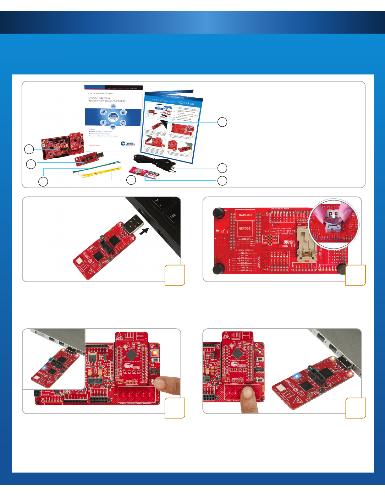
• Insert the 3-V coin cell (included with the kit)
into the coin cell holder on the rear side of
the baseboard
• Connect the dongle to your computer's USB port.
This demo does not require installing the drivers
for Windows 8 or earlier versions. Refer to Kit
Guide
for Windows 8.1 or later
• Press the button SW2 on both the dongle and the
baseboard. The red LED on the baseboard and
the blue LED on the dongle will stay on for three
seconds before turning off, indicating a Bluetooth
low energy connection between the two boards
1
• Move your nger over the CapSense® slider on
the baseboard to control the brightness of the
blue LED on the dongle
2
3 4
1
2
3
4
5
7
6
1 BLE Pioneer Baseboard preloaded with
CY8CKIT-143A PSoC® 4 BLE 256KB Module
2 CY5677 CySmart BLE 4.2 USB Dongle
(BLE Dongle)
3 Two proximity sensor wires (5 inches each)
4 Four Jumper Wires (4 inches each)
5 Coin cell (3V CR2032)
6 USB Standard-A to Mini-B cable
7 Quick Start Guide (this document)
Page 2
CY8CKIT-042-BLE-A QUICK START GUIDE
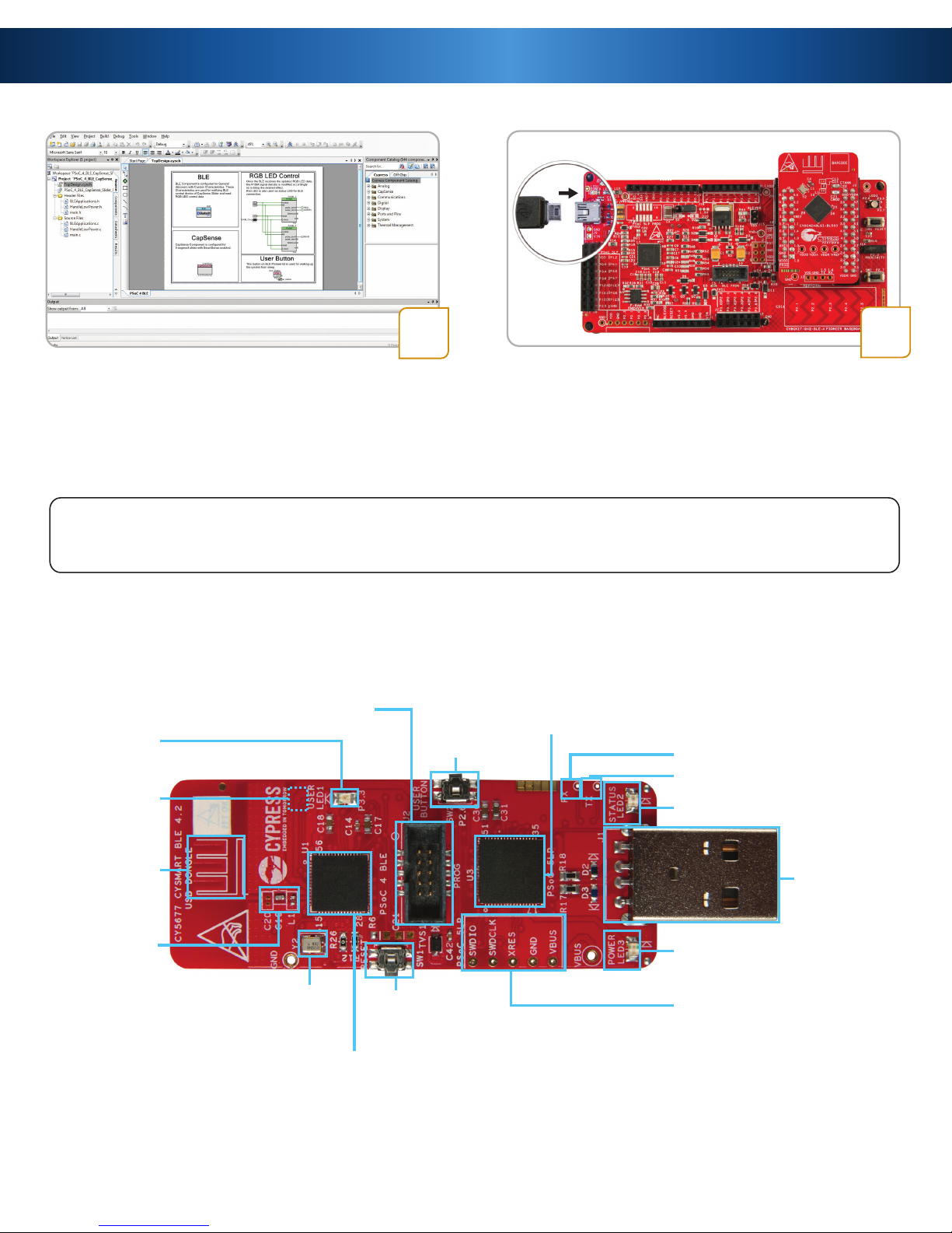
• Download and install the PSoC CreatorTM IDE,
BLE Pioneer Kit code examples, documents,
and hardware design les from
www.cypress.com/CY8CKIT-042-BLE-A
• To debug your PSoC Creator project, connect
the baseboard with the PSoC 4 BLE module to
your computer with a USB cable
• Refer to Chapter 4 of the Kit Guide for
additional information on code examples
5
Note: If you are evaluating this demo near another BLE Pioneer Kit that is advertising (when using the default
out-of-box rmware), the dongle may connect to the other baseboard instead. In this case, press the reset button
(SW1) on both the dongle and baseboard of your kit, then repeat step 3 to retry connection between the two
Feature List and Pinout Description for CySmart USB Dongle
PSoC 4 BLE
reset button
CY8C4248LQI-BL583
PSoC 4 BLE device
PSoC 5LP
programming test points
CY8C5868LTI-LP039
PSoC 5LP programmer
and debugger
User button
Power LED
USB plug
Status LED
P1_4 (PSoC 4 BLE)
P1_5 (PSoC 4 BLE)
Wiggle
antenna
Antenna
matching
network
(AMN)
24-MHz crystal
User LED
PSoC 4 BLE external programming header
32.768-kHz
crystal
(bottom side)
6
Page 3

GND VDDA
P3_6 P3_7
P3_4 P3_5
P3_2 P3_3
P3_0 P3_1
P4_0 P5_1
P4_1 P5_0
P2_6 P2_7
P2_4 P2_5
P2_2 P2_3
P2_0 P2_1
VDDR GND
P0_1 P0_0
P0_3 P0_2
P0_5 P0_4
P1_0 VREF
P1_2 P1_1
P0_6 P1_4
P0_7 P1_3
XRES P1_5
GND P1_7
VDDD P1_6
VDD
GND
P1_4
P1_5
Wiggle antenna
32.768-kHz crystal (bottom side)
Cmod
Ctank
Antenna matching network (AMN)
CY8C4248LQI-BL583
PSoC 4 BLE device
PSoC 4 BLE module header (J2)
PSoC 4 BLE module header (J1)
4-pin UART header
SAR bypass capacitor (bottom side)
24-MHz crystal
CY8CKIT-042-BLE-A QUICK START GUIDE
Feature List and Pinout Description for PSoC 4 BLE 256KB Module
PSoC 4 BLE - A single chip solution with a 48-MHz ARM® Cortex®-M0, BLE 4.2 radio, CapSense, programmable analog
(12-bit ADC, 2 Current DACs, 2 Low Power Comparators, 4 Low Power Opamps) and programmable digital peripherals
(4 Timer/Counter/PWMs, 4 Universal Digital Blocks, 2 Serial Communication Blocks)
Page 4

© 2016 - 2018 Cypress Semiconductor Corporation. All rights reserved.
All trademarks or registered trademarks referenced herein are the properties of their respective owners.
Doc.#: 002-11473 Rev.*C
ArduinoTM Pin Denition
BLE Pioneer Baseboard
For the latest information about this kit and to download kit software and hardware les,
visit www.cypress.com/CY8CKIT-042-BLE-A
P3_5/SCL
P3_4/SDA
VREF/AREF
GND/GND
P0_3/D13
P0_1/D12
P0_0/D11
P0_2/D10
P0_4/D9
P0_5/D8
P1_0/D7
P1_1/D6
P1_2/D5
P1_3/D4
P1_7/D3
P1_6/D2
P1_5/D1
P1_4/D0
GND
P5LP12_5
P5LP3_0
P5LP12_7
P5LP3_7
P5LP3_5
P5LP0_1
P5LP1_2
P5LP12_0
P5LP2_5
VDD
P5LP0_0
P5LP3_4
P5LP3_6
P5LP12_6
P5LP12_1
NC
IOREF/BLE_VDD
RESET/RESET
3.3 V/V 3.3
5 V/V 5.0
GND/GND
GND/GND
Vin/VIN
A0/P3_0
A1/P3_1
A2/P3_2
A3/P3_3
A4/P3_4
A5/P3_5
P2_5
P2_4
P2_3
P2_2
P2_1
P2_0
1
1 RGB LED
2 BLE device reset button
3 CapSense proximity header
4 User button
5 CapSense slider
6 Arduino compatible I/O
Headers (J2/J3/J4)
7 Arduino-compatible
power header (J1)
8 Digilent
®
PmodTM compatible I/O
header (J5)
9 Cypress F-RAM 1 Mb
(FM24V10-G)
10 PSoC 5LP
I/O header (J8)
11 PSoC 5LP programmer
and debugger
(CY8C5868LTI-LP039)
12 Coin cell holder
(bottom side)
13 USB connector (J13)
14 Power LED and Status LED
15 System power supply
jumper (J16) - LDO
1.9 V~5 V
16 BLE power supply jumper /
current measurement (J15)
17 BLE module headers
(J10/J11)
2
3
4
5
6789
10
11
12
13
14
15 6 16 17
Feature List and Pinout Description for BLE Pioneer Baseboard
P2_0
CY8CKIT-042-BLE-A QUICK START GUIDE
BLUETOOTH® LOW ENERGY PIONEER KIT
 Loading...