

Cypress CY8CKIT-040 PSoC 4000 Pioneer Kit Manual

CY8CKIT-040
PSoC® 4000 Pioneer Kit Guide
Doc. # 001-91316 Rev. *F
Cypress Semiconductor
198 Champion Court
San Jose, CA 95134-1709
www.cypress.com

Copyrights
Copyrights
© Cypress Semiconductor Corporation, 2014-2018. This document is the property of Cypress Semiconductor Corporation
and its subsidiaries, including Spansion LLC (“Cypress”). This document, including any software or firmware included or referenced in this document (“Software”), is owned by Cypress under the intellectual property laws and treaties of the United
States and other countries worldwide. Cypress reserves all rights under such laws and treaties and does not, except as specifically stated in this paragraph, grant any license under its patents, copyrights, trademarks, or other intellectual property
rights. If the Software is not accompanied by a license agreement and you do not otherwise have a written agreement with
Cypress governing the use of the Software, then Cypress hereby grants you a personal, non-exclusive, nontransferable
license (without the right to sublicense) (1) under its copyright rights in the Software (a) for Software provided in source code
form, to modify and reproduce the Software solely for use with Cypress hardware products, only internally within your organization, and (b) to distribute the Software in binary code form externally to end users (either directly or indirectly through
resellers and distributors), solely for use on Cypress hardware product units, and (2) under those claims of Cypress’s patents
that are infringed by the Software (as provided by Cypress, unmodified) to make, use, distribute, and import the Software
solely for use with Cypress hardware products. Any other use, reproduction, modification, translation, or compilation of the
Software is prohibited.
TO THE EXTENT PERMITTED BY APPLICABLE LAW, CYPRESS MAKES NO WARRANTY OF ANY KIND, EXPRESS OR
IMPLIED, WITH REGARD TO THIS DOCUMENT OR ANY SOFTWARE OR ACCOMPANYING HARDWARE, INCLUDING,
BUT NOT LIMITED TO, THE IMPLIED WARRANTIES OF MERCHANTABILITY AND FITNESS FOR A PARTICULAR PURPOSE. No computing device can be absolutely secure. Therefore, despite security measures implemented in Cypress hardware or software products, Cypress does not assume any liability arising out of any security breach, such as unauthorized
access to or use of a Cypress product. In addition, the products described in these materials may contain design defects or
errors known as errata which may cause the product to deviate from published specifications. To the extent permitted by
applicable law, Cypress reserves the right to make changes to this document without further notice. Cypress does not
assume any liability arising out of the application or use of any product or circuit described in this document. Any information
provided in this document, including any sample design information or programming code, is provided only for reference purposes. It is the responsibility of the user of this document to properly design, program, and test the functionality and safety of
any application made of this information and any resulting product. Cypress products are not designed, intended, or authorized for use as critical components in systems designed or intended for the operation of weapons, weapons systems, nuclear
installations, life-support devices or systems, other medical devices or systems (including resuscitation equipment and surgical implants), pollution control or hazardous substances management, or other uses where the failure of the device or system
could cause personal injury, death, or property damage (“Unintended Uses”). A critical component is any component of a
device or system whose failure to perform can be reasonably expected to cause the failure of the device or system, or to
affect its safety or effectiveness. Cypress is not liable, in whole or in part, and you shall and hereby do release Cypress from
any claim, damage, or other liability arising from or related to all Unintended Uses of Cypress products. You shall indemnify
and hold Cypress harmless from and against all claims, costs, damages, and other liabilities, including claims for personal
injury or death, arising from or related to any Unintended Uses
Cypress, the Cypress logo, Spansion, the Spansion logo, and combinations thereof, WICED, PSoC, CapSense, EZ-USB, FRAM, and Traveo are trademarks or registered trademarks of Cypress in the United States and other countries. For a more
complete list of Cypress trademarks, visit cypress.com. Other names and brands may be claimed as property of their respective owners.
of Cypress products.
CY8CKIT-040 PSoC
®
4000 Pioneer Kit Guide, Doc. # 001-91316 Rev. *F 2

Contents
Safety Information 5
1. Introduction 7
1.1 Kit Contents .................................................................................................................7
1.2 PSoC Creator ..............................................................................................................9
1.3 Getting Started...........................................................................................................13
1.4 Additional Learning Resources..................................................................................13
1.5 Technical Support......................................................................................................14
1.6 Documentation Conventions......................................................................................14
2. Software Installation 15
2.1 Before You Begin.......................................................................................................15
2.2 Install Software ..........................................................................................................15
2.3 Install Hardware.........................................................................................................17
2.4 Uninstall Software......................................................................................................18
1.2.1 PSoC Creator Code Examples ......................................................................10
1.2.2 Kit Code Example .......................................................................................... 11
1.2.3 PSoC Creator Help ........................................................................................12
3. Kit Operation 19
3.1 Kit Overview...............................................................................................................19
3.2 Kit USB Connection ...................................................................................................21
3.3 Programming and Debugging PSoC 4000 ................................................................22
3.3.1 Using the Onboard PSoC 5LP Programmer and Debugger ..........................22
3.3.2 Using the CY8CKIT-002 MiniProg3 Programmer and Debugger...................23
3.4 USB-I2C Bridge .........................................................................................................25
3.5 USB-UART Bridge .....................................................................................................26
3.6 Updating the Onboard Programmer Firmware ..........................................................27
4. Hardware 29
4.1 Board Details .............................................................................................................29
4.2 Block Diagram ...........................................................................................................32
4.3 Kit Component Details ...............................................................................................33
4.3.1 CY8CKIT-040 Baseboard Components .........................................................33
4.3.2 CY8CKIT-040 CapSense Trackpad Shield Board..........................................47
CY8CKIT-040 PSoC® 4000 Pioneer Kit Guide, Doc. # 001-91316 Rev. *F 3

Contents
5. Code Examples 49
5.1 Overview....................................................................................................................49
5.1.1 Programming the Example Projects...............................................................49
5.2 Project: Blinking LED .................................................................................................54
5.2.1 Project Overview ............................................................................................54
5.2.2 Project Description .........................................................................................55
5.2.3 Verify Output ..................................................................................................56
5.3 Project: CapSense Proximity and UART ...................................................................57
5.3.1 Project Overview ............................................................................................57
5.3.2 Project Description .........................................................................................58
5.3.3 Verify Output ..................................................................................................67
5.4 Project: CapSense Touchpad with I2C Tuner ...........................................................74
5.4.1 Project Overview ............................................................................................74
5.4.2 Project Description .........................................................................................76
5.4.3 Verify Output ..................................................................................................79
5.5 Project: Color Palette.................................................................................................84
5.5.1 Project Overview ............................................................................................84
5.5.2 Project Description .........................................................................................84
5.5.3 Verify Output ................................................................................................101
5.6 ADC in PSoC 4000 ..................................................................................................102
5.6.1 Using PSoC Creator Code Example: ADC_VoltageInput.............................102
6. Advanced Topics 105
6.1 Using PSoC 5LP as a USB-I2C Bridge ...................................................................105
6.2 Using FM24W256 F-RAM........................................................................................113
6.2.1 Address Selection ........................................................................................113
6.2.2 Write/Read Operation .................................................................................. 114
6.2.3 Example Firmware .......................................................................................115
6.3 Using PSoC 5LP as a USB-UART Bridge ...............................................................118
6.4 Developing Applications for PSoC 5LP ...................................................................130
6.4.1 Building a Bootloadable Project for PSoC 5LP ............................................131
6.4.2 Building a Normal Project for PSoC 5LP......................................................139
6.5 PSoC 5LP Factory Program Restore Instructions ...................................................141
6.5.1 PSoC 5LP Programmed with a Bootloadable Application............................141
6.5.2 PSoC 5LP Programmed with a Standard Application ..................................147
6.6 Using µC/Probe Tool ...............................................................................................149
A. Appendix 158
A.1 CY8CKIT-040 Schematics.......................................................................................158
A.2 Pin Assignment Table..............................................................................................163
A.3 Program and Debug Headers..................................................................................165
A.4 Use of Zero-ohm Resistors and No Load ................................................................166
A.5 KitProg Status LED States.......................................................................................167
A.6 Bill of Materials ........................................................................................................168
A.7 Trackpad/Touchpad Sticker Details .........................................................................171
A.8 Regulatory Compliance Information ........................................................................171
A.9 Migrating Projects Across Different Pioneer Series Kits ..........................................172
Revision History 176
Document Revision History ...............................................................................................176
CY8CKIT-040 PSoC® 4000 Pioneer Kit Guide, Doc. # 001-91316 Rev. *F 4
Safety Information
The CY8CKIT-040 contains electrostatic discharge (ESD) sensitive
devices. Electrostatic charges readily accumulate on the human body
and any equipment, and can discharge without detection. Permanent
damage may occur to devices subjected to high-energy discharges.
Proper ESD precautions are recommended to avoid performance
degradation or loss of functionality. Store unused CY8CKIT-040
boards in the protective shipping package.
End-of-Life/Product Recycling
The end of life for this kit is five years from the date of manufacture
mentioned on the back of the box. Contact your nearest recycler to
discard the kit.
Regulatory Compliance
The CY8CKIT-040 PSoC® 4000 Pioneer Kit is intended for use as a development platform for
hardware or software in a laboratory environment. The board is an open system design, which does
not include a shielded enclosure. For this reason, the board may cause interference to other
electrical or electronic devices in close proximity. In a domestic environment, this product may cause
radio interference. In such cases, the user may be required to take adequate preventive measures.
Also, this board should not be used near any medical equipment or RF devices.
Attaching additional wiring to this product or modifying the product operation from the factory default
may affect its performance and cause interference with other apparatus in the immediate vicinity. If
such interference is detected, suitable mitigating measures should be taken.
The CY8CKIT-040 as shipped from the factory has been verified to meet with requirements of CE as
a Class A product.
CY8CKIT-040 PSoC® 4000 Pioneer Kit Guide, Doc. # 001-91316 Rev. *F 5

Safety Information
General Safety Instructions
ESD Protection
ESD can damage boards and associated components. Cypress recommends that the user perform
procedures only at an ESD workstation. If an ESD workstation is not available, use appropriate ESD
protection by wearing an antistatic wrist strap attached to the chassis ground (any unpainted metal
surface) on the board when handling parts.
Handling Boards
CY8CKIT-040 boards are sensitive to ESD. Hold the board only by its edges. After removing the
board from its box, place it on a grounded, static free surface. Use a conductive foam pad if
available. Do not slide the board over any surface.
CY8CKIT-040 PSoC® 4000 Pioneer Kit Guide, Doc. # 001-91316 Rev. *F 6

1. Introduction
Thank you for your interest in the PSoC® 4000 Pioneer Kit. The kit is designed as an easy-to-use
and inexpensive development kit, highlighting the unique flexibility of the PSoC 4000 architecture.
Designed for flexibility, this kit offers footprint compatibility with several third-party Arduino™ shields.
In addition, the board features an RGB LED, integrated USB programmer/debugger, a program/
debug header, USB-UART/I
Trackpad shield. This kit supports either 5 V or 3.3 V as power supply voltages.
The PSoC 4000 Pioneer Kit is based on the PSoC 4000 device family, delivering a programmable
platform for a wide range of embedded applications. The PSoC 4000 is the smallest member of the
PSoC 4 platform with support for CapSense, timer, counter, and pulse width modulator (TCPWM),
2
I
C master or slave, and up to 20 GPIOs. PSoC 4000 is a cost-optimized, entry-level PSoC 4 device
targeted as socket replacements for obsolete and/or proprietary 8-bit and 16-bit MCUs. PSoC 4000
with its ARM Cortex-M0 core provides 32 programmable peripherals including CapSense.
1.1 Kit Contents
2
C bridges, a proximity header, and an Arduino-compatible CapSense
®
The PSoC 4000 Pioneer Kit contains the following (see Figure 1-1):
■ PSoC 4000 Pioneer Kit board
■ Trackpad shield board with a color palette sticker
■ Quick start guide
■ USB Standard-A to Mini-B cable
■ Six jumper wires
Note: Trackpad and Touchpad denote the same in the context of this document and can be used
interchangeably.
CY8CKIT-040 PSoC® 4000 Pioneer Kit Guide, Doc. # 001-91316 Rev. *F 7
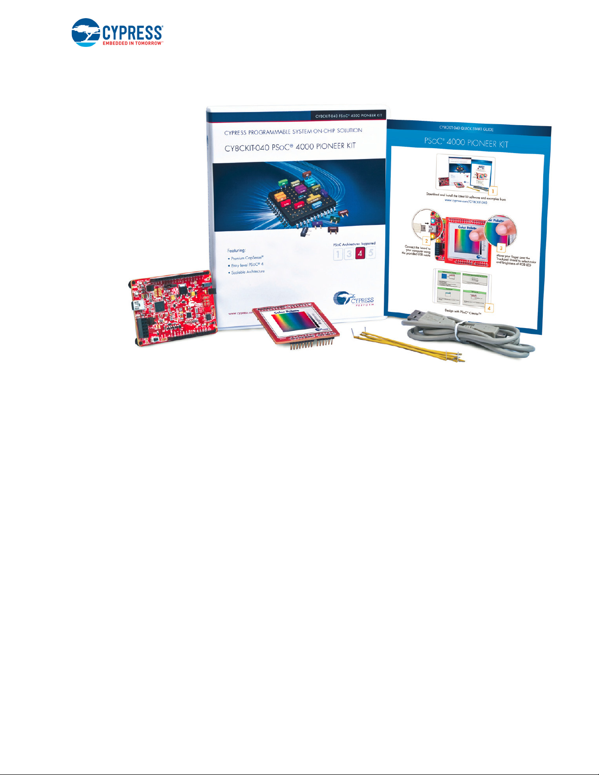
Figure 1-1. Kit Contents
Introduction
Inspect the contents of the kit; if you find any part missing, contact your nearest Cypress sales office
for help: www.cypress.com/go/support.
Download the latest version of the kit setup file from www.cypress.com/CY8CKIT-040.
CY8CKIT-040 PSoC® 4000 Pioneer Kit Guide, Doc. # 001-91316 Rev. *F 8
1.2 PSoC Creator
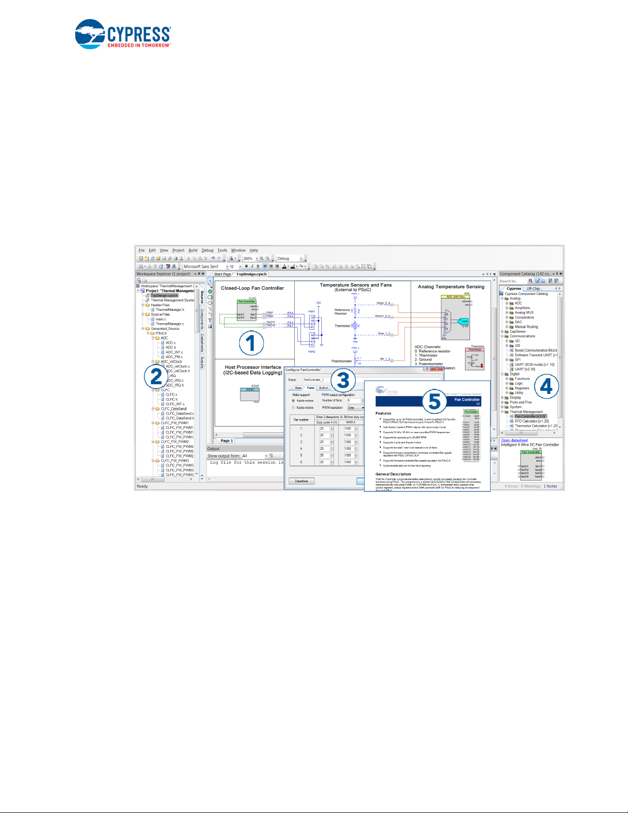
PSoC Creator™ is a state-of-the-art, easy-to-use integrated design environment (IDE). It introduces
revolutionary hardware and software co-design, powered by a library of preverified and
precharacterized PSoC Components. With PSoC Creator, you can:
1. Drag and drop Components to build your hardware system design in the main design workspace
2. Codesign your application firmware with the PSoC hardware
3. Configure Components using configuration tools
4. Explore the library of 100+ Components
5. Review Component datasheets
Figure 1-2. PSoC Creator Features
Introduction
PSoC Creator also enables you to tap into an entire tool ecosystem with integrated compiler chains
and production programming programmers for PSoC devices.
For more information, visit www.cypress.com/psoccreator. Visit PSoC Creator training page for video
tutorials on learning and using PSoC Creator.
CY8CKIT-040 PSoC® 4000 Pioneer Kit Guide, Doc. # 001-91316 Rev. *F 9
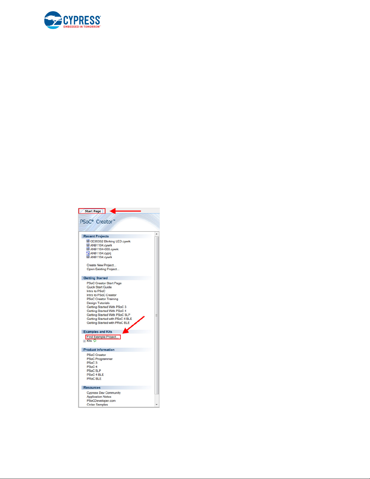
1.2.1 PSoC Creator Code Examples
PSoC Creator includes a large number of code examples. These examples are available from the
PSoC Creator Start Page, as Figure 1-3 shows.
Code examples can speed up your design process by starting you off with a complete design,
instead of a blank page. The code examples also show how PSoC Creator Components can be
used for various applications. Code examples and documentation are included, as shown in
Figure 1-4 on page 11.
In the Find Example Project dialog shown in Figure 1-4 on page 11, you have several options:
■ Filter for examples based on architecture or device family, that is, PSoC 3, PSoC 4, or
PSoC 5LP; project name; or keyword.
■ Select from the menu of examples offered based on the Filter Options.
■ Review the example project’s description (on the Documentation tab).
■ Review the code from the Sample Code tab. You can copy the code from this window and paste
to your project, which can help speed up code development.
■ Create a new project (and a new workspace if needed) based on the selection. This can speed
up your design process by starting you off with a complete, basic design. You can then adapt that
design to your application.
Figure 1-3. Code Examples in PSoC Creator
Introduction
CY8CKIT-040 PSoC® 4000 Pioneer Kit Guide, Doc. # 001-91316 Rev. *F 10
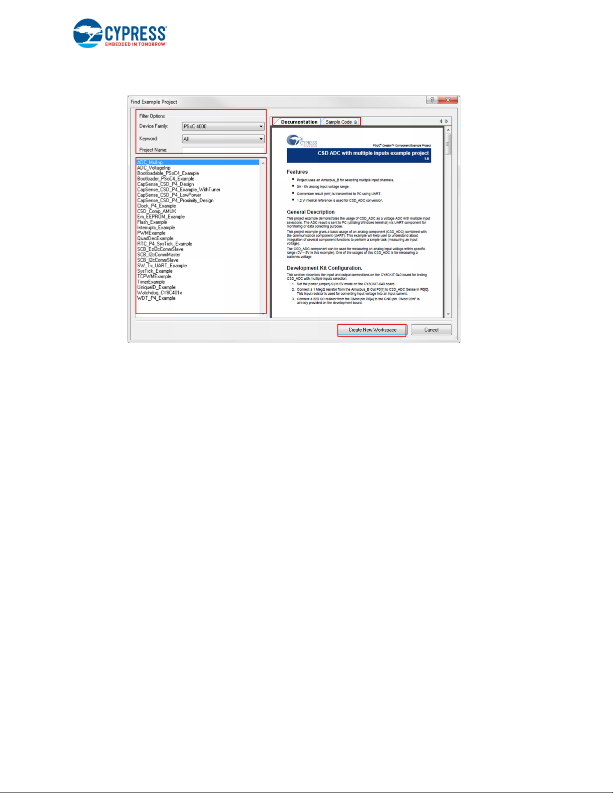
Figure 1-4. Code Example Projects with Sample Code
Introduction
1.2.2 Kit Code Example
In addition to the examples built into PSoC Creator, this kit includes a simple example, which can be
used to quickly evaluate the functionality of this kit. The example is described in the Code
Examples chapter on page 49. In addition, the chapter also includes a section explaining how to use
PSoC Creator code examples with the kit by taking one example.
CY8CKIT-040 PSoC® 4000 Pioneer Kit Guide, Doc. # 001-91316 Rev. *F 11
1.2.3 PSoC Creator Help
Visit the PSoC Creator home page to download the latest version of PSoC Creator. Then, launch
PSoC Creator and navigate to the following items:
■ Quick Start Guide: Choose Help > Documentation > Quick Start Guide. This guide gives you
the basics for developing PSoC Creator projects.
■ Simple Component example projects: Choose File > Example project.... These example
projects demonstrate how to configure and use PSoC Creator Components.
■ Starter designs: Choose File > New > Project > PSoC 4000 Starter Designs. These starter
designs demonstrate the unique features of PSoC 4.
■ System Reference Guide: Choose Help > System Reference Guides. This guide lists and
describes the system functions provided by PSoC Creator.
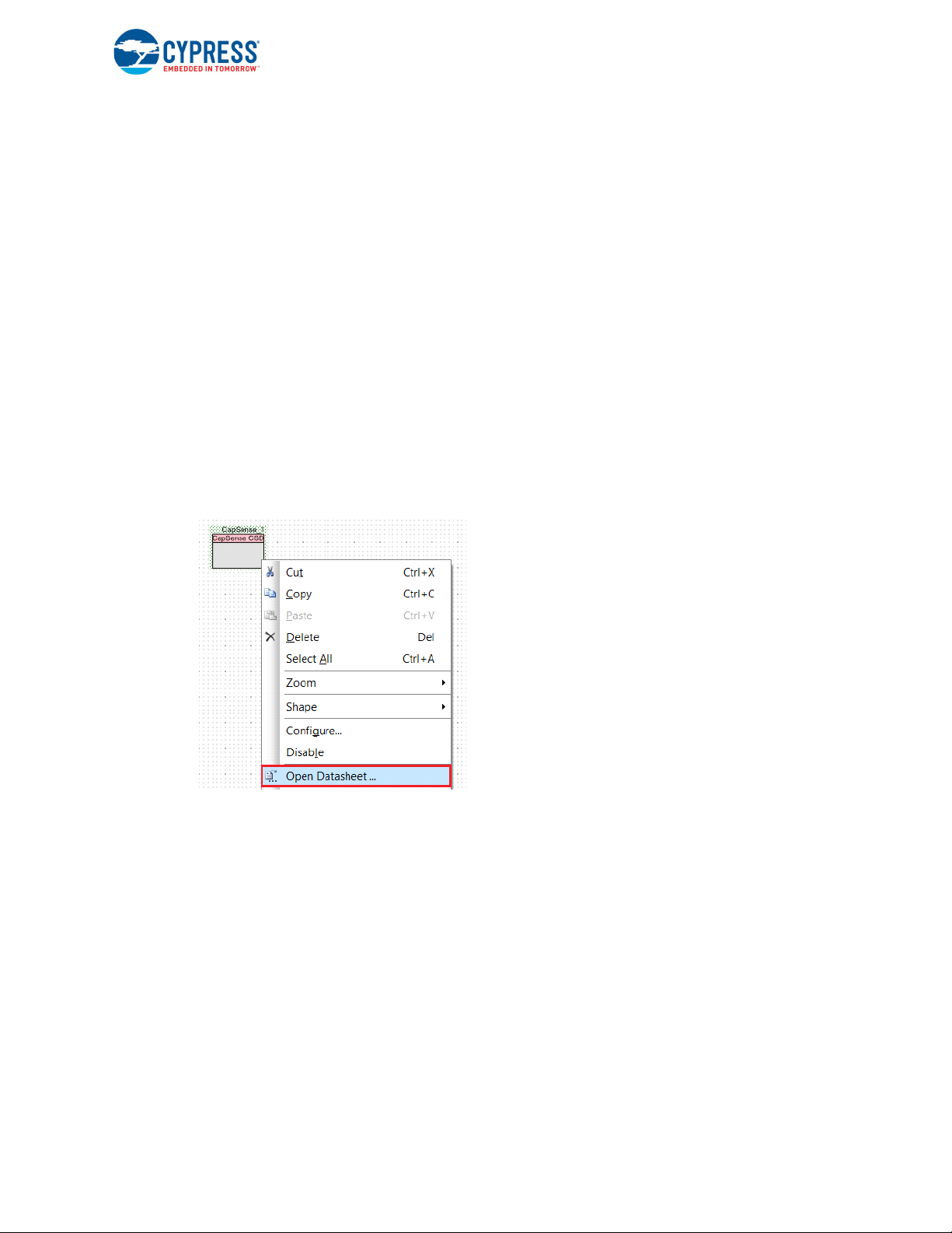
■ Component datasheets: Right-click a Component and select Open Datasheet, as shown in
Figure 1-5 on page 12. Visit the PSoC 4 Component Datasheets page for a list of all PSoC 4
Component datasheets.
■ Document Manager: PSoC Creator provides a document manager to help you to easily find and
review document resources. To open the document manager, choose the menu item Help >
Document Manager.
Figure 1-5. Opening Component Datasheet
Introduction
CY8CKIT-040 PSoC® 4000 Pioneer Kit Guide, Doc. # 001-91316 Rev. *F 12

1.3 Getting Started
This guide helps acquaint you with the PSoC 4000 Pioneer Kit.
■ The Software Installation chapter on page 15 describes the installation of the kit software.
■ The Kit Operation chapter on page 19 explains how to program the PSoC 4 with a programmer
and debugger, either the onboard PSoC 5LP or the external MiniProg3 (CY8CKIT-002).
■ The Hardware chapter on page 29 details the hardware operation.
■ The Code Examples chapter on page 49 describes the example projects that are provided with
the kit.
■ The Advanced Topics chapter on page 105 deals with topics such as building projects for
PSoC 5LP, using onboard F-RAM, USB-UART functionality, and USB-I
PSoC 5LP.
■ The Appendix on page 158 provides schematics, pin assignments, information on the use of
zero-ohm resistors, troubleshooting details, and the bill of materials (BOM).
1.4 Additional Learning Resources
Cypress provides a wealth of information at www.cypress.com to help you to select the right PSoC
device for your design, and to help you to quickly and effectively integrate the device into your
design. For a comprehensive list of resources, see KBA86521, How to Design with PSoC 3, PSoC 4,
and PSoC 5LP. The following is an abbreviated list for PSoC 4:
■ Overview: PSoC Portfolio and PSoC Roadmap
■ Product Selectors: PSoC 1, PSoC 3, PSoC 4, or PSoC 5LP. In addition, PSoC Creator includes a
device selection tool.
■ Datasheets: Describe and provide electrical specifications for the PSoC 4000 device family.
■ CapSense Design Guide: Learn how to design capacitive touch-sensing applications with the
PSoC 4 family of devices.
■ Application Notes and Code Examples: Cover a broad range of topics, from basic to advanced
level. Many of the application notes include code examples. Visit the PSoC 3/4/5 Code Examples
webpage for a list of all available PSoC Creator code examples. To access code examples from
within PSoC Creator, see PSoC Creator Code Examples on page 10.
■ Technical Reference Manuals (TRM): Provide detailed descriptions of the architecture and
registers in each PSoC 4 device family.
■ Development Kits:
❐ CY8CKIT-040, CY8CKIT-042, and CY8CKIT-044 are easy-to-use and inexpensive develop-
ment platforms. These kits include connectors for Arduino-compatible shields and Digilent
Pmod peripheral modules.
❐ CY8CKIT-049 and CY8CKIT-043 are very low-cost prototyping platforms for sampling PSoC 4
devices.
❐ The MiniProg3 kit provides an interface for flash programming and debug.
■ Knowledge Base Articles (KBA): Provide design and application tips from experts on using the
device.
■ PSoC Creator Training: Visit www.cypress.com/go/creatorstart/creatortraining for a
comprehensive list of video trainings on PSoC Creator.
■ Learning From Peers: Visit www.cypress.com/forums to meet enthusiastic PSoC developers
discussing the next generation embedded systems on Cypress Developer Community Forums.
2
C functionality of
Introduction
CY8CKIT-040 PSoC® 4000 Pioneer Kit Guide, Doc. # 001-91316 Rev. *F 13
1.5 Technical Support
If you have any questions, you can create a support request at the Cypress Technical Support page.
If you are in the United States, you can talk to our technical support team by calling our toll-free number: +1-800-541-4736. Select option 2 at the prompt. If you are outside United States, you can talk to
our technical support team by calling: +1 (408) 943-2600 Ext. 2.
You can also use the following support resources if you need quick assistance.
■ Self-help
■ Local Sales Office Locations
1.6 Documentation Conventions
Table 1-1. Document Conventions for Guides
Convention Usage
Courier New
Italics
[Bracketed, Bold]
File > Open
Bold
Times New Roman
Text in gray boxes Describes cautions or a unique functionality of the product.
Displays file locations, user-entered text, and source code:
C:\ ...cd\icc\
Displays file names and reference documentation:
Read about the sourcefile.hex file in the PSoC Creator User Guide.
Displays keyboard commands in procedures:
[Enter] or [Ctrl] [C]
Represents menu paths:
File > Open > New Project
Displays commands, menu paths, and icon names in procedures:
Click the File icon and then click Open.
Displays an equation:
2 + 2 = 4
Introduction
CY8CKIT-040 PSoC® 4000 Pioneer Kit Guide, Doc. # 001-91316 Rev. *F 14

2. Software Installation
This section describes the installation of the CY8CKIT-040 PSoC 4000 Pioneer Kit software and the
prerequisites.
2.1 Before You Begin
All Cypress software installations require administrator privileges. However, this is not the case for
installed software. Before you install the kit software, close any other Cypress software that is currently running.
2.2 Install Software
Follow these steps to install the CY8CKIT-040 PSoC 4000 Pioneer Kit software:
1. Download the CY8CKIT-040 software.
The CY8CKIT-040 software is available in three different formats for download:
a. CY8CKIT-040 Kit Only: This executable file installs only the kit contents, which include kit
code examples, hardware files, and user documents. This package can be used if all the
software prerequisites listed in step 5 are installed on your PC.
b. CY8CKIT-040 Kit Setup: This installation package contains all kit contents along with PSoC
Creator, Cypress Document Manager, and PSoC Programmer. However, it does not include
the Windows Installer or Microsoft .NET framework packages. If these packages are not on
your computer, the installer directs you to download and install them from the Internet.
c. CY8CKIT-040 CD ISO: This file is a complete package, stored in a CD-ROM image format
that you can use to create a CD or extract using ISO extraction programs, such as WinRAR.
The file can also be mounted like a virtual CD using virtual drive programs such as Virtual
CloneDrive or MagicISO. This file includes all the required software, utilities, drivers, hardware
files, and user documents.
CY8CKIT-040 PSoC® 4000 Pioneer Kit Guide, Doc. # 001-91316 Rev. *F 15
Software Installation
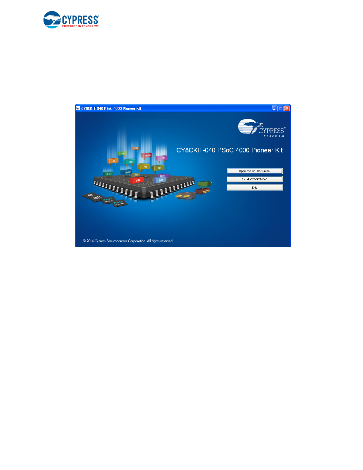
2. If you have downloaded the ISO file, mount it in a virtual drive. Extract the ISO contents if you do
not have a virtual drive to mount. Double-click cyautorun.exe in the root directory of the extracted
content or mounted ISO if 'Autorun from CD/DVD' is not enabledd in the PC. The installation window shown in Figure 2-1 will appear automatically. Note: If you are using the ‘Kit Setup’ or ‘Kit
Only’ file, then go to step 6 for installation.
3. Click Install CY8CKIT-040 to start the kit installation, as shown in Figure 2-1.
Figure 2-1. Kit Installer Startup Screen
4. Select the folder in which you want to install the CY8CKIT-040 kit-related files. Choose the direc-
tory and click Next.
5. When you click Next, the CY8CKIT-040 ISO installer automatically installs the required software,
if it is not present on your computer.
Following is the required software:
a. PSoC Creator 3.2 Service Pack 1 or later: Download the latest version from
www.cypress.com/psoccreator.
b. PSoC Programmer 3.23.1 or later: Download the latest version from
www.cypress.com/programmer.
c. Cypress Document Manager 1.0 Service Pack 1 or later: Download the latest version from
www.cypress.com/cypressdocumentmanager.
CY8CKIT-040 PSoC® 4000 Pioneer Kit Guide, Doc. # 001-91316 Rev. *F 16
Software Installation
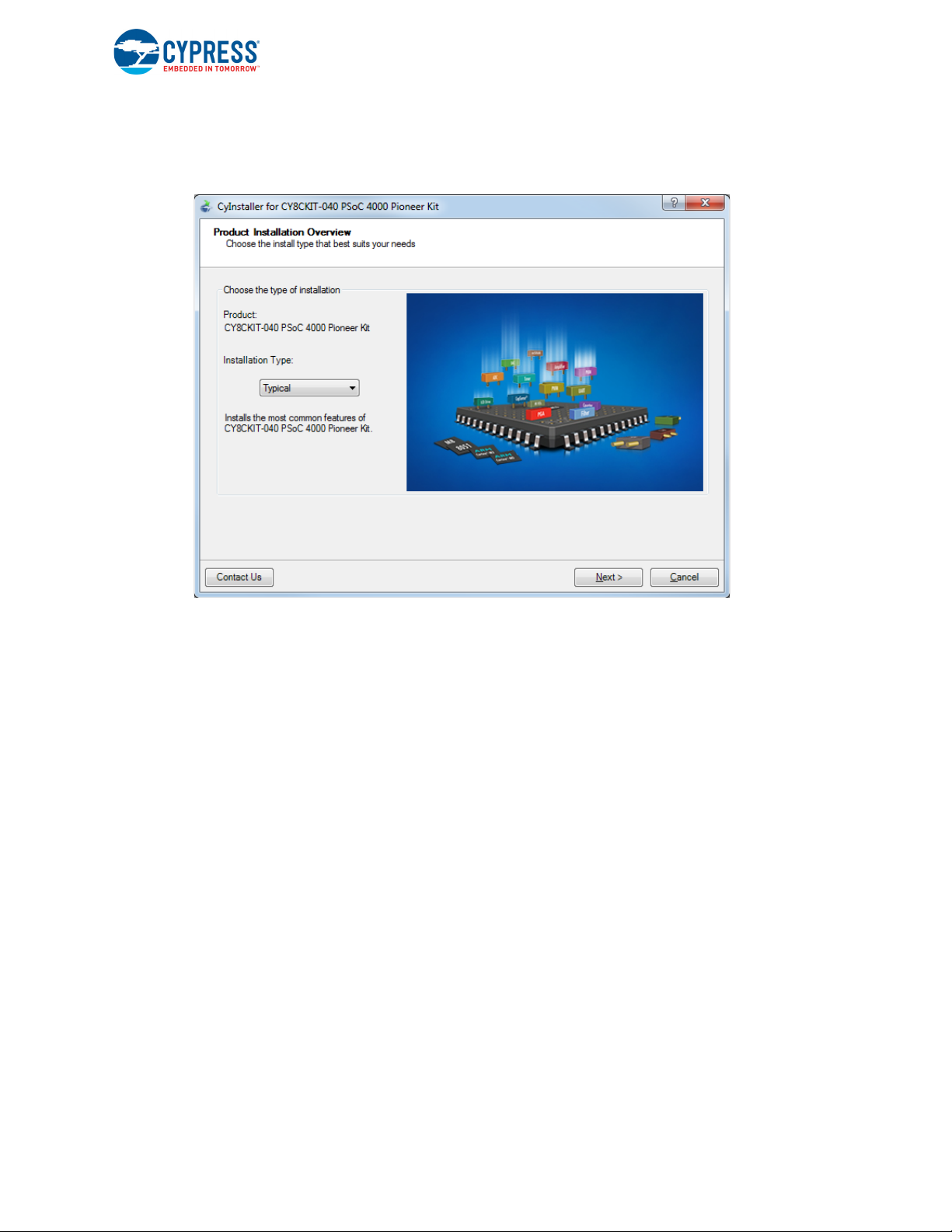
6. Choose the Typical/Custom/Complete installation type in the Product Installation Overview win-
dow, as shown in Figure 2-2. Click Next after you select the installation type.
Figure 2-2. Product Installation Overview Window
7. Read and Accept the End-User License Agreement and click Next to proceed with the
installation.
8. When the installation begins, a list of packages appears on the installation page. A green check
mark appears next to each package after successful installation.
9. Enter your contact information or select the check box Continue Without Contact Information.
Click Finish to complete the CY8CKIT-040 kit installation.
10.After the installation is complete, the kit contents are available at the following location:
<Install_Directory>\CY8CKIT-040 PSoC 4000 Pioneer Kit\<version>
Default location:
Windows 7 (64-bit):
C:\Program Files (x86)\Cypress\CY8CKIT-040 PSoC 4000 Pioneer Kit\<version>
Windows 7 (32-bit):
C:\Program Files\Cypress\CY8CKIT-040 PSoC 4000 Pioneer Kit\<version>
Note: For Windows 7/8/8.1 users, the installed files and the folder are read only. To change the
property, right-click the folder and choose Properties > Attributes; disable the Read-only check
box. Click Apply and OK to close the window.
2.3 Install Hardware
There is no additional hardware installation required for this kit.
CY8CKIT-040 PSoC® 4000 Pioneer Kit Guide, Doc. # 001-91316 Rev. *F 17

2.4 Uninstall Software
You can uninstall the CY8CKIT-040 PSoC 4000 Pioneer Kit software using one of the following
methods:
■ Go to Start > All Programs > Cypress > Cypress Update Manager > Cypress Update Man-
ager. Select the Uninstall button that corresponds to the kit software.
■ Go to Start > Control Panel > Programs and Features (or Add/Remove Programs for Win-
dows XP). Select the Uninstall/Change button that corresponds to the kit software.
Software Installation
CY8CKIT-040 PSoC® 4000 Pioneer Kit Guide, Doc. # 001-91316 Rev. *F 18
3. Kit Operation
ProximityHeader(J5)
PSoC4PowerSupply
Jumper(J13)
CypressF‐RAM256Kb
PSoC4000(24QFN)
PSoC4
ResetButton
PSoC5LP
I/OHeader(J8)
USBConnector
(J10)
PowerLED
(LED1)
RGBLED
(LED3)
LEDPower
Jumper(J14)
PSoC4External
ProgramandDebug
Header(J6)
PSoC5LP(68QFN)
ProgrammerandDebugger
SystemPowerSupply
Jumper(J9)
Arduino
CompatibleI/O
Header(J2)
StatusLED(LED2)
Arduino
CompatibleI/O
Header(J1)
Arduino
CompatibleI/O
Header(J4)
Arduino
CompatibleI/O
Header(J3)
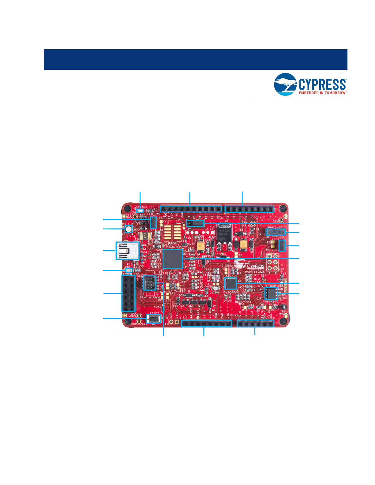
3.1 Kit Overview
The PSoC 4000 Pioneer Kit can be used to develop applications using the PSoC 4000 family of
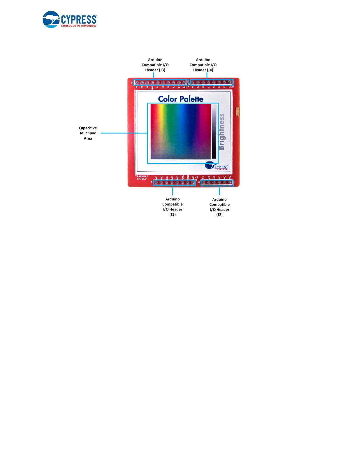
devices. The kit includes two boards – an Arduino-compatible baseboard and a CapSense-based
Trackpad shield board. Figure 3-1 is an image of the PSoC 4000 Pioneer Kit baseboard and shield
board with a markup of the onboard components.
Figure 3-1. CY8CKIT-040 Kit Details
CY8CKIT-040 PSoC® 4000 Pioneer Kit Guide, Doc. # 001-91316 Rev. *F 19
Kit Operation
CY8CKIT-040 PSoC® 4000 Pioneer Kit Guide, Doc. # 001-91316 Rev. *F 20
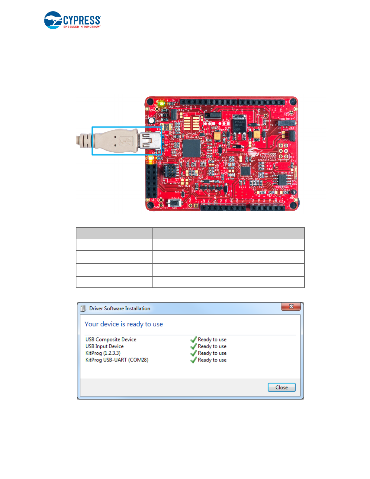
3.2 Kit USB Connection
The PSoC 4000 Pioneer Kit connects to the PC over a USB interface (see Figure 3-2). The kit enumerates as a composite device and three separate devices appear under the Device Manager in
the Windows operating system. See Tab l e 3-1, and Figure 3-3.
Figure 3-2. Kit USB Connection
Kit Operation
Table 3-1. PSoC 4000 Pioneer Kit in Device Manager After Enumeration
Port Description
USB Composite Device Composite device
USB Input Device
KitProg
KitProg USB-UART USB-UART bridge, which appears as the COM# port
2
USB-I
C bridge, KitProg command interface
USB-I2C bridge, programmer and debugger
Figure 3-3. KitProg Driver Installation Complete
CY8CKIT-040 PSoC® 4000 Pioneer Kit Guide, Doc. # 001-91316 Rev. *F 21
3.3 Programming and Debugging PSoC 4000
PSoC 5LP PSoC 4000
SWDCLK
SWDIO
Reset
P12[3]
P12[2]
P12[4]
P3[1]
P3[0]
XRES
Mini
USB
D-
D+
P15[6]
P15[7]
VDD
The kit allows programming and debugging of the PSoC 4 device in two modes:
■ 3.3.1 Using the Onboard PSoC 5LP Programmer and Debugger
■ 3.3.2 Using the CY8CKIT-002 MiniProg3 Programmer and Debugger
3.3.1 Using the Onboard PSoC 5LP Programmer and Debugger
The default programming interface for the kit is a USB-based, onboard programming interface.
Before trying to program the device, PSoC Creator and PSoC Programmer must be installed. See
Install Software on page 15 for information on installing the kit software.
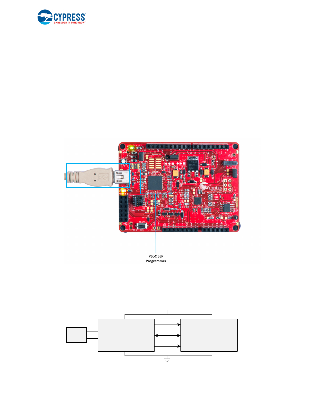
1. To program the device, plug the USB cable into the programming USB connector J10, as shown
in Figure 3-4. The kit will enumerate as a composite device. See Kit USB Connection on page 21
for details.
Figure 3-4. Connect USB Cable to J10
Kit Operation
2. The onboard PSoC 5LP uses serial wire debug (SWD) to program the PSoC 4 device. See
Figure 3-5.
Note: Figure 3-5 is provided only for reference, all connections are hardwired on the board itself.
Figure 3-5. SWD Programming of PSoC 4000 Using PSoC 5LP
CY8CKIT-040 PSoC® 4000 Pioneer Kit Guide, Doc. # 001-91316 Rev. *F 22
Kit Operation
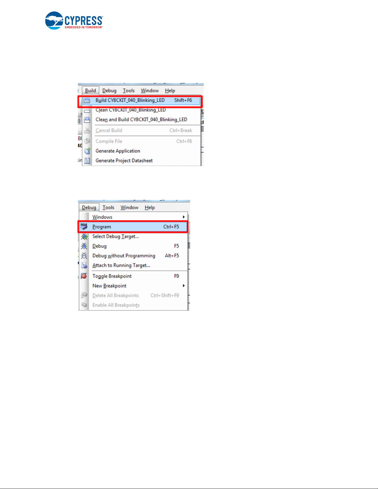
3. The kit’s onboard programmer will enumerate on the PC and in the software tools as KitProg.
Open an example project in PSoC Creator (such as Project: Blinking LED on page 54) and
initiate the build by choosing Build > Build Project or pressing [Shift] [F6]. See Figure 3-6.
Figure 3-6. Build Project in PSoC Creator
4. After the project is built without errors and warnings, choose Debug > Program or press
[Ctrl] [F5] to program the device. See Figure 3-7.
Figure 3-7. Program Device From PSoC Creator
The onboard programmer supports only the RESET programming mode. When using the onboard
programmer, the board can either be powered by the USB (VBUS) or by an external source such as
an Arduino shield (see Power Supply System on page 36). If the board is already powered from
another source, plugging in the USB programmer does not damage the board.
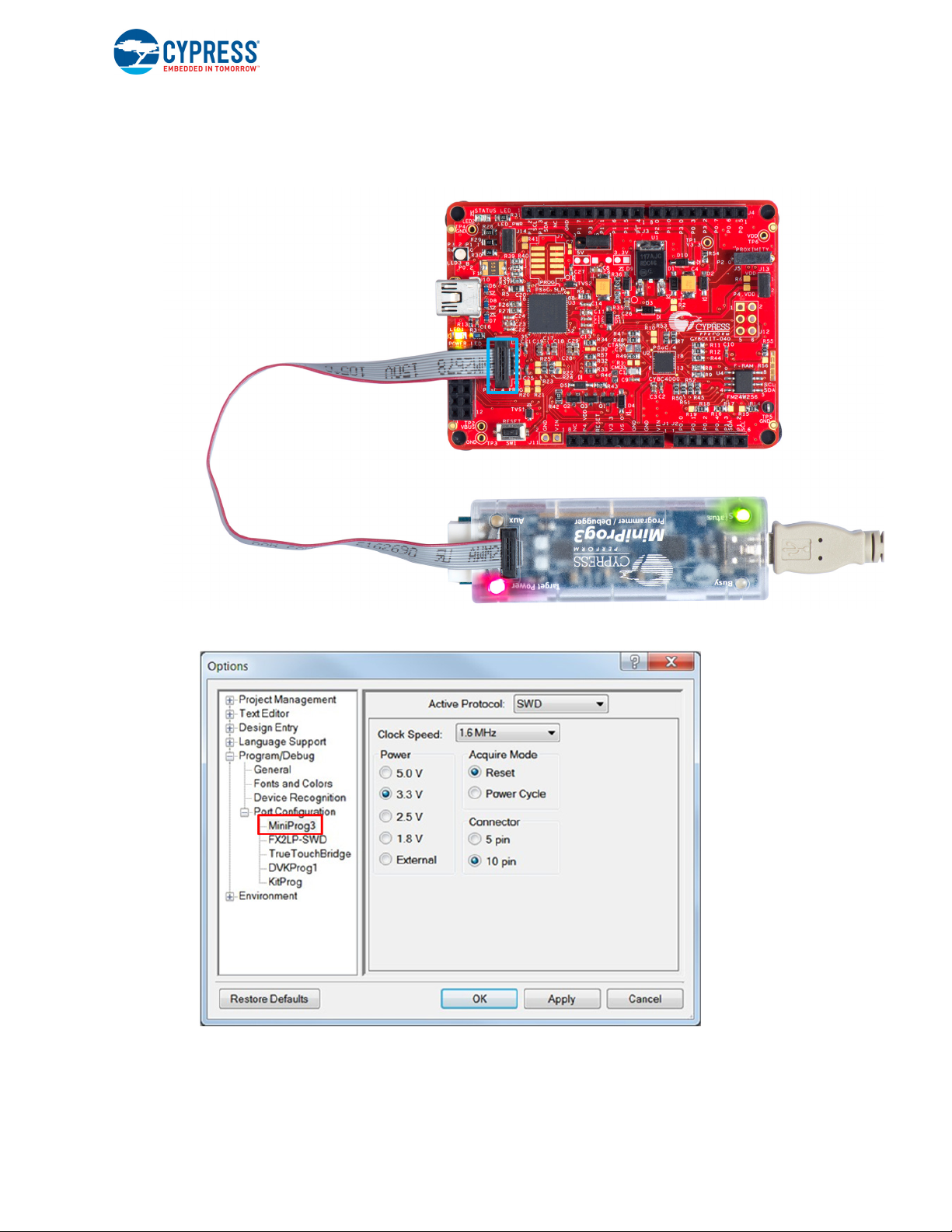
3.3.2 Using the CY8CKIT-002 MiniProg3 Programmer and Debugger
The PSoC 4 on the kit can also be programmed using a MiniProg3 (CY8CKIT-002). To use MiniProg3 for programming, use the J6 connector on the board, as shown in Figure 3-8. With MiniProg3,
programming is similar to the onboard programmer; however, it enumerates as MiniProg3 instead of
KitProg.
The board can also be powered from the MiniProg3. To do so, choose Tool > Options in PSoC Cre-
ator. In the Options window, expand Program/Debug > Port Configuration; click MiniProg3 and
select the settings shown in Figure 3-9. Choose Debug > Program to program and power the
board.
CY8CKIT-040 PSoC® 4000 Pioneer Kit Guide, Doc. # 001-91316 Rev. *F 23
Kit Operation
Note The CY8CKIT-002 MiniProg3 is not part of the PSoC 4000 Pioneer Kit contents. It can be purchased from the Cypress Online Store.
Figure 3-8. PSoC 4 Programming/Debug Using MiniProg3
Figure 3-9. MiniProg3 Configuration in PSoC Creator
Note: Ensure that both MiniProg3 (with or without power) on header J6 and KitProg are not connected to the onboard PSoC 4 at the same time. This will result in failed device acquisition from
both.
CY8CKIT-040 PSoC® 4000 Pioneer Kit Guide, Doc. # 001-91316 Rev. *F 24
3.4 USB-I2C Bridge
Kit Operation
The PSoC 5LP also functions as a USB-I2C bridge. The PSoC 4 communicates with the PSoC 5LP
using an I
2
C interface, and the PSoC 5LP transfers the data over the USB to the USB-I2C software
utility on the PC called the Bridge Control Panel (BCP).
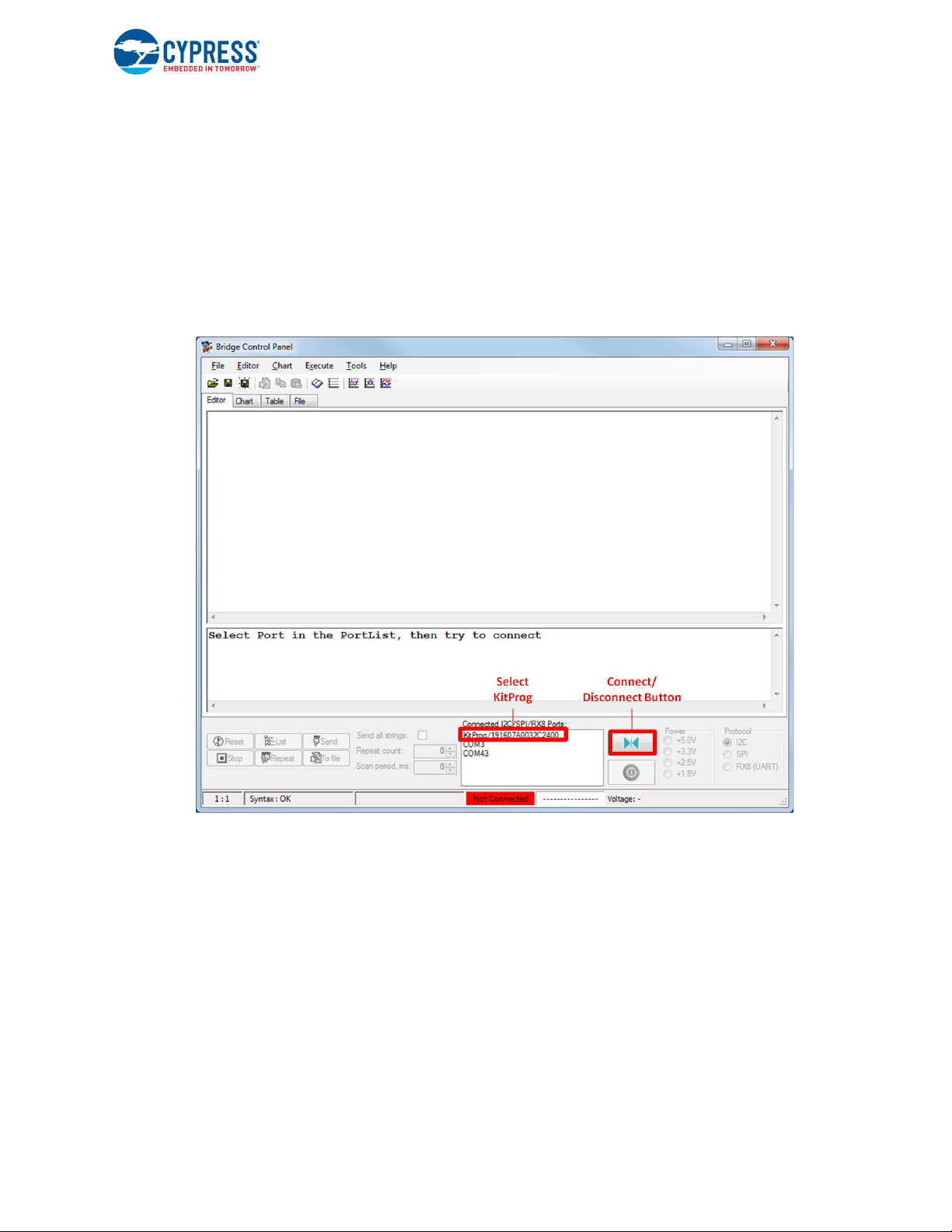
The BCP is available as part of the PSoC Programmer installation. This software can be used to
send and receive USB-I
header J10 on the PSoC 4000 Pioneer Kit, the KitProg USB-I
2
C data from the PSoC 5LP. When the USB Mini-B cable is connected to
2
C is available under Connected I2C/
SPI/RX8 Ports in the BCP, as shown in Figure 3-10.
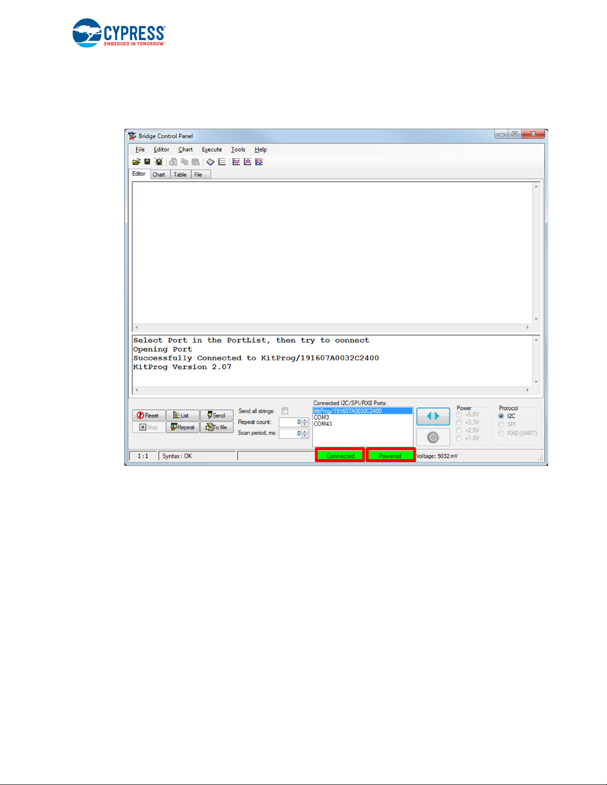
Figure 3-10. Bridge Control Panel
CY8CKIT-040 PSoC® 4000 Pioneer Kit Guide, Doc. # 001-91316 Rev. *F 25
Kit Operation
To use the USB-I2C functionality, select the KitProg USB-I2C in the BCP (Figure 3-10). On successful connection, the Connected and Powered status boxes turn green (Figure 3-11).
Figure 3-11. KitProg USB-I
2
C Connected in Bridge Control Panel
2
USB-I
C is implemented using the USB and I2C components of PSoC 5LP. The SCL (P12_0) and
SDA (P12_1) lines from the PSoC 5LP are connected to the SCL (P1_2) and SDA (P1_3) lines of
the PSoC 4 I
2
C. The USB-I2C bridge currently supports I2C speed of 50 kHz, 100 kHz, 400 kHz, and
1MHz.
See Using PSoC 5LP as a USB-I2C Bridge on page 105 for building a project that uses the USB-I
2
bridge functionality.
3.5 USB-UART Bridge
The onboard PSoC 5LP can also act as a USB-UART bridge to transfer and receive data from the
PSoC 4 device to the PC via the COM terminal software. When the USB Mini-B cable is connected
to J10 of the PSoC 4000 Pioneer Kit, a device named KitProg USB-UART is available under Ports
(COM & LPT) in the Device Manager. For more information about the USB-UART functionality, see
Using PSoC 5LP as a USB-UART Bridge on page 118.
CY8CKIT-040 PSoC® 4000 Pioneer Kit Guide, Doc. # 001-91316 Rev. *F 26
C
Kit Operation
To use the USB-UART functionality in the COM terminal software, select the corresponding COM
port as the communication port for transferring data to and from the COM terminal software.
The UART lines from PSoC 5LP are brought to the P12[6] (J8_9) and P12[7] (J8_10) pins of header
J8. This interface can be used to send or receive data from any design/device that has a UART by
connecting the pins on header J8 to the RX and TX pins available on the connecting device.
Note: The PSoC 4000 family that is featured in the kit board does not support a full-duplex UART; it
can support only a software-based UART transmit on any pin. On the board, P3[0] of the PSoC 4000
device is hardwired to the UART bridge's RX line through zero-ohm resistor R57.
Ta bl e 3 -2 lists the specifications supported by the USB-UART bridge.
Table 3-2. Specifications Supported by USB-UART Bridge
Parameter Supported Values
Baud rate 1200, 2400, 4800, 9600, 19200, 38400, 57600, and 115200
Data bits 8
Parity None
Stop bits 1
Flow control None
File transfer protocols
supported
Xmodem, 1K Xmodem, Ymodem, Kermit, and Zmodem (only speeds greater
than 2400 baud).
3.6 Updating the Onboard Programmer Firmware
The firmware of the onboard programmer and debugger (KitProg), PSoC 5LP, can be updated from
PSoC Programmer. When a new firmware is available or when the KitProg firmware is corrupt (see
KitProg Status LED States on page 167), PSoC Programmer displays a warning indicating that new
firmware is available.
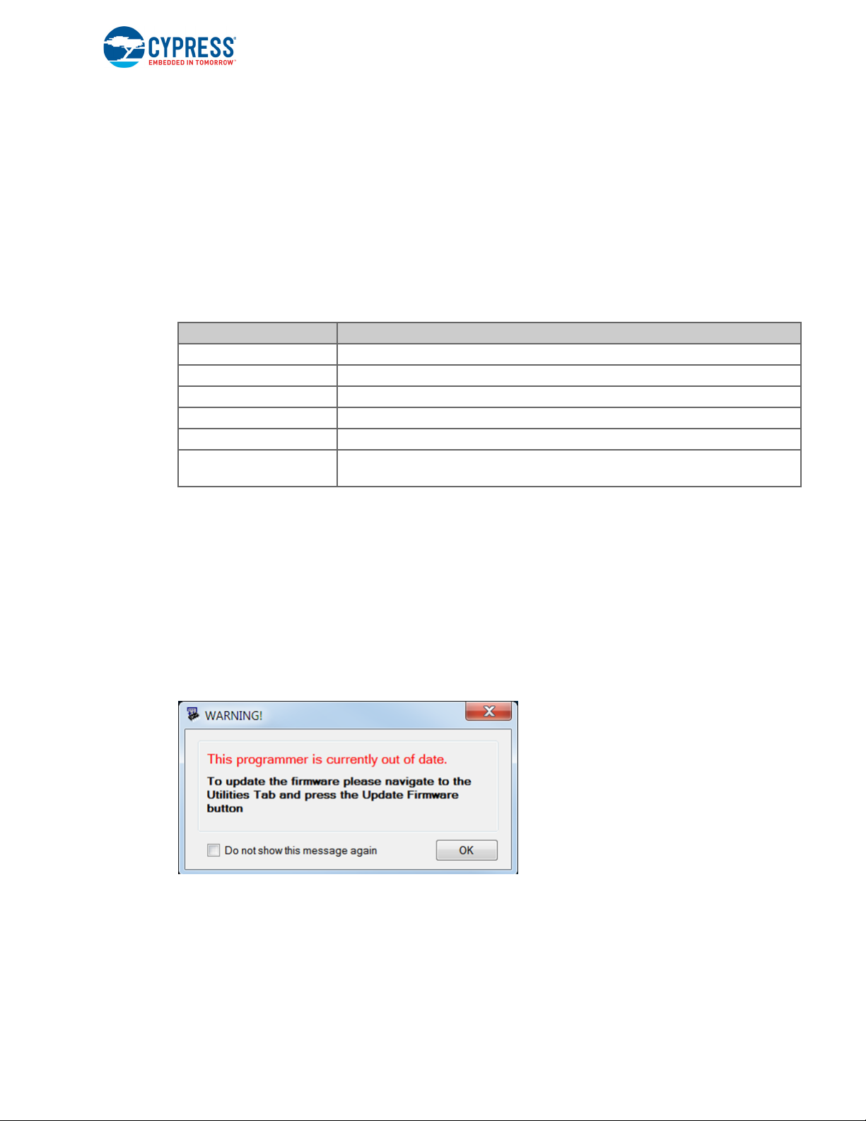
Open PSoC Programmer from Start > All Programs > Cypress > PSoC Programmer<version>.
When PSoC Programmer opens, a WARNING! window pops up saying that the programmer is currently out of date, as shown in Figure 3-12.
Figure 3-12. Firmware Update Warning
CY8CKIT-040 PSoC® 4000 Pioneer Kit Guide, Doc. # 001-91316 Rev. *F 27
Kit Operation
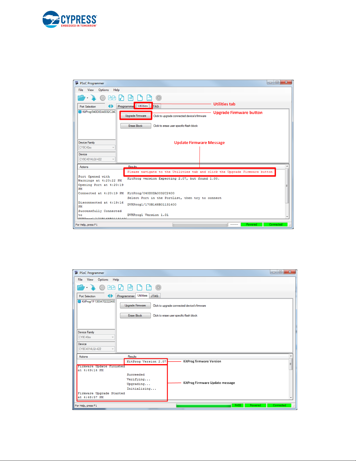
Click OK to close the window. On closing the warning window, the Actions and Results window displays Please navigate to the Utilities tab and click the Upgrade Firmware button, as shown in
Figure 3-13.
Figure 3-13. Upgrade Firmware Message in PSoC Programmer
Click the Utilities tab and then the Upgrade Firmware button. On successful upgrade, the Actions
and Results window displays the firmware update message with the KitProg version, as shown in
Figure 3-14.
Figure 3-14. Firmware Updated in PSoC Programmer
CY8CKIT-040 PSoC® 4000 Pioneer Kit Guide, Doc. # 001-91316 Rev. *F 28

4. Hardware
4.1 Board Details
The PSoC 4000 Pioneer Kit consists of the following blocks:
■ CY8CKIT-040 baseboard (see Figure 4-1) -
❐ PSoC 4 (4000 family)
❐ PSoC 5LP
❐ Power supply system
❐ Coin cell battery holder (BT1)
❐ Programming interfaces (J6, and J10)
❐ Arduino-compatible headers (J1, J2, J3, J4, and J12)
❐ PSoC 5LP GPIO header (J8)
❐ Proximity header (J5)
❐ Pioneer board LEDs
❐ Push button (Reset button)
❐ Cypress ferroelectric RAM (F-RAM)
■ CY8CKIT-040 CapSense Trackpad shield board (see Figure 4-2)
Note: Programming header J7 is not populated by default.
CY8CKIT-040 PSoC® 4000 Pioneer Kit Guide, Doc. # 001-91316 Rev. *F 29

Figure 4-1. CY8CKIT-040 - Baseboard Details
Coin Cell
Battery Hoder (BT1)
Hardware
CY8CKIT-040 PSoC® 4000 Pioneer Kit Guide, Doc. # 001-91316 Rev. *F 30
 Loading...