


al
b
C
C
CY7C66013
CY7C66113
Full-Speed USB (12 Mbps) Peripher
Controller with Integrated Hu
Full-Spee d U SB (12 Mbps) Peripheral Controller with Integrated Hub
Cypress Semiconductor Corporation • 198 Champion Court • San Jose, CA 95134-1709 • 408-943-2600
Document #: 38-08024 Rev. *B Revised January 2, 2006

C
C
CY7C66013
CY7C66113
TABLE OF CONTENTS
1.0 FEATURES .............. ........................................................................................................................6
2.0 FUNCTIONAL OVERVIEW .............................................................................................................7
2.1 GPIO .............. ............................................................................................................................7
2.2 DAC ......... ...................................................................................................................................7
2.3 Clock ..........................................................................................................................................7
2.4 Memory .............. ........................................................................................................................7
2.5 Power-on Reset, Watchdog, and Free-running Timer ..... ..........................................................7
2.6 I2C and HAPI Interface ..............................................................................................................7
2.7 Timer ... .......................................................................................................................................7
2.8 Interrupts ....................................................................................................................................8
2.9 USB ............................................................................................................................................8
3.0 PIN CONFIGURATIONS ....... ........................................................................................................10
4.0 PRODUCT SUMMARY TABLES ..................................................................................................14
4.1 Pin Assignments ......................................................................................................................14
4.2 I/O Register Summary ..............................................................................................................14
4.3 Instruction Set Summary ..........................................................................................................16
5.0 PROGRAMMING MODEL .............................................................................................................17
5.1 14-bit Program Counter (PC) .............. .....................................................................................17
5.1.1 Program Memory Or gan i za tion .......................................................................................... ..........18
5.2 8-bit Accumulator (A) ...............................................................................................................19
5.3 8-bit Temporary Register (X) ....................................................................................................19
5.4 8-bit Program Stack Pointer (PSP) ..... .....................................................................................19
5.4.1 Data Memory Organization ............................................................................................. .. .............19
5.5 8-bit Data Stack Pointer (DSP) ................................................................................................19
5.6 Address Modes ........................................................................................................................20
5.6.1 Data (Immediate ) ............................................................................................................................20
5.6.2 Direct ...... ........................................................................................................................................20
5.6.3 Indexed ..........................................................................................................................................20
6.0 CLOCKING ....................................................................................................................................20
7.0 RESET .......... .................................................................................................................................21
7.1 Power-on Reset .......................................................................................................................21
7.2 Watchdog Reset .......................................................................................................................21
8.0 SUSPEND MODE ..........................................................................................................................22
9.0 GENERAL-PURPOSE I/O (GPIO) PORTS ...................................................................................22
9.1 GPIO Configuration Port ..........................................................................................................23
9.2 GPIO Interrupt Enable Ports ....................................................................................................24
10.0 DAC PORT ..................................................................................................................................25
10.1 DAC Isink Registers ...............................................................................................................26
10.2 DAC Port Interrupts ................................................................................................................26
11.0 12-BIT FREE-RUNNING TIMER .................................................................................................27
2
12.0 I
13.0 I
C AND HAPI CONFIGURATION REGISTER ...........................................................................27
2
C-COMPATIBLE CONTROLLER .............................................................................................28
14.0 HARDWARE ASSISTED PARALLEL INTERFACE (HAPI) ....................................................... 30
15.0 PROCESSOR STATUS AND CONTROL REGISTER ................................................................31
Document #: 38-08024 Rev. *B Page 2 of 61

C
C
CY7C66013
CY7C66113
16.0 INTERRUPTS ..............................................................................................................................31
16.1 Interrupt Vectors .....................................................................................................................33
16.2 Interrupt Latency ....................................................................................................................34
16.3 USB Bus Reset Interrupt ........................................................................................................34
16.4 Timer Interrupt ........................................................................................................................ 34
16.5 USB Endpoint Interrupts ........................................................................................................34
16.6 USB Hub Interrupt ..................................................................................................................35
16.7 DAC Interrupt .........................................................................................................................35
16.8 GPIO/HAPI Interrupt ..............................................................................................................35
16.9 I
17.0 USB OVERVIEW .........................................................................................................................36
17.1 USB Serial Interface Engine ..................................................................................................36
17.2 USB Enumeration ..................................................................................................................36
18.0 USB HUB .....................................................................................................................................37
18.1 Connecting/Disconnecting a USB Device ..............................................................................37
18.2 Enabling/Disabling a USB Device ..........................................................................................38
18.3 Hub Downstream Ports Status and Control ...........................................................................39
18.4 Downstream Port Suspend and Resume ...............................................................................40
18.5 USB Upstream Port Status and Control .................................................................................41
19.0 USB SIE OPERATION ................................................................................................................42
2
C Interrupt ............................................................................................................................36
19.1 USB Device Addresses ..........................................................................................................42
19.2 USB Device Endpoints ...........................................................................................................42
19.3 USB Control Endpoint Mode Registers ..................................................................................43
19.4 USB Non-Control Endpoint Mode Registers ..........................................................................44
19.5 USB Endpoint Counter Registers ...........................................................................................44
19.6 Endpoint Mode/Count Registers Update and Locking Mechanism ........................................44
20.0 USB MODE TABLES ..................................................................................................................47
21.0 REGISTER SUMMARY ...............................................................................................................51
22.0 SAMPLE SCHEMATIC ................................................................................................................53
23.0 ABSOLUTE MAXIMUM RATINGS ..............................................................................................54
24.0 ELECTRICAL CHARACTERISTICS ...........................................................................................54
25.0 SWITCHING CHARACTERISTICS
26.0 ORDERING INFORMATION .......................................................................................................57
27.0 PACKAGE DIAGRAMS ...............................................................................................................58
28.0 QUAD FLAT PACKAGE NO LEADS (QFN) PACKAGE DESIGN NOTES ................................59
.............................................................................................55
Document #: 38-08024 Rev. *B Page 3 of 61

C
C
CY7C66013
CY7C66113
LIST OF FIGURES
Figure 3-1. CY7C66113C 56-pin QFN Pin Assignment .......................................................................11
Figure 3-2. CY7C66113C DIE .............................................................................................................. 12
Figure 5-1. Program Memory Space with Interrupt Vector Table .........................................................18
Figure 6-1. Clock Oscillator On-Chip Circuit ........................................................................................20
Figure 7-1. Watchdog Reset ................................................................................................................ 21
Figure 9-1. Block Diagram of a GPIO Pin ............................................................................................22
Figure 9-2. Port 0 Data ........................................................................................................................23
Figure 9-3. Port1 Data .........................................................................................................................23
Figure 9-4. Port 2 Data ........................................................................................................................23
Figure 9-5. Port 3 Data ........................................................................................................................23
Figure 9-6. GPIO Configuration Register .............................................................................................23
Figure 9-7. Port 0 Interrupt Enable .......................................................................................................24
Figure 9-8. Port 1 Interrupt Enable .......................................................................................................25
Figure 9-9. Port 2 Interrupt Enable .......................................................................................................25
Figure 9-10. Port 3 Interrupt Enable .....................................................................................................25
Figure 10-1. Block Diagram of a DAC Pin ............................................................................................25
Figure 10-2. DAC Port Data .................................................................................................................26
Figure 10-3. DAC Sink Register ...........................................................................................................26
Figure 10-4. DAC Port Interrupt Enable ...............................................................................................26
Figure 10-5. DAC Port Interrupt Polarity ..............................................................................................26
Figure 11-3. Timer Block Diagram .......................................................................................................27
Figure 11-1. Timer LSB Register .........................................................................................................27
Figure 11-2. Timer MSB Register ........................................................................................................27
Figure 12-1. HAPI/I
Figure 13-1. I
Figure 13-2. I
Figure 15-1. Processor Status and Control Register ...........................................................................31
Figure 16-1. Global Interrupt Enable Register .....................................................................................32
Figure 16-2. USB Endpoint Interrupt Enable Register .........................................................................32
Figure 16-3. Interrupt Controller Function Diagram .............................................................................33
Figure 16-4. GPIO Interrupt Structure ..................................................................................................35
Figure 18-1. Hub Ports Connect Status ...............................................................................................38
Figure 18-2. Hub Ports Speed .............................................................................................................38
Figure 18-3. Hub Ports Enable Register ..............................................................................................38
Figure 18-4. Hub Downstream Ports Control Register .........................................................................39
Figure 18-5. Hub Ports Force Low Register .........................................................................................39
Figure 18-6. Hub Ports SE0 Status Register .......................................................................................39
Figure 18-7. Hub Ports Data Register ..................................................................................................40
Figure 18-8. Hub Ports Suspend Register ........................................................................................... 40
Figure 18-9. Hub Ports Resume Status Register .................................................................................40
Figure 18-10. USB Status and Control Register ..................................................................................41
Figure 19-1. USB Device Address Registers .......................................................................................42
Figure 19-2. USB Endpoint 0 Mode Registers .....................................................................................43
Figure 19-3. USB Non-Control Endpoint Mode Registers ....................................................................44
Figure 19-4. USB Endpoint Counter Registers ....................................................................................44
Figure 19-5. Token/Data Packet Flow Diagram ...................................................................................46
Figure 22-1. Sample Schematic ...........................................................................................................53
Figure 25-1. Clock Timing ....................................................................................................................56
Figure 25-2. USB Data Signal Timing ..................................................................................................56
Figure 25-3. HAPI Read by External Interface from USB Microcontroller ............................................56
Figure 25-4. HAPI Write by External Device to USB Microcontroller ...................................................57
Figure 28-1. Cross-section of the Area Underneath the QFN Package ...............................................60
Figure 28-2. Plot of the Solder Mask (White Area) ..............................................................................60
2
2
2
C Configuration Register ......................................................................................27
C Data Register .............................................................................................................28
C Status and Control Register .......................................................................................28
Document #: 38-08024 Rev. *B Page 4 of 61

C
C
CY7C66013
CY7C66113
LIST OF TABLES
Table 3-1. Pad Coordinates in microns (0,0) to bond pad centers .......................................................13
Table 4-1. Pin Assignments .................................................................................................................14
Table 4-2. I/O Register Summary ........................................................................................................14
Table 4-3. Instruction Set Summary .....................................................................................................16
Table 9-1. GPIO Port Output Control Truth Table and Interrupt Polarity .............................................24
Table 12-1. HAPI Port Configuration .......................................................................................... ..........28
Table 12-2. I
Table 13-1. I
Table 14-1. Port 2 Pin and HAPI Configuration Bit Definitions ............................................................30
Table 16-1. Interrupt Vector Assignments .......... ..................................................................................34
Table 18-1. Control Bit Definition for Downstream Ports ................. ............................. .... ...................39
Table 18-2. Control Bit Definition for Upstream Port ............................................................................41
Table 19-1. Memory Allocation for Endpoints ......................................................................................42
Table 20-1. USB Register Mode Encoding ..........................................................................................47
Table 20-2. Decode T able for Table 20-3: “Details of Modes for Differing Traffic Conditio ns” ........... .48
Table 20-3. Details of Modes for Differing Traffic Conditions
2
C Port Configuration .................. .....................................................................................28
2
C Status and Control Register Bit Definitions .................................................................29
...............................................................49
Document #: 38-08024 Rev. *B Page 5 of 61

C
C
CY7C66013
CY7C66113
1.0 Features
• Full-speed USB peripheral microcontroller with an integrated USB hub
—Well-suited for USB compound devices such as a keyboard hub functi on
• 8-bit USB optimized microcontroller
—Harvard architecture
—6-MHz external clock source
—12-MHz internal CPU clock
—48-MHz internal Hub clock
• Internal memory
—256 bytes of RAM
—8 KB of PROM
2
• Integrated Master/Slave I
• Hardware-assisted Parallel Interface (HAPI) for data transfer to external devices
•I/O ports
—Three GPIO ports (Port 0 to 2) capable of sinking 8 mA per pin (typical)
—An additional GPIO port (Port 3) capable of sinking 12 mA per pin (typical) for high current requirements: LEDs
—Higher current drive achievable by connectin g multiple GPIO pins together to drive a common output
—Each GPIO port can be configured as inputs with inter nal pull-ups or open drain output s or traditional CMOS output s
—A Digital-to-Analog Conversion (DAC) port with programmable current sink output s is available on the CY7C661 13C
device
—Maskable interrupts on all I/O pins
• 12-bit free-runni ng ti me r wit h one microsecond clock ticks
• Watchdog T imer (WDT)
• Internal Power-on Reset (POR)
• USB Specification compliance
—Conforms to USB Specification, Version 1.1
—Conforms to USB HID Specification, Version 1.1
—Supports one or two device addresses with up to five user-configured endpoints
• Up to two 8-byte control endpoi nts
• Up to four 8-byte data endpoints
• Up to two 32-byte data end points
—Integrated USB transceivers
—Supports four downstream USB ports
—GPIO pins can provide individual power control outputs for each downstream USB port
—GPIO pins can provide indivi dual port over current inputs for each downstream USB port
• Improved output drive rs to reduce electromagnetic inte rference (EMI)
• Operating voltage from 4.0V–5.5V DC
• Operating temperature from 0°–70°C
• CY7C66013C available in 48-pin SSOP (-PVC) packages
• CY7C66113C available in 56-pin QFN or 56-pin SSOP (-PVC) packages
• Industry-standard programmer support
C-compatible controller (100 kHz) enabled through General-purpose I/O (GPIO) pins
Document #: 38-08024 Rev. *B Page 6 of 61

C
C
CY7C66013
CY7C66113
2.0 Functional Overview
The CY7C66013C and CY7C66113C are compound devices with a full-speed USB microcontroller in combination with a USB
hub. Each device is well-suited for combination peripheral functions with hubs, such as a keyboard hub function. The eight-bit
one-time-programm able microcontroller with a 12-Mbps USB Hub supports as many as four downstream ports.
2.1 GPIO
The CY7C66013C feat ures 29 G PIO pins t o support USB and other applic ations. The I /O pins are grouped into fo ur port s (P0[7:0 ],
P1[7:0], P2[7:0], P3[4:0]) where each port can be configured as inputs with internal pull-ups, open drain outputs, or traditional
CMOS outputs. Ports 0 to 2 are rated at 8 mA per pin (typical) sink current. Port 3 pins are rated at 12 mA per pin (typical) sink
current, which allows these pins to drive LEDs. Multiple GPIO pins can be connected together to drive a single output for more
drive curre nt capacity. Additional ly, each I/O pin can be used to generate a GPIO interrupt to the m icrocontroller. All of the GPIO
interrupts all share the same “GPIO” interrupt vector.
The CY7C66113C has 31 GPIO pins (P0[7:0], P1[7:0], P2[7:0], P3[6:0]).
2.2 DAC
The CY7C66113C has an additional port P4[7:0] that features an additional eight programmable sink current I/O pins (DAC).
Every DAC pin includes an integrated 14-kΩ pull-up resistor. When a ‘1’ is written to a DAC I/O pin, the output current sink is
disabled and the output pin is driven HIGH by the internal pull-up resistor. When a ‘0’ is written to a DAC I/O pin, the internal
pull-up is disabled and the output pin provides the programmed amount of sink current. A DAC I/O pin can be used as an input
with an internal pull- up by wri ting a ‘1’ to the pin.
The sink current for each DAC I/O pin can be individually programmed to one of sixteen values using dedicated Isink registers.
DAC bits DAC[1:0] can be used as high current outputs with a programmable sink current range of 3.2 to 16 mA (typical). DAC
bits DAC[7:2] have a programmable current sink range of 0.2 to 1.0 mA (typical). Multiple DAC pins can be connected together
to drive a single output that requires more sink current capacity. Each I/O pin can be used to generate a DAC interrupt to the
microcontroller. Also, the int errupt polarity for each DAC I/O pin is indi vidually programmable.
2.3 Clock
The microcontroller uses an external 6-MHz crystal and an internal oscillator to provide a reference to an internal PLL-based
clock generator. This technology all ows the customer application to use an inexpensive 6-MH z fundamental crystal that r educes
the clock-related noise emissions (EMI). A PLL clock generator provides the 6-, 12-, and 48-MHz clock signals for distribution
within the microcont roller.
2.4 Memory
The CY7C66013C and CY7C66113C have 8 KB of PROM.
2.5 Power-on Reset, Watchdog, and Free-running Timer
These parts include POR logic, a WDT, and a 12-bit free-running timer. The POR logic detects when power is applied to the
device, rese ts the l ogic to a known sta te, and begins exec uting in structions at PROM addre ss 0x0000 . The WDT is us ed to en sure
that the microco ntrolle r recover s aft er a period of inact ivit y. The firmware may become inactive for a vari ety of reas ons, inc luding
errors in the code or a hardwar e fai lure such as waiting for an interrupt that never occurs.
2.6 I2C and HAPI Interface
The microcontroller can communicate with external electronics through the GPIO pins. An I2C-compatible interface accommodates a 100-kHz serial link with an external device. There is also a Hardware-assisted Parallel Interface (HAPI) which can be
used to transfer data to an external device.
2.7 Timer
The free-running 12-bit timer clocked at 1 MHz provides two interrupt sources, 128-µs and 1.024-ms. The timer can be used to
measure the duration of an event under firmware control by reading the timer at the start of the event and after the event is
complete. The difference between the two readings indicates the duration of the event in microseconds. The upper four bits of
the timer are lat ched i nto an i nternal r egist er when th e fir mware reads the l ower ei ght bi t s. A read f rom the upper four bit s actually
reads data fr om the i nternal regi ster, instead of the timer. This feature eliminates t he need f or fir mware to try to compens ate if the
upper four bits increment immediately after the lower eight bits are read.
Document #: 38-08024 Rev. *B Page 7 of 61

C
C
CY7C66013
CY7C66113
2.8 Interrupts
The microcontrol ler support s eleven mask abl e inter rupt s in the vec tored i nterr upt contr oll er . Inter rupt sour ces incl ude the 128 -µs
(bit 6) and 1.024-ms (bit 9) outputs from the fr ee-running timer, five USB end points, the USB hub, the DAC port, the GPIO ports,
and the I
to HIGH ‘1.’ The USB endpoints interrupt after the USB host has written data to the endpoint FIFO or after the USB controller
sends a packet to the USB host. The DAC ports have an additional level of masking that allows the user to select which DAC
inputs can cause a DAC inte rr upt. The GPIO ports also have a level of mask ing to select which GPIO inputs can cause a GPI O
interrupt. For additional flexibility, the input transition polarity that causes an interrupt is programmable for each pin of the DAC
port. Input transition polarity can be programmed for each GPIO port as part of the port configuration. The interrupt polarity can
be rising edge (‘0’ to ‘1’ ) or falling edge (‘1’ to ‘0’).
2.9 USB
The CY7C66013C and CY7C66113C include an integrated USB Serial Interface Engine (SIE) that supports the integrated
peripherals and the hub cont roller func tion. The har dwar e support s up to t wo USB devi ce address es with one device addr ess for
the hub (two endpo int s) and a devi ce address f or a compound devi ce (thr ee endpo int s). The SI E allows the USB host t o communicate with the hub and func tions int egrate d into t he microco ntr olle r . The p art incl udes a 1:4 hub r epeater with one up st ream port
and four downstream ports. The USB Hub allows power-management control of the downstream ports by using GPIO pins
assigned by the user firmware. The user has the option of ganging the downstream ports together with a single pair of
power-management pins, or providing power management for each port with four pairs of power- m anagement pins.
2
C-compatible master mode interface. The timer bits cause an interrupt (if enabled) when the bit toggles from LOW ‘0’
Document #: 38-08024 Rev. *B Page 8 of 61
C
C
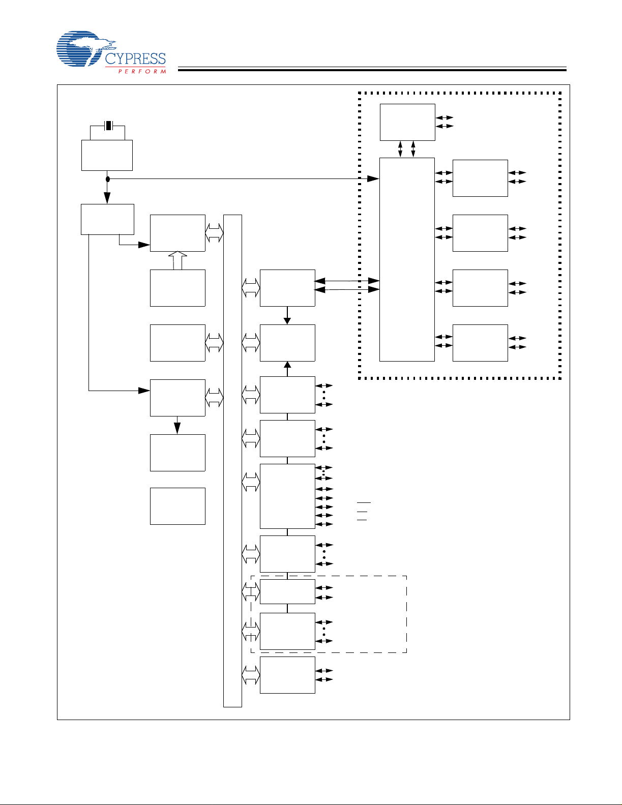
Logic Block Diagram
CY7C66013
CY7C66113
External 6-MHz crystal
PLL
48 MHz
Clock
Divider
6 MHz
12 MHz
12-MHz
8-bit
CPU
PROM
8 KB
RAM
256 byte
12-bit
Timer
8-bit Bus
USB
SIE
Interrupt
Controller
GPIO
PORT 0
P0[0]
P0[7]
USB
Transceiver
Repeater
Power management under firmware
D+[0]
Upstream
USB Port
D–[0]
USB
Transceiver
USB
Transceiver
USB
Transceiver
USB
Transceiver
Downstream USB Ports
control using GPIO pins
D+[1]
D–[1]
D+[2]
D–[2]
D+[3]
D–[3]
D+[4]
D–[4]
Watchdog
Timer
Power-On
Reset
GPIO
PORT 1
GPIO/
HAPI
PORT 2
GPIO
PORT 3
GPIO
PORT 3
DAC
PORT
I2C
Interface
*I2C-compatible interface enabled by firmware through
P2[1:0] or P1[1:0]
P1[0]
P1[7]
P2[0:1,7]
P2[2]; Latch_Empty
P2[3]; Data_Ready
P2[4]; STB
P2[5]; OE
P2[6]; CS
P3[0]
P3[4]
P3[5]
P3[6]
DAC[0]
DAC[7]
CY7C66113C only
SCLK
SDATA
High Current
Outputs
Additional
High Current
Outputs
Document #: 38-08024 Rev. *B Page 9 of 61
C
C
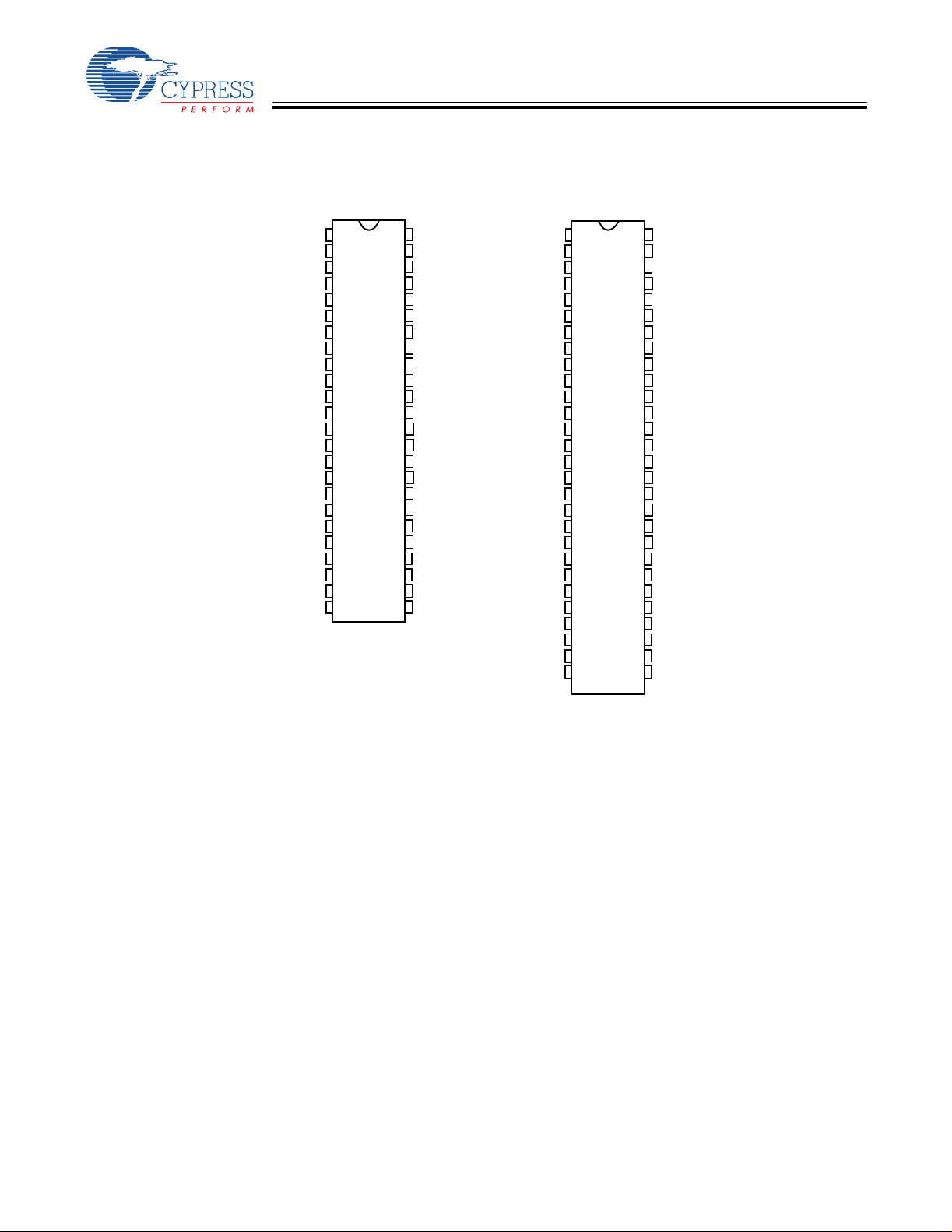
3.0 Pin Configurations
CY7C66013
CY7C66113
XTALOUT
XTALIN
V
REF
P1[3]
P1[5]
P1[7]
P3[1]
D+[0]
D–[0]
P3[3]
GND
D+[1]
D–[1]
P2[1]
D+[2]
D–[2]
P2[3]
P2[5]
P2[7]
GND
P0[7]
P0[5]
P0[3]
P0[1]
CY7C66013C
48-pin SSOP
1
48
2
47
3
46
4
45
5
44
43
6
7
42
8
41
9
40
10
39
11
38
12
37
13
36
14
35
15
34
16
33
17
32
18
31
19
30
29
20
21
28
22
27
23
26
24 25
TOP VIEW
V
CC
P1[1]
P1[0]
P1[2]
P1[4]
P1[6]
P3[0]
D–[3]
D+[3]
P3[2]
GND
P3[4]
D–[4]
D+[4]
P2[0]
P2[2]
GND
P2[4]
P2[6]
V
PP
P0[0]
P0[2]
P0[4]
P0[6]
XTALOUT
XTALIN
V
REF
P1[3]
P1[5]
P1[7]
P3[1]
D+[0]
D–[0]
P3[3]
GND
P3[5]
D+[1]
D–[1]
P2[1]
D+[2]
D–[2]
P2[3]
P2[5]
P2[7]
DAC[7]
P0[7]
P0[5]
P0[3]
P0[1]
DAC[5]
DAC[3]
DAC[1]
CY7C66113C
56-pin SSOP
1
56
2
55
54
3
4
53
5
52
6
51
7
50
8
49
9
48
10
47
11
46
12
45
13
44
43
14
15
42
16
41
17
40
18
39
19
38
20
37
21
36
22
35
23
34
24
33
25
32
26
31
27
30
28
29
V
CC
P1[1]
P1[0]
P1[2]
P1[4]
P1[6]
P3[0]
D–[3]
D+[3]
P3[2]
P3[4]
D–[4]
D+[4]
P3[6]
P2[0]
P2[2]
GND
P2[4]
P2[6]
DAC[0]
V
PP
P0[0]
P0[2]
P0[4]
P0[6]
DAC[2]
DAC[4]
DAC[6]
Document #: 38-08024 Rev. *B Page 10 of 61

C
C
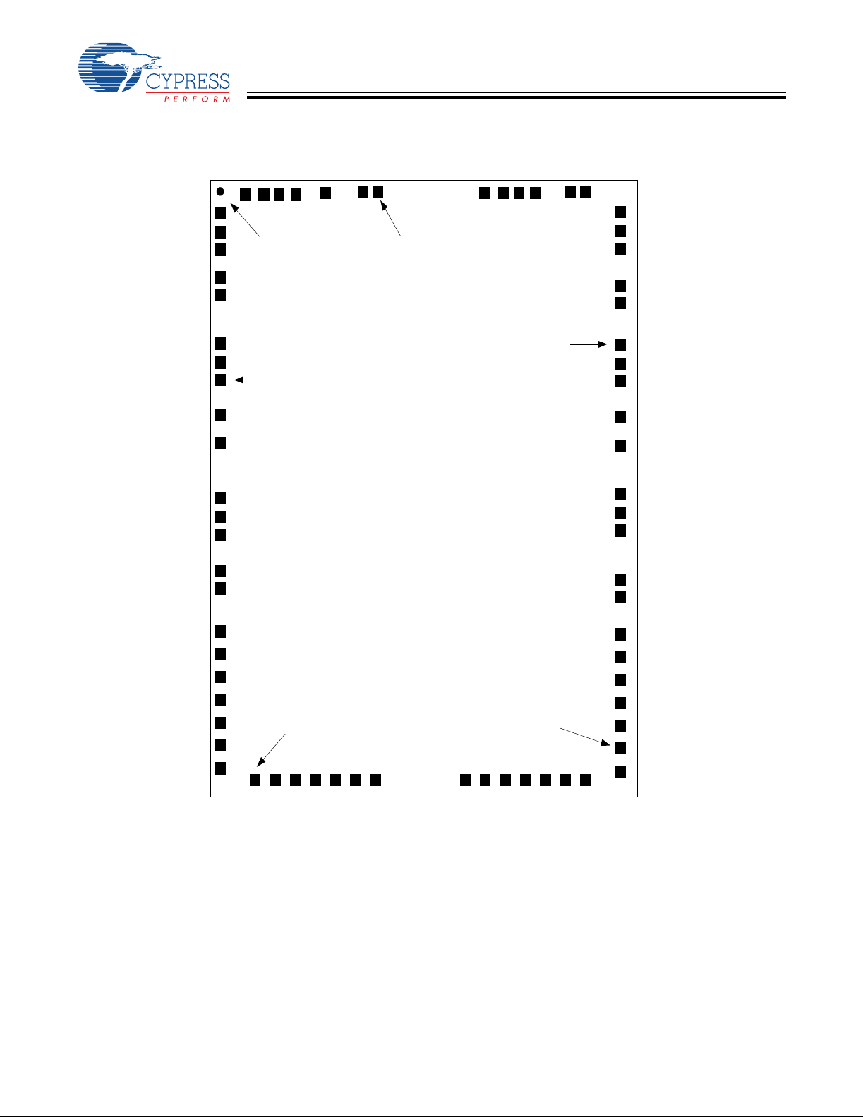
D+[0]
56
P3[1]
55
P1[7]
54
P1[5]
53
P1[3]
52
Vref
51
CY7C66013
CY7C66113
XTALOUT
XTALIN
P1[6]
P1[4]
P1[2]
P1[0]
P1[1]
Vcc
43
44
45
46
47
48
49
50
D-[0]
P3[3]
GND
P3[5]
D+[1]
D–[1]
P2[1]
D+[2]
D–[2]
P2[3]
P2[5]
P2[7]
DAC[7]
P0[7]
10
11
12
13
14
1
2
3
4
5
6
7
8
9
18
17
16
15
DAC[5]
P0[1]
P0[3]
P0[5]
CY7C66113C
56-pin QFN
21
20
19
DAC[6]
DAC[1]
DAC[3]
22
DAC[4]
23
DAC[2]
24
P0[6]
25
P0[4]
26
P0[2]
27
P0[0]
28
Vpp
42
41
40
39
38
37
36
35
34
33
32
31
30
29
P3[0]
D–[3]
D+[3]
P3[2]
P3[4]
D–[4]
D+[4]
P3[6]
P2[0]
P2[2]
GND
P2[4]
P2[6]
DAC[0]
Figure 3-1. CY7C66113C 56-pin QFN Pin Assignment
Document #: 38-08024 Rev. *B Page 1 1 of 61
C
C
(
4)
CY7C66013
CY7C66113
(3398, 419
Cypress Logo
Pin 15
Pin 1
Pin 60
Pin 30 Pin 45
0,0)
Document #: 38-08024 Rev. *B Page 12 of 61
DIE ST EP : 3398 x 4194 m icrons
Die Size: 3322 x 4129 m icrons
Die Thickness: 14 mils = 355.6 microns
Pad Size: 80 x 80 microns
Figure 3-2. CY7C66113C DIE

C
C
CY7C66013
CY7C66113
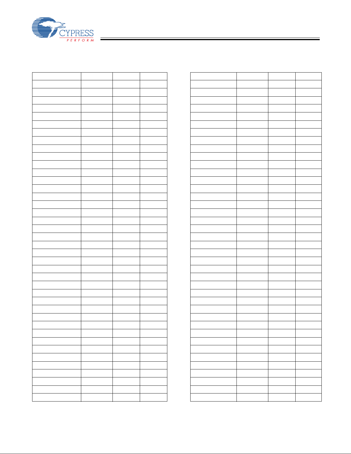
Table 3-1. Pad Coordinates in microns (0,0) to bond pad centers
Pad # Pin Name X Y Pad # Pin Name X Y
1 XtalOut 1274.2 3588.8 37 DAC6 2000.6 210.6
2 XtalIn 1132.8 3588.8 38 DAC4 2103.6 210.6
3 Vref 889.85 3588.8 39 DAC2 2206.6 210.6
4 Port11b 684.65 3588.8 40 Port06 2308.4 210.6
5 Port13 581.65 3588.8 41 Port04 2411.4 210.6
6 Port15 478.65 3588.8 42 Port02 2514.4 210.6
7 Vss 375.65 3588.8 43 Port00 2617.4 210.6
8 Port17 0 3408.35 44 Vpp 2992.4 25.4
9 Port31 0 3162.05 45 DAC0 2992.4 151.75
10 Du+ 0 3060.55 46 Port26 2992.4 306.15
11 Du– 0 2752.4 47 DD+6 2992.4 407.65
12 Port33 0 2650.95 48 DD–6 2992.4 715.75
13 Vss 0 2474.6 49 Port24 2992.4 817.25
14 Port35 0 2368.45 50 Vss 2992.4 923.4
15 DD+1 0 2266.95 51 Port22 2992.4 1086.75
16 DD–1 0 1958.85 52 DD+5 2992.4 1188.25
17 Port37 0 1857.35 53 DD–5 2992.4 1496.35
18 Vref 0 1680.4 54 Port20 2992.4 1597.85
19 Port21 0 1567.4 55 Vref 2992.4 1710.8
20 DD+2 0 1465.95 56 Port36 2992.4 1874.75
21 DD–2 0 1157.85 57 DD+4 2992.4 1976.25
22 Port23 0 1056.35 58 DD–4 2992.4 2284.35
23 Vss 0 880 59 Port34 2992.4 2385.85
24 Port25 0 773.85 60 Vss 2992.4 2492
25 DD+7 0 672.35 61 Port32 2992.4 2655.35
26 DD–7 0 364.25 62 DD+3 2992.4 2756.85
27 Port27 0 262.75 63 DD–3 2992.4 3064.95
28 DAC7 0 100.75 64 Port30 2992.4 3166.45
29 Vss 0 0 65 Port16 2992.4 3412.25
30 Port07 375.2 210.6 66 Port14 2634.2 3588.8
31 Port05 478.2 210.6 67 Port12 2531.2 3588.8
32 Port03 581.2 210.6 68 Port10 2428.2 3588.8
33 Port01 684.2 210.6 69 Port11 2325.2 3588.8
34 DAC5 788.4 210.6 70 VCC 2221.75 3588.8
35 DAC3 891.4 210.6 71 PadOpt 2121.75 3588.8
36 DAC1 994.4 210.6 72
Document #: 38-08024 Rev. *B Page 13 of 61

C
C
CY7C66013
CY7C66113
4.0 Product Summary Tables
4.1 Pin Assignments
Table 4-1. Pin Assignments
Name I/O 48-Pin 56-Pin QFN 5 6-Pi n SSO P Description
D+[0], D–[0] I/O 8, 9 56, 1 8, 9 Upstream port, USB differential data.
D+[1], D–[1] I/O 12, 13 5, 6 13, 14 Downstream port 1, USB differential data.
D+[2], D–[2] I/O 15, 16 8, 9 16, 17 Downstream port 2, USB differential data.
D+[3], D–[3] I/O 40, 41 40, 41 48, 49 Downstream port 3, USB differential data.
D+[4], D–[4] I/O 35, 36 36, 37 44, 45 Downstream port 4, USB differential data.
P0[7:0] I/O 21, 25, 22, 26,
23, 27, 24, 28
P1[7:0] I/O 6, 43, 5, 44, 4,
P2[7:0] I/O 19, 30, 18, 31,
P3[6:0] I/O 37, 10, 39, 7, 4255, 2, 4, 35,
DAC[7:0] I/O n/a 1 3, 18, 19, 20,
XTAL
IN
XTAL
OUT
V
PP
V
CC
GND 1 1, 20, 32, 38 3, 32 11, 40 Ground.
V
REF
45, 47, 46
17, 33, 14, 34
IN 2 50 2 6-MHz crystal or external clock input.
OUT 1 49 1 6-MHz crystal out.
29 28 36 Programming voltage supply, tie to ground during
48 48 56 Voltage supply.
IN 3 51 3 External 3.3V supply voltage for the differential data
14, 15, 16, 17,
24, 25, 26, 27
52, 53, 54, 43,
44, 45, 46, 47
7, 10, 11, 12,
30, 31, 33, 34
38, 39, 42,
21, 22, 23, 29
22, 32, 23, 33,
24, 34, 25, 35
6, 51, 5, 52, 4,
53, 55, 54
20, 38, 19, 39,
18, 41, 15, 42
43, 12, 46, 10,
47, 7, 50
21, 29, 26, 30,
27, 31, 28, 37
GPIO Port 0.
GPIO Port 1.
GPIO Port 2.
GPIO Port 3, capab le of sinking 12 mA (typical).
Digital to Analog Converter (DAC) Port with program-
mable current sink outputs. DAC[1 :0] offer a pro grammable
range of 3.2 to 16 mA typical. DAC[7:2] have a programmable sink current range of 0.2 to 1.0 mA typical.
norma l op e r at io n .
output buffers and the D+ pull-up.
4.2 I/O Register Summary
I/O registers ar e access ed via the I/O Rea d ( IORD) and I/O W rite ( I OWR, IOWX) inst ructi ons. I ORD reads dat a fr om t he sele cted
port into the accumul ator. IOWR performs the reverse; it writes dat a from the accumul ator to the sel ected port . Index ed I/O W rite
(IOWX) adds the contents of X to the address in the instruction to form the port address and writes dat a from the accumula tor to
the specified po rt . Specifying address 0 (e.g., IOWX 0h) means the I/ O regi ster is selected solely by the contents of X.
All undefined registers are reserved. It is important not to write to reserved registers as this may cause an undefined operation
or increased curre nt consumpti on dur in g operat ion. When writing to regi sters with res erved bi ts, the res erved b its must be wr it ten
with ‘0 .’
Table 4-2. I/O Register Summary
Register Name I/O Address Read/Write Function
Port 0 Data 0x00 R/W GPIO Port 0 Data 23 Port 1 Data 0x01 R/W GPIO Port 1 Data 23 Port 2 Data 0x02 R/W GPIO Port 2 Data 23 Port 3 Data 0x03 R/W GPIO Port 3 Data 23 Port 0 Interrupt Enable 0x04 W Interrupt Enable for Pins in Port 0 24 Port 1 Interrupt Enable 0x05 W Interrupt Enable for Pins in Port 1 25 Port 2 Interrupt Enable 0x06 W Interrupt Enable for Pins in Port 2 25 Port 3 Interrupt Enable 0x07 W Interrupt Enable for Pins in Port 3 25
Document #: 38-08024 Rev. *B Page 14 of 61
Page

C
C
CY7C66013
CY7C66113
Table 4-2. I/O Register Summary ( continued)
Register Name I/O Address Read/Write Function
GPIO Configuration 0x08 R/W G PIO Port Configurations 23
2
HAPI and I USB Device Address A 0x10 R/W USB Device Address A 42 EP A0 Counter Register 0x11 R/W USB Address A, Endpoint 0 Counter 44 EP A0 Mode Register 0x12 R/W USB Address A, Endpoint 0 Configuration 43 EP A1 Counter Register 0x13 R/W USB Address A, Endpoint 1 Counter 44 EP A1 Mode Register 0x14 R/W USB Address A, Endpoint 1 Configuration 44 EP A2 Counter Register 0x15 R/W USB Address A, Endpoint 2 Counter 44 EP A2 Mode Register 0x16 R/W USB Address A, Endpoint 2 Configuration 44 USB Status & Control 0x1F R/W USB Upstream Port Traffic Status and Control 41 Global Interrupt Enab le 0x20 R/W Global Interrupt Enab le 32 Endpoint Interru pt Enable 0x21 R/W USB Endpoint Interrupt Enables 32 Interrupt Vector 0x23 R Pending Interrupt Vector Read/Clear 34 Timer (LSB) 0x24 R Lower 8 Bits of Free-running Timer (1 MHz) 27 Timer (MSB) 0x25 R Upper 4 Bits of Free-running T imer 27 WDT Clear 0x26 W Watchdog Timer Clear 21
2
C Control & Status 0x28 R/W I2C Status and Control 28
I
2
C Data 0x29 R/W I2C Data 28
I DAC Data 0x30 R/W DAC Data 26 DAC Interrupt Enable 0x31 W Interrupt Enable for each DAC Pin 26 DAC Int er ru p t P o la rity 0x32 W Interr u pt Po la r ity fo r ea c h DAC P in 26 DAC Isink 0x38-0x3F W Input Sink Current Control for each DAC Pin 26 USB Device Address B 0x40 R/W USB Device Address B (not used in 5-endpoint mode) 42 EP B0 Counter Register 0x41 R/W USB Address B, Endpoint 0 Counter 44 EP B0 Mode Register 0x42 R/W USB Address B, Endpoint 0 Configuration, or
EP B1 Counter Register 0x43 R/W USB Address B, Endpoint 1 Counter 44 EP B1 Mode Register 0x44 R/W USB Address B, Endpoint 1 Configuration, or
Hub Port Connect Status 0x48 R/ W Hub Downstream Port Connect Status 38 Hub Port Enable 0x49 R/W Hub Downstream Ports Enable 38 Hub Port Speed 0x4A R/W Hub Downstream Ports Speed 38 Hub Port Control (Ports [4:1]) 0x4B R/W Hub Downstream Ports Control 39 Hub Port Suspend 0x4D R/W Hub Downstream Port Suspend Control 40 Hub Port Resume Status 0x4E R Hub Downstream Ports Resume Status 40 Hub Ports SE0 Status 0x4F R Hub Downstream Ports SE0 Status 39 Hub Ports Data 0x50 R Hub Downstream Ports Differential data 40 Hub Downstream Force Low 0x51 R/W Hub Downstream Ports Force LOW 39 Processor Status & Control 0xFF R/W Microprocessor Status and Control Register 31
C Configuration 0x09 R/W HAPI Width and I2C Position Configur ati on 27
USB Address A, Endpoint 3 in 5-endpoint mode
USB Address A, Endpoint 4 in 5-endpoint mode
Page
43
44
Document #: 38-08024 Rev. *B Page 15 of 61
C
C
CY7C66013
CY7C66113
4.3 Instruction Set Summary
Refer to the CYASM Assembler User’s Guide for more details.
Table 4-3. Instruction Set Summary
MNEMONIC operand opcode cycles MNEMONIC operand opcode cycles
HALT 00 7 NOP 20 4
ADD A,expr data 01 4 INC A acc 21 4
ADD A,[expr] direct 02 6 INC X x 22 4
ADD A,[X+expr] index 03 7 INC [expr] direct 23 7
ADC A,expr data 04 4 INC [X+expr] index 24 8
ADC A,[expr] direct 05 6 DEC A acc 25 4
ADC A,[X+expr] index 06 7 DEC X x 26 4
SUB A,expr data 07 4 DEC [expr] direct 27 7
SUB A,[expr] direct 08 6 DEC [X+expr] index 28 8
SUB A,[X+expr] index 09 7 IORD expr address 29 5
SBB A,expr data 0A 4 IOWR expr address 2A 5
SBB A,[expr] direct 0B 6 POP A 2B 4
SBB A,[X+expr] index 0C 7 POP X 2C 4
OR A,expr data 0D 4 PUSH A 2D 5
OR A,[expr] direct 0E 6 PUSH X 2E 5
OR A,[X+expr] index 0F 7 SWAP A,X 2F 5
AND A,expr data 10 4 SWAP A,DSP 30 5
AND A,[ex p r] direct 1 1 6 MOV [expr],A direct 31 5
AND A,[X+expr] index 12 7 MOV [X+expr],A index 32 6
XOR A,expr data 13 4 O R [expr],A direct 33 7
XOR A,[expr] direct 14 6 OR [X+expr],A index 34 8
XOR A,[X+expr] index 15 7 AND [expr],A direct 35 7
CMP A,expr data 16 5 AND [X+expr],A i ndex 36 8
CMP A,[expr] direct 17 7 XOR [expr],A direct 37 7
CMP A,[X+expr] index 18 8 XOR [X+expr],A index 38 8
MOV A,expr data 19 4 IOWX [X+expr] index 39 6
MOV A,[expr] direct 1A 5 CPL 3A 4
MOV A,[X+expr] index 1B 6 ASL 3B 4
MOV X,expr data 1C 4 ASR 3C 4
MOV X,[expr] direct 1D 5 RLC 3D 4
reserved 1E RRC 3E 4
XPAGE 1F 4 RET 3F 8
MOV A,X 40 4 DI 70 4
MOV X,A 41 4 EI 72 4
MOV PSP,A 60 4 RETI 73 8
CALL addr 50 - 5F 10 JC addr C0-CF 5
JMP addr 80-8F 5 JNC addr D0-DF 5
CALL addr 90-9F 10 JACC addr E0-EF 7
JZ addr A0-AF 5 INDEX addr F0-FF 14
JNZ addr B0-BF 5
Document #: 38-08024 Rev. *B Page 16 of 61

C
C
CY7C66013
CY7C66113
5.0 Programming Model
5.1 14-bit Program Counter (PC)
The 14-bit Program Counter (PC) allows access to up to 8 KB of PROM available with the CY7C66x13C architecture. The top
32 bytes of the ROM in the 8K part are reserved for testi ng purposes. The program count er is cleared duri ng reset, such that th e
first instr uction executed after a reset is at a ddress 0x0000h. Typically, this is a jump instruction t o a reset handler that initializes
the application (see Section 16.1, Interru pt Vectors, on page 33).
The lower eight bits of the program counter are incremented as instructions are loaded and executed. The upper six bits of the
program counter ar e incr emented by exe cut ing an XPAGE instruction. As a result , the la st inst ruct ion execu ted within a 256- byt e
“page” of sequen tial code should be an XPAGE instructi on. T he assembler direct ive “XPAGEON” causes the assembler to insert
XPAGE instructions automatically. Because instructions can be either one or two bytes long, the assembler may occasionally
need to insert a NOP followed by an XPAGE to execute corr ectly.
The address of the next instr ucti on to be execute d, the carr y flag, and the zer o flag ar e saved as two bytes on the program st ack
during an interrupt acknowledge or a CALL instruction. The program counter, carry flag, and zero flag are restored from the
program stack during a RETI instruction. Onl y the pr ogram counter is restored during a RET instruction.
The program counter cannot be accessed directly by the firmware. The program stack can be ex am ined by reading SRAM from
location 0x00 and up.
Document #: 38-08024 Rev. *B Page 17 of 61

C
C
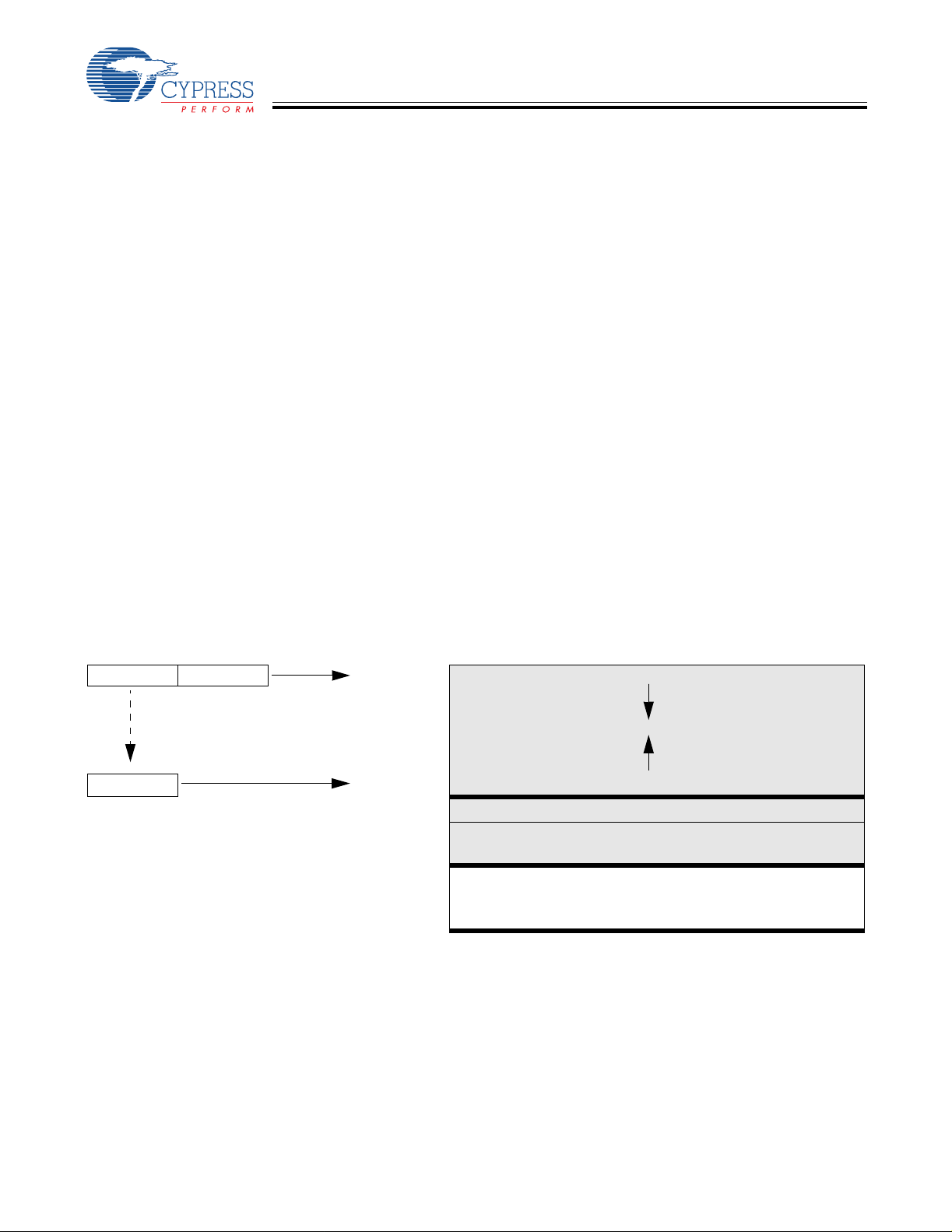
5.1.1 Program Memory Organization
after reset Address 14-bit PC 0x0000
Program execution begins here after a reset
CY7C66013
CY7C66113
0x0002
0x0004
0x0006
0x0008
0x000A
0x000C
0x000E
0x0010
0x0012
0x0014
0x0016
0x0018
USB Bus Reset interrupt vector
128-µs timer interrupt vector
1.024-ms timer i nterrupt vector
USB address A endpoint 0 interrupt vector
USB address A endpoint 1 interrupt vector
USB address A endpoint 2 interrupt vector
USB address B endpoint 0 interrupt vector
USB address B endpoint 1 interrupt vector
Hub interrupt vector
DAC interrupt vector
GPIO/HAPI interrupt vector
I2C interrupt vector
0x001A
0x1FDF
Figure 5-1. Progra m Memory Space with Interr upt Vector Table
Program Memory begins here
8 KB (-32) PROM ends here.
Document #: 38-08024 Rev. *B Page 18 of 61
C
C
CY7C66013
CY7C66113
5.2 8-bit Accumulator (A)
The accumulator is the general-purpose register for the microcontroller.
5.3 8-bit Temporary Register (X)
The “X” regi ster i s avail able to the firmwar e for t emporary storage of int ermediate results. The mi crocontro ller ca n perform indexed
operations based on the value in X. Refer to Section 5.6.3 for addi ti onal information.
5.4 8-bit Progr a m Stack Pointer (PSP)
During a reset, the Program Stack Pointer (PSP) is set to 0x00 and “grows” upward from this address. The PSP may be set by
firmware, using the MOV PSP,A instruction. The PSP supports interrupt service under hardware control and CALL, RET, and
RETI instructions under firmware control. The PSP is not readable by the firmware.
During an interrupt acknowledge, interrupts are disabled and the 14-bit progr am counter, carry flag, and zero flag are written as
two bytes of dat a memory . The f irst byte i s stored in the m emory address ed by the PSP, then the PSP is incre mented. The secon d
byte is stored in memory addressed by the PSP, and the PSP is incremented again. The overall effect is to store the program
counter and flags on the pro gram “stack” and increment th e PSP by two.
The Return From I nterr upt (RETI ) ins truct ion dec remen ts t he PSP, then rest ores t he second b yte from mem ory addr essed by th e
PSP. The PSP is decremente d ag ain and the f irst byte is r estor ed f rom m emory add ressed by t he PSP. After the pro gram count er
and flags hav e be en rest ored f r om sta ck, the i nter rupt s ar e enabl ed. Th e ov erall ef fec t is to r estor e t he prog ram c ounter and flags
from the program stack, decrement the PSP by two, and re-enable interrupts.
The Call Subroutine (CALL) instruction stores the program counter and flags on the program stack and increments the PSP by
two.
The Return From Subroutine (RET) instruction restores the program counter but not the flags from the program stack and
decrements the PSP by two.
5.4.1 Data Memory Organization
The CY7C66x13C microcontrollers provide 256 bytes of data RAM. Normally, the SRAM is partitioned into four areas: program
stack, us er varia bles, data st ack, an d USB endpoi nt FI FOs. The f ol lowing is o ne e xample o f where t he program st ack, dat a st a ck,
and user variable s areas could be located.
After reset Address 8-bit DSP 8-bit PSP 0x00
(Move DSP
8-bit DSP
[1]
)
user selected
0xFF
User variables
USB FIFO sp ace for up to two Addresses and five endpoints
Program Stack Growth
Data Stack Growth
[2]
5.5 8-bit Data Stack Pointer (DSP)
The Data Stack Pointer (DSP) supports PUSH and POP instructions that use the data stack for temporary storage. A PUSH
instruction pre-decrements the DSP, then writes data to the memory location addressed by the DSP. A POP instruction reads
data from the memory lo cation addressed by the DSP, then post-increment s the DSP.
During a reset, the DSP is reset to 0x00. A PUSH instruction when DSP equals 0x00 writes data at the top of the data RAM
(address 0xFF). This writes data to the memory area reserved for USB endpoint FIFOs. Therefore, the DSP should be indexed
at an appropriate memory location that does not compromise the Program Stack, user-defined memory (variables), or the USB
endpoint FIFOs.
Notes:
1. Refer to Section 5.5 for a description of DSP.
2. Endpoint sizes are fixed by the Endpoint Size Bit (I/O register 0x1F, Bit 7), see
Table 19-1.
Document #: 38-08024 Rev. *B Page 19 of 61

C
C
CY7C66013
CY7C66113
For USB applicati ons, t he f irmware should set the DSP to an a ppro priate l ocati on t o avoid a memor y confl ict wit h RAM de dicate d
to USB FIFOs. The memory requirements for the USB endpoints are described in Section 19.2. Example assembly inst ructions
to do this with two device addresses (FIFOs begin at 0xD8) are shown below:
MOV A,20h; Move 20 hex into Accumulator (must be D8h or less)
SWAP A,DSP; swap accumulator value into DSP register.
5.6 Address Mode s
The CY7C66013C and CY7C66113C microcontrollers support three addressing modes for instructions that require data
operands: data, direct, and indexed.
5.6.1 Data (Immediate)
“Data” address mode refers to a data oper and that i s actual ly a const ant encod ed in t he instruct ion. As an example , consid er the
instruction th at loads A with the constant 0xD8:
• MOV A , 0D8h.
This instruction requires two bytes of code where the first byte identifies the “MOV A” instruction with a data operand as the
second byte. The second byte of the instruction is the constant “0xD8”. A constant may be referred to by name if a prior “EQU”
statement assigns the constant value to the name. For example, the following code is equivalent to the example shown above:
• DSPINIT: EQU 0D8h
• MOV A, DSPINIT.
5.6.2 Direct
“Direct” address mode is used when the data operand is a variable stored in SRAM. In that case, the one byte address of the
variable is encoded in the instruction. As an example, consider an instruction that loads A with the contents of memory add ress
loca t ion 0x1 0:
• MOV A, [10h].
Normally , vari able names are assi gned to vari able addresses using “EQU” st atements to improve the reada bility of th e assembler
source code. As an example, the following code is equiva lent to the example shown above:
• buttons: EQU 10h
• MOV A, [buttons].
5.6.3 Indexed
“Indexed” address mode allows the firmware to manipulate arrays of data stored in SRAM. The address of the data operand is
the sum of a const ant encoded i n the ins truct ion and t he con tent s of the “X” regi ster. Normally, the constant is the “base” address
of an array of data and the X regi ster contains an index tha t i ndicates which element of the array is actually addressed:
• array: EQU 10h
•MOV X, 3
• MOV A, [X+array].
This would have the effect of loading A with the fourth element of the SRAM “array” that begins at address 0x10. The fourth
element would be at address 0x13.
6.0 Clocking
XTALOUT
(pin 1)
XTALIN
(pin 2)
30 pF
Figure 6-1. Clock Oscillator On-Chip Circuit
The XTALIN and XTALOUT are the clock pins to the microcontroller. The user can connect an external oscillator or a crystal to
these pins. When using an external crystal, keep PCB traces between the chip leads and crystal as short as possible (less than
To Interna l PLL
30 pF
Document #: 38-08024 Rev. *B Page 20 of 61

C
C
CY7C66013
CY7C66113
2 cm). A 6-MHz fundamental frequ ency parall el resonant cryst al can be connect ed to these pins to provid e a reference frequenc y
for the i nternal PLL. The two internal 30- pF load caps appear in series to the externa l crystal and would be equiva lent to a 15-pF
load. Therefore, the crystal must have a required load capacitance of about 15–18 pF. A ceramic resonator does not allow the
microcontroller to meet the timing specifications of full speed USB and therefore a ceramic resonator is not recommended with
these parts.
An external 6-MHz clock can be applied to the XTALIN pin if the XTALOUT pin is left open. Grounding the XTALOUT pin when
driving XTALIN with an oscillator does not work because the internal clock is effectively shorted to ground.
7.0 Reset
The CY7C66x13C supports t w o resets: POR and a Watchdog Reset (WDR). Each of these resets causes:
• all registe rs to be restored to their defaul t states
• the USB device addresses to be set to 0
• all interr upts to be disabled
• the PSP and DSP to be set to memory address 0x00.
The occurrence of a reset is recorded in the Processor Status and Control Register, as described in Section 15.0. Bits 4 and 6
are used to record the occurrence of POR and WDR, respectively. Firmware can interrogate these bits to determine the cause
of a reset.
Program execution st arts at ROM address 0x0000 after a reset. Although this looks like interrupt vector 0, there is an important
difference. Reset processing does NOT push the program counter, carry flag, and zero flag onto program stack. The firmware
reset handle r shoul d conf ig ure th e hardwar e b efore the “ main” l oop of co de. Att emptin g to e xecut e a RET or RETI in the f irmwar e
reset handler causes unpredictable execution results.
7.1 Power-on Reset
When VCC is first applied to the chip, the POR signal is asserted and the CY7C66x13C enters a “semi-suspend” state. During
the semi-suspend state, which is different from the suspend state defined in the USB specification, the oscillator and all other
blocks of t he part are functi onal, except for t he CPU. This semi-suspend time ensures that both a valid V
that the internal PLL has time to stabilize before full operation begins. When the V
the oscillator is stable, the POR is deasserted and the on-chip timer starts counting. The first 1 ms of suspend time is not
interruptible, and the semi-suspend state continues for an additional 95 ms unless the count is bypassed by a USB Bus Reset
on the upstream port . The 95 ms provides time for V
If a USB Bus Reset occurs on the upstream port during the 95 ms semi-suspend time, the semi-suspend state is aborted and
program execution begins immediately from address 0x0000. In this case, the Bus Reset interrupt is pending but not serviced
until firmware sets the USB Bus Reset Interrupt Enable bit (bit 0 of register 0x20) and enables interrupts with the EI command.
The POR signal is asse rted whenever V
again. Behavior is the same as described above.
drops below appr oximately 2.5V , and remains asser ted until VCC rises above thi s level
CC
to stabilize at a valid operating volt age before the chip executes code.
CC
has risen above approximately 2.5V, and
CC
level is reached and
CC
7.2 Watchdog Reset
The WDR occurs when the internal WDT rolls over. Writing any value to the write-only Watchdog Restart Register at address
0x26 clears the timer. The timer rolls over and WDR occurs if it is not c leared within t
6 of the Processor S tatus and Cont rol Register is set to record t his event (the registe r contents ar e set to 010X0001 by the WDR).
A WDT Reset lasts for 2 ms, after which the microcontroller begins execution at ROM address 0x0000.
t
WATCH
2 ms
(8 ms minimum) of the last clear. Bit
WATCH
Last write to
WDT
Register
Document #: 38-08024 Rev. *B Page 21 of 61
No write to WDT
register, so WDR
goes HIGH
Figure 7-1. Watchdog Reset
Execution begins at
Reset Vector 0x0000

C
C
V
CY7C66013
CY7C66113
The USB transmitter is disabled by a WDR because the USB Device Address Registers are cleared (see Section 19.1).
Otherwise, the USB Control ler would respond to all address 0 transactions.
It is possible for the WDR bit of the Processor Status and Control Register (0xFF) to be set fol lowing a POR event. If a firmware
interrogates the Processor Status and Control Register for a set condition on the WDR bit, the WDR bit should be ignored i f the
POR (bit 3 of register 0xFF) bit is set.
8.0 Suspend Mode
The CY7C66x13C can be placed into a low-power state by setting the Su spend bit of the Processo r Status and Control register.
All logic blocks in the device are turned off except the GPIO interrupt logic and the USB receiver. The clock oscillator and PLL,
as well as the free-running and WDTs, are shut down. Only the occurrence of an enabled G PIO interrupt or non-idle bus activity
at a USB upstream or downst ream port wakes the part from suspend. The Run bit in the Processor Status and Control Register
must be set to resume a part out of suspend.
The clock oscillator restarts immediately after exiting suspend mode. The microcontroller returns to a fully functional state 1 ms
after the oscill ator is stable. The microco ntroller execu tes the instruction fol lowing the I/O write that placed the devic e into suspend
mode before servicing any interrupt requests.
The GPIO interrupt allows the controller to wake- up periodically and poll system component s while maintaini ng a very low average
power consumpti on. To achieve t he lowes t possibl e current duri ng susp end mod e, all I/O sho ul d be hel d a t V
applies to internal port pins that may not be bonded in a par ticular package.
Typical code for entering suspend is shown below:
... ; All GPIO set to low-power state (no floating pins)
... ; Enable GPIO interrupts if desired for wake-up
mov a, 09h ; Set suspend and run bits
iowr FFh ; Write t o Status and Control Regi ster – Enter suspend, wait for USB activity (or GPIO Interrupt)
nop ; This executes before any ISR
... ; Remaining code for exiting suspend routine.
or Gnd. This also
CC
9.0 General-purpose I/O (GPIO) Ports
GPIO
CFG
OE
Internal
Data Bus
Port Write
Port Read
Reg_Bit
STRB
(Latch is Transparent
except in HAPI mode)
Interrupt
Enable
Interrupt
Controller
Data
Out
Latch
Data
In
Latch
Data
Interrupt
Latch
mode
2-bits
Control
Control
Q1
14 kΩ
Q3*
CC
Q2
GPIO
PIN
*Port 0,1,2: Low I
Port 3: High I
sink
sink
Figure 9-1. Block Diagram of a GPIO Pin
Document #: 38-08024 Rev. *B Page 22 of 61

C
C
CY7C66013
CY7C66113
There are up to 31 GPIO pins (P0[7:0], P1[7:0], P2[7:0], and P3[6:0]) for the hardware interface. The number of GPIO pins
changes based on the pa ckag e type of t he chip. Each port c an be conf igur ed as input s wit h inter nal pul l-up s, open dr ain outp uts,
or traditional CMOS outputs. Port 3 offers a higher current drive, with typical current sink capability of 12 mA. The data for each
GPIO port is accessible through the data registers. Port data registers are shown in Figure 9-2 through Figure 9-5, and are set
to 1 on reset.
Port 0 Data ADDRESS 0x00
Bit #76543210 Bit Name P0.7 P0.6 P0.5 P0.4 P0.3 P0.2 P0.1 P0.0 Read/Write R/W R/W R/W R/W R/W R/W R/W R/W Reset11111111
Figure 9-2. Port 0 Data
Port 1 Data ADDRESS 0x01
Bit #76543210 Bit Name P1.7 P1.6 P1.5 P1.4 P1.3 P1.2 P1.1 P1.0 Read/Write R/W R/W R/W R/W R/W R/W R/W R/W Reset11111111
Figure 9-3. Port1 Data
Port 2 Data ADDRESS 0x02
Bit #76543210 Bit Name P2.7 P2.6 P2.5 P2.4 P2.3 P2.2 P2.1 P2.0 Read/Write R/W R/W R/W R/W R/W R/W R/W R/W Reset11111111
Figure 9-4. Port 2 Data
Port 3 Data ADDRESS 0x03
Bit #76 5 43210 Bit Name Reserved P3.6
Read/Write R/W R/W R/W R/W R/W R/W R/W R/W Reset- 1 1 11111
CY7C66113C only
Special care should be taken with any unused GPI O data bits. An unused GPIO data bit, eit her a pin on the chip or a port bit that
is not bonded on a particular package, must not be left floating when the device enters the suspend state. If a GPIO data bit is
left floating, the leakage current caused by the floating bit may violate the suspend current limitation specified by the USB
specifications. If a ‘1’ is written to the unused data bit and the port is configured with open drain outputs, the unused data bit
remains in an indeterminate state. Therefore, if an unused port bit is programmed in open-drain mode, it must be written with a
‘0.’ Notice that the CY7C66013C always requires that P3[7:5] be written with a ‘0.’ When the CY7C66113C is used the P3[7]
should be written with a ‘0.’
In normal non-HAPI mode, reads from a GPIO port always return the present state of the voltage at the pin, independent of the
settings in the Por t Dat a Regist ers. I f HAPI mode is activa ted for a port, reads of that por t return l atched da t a as contr olled by the
HAPI signals (see Section 14.0). During reset, all of the GPIO pins are set to a high impedance input state (‘1’ in open drain
mode). Writi ng a ‘0’ to a GPIO pin drives the pi n LOW . In this st ate, a ‘0’ is always read on t hat GPIO pin unl ess an ext ernal source
overdrives th e int ernal pull-down device.
P3.5
CY7C66113C
only
P3.4 P3.3 P3.2 P3.1 P3.0
Figure 9-5. Port 3 Data
9.1 GPIO Configuration Port
Every GPIO port can be programmed as in puts with internal pull-up s, outputs LOW or HIGH, or Hi-Z (fl oating, the pin i s not driven
internally). In addition, the interrupt polarity for each port can be programmed. The Port Configuration bits (Figure 9-6) and the
Interrupt Enable b it (Figure 9-7 through Figure 9-10) determine the interrupt polarity of the port pins.
GPIO Configuration ADDRESS 0x08
Bit #76543210 Bit Name Port 3
Read/Write R/W R/W R/W R/W R/W R/W R/W R/W Reset00000000
Config Bit 1
Port 3
Config Bit 0
Port 2
Config Bit 1
Port 2
Config Bit 0
Port 1
Config Bit 1
Port 1
Config Bit 0
Port 0
Config Bit 1
Port 0
Config Bit 0
Figure 9-6. GPIO Configuration Register
Document #: 38-08024 Rev. *B Page 23 of 61

C
C
CY7C66013
CY7C66113
As shown in Table 9-1 below, a posi tive po lari ty on an i npu t pin r epresent s a r is ing edge i nter rupt ( LOW to HIGH) , and a n egativ e
polarity on an input pin represents a falling edge interrupt (HIGH to LOW).
The GPIO interrupt is generated when all of the following conditions are met: the Interrupt Enable bit of the associated Port
Interrupt Enable Register is enabled, the GPIO Interrupt Enable bit of the Global Interrupt Enable Register (Figure16-1) is
enabled, th e Interrupt Enabl e Sense (bit 2, Figure 15-1) is set, and the GPIO pin of the port sees an event matchi ng the interr upt
polarity.
The driving state of each GPIO pin is determined by the value written to the pin’s Data Register (Figure 9-2 through Figure 9-5)
and by its associated Port Configuration bits as shown in the GPIO Configuration Register (Figure9-6). These ports are
configured on a per-port basis, so all pins in a given port are configured together. The possible port configurations are detailed
in Table 9-1. As shown in this table below, when a GPIO port is configured with CMOS outputs, interrupts from that port are
disabled.
During reset, all of the bits in the GPIO Configuration Register are written with ‘0’ to select Hi-Z mode for all GPIO ports as the
default configuration.
T able 9-1. GPIO Port Output Control Truth Table and Interrupt Polarity
Port Config Bit 1 Port Con fi g Bit 0 Data Register Output Drive S trength Interrupt Enable Bit Interrupt Polarity
1 1 0 Output LOW 0 Disabled
1 Resistive 1 – (Falling Edge)
1 0 0 Output LOW 0 Disabled
1 Output HIGH 1 Disabled
0 1 0 Output LOW 0 Disabled
1 Hi-Z 1 – (Falling Edge)
0 0 0 Output LOW 0 Disabled
1 Hi-Z 1 + (Rising Edge)
Q1, Q2, and Q3 discussed be low ar e the t ransistors referenced in Figure 9-1. The available GPIO drive strength are:
• Output LOW Mode: The pin’ s Data Register is set to ‘0’
Writing ‘0’ to the pin’s Data Register puts the pin in output LOW mode, regardless of the contents of the Port Configuration
Bits[1:0]. In this mode, Q1 and Q2 are OFF. Q3 is ON. The GPIO pin is driven LOW through Q3.
• Output HIGH Mode: The pin’s Data Register is set to 1 and the Port Conf iguration Bits[1:0] is set to ‘10’
In this mode, Q1 and Q3 are OFF. Q2 is ON. The GPIO is pulled up through Q2. The GPIO pin is capable of sourcing ... of
current.
• Resistive Mode: The pin’s Data Register is set to 1 and the Port Configuration Bits[1:0] is set to ‘11’
Q2 and Q3 are OFF. Q1 is ON. Th e G PIO pin is pulled up wit h an internal 14kΩ resistor. In resi stive mode, the pin may serve
as an input. Reading the pin’s Data Register returns a logic HIGH if the pin is not driven LOW by an external source.
• Hi-Z Mode: The pin’s Data Register is set to1 and Port Configuration Bits[1:0] is set either ‘00’ or ‘01’
Q1, Q2, and Q3 are all OFF. The GPIO pin is not driven internally. In this mode, the pin may serve as an input. Reading the
Port Data Register returns the actual logic value on the port pins.
9.2 GPIO Interru pt Enabl e P orts
Each GPIO pin can be individually enabled or disabled as an interrupt source. The Port 0–3 Interrupt Enable registers provide
this feature with an interrupt enable bit for each GPIO pin. When HAPI mode (Section 14.0) is enabled the GPIO interrupts are
blocked, including ports not used by HAPI, so GPIO pins cannot be used as interrupt sources.
During a reset, GPIO interrupts are disabled by clearing all of the GPIO interrupt enable ports. Writing a ‘1’ to a GPIO Interrupt
Enable bit enables GPIO interrupts from the corresponding input pin. All GPIO pins share a common interrupt, as discussed in
Section 16.8.
Port 0 Interrupt Enable ADDRESS 0x04
Bit #76543210
Bit Name P0.7 Intr
Read/WriteWWWWWWWW
Reset00000000
Enable
P0.6 Intr Enable
P0.5 Intr Enable
P0.4 Intr Enable
P0.3 Intr Enable
Figure 9-7. Port 0 Interrupt Enable
P0.2 Intr Enable
P0.1 Intr Enable
P0.0 Intr Enable
Document #: 38-08024 Rev. *B Page 24 of 61

C
C
CY7C66013
CY7C66113
Port 1 Interrupt Enable ADDRESS 0x05
Bit #76543210
Bit Name P1.7 Intr
Read/WriteWWWWWWWW
Reset00000000
Port 2 Interrupt Enable ADDRESS 0x06
Bit #76543210
Bit Name P2.7 Intr
Read/WriteWWWWWWWW
Reset00000000
Port 3 Interrupt Enable ADDRESS 0x07
Bit #76 5 43210 Bit Name Reserved P3.6 Intr Enable
Read/WriteWW W WWWWW
Reset00 0 00000
Enable
Enable
P1.6 Intr Enable
P2.6 Intr Enable
CY7C66113C
only
P1.5 Intr Enable
P1.4 Intr Enable
P1.3 Intr
Enable
Figure 9-8. Port 1 Interrupt Enable
P2.5 Intr Enable
P2.4 Intr Enable
P2.3 Intr Enable
Figure 9-9. Port 2 Interrupt Enable
P3.5 Intr Enable CY7C66113C only
P3.4 Intr Enable
P3.3 Intr Enable
Figure 9-10. Port 3 Interrupt Enable
P1.2 Intr Enable
P2.2 Intr
Enable
P3.2 Intr Enable
P1.1 Intr Enable
P2.1 Intr Enable
P3.1 Intr Enable
P1.0 Intr Enable
P2.0 Intr Enable
P3.0 Intr Enable
10.0 DAC Port
The CY7C661 13CC fe atures a p rogrammabl e s ink cu rrent 8 bit port which is al so known as DAC por t. Ea ch o f thes e port I/O p ins
have a programmable current sink. Writing a ‘1’ to a DAC I/O pin disables the output current sink (I
pin HIGH through an integrated 14-kΩ resistor. When a ‘0’ is written to a DAC I/O pin, the I
resistor is disabled. This causes the I
DAC port pi n.
Internal
Data Bus
Interrupt
Enable
Interrupt
Polarity
DAC to sink current to drive t he output LOW. Figure 10-1 shows a block diagram of the
sink
V
CC
Q1
14 kΩ
DAC Write
Internal
Buffer
DAC Read
Data
Out
Latch
Suspend
(Bit 3 of Register 0xFF)
Isink
Register
4 bits
Isink
DAC
to Interrupt
Controller
Interrupt Logic
sink
Figure 10-1. Block Diagram of a DAC Pin
DAC) and drives the I/O
sink
DAC is enabled and the pull-up
DAC
I/O Pin
The amount of sink current for the DAC I/O pin is programmabl e over 16 val ues bas ed on the cont ents of the DAC Isink Regist er
(Figure 10-3) for that output pin. DAC[1:0] are high current outputs that are programmable from 3.2 mA to 16 mA (typical).
DAC[7:2] are low current outputs, programmable from 0.2 mA to 1.0 mA (typical).
When the suspend bit in Processor Status and Control Register (Figure 15-1) is set, the Isink DAC block of the DAC circuitry is
disabled. Special care should be taken when the CY7C66113C device is placed in the suspend. The DAC Port Data
Register(Figure 10-2) should normally be loaded with all ‘1’s (Figure 15-1) before setting the suspend bit. If any of the DAC bits
Document #: 38-08024 Rev. *B Page 25 of 61

C
C
CY7C66013
CY7C66113
are set t o ‘0’ when the de vice is suspen ded, that DAC input will float. T he float ing pin could r esult i n excessi ve cur rent co nsumption
by the device, unle ss an external load places the pin in a det erministic state.
DAC Port Data ADDRESS 0x30
Bit #76543210 Bit Name DAC[7] DAC[6] DAC[5] DAC[4] DAC[3] DAC[2] DAC[1] DAC[0] Read/Write R/W R/W R/W R/W R/W R/W R/W R/W Reset11111111
Figure 10-2. DAC Port Data
Bit [1..0]: High Current Outp ut 3.2 mA to 16 mA typical
1= I/O pin is an output pulled HGH through the 14-kΩ resistor. 0 = I/O pin is an input with an internal 14-kΩ pull-up resistor.
Bit [7..2]: Low Current Output 0.2 mA to 1 mA typical
1= I/O pin is an output pulled HGH through the 14-kΩ resistor. 0 = I/O pin is an input with an internal 14-kΩ pull-up resistor.
10.1 DAC Isink Registers
Each DAC I/O pin has an associated DAC Isink register to program the output sink current when the output is driven LOW. The
first Isink register (0x38) co ntrols the current for DAC[0], the secon d (0x39) for DAC[1], and so on until the Is ink register at 0x3F,
controls the curre nt to DAC[7].
DAC Sink Register ADDRESS 0x38 –0x3F
Bit #76543210 Bit Name Reserved Reserved Reserved Reserved Isink[3] Isink[2] Isink[1] Isink[0] Read/Write WWWW Reset - - - - 0 0 0 0
Figure 10-3. DAC Sink Register
Bit [3.. 0] : Is in k [x ] (x = 0..3)
Writing all ‘0’s to the Isink register causes 1/5 of the max current to flow through the DAC I/O pin. Writing all ‘1’s to the Isink
register provides the maximum current flow through the pin. The other 14 states of the DAC sink current are evenly spaced
between these two valu es.
Bit [7..4]: Reserved
10.2 DAC Port Interrupts
A DAC port interrupt can be enabled/disabled for each pin individually. The DAC Port Interrupt Enable register provides this
feature with an in terrupt enable b it f or each DAC I/ O pin. All o f the DAC Port I nterrupt Enab le reg ister bi t s are clear ed to ‘ 0’ dur in g
a reset. All DAC pins share a common in terrupt, as explained in Section 16.7.
DAC Port Interrupt ADDRESS 0x31
Bit #76543210 Bit Name Enable Bit 7 Enable Bit 6 Enable Bit 5 Enable Bit 4 Enable Bit 3 Enable Bit 2 Enable Bit 1 Enable Bit 0 Read/WriteWWWWWWWW Reset00000000
Figure 10-4. DAC Port Interrupt Enable
Bit [7..0]: Enable bit x (x= 0..7)
1 = Enables interrupts from the corresponding bit position; 0= Disables interrupts from the corresponding bit position
As an additional benefit, the interrupt polarity for each DAC pin is programmable with the DAC Port Interrupt Polarity register.
Writing a ‘0’ to a bit selects negative polar it y (falling edge) that causes an interrupt (if enabled) if a fall ing edge transition occurs
on the corresponding input pin. Writing a ‘1’ to a bit in this register selects positive polarity (rising edge) that causes an interrupt
(if enabled) if a rising edge transi tion occurs on t he cor respondi ng input pin. All of the DAC Port Interrup t Polar ity re giste r bit s are
cleared during a reset.
DAC IO Interrupt Polarity ADDRESS 0x32
Bit #76543210 Bit Name Polarity Bit 7 Polarity Bit 6 Polarity Bit 5 Polarity Bit 4 Polarity Bit 3 Polarity Bit 2 Polarity Bit 1 Polarity Bit 0 Read/WriteWWWWWWWW Reset00000000
Figure 10-5. DAC Port Interrupt Polarity
Document #: 38-08024 Rev. *B Page 26 of 61

C
C
1.024-ms interrupt
N
CY7C66013
CY7C66113
Bit [7.. 0] : P o la rity bit x (x= 0. .7 )
1= Selects positive polarity (rising edge) that causes an interrupt (if enabled);
0 = Selects negative polarity (falling edge ) tha t causes an interrupt (if enabled).
11.0 12-bit Free-running Timer
The 12-bit timer operates with a 1-µs tick, provid es two interrupts (128 µs and 1.024 m s) and allows the firmware to directl y time
events that are up to 4 ms in duration. The lower eight bits of the timer can be read directly by the firmware. Reading the lower
8 bits latches the upper four bits into a temporary register. When the firmware reads the upper four bits of the timer, it is actually
reading the count stored in the temporary register. The effect of this is to ensure a stable 12-bit timer value can be read, even
when the two reads are separated in time.
Timer LSB ADDRESS 0x24
Bit #7654 321 0 Bit Name Timer Bit 7 Timer Bit 6 Timer Bit 5 Timer Bit 4 Timer Bit 3 Timer Bit 2 Timer Bit 1 Timer Bit 0 Read/WriteRRRRRRRR Reset 0 0 0 0 0 0 0 0
Figure 11- 1. Timer LSB Register
Bit [7:0]: Timer lo wer eight bits
Timer MSB ADDRESS 0x25
Bit #7654 321 0 Bit Name Reserved Reserved Reserved Reserved Timer Bit 11 Timer Bit 10 Timer Bit 9 Timer Bit 8 Read/Write - - - - R R R R Reset 0 0 0 0 0 0 0 0
Figure 11-2. Timer MSB Register
Bit [3:0]: Timer higher ni bble
Bit [7:4]: Reserved
128-µs interrupt
10 9 7856432
1 011
1-M H z cl ock
L1 L0L2L
D3 D2 D1 D0 D7 D6 D5 D4 D3 D2 D1 D0
Figure 11- 3. Timer Block Diagram
8
12.0 I2C and HAPI Configuration Register
Internal hardware supports communication with external devices through two interfaces: a two-wire I2C-compatible, and a HAPI
for 1, 2, or 3 byte transfers. The I
common configuration register (see Figure 12-1)
2
C Configuration ADDRESS 0x09
I
Bit #7654 321 0
2
Bit Name I
Read/Write R/W - R/W R/W R R R/W R/W Reset 0 0 0 0 0 0 0 0
ote:
3. I2C-compatible function must be separately enabled, as described in Section 13.0.
C Position Reserved LEMPTY
2
C-compatible and HAPI functions, discussed in detail in Sections 13.0 and 14.0, share a
[3]
. All bits of this register are cleared on reset.
Polarity
DRDY
Polarity
Latch
Empty
Figure 12-1. HAPI/I2C Configuration Register
To Timer Registers
Data
Ready
HAPI Port Width Bit 1
HAPI Port Width Bit 0
Document #: 38-08024 Rev. *B Page 27 of 61

C
C
CY7C66013
CY7C66113
2
Bits [7, 1:0 ] of t he HAP I/I
Bits [5:2] are used in HAPI mode only, and are described in Section 14.0. Table 12-1 shows the HAPI port configurations, and
Table 12-2 shows I
packages, and to al low si m ultaneous HAPI and I
HAPI operation is enab led whene ver ei ther HAPI Port Wid th Bit ( Bit 1 o r 0) i s n on-zero . This aff ects GPIO o perati on as des cr ibed
in Section 14.0. The I
Table 12-1. HAPI P or t Co n fi g ur a ti o n
Port Width (Bi t 0 and 1, Figure 12-1) HAPI Port Width
2
Ta ble 1 2-2. I
2
I
C Port Configuration
C Position (Bit 7, Figure 12-1)I
Don’t Care 1 I
13.0 I2C-compatible Controlle r
The I2C-compatible block provides a versatile two-wire communication with external devices, supporting master, slave, and
multi-master modes of operat ion. Th e I
interrupts as needed to allow firmware to take appropriate action during transactions. While waiting for firmware response, the
hardware keeps the I
2
C-compatibl e interface generate s an interrupt to the microcontroller at the end of each received or transmitted byte, when
The I
a stop bit is detected by th e slave when in receive mode, or when arbitration is lost. Details of the in ter rupt responses are given
in Section 16.9.
2
The I
C-compatibl e int erfac e consi sts of two reg isters, a n I2C Data Register (Figure 13-1) and an I2C Sta tus and Con tr ol Reg ister
(Figure 13-2). The Data Register is implemented as separate read and write registers. Generally, the I
Register shoul d only be moni tored af ter t he I
read misleading bit status if a transaction is underway.
2
The I
C SCL clock is connected to bit 0 of GPIO port 1 or GPIO port 2, and the I2C SDA data is connected to bit 1 of GPIO port
1 or GPIO port 2. Refer to Section 12.0 for the bit definitions and functionality of the HAPI/I
used to set the l ocations of the configurable I
Status & Control Register, the two LSB ([1:0]) of the corresponding GPIO port is placed in Open Drain mode, regardless of the
settings of the GPIO Configuration Register. The electrical characteristics of the I
GPIO ports 1 and 2. Note that the I
All control of the I
2
I
C Data ADDRESS 0x29
Bit #7654 321 0
Bit Name I
Read/Write R/W R/W R/W R/W R/W R/W R/W R/W
Reset X X X X X X X X
2
2
C Data 7 I2C Data 6 I2C Data 5 I2C Data 4 I2C Data 3 I2C Data 2 I2C Data 1 I2C Data 0
C Configuration Register control the pin out configuration of the HAPI and I2C-compatible interfaces.
2
C pin location configuration options. These I2C-compatible options exist due to pin limitations in certain
2
C-compatibl e interface must be separat ely enabled as described in Section13.0.
2
C-compatible operation.
11 24 Bits: P3[7:0], P1[7:0], P0[7:0]
10 16 Bit s: P1[7:0], P0[7:0]
01 8 Bits : P0 [ 7: 0 ]
00 No HAPI Interface
2
C Port Width (Bit 1, Figure 12-1)I
2
C on P2[1:0], 0:SCL, 1:SDA
2
00I
10I
2
C-compatibl e block functi ons by handling t he low-level si gnaling in har dware, and issuin g
2
C-compatibl e bus idle if necessary.
2
C interrupt, as all bi ts ar e valid at tha t time. Polling th is regi ster at other t imes coul d
2
C pins. Once the I2C-compatibl e functionality is enabl ed by setting bit 0 of the I2C
2
(max) is 2 mA @ V
OL
= 2.0V for ports 1 and 2.
OL
C on P1[1:0], 0:SCL, 1:SDA
2
C on P2[1:0], 0:SCL, 1:SDA
2
C Configuration Register, which is
C-compatible interface is the same as that of
2
C Position
2
C Status and Control
C clock and data lines is performed by the I2C-compatible block.
Figure 13-1. I2C Data Register
Bits [7..0]: I2C Data
2
Contains 8-bit data on the I
2
I
C Status and Control ADDRESS 0x28
Bit #7654 321 0 Bit Name MSTR Mode Continue/Busy Xmit Mode ACK Addr ARB
Read/Write R/W R/W R/W R/W R/W R/W R/W R/W Reset 0 0 0 0 0 0 0 0
C Bus.
Lost/Restart
Received Stop I
2
C Enable
Figure 13-2. I2C Status and Control Register
Document #: 38-08024 Rev. *B Page 28 of 61

C
C
CY7C66013
CY7C66113
2
C Status and Control register bits are defined in Table 13-1, with a more detailed description fol lowing.
The I
Ta ble 1 3-1. I
Bit Name Description
0I
1 Received Stop Reads 1 only in slave receive mode, when I
2 ARB Lost/Restart Reads 1 to indicate master has lost arbitration. Reads 0 otherwise.
3 Addr Reads 1 during first byte after start/restart in slave mode, or if master loses arbitration.
4 ACK In receive mode, write 1 to gener ate ACK, 0 for no ACK.
5 Xmit Mode Writ e to 1 for transmit mode, 0 for receive mode .
6 Continue/Busy Write 1 to indicate ready for next transaction.
7 MSTR Mode Write to 1 for master mode, 0 for slave mode. This bit is cleared if master loses arbi tr ation.
Bit 7: MSTR Mode
Bit 6: Continue/Busy
Bit 5: Xm it Mode
Bit 4: ACK
Bit 3: Addr
Bit 2: ARB Lost/Restart
2
C Status and Contr ol Regi ster Bit Definitions
2
C Enable When set to ‘1’, the I2C-compatible function is enabled. When cleared, I2C GPIO pins operate
normally.
2
C Stop bi t det ect ed (u nless firmwar e d id not ACK the
last transaction).
Write to 1 in master mode to perform a restart sequence (also set Continue bit).
Reads 0 otherwise. This bit should always be written as 0.
In transmit mode, reads 1 i f ACK was received, 0 if no ACK received.
Reads 1 when I
2
C-compatibl e block is busy with a transaction, 0 when transaction is complete.
Clearing from 1 to 0 generat es Stop bit.
2
Setting this bit to 1 causes the I
C-compatible block to initiate a master mode transaction by sending a start bit and
transmitting the first data byte from the data reg ister (this typic ally holds the targ et address and R/W bit). Subsequent byte s
are initiated by setting the Continue bit, as described below.
Clearing this bit (set to 0) causes the GPIO pins to operate normally
In master mode, the I
transmit or receive state. The I
2
C-compatible block generates the clock (SCK), and drives the data line as required depending on
2
C-compatible block performs any required arbitration and clock synchronization. IN the
event of a loss of arbitration, this MSTR bit is cleared, the ARB Lost bit is set, and an interrupt is generated by the
microcontroller. If the chip is the target of an external master that wins arbitration, then the interrupt is held off until the
transactio n from the external master is completed.
When MSTR Mode is cleared from 1 to 0 by a firmware write, an I
2
C Stop bit is generated.
This bit is writ ten by the fir mware t o indi cate t hat the fir mware is ready for the next b yte tran sacti on to b egi n. In other words,
the bit has r esponded to an interrupt request and has completed the require d update or read of the data register. During a
read this bit ind icate s if the hardware i s busy and i s locki ng out addi tio nal wri tes to t he I
locking allows the hardware to complete certain operations that may re quire an extended period of time. Following an I
interrupt, the I
2
C-compatible block does not return to the Busy state until firmware sets the Continue bit. This allows the
2
C Status and Control regis ter . This
firmware to make one control register write without the need to che ck the Busy bit.
This bit is set by firmware to enter transmit mode and perform a data transmit in master or slave mode. Clearing this bit
sets the part in receive mod e. Firmware generally determines the value of this bit from t he R/W bit associated wi th the I
address packet. The Xmit Mode bit state is ignored when init ially writing t he MSTR Mode or the Restart bits, as these case s
always cause transmi t mode for the first byte.
This bit is set or cleared by firmware during receive operation to indicate if the hardware should generate an ACK signal
2
on the I
C-compatibl e bus. Writing a 1 to this bit generat es an ACK (SDA LOW) on the I2C-compatible bus at the ACK bit
time. During transmits (Xmit Mode = 1), this bit should be cleared.
2
This bi t is set by th e I
C-compatible block during the first byte of a slave receive transaction, after an I2C start or restart.
The Addr bit is cleared when the firmware sets the Continue bi t. This bit allows the firmware to r ecognize when the mast er
has lost arbitrat ion, and in slave mode it allows the firmware to recognize that a start or restart has occurred.
This bit is valid as a status bit (ARB Lost) after master mode transactions. In master mode, set this bit (along with the
Continue and MSTR Mode b it s) to perform an I
2
C restart sequence. The I2C target add ress for the restart must be written
to the data regist er before setti ng the Continue bit. T o pre vent false ARB Lost si gnals, the Resta rt bit is clear ed by hardware
during the restart sequence.
2
C
2
C
Document #: 38-08024 Rev. *B Page 29 of 61

C
C
CY7C66013
CY7C66113
Bit 1: Receive Stop
This bit is set when the slave is in receive mode and detects a stop bit on the bus. The Receive Stop bit is not set if the
firmware terminates the I
e.g. in receive mode if firmware sets the Continue bit and clears the ACK bit.
2
Bit 0: I
C Enable
Set this bit to overri de GPIO defini tion with I
these pins are free to function as GPIOs. In I
of the GPIO configura ti on setting.
14.0 Hardware A ssisted Pa r al le l Interface (HA PI)
The CY7C66x13C proc essor provides a hardware assisted paral lel interface for bus widths of 8, 16, or 24 bits, to acc om mo date
data transfer with an external microcontroller or similar device. Control bits for selecting the byte width are in the HAPI/I
Configuration Regi ster (Figure 12-1), bits 1 and 0.
Signals are provided on Port 2 to control the HAPI interface. Table 14-1 describes these signals and the HAPI control bits in the
2
HAPI/I
overridden. The Port 2 output pins are in CMOS output mode and Port 2 input pins are in input mode (open drain mode with Q3
OFF in Figure 9-1).
T able 14-1. Port 2 Pin and HAPI Configuration Bit Definitions
C Configuration Regi ster. Enabling HAPI causes the GPIO setting in th e GPIO Confi guration Register (Figure 9-6) to be
Pin Name Direction Description (Port 2 Pin)
P2[2] LatEmptyPin Out Ready for more input data from external interface.
P2[3] DReadyPin Out Output data ready for external interface.
P2[4] STB In Strobe signal for latching incoming dat a.
P2[5] OE In Output Enable, causes chip to output dat a.
P2[6] CS In Chip Select (Gates STB
Bit Name R/W Description (HAPI/I
2 Data Ready R Asserted after firmware writes data to Port 0, until OE
3 Latch Empty R Asserted after firmware reads data from Port 0, until STB
4 DRDY Polarity R/W Determines polarity of Data Ready bit and DReadyPin:
5 LEMPTY Polarity R/W Determines polarity of Latch Empty bit and LatEmptyPin:
2
C transaction by not acknowledging the previous byte transmitted on the I2C-compatible bus,
2
C-compatible fun ction on t he two I2C-compatib le pins. When thi s bit is cleared,
2
C-compatible mode, the two pins operate in open drain mode, independent
and OE).
2
C Configuration Registe r)
driven LOW .
driven LOW.
If 0, Data Ready is active LO W, DReadyPin is active HIGH.
If 1, Data Re a dy is ac tiv e HI GH , D R e ady P in is a ct iv e LOW.
If 0, Latch Empty is active LOW, LatEmptyPin is active HIGH.
If 1, Latch Empty is active HIGH, LatEmptyPin is active LOW.
2
C
HAPI Read by External Device from CY7C66x13C:
In this case (see Figure 25-3), firmware wri tes data to the GPIO port s. I f 16-bit or 24-bit tran sfers are being made, Port 0 sh ould
be written last, since writes to Port 0 asserts the Data Ready bit and the DReadyPin to signal the external device that data is
available.
The external device then drives the OE
When OE
for the next output, again writing Port 0 last.
The Data Ready bit reads the opposite state from the external DReadyPin on pin P2[3]. If the DRDY Polarity bit is 0, DReadyPin
is active HIGH, and the Data Ready bit is active LOW.
HAPI Write by External Device to CY7C66x13C:
In this case (see Figure 25-4), the external device drives the STB
port pins. When this happens, the internal latches become full, which causes the Latch Empty bit to be deasserted. When STB
is returned HIGH (inactive), the HAPI/GPIO interrupt is generated. Firmware then reads the parallel ports to empty the HAPI
latches. If 16- bit or 24-bi t tran sfers a re be ing made, Port 0 sho uld be read l ast becau se re ads fro m Port 0 assert the Lat ch Empty
bit and the LatEmptyPin to signal the external device for more data.
The Latch Empty bit reads the opposite state from the external LatEmptyPin on pin P2[2]. If the LEMPTY Polarity bit is 0,
LatEmptyPin is activ e HIGH , and the Latch Empty bit is active LOW.
Document #: 38-08024 Rev. *B Page 30 of 61
is returned HIGH (inactive) , the HAPI/GPIO interr upt is generated. At that point, fir mware can reload the HAPI latches
and CS pins active (LOW), which causes the HAPI data to be output on the port pins.
and CS pins active (LOW) when it drives new data onto the

C
C
CY7C66013
CY7C66113
15.0 Processor Status and Control Register
Processor Status and Control ADDRESS 0xFF
Bit #76543210
Bit Name IRQ
Read/Write R R/W R/W R/W R/W R R/W R/W Reset 0 0 0 1 0 0 0 1
Pending
Bit 0: Run
This bit is manipulated by the HALT instruction. When Halt is executed, all the bits of the Processor Status and Control
Register are clear ed to 0. Since the run bit is cl eared, the processor st ops at the end of the current instructio n. The processor
remains halted until an appropriate reset occurs (power-on or Watchdog). This bit should normally be written as a ‘1 .’
Bit 1: Reserved
Bit 1 is reserved and must be written as a zero.
Bit 2: In te rrupt Enab le Sense
This bit indicates whether interrupts are enabled or disabled. Firmware has no direct control over this bit as writing a zero
or one to this bit position has no effect on interrupts. A ‘0’ indicates that interrupts are masked off and a ‘1’ indicates that
the interrupt s are ena bled. This b it i s fur the r gate d with the bi t set ting s of t he Global Inter rupt Enable Reg is ter ( Figure 16-1)
and USB End Point Interrupt Enable Regi ster (Figure 16-2). Instructions DI, EI, and RETI manipulate the state of this bit.
Bit 3: Suspend
Writing a ‘1’ to the Suspend bit halts the processor and cause the microcontroller to enter the suspend mode that significantly reduces power consumption. A pending, enabled interrupt or USB bus activity causes the device to come out of
suspend. Afte r coming out of suspen d, the devi ce resume s firmware exec ut ion at t he instruct i on followi ng the IOW R which
put the part into suspend. An IOWR attempting to put the part into suspend is ignored if USB bus activity is present. See
Section 8.0 for more details on suspend mode operation.
Bit 4: Power-on Reset
The Power-on Reset is set to ‘1’ during a power-on reset. The firmware can check bits 4 and 6 in the reset handler to
determine whethe r a reset was caused by a power-on condition or a Watchdog timeout. A POR eve nt may be followed by
a WDR before firmware begins executing, as explained below.
Bit 5: USB Bus Reset Interrupt
The USB Bus Reset Interrupt bit is set when the USB Bus Reset is detected on receiving a USB Bus Reset signal on the
upstream port. The USB Bus Reset signal is a single-ended zero (SE0) that lasts from 12 to 16 µs. An SE0 is defined as
the condition in which both the D+ line and the D– line are LOW at the same time.
Bit 6: WDR
The WDR is set during a reset initiated by the WDT. This indicates the WDT went for more than t
between Watchdog clears. This can occur with a POR event, as note d below.
Bit 7: IRQ Pending
The IRQ pending, when set, indicate s that one or more of the interrupts has been recognized as act ive. An interrupt remains
pending until its interrupt enable bit is set (Figure 16-1, Figure 16-2) and interrupts are globally enabled. At that point, the
internal interrupt handling sequence clears this bit until another interrupt is detected as pending.
During power-up, the Processor Status and Control Register is set to 00010001, which indi cates a POR (bit 4 set) has occurred
and no interrupts are pending (bit 7 clear). During the 96 ms suspend at start-up (explained in Section 7.1), a WDR also occurs
unless this suspend i s aborted by an up stream SE0 befor e 8 ms. If a WDR occurs during t he power-up suspe nd interval , firmware
reads 01010001 from the St atus and Control Regist er after power-up. Normally, the POR bit should be cleared so a subsequent
WDR can be clear ly i denti fied. I f an upst ream bus res et is recei ved before fir mware exam ines t his r egist er, the Bus Reset bit may
also be set.
During a WDR, the Processor Status and Control Register is set to 01XX0001, which indicates a WDR (bit 6 set) has occurred
and no interrupts are pending (bit 7 clear). The WDR does not effect the state of the POR and the Bus Reset In terrupt bits.
Watchdog
Reset
USB Bus Reset Interrupt
Power-On Reset
Suspend Interrupt
Figure 15-1. Processor Status and Control Register
Enable Sense
Reserved Run
(8 ms minimum)
WATCH
16.0 Interrupts
Interrupts are generated by the GPIO/DAC pins, the in ter nal timers, I2C-compatible or HAPI operation, the internal USB hub, or
on various USB traffic conditions. All interrupts are maskable by the Global Interrupt Enable Register and the USB End Point
Interrupt Enable Regi ster. Wr it ing a ‘1’ to a bit position enables the interrupt associated with that bit position.
Document #: 38-08024 Rev. *B Page 31 of 61

C
C
CY7C66013
CY7C66113
Global Inter rupt Enable Register ADDRESS 0X20
Bit #76543210 Bit Name Reserved I
Read/Write - R/W R/W R/W R/W R/W R/W R/W Reset - 0000000
Bit 0: USB Bus RST Interrupt Enable
1 = Enable Interrupt on a USB Bus Reset; 0 = Disable int errupt on a USB Bus Reset (refer to section 16.3).
Bit 1: 128-µs Interru pt En a b le
1 = Enable Timer in terrupt every 128 µs; 0 = Disable Timer Interrupt for every 128 µs.
Bit 2: 1.024-ms Interrupt Enable
1= Enable Timer interrupt every 1.024 ms; 0 = Disable Timer Interrupt every 1.024 ms.
Bit 3: USB Hub Interrupt Enable
1 = Enable Interrupt on a Hub status change; 0 = Disable interrupt due to hub status change. (Refer to section 16.6.)
Bit 4: DAC Interrupt Enable
1 = Enable DAC Interrupt; 0 = Disable DAC interrupt.
Bit 5: GPIO Interrupt Enable
1 = Enable Interrupt on falling/rising edge on any GPIO; 0 = Disable Interr upt on falling/ri sing edge on any GPIO. (Refer to
sections 16.8, 9.1, and 9.2.)
2
Bit 6: I
C Inter rup t Enable
1 = Enable Interrupt on I2C related activity; 0 = Disable I2C related activity interrupt. (Refer to section 16.9.)
Bit 7: Reserved.
USB Endpoi nt Int errupt E nabl e ADDRESS 0X21
Bit #76543210 Bit Name Reserved Reserved Reserved EPB1 Interrupt
Read/Write---R/WR/WR/WR/WR/W
Reset ---00000
2
C Interrupt
Enable
GPIO Interrupt Enable
DAC Interrupt Enable
USB Hub Interrupt Enable
Figure 16-1. Global Interrupt Enable Register
Enable
EPB0 Interrupt Enable
Figure 16-2. USB Endpoint Interrupt Enable Register
1.024-ms Interrupt Enable
EPA2 Interrupt Enable
128-µs
Interrupt
Enable
EPA1 Interrupt Enable
USB Bus RST Interrupt Enable
EPA0 Interrupt Enable
Bit 0: EPA0 Interrupt Enable
1 = Enable Interrupt on dat a activity through endpoint A0; 0 = Disable Interrupt on data act ivity through endpoint A0.
Bit 1: EPA1 Interrup t Ena b le
1 = Enable Interrupt on dat a activity through endpoint A1; 0 = Disable Interrupt on data act ivity through endpoint A1.
Bit 2: EPA2 Interrup t Ena b le
1 = Enable Interrupt on dat a activity through endpoint A2; 0 = Disable Interrupt on data act ivity through endpoint A2.
Bit 3: EPB0 Interrupt Enable
1 = Enable Interrupt on dat a activity through endpoint B0; 0 = Disable Interrupt on data act ivity through endpoint B0.
Bit 4: EPB1 Interrupt Enable
1 = Enable Interrupt on dat a activity through endpoint B1; 0 = Disable Interrupt on data act ivity through endpoint B1.
Bit [7..5]: Reserved
During a reset, the contents the Global Interrupt Enable Register and USB End Point Interrupt Enable Register are cleared,
effecti vely, disabling all interrupt s.
The interrupt con tr oller con t ains a sep arat e fli p-fl op for e ach int errupt . See Figure 16-3 for the logic bl oc k diagr am of the i nterr upt
controller. When an interrupt is gener ated, it i s fi rst re gistered as a pendi ng int errup t. It stay s pending unti l it i s servi ced or a reset
occurs. A pending interrupt only generates an interrupt request if it is enabled by the corresponding bit in the interrupt enable
registers. The highest priority interrupt request is serviced following the completion of the currently executing instruction.
Document #: 38-08024 Rev. *B Page 32 of 61

C
C
e
CY7C66013
CY7C66113
When servicing an interrupt, the hardware does the following:
1. Disables all interrupts by cl earing the Global Interrupt Enable bit in the CPU (the state of this bit can be read at Bi t 2 of t he
Processor Status and Control Register, Figure15-1).
2. Clears the flip-flop of the current int errupt.
3. Generates an automatic CALL instruction to the ROM address associated with the interrupt being serviced (i.e., the Interrupt
Vect or, see Section 16.1).
The instruct ion in the interrupt t able is typically a JMP instruction to the address of the Interrupt Service Routine (ISR) . The user
can re-enable interrupts in the interrupt service routine by execut ing an EI instruction. Interrupts can be nested to a leve l limited
only by the availa ble stack space.
The Program Counter value as well as the Carry and Zero flags (CF, ZF) are stored onto the Program Stack by the automatic
CALL instruction generated as part of the interrupt acknowledge process. The user f ir m ware is responsible fo r ensuring that the
processor state is preserved and restored during an interrupt. The PUSH A instruction should typically be used as the first
command in the ISR to save the accumul ator value and the POP A instruction should be used to rest ore the accumulator value
just before the RETI instruction. The program counter CF and ZF are restored and interrupts are enabled when the RETI
instruction is executed.
The DI and EI instructions can be used to disable and enable interrupts, respectively. These instructions affect only the Global
Interrupt Enable bit of the CPU. If desired, EI can be used to re-enable interrupts while inside an ISR, instead of waiting for the
RETI that exists the ISR. While the global interrupt enable bit is cleared, the presence of a pending interrupt can be detected by
examining the IRQ Sense bi t (Bi t 7 in the Processor St atus and Control Register).
16.1 Interr upt Vectors
The Interrupt Vectors supported by the USB Controller are listed in Table 16-1. The lowest-numbe red i nterrupt (USB Bus Reset
interrupt) has the highest priority, and the highest-numbered interrupt (I
USB Reset Clear
1
USB Reset Int
1
AddrA ENP2 Int
I2C Int
CLR
D
Q
Enable [0]
CLK
CLR
D
CLK
CLR
1
D
CLK
(Reg 0x 20 )
Q
Enable [2]
(Reg 0x 21 )
Q
Enable [6]
(Reg 0x 20)
USB Reset IRQ
128-µs CL R
128-µs IRQ
1-ms CLR
1-ms IRQ
AddrA EP0 CLR
AddrA EP0 IRQ
AddrA EP1 CLR
AddrA EP1 IRQ
AddrA EP2 CLR
AddrA EP2 IRQ
AddrB EP0 CLR
AddrB EP0 IRQ
AddrB EP1 CLR
AddrB EP1 IRQ
Hub CLR
Hub IRQ
DAC CLR
DAC IRQ
GPIO/HAPI CLR
GPIO/HAPI IRQ
2
C CLR
I
2
I
C IRQ
Interrupt Priority Encoder
2
C interrupt) has the lowest priority.
Interrupt
Vector
To CPU
CPU
IRQout
Global
Interrupt
Enable
Bit
CLR
Interrupt
Acknowledge
IRQ Sense
IRQ
Int Enabl
Sense
Controlled by DI, EI, and
RETI Inst ructions
Figure 16-3. Interrupt Controller Function Diagram
Although Reset is not an i nterrupt, the first instruction executed after a reset is at PROM address 0x0000h—which corresponds
to the first entry in the Interrupt Vector T able. Because the JMP instruction is two bytes long, the interrupt vectors occupy two bytes.
Document #: 38-08024 Rev. *B Page 33 of 61

C
C
CY7C66013
CY7C66113
T able 16-1. Interrupt Vector Assignments
Interrupt Vector Number ROM Address Function
Not Applicable 0x0000 Execution after Reset begins here
1 0x0002 USB Bus Reset interrupt
2 0x0004 128-µs timer interrupt
3 0x0006 1.024-ms timer interrupt
4 0x0008 USB Address A Endpoint 0 interrupt
5 0x000A USB Address A Endpoint 1 interrupt
6 0x000C USB Address A Endpoint 2 interrupt
7 0x000E USB Address B Endpoint 0 interrupt
8 0x0010 USB Address B Endpoint 1 interrupt
9 0x0012 USB Hub interrupt
10 0x0014 DAC interrupt
11 0x0016 GPIO/HAPI interrupt
2
12 0x0018 I
16.2 Interrupt Latency
Interrupt latency can be calculated from the following equation:
Interrupt latency = (Number of clock cyc les remaining in the current instructi on) + (10 clock cyc les for the CALL instruction) +
(5 clock cycles for the JMP instruction).
For example, if a five-clock cycle instruction such as JC is being executed when an interrupt occurs, the first instruction of the
Interrupt Service Routine executes a minimum of 16 clocks (1+10+5) or a maximum of 20 clocks (5+10+5) after the interrupt is
issued. For a 12-MHz inte rnal clock (6-MHz crystal), 20 clock periods is 20/12 MHz = 1.667 µs.
C interrupt
16.3 USB Bus Reset Interru pt
The USB Controller recognizes a USB Reset when a Single Ended Zero (SE0) condition persists on the upstream USB port for
12–16 µs. SE0 is defined a s the condition i n which bot h the D+ l ine and t he D– li ne are LO W. A USB Bus Rese t may be recognize d
for an SE0 as short as 12 µs, but is always recognized for an SE0 longer than 16 µs. When a USB Bus Reset is detected, bit 5
of the Proces sor S tat us and Contr ol Register (Figure 15-1) is set to r ecord thi s event. In addition, the controller clears t he followin g
registers:
SIE Section: USB Device Address Registers (0x10, 0x40)
Hub Section: Hub Ports Connect Status (0x48)
Hub Ports Enable ( 0x49)
Hub Ports Speed (0x4A)
Hub Ports Suspend (0x 4D)
Hub Ports Resume Status (0x4E)
Hub Ports SE0 Status (0x4F)
Hub Ports Data (0x50)
Hub Downstream Force (0x 51).
A USB Bus Reset Interrupt is gene rated at the end o f the USB Bus Re set condit ion when t he SE0 st ate is d eass erted. If the USB
reset occurs during the start-up delay following a POR, the delay is aborted as described in Section 7.1.
16.4 Timer Interrupt
There are two periodic timer interrupts: the 128-µs interrupt and the 1.024-ms interrupt. The user should disable both timer
interrupts bef ore going into the suspe nd mode to avoid possibl e conflicts bet ween servicing the timer interrupts f irst or the suspend
request first.
16.5 USB Endpoint Interrupts
There are five USB endpoint interrupts, one per endpoint. A USB endpoint interrupt is generated after the USB host writes to a
USB endpoint FIFO or after the USB controller sends a packet to the USB host. The interrupt is generated on the last packet of
Document #: 38-08024 Rev. *B Page 34 of 61

C
C
CY7C66013
CY7C66113
the transaction (e.g., on the host’s ACK during an IN, or on the device ACK during on OUT). If no ACK is received during an IN
transactio n, no i nter rupt is generated.
16.6 USB Hub Interrup t
A USB hub interrupt is generated by the hardwar e after a connect/disconnect change, babble, or a resume event is detect ed by
the USB repeater hardware. The babble and resume events are additionally gated by the corresponding bits of the Hub Port
Enable Register (Figure 18-3). The connect/disconnect event on a port does not generate an interrupt if the SIE does not drive
the port (i.e., the port is being forced).
16.7 DAC Interrupt
Each DAC I/O pin can generate an inte rrupt, if enabled. The interrup t polarity for each DAC I/O pin is programmabl e. A positive
polarity is a rising edge input while a negative polarity is a falling edge input. All of the DAC pins share a single interrupt vector,
which means the firmware needs to read the DAC port to determine which pin or pins caused an interrupt.
If one DAC pin has triggered an interrupt, n o other DAC pins can cause a DAC interrupt until that pin has ret urned to its inact ive
(non-trigger) state or the corresponding interrupt enable bit is cleared. The USB Controller does not assign interrupt priority to
different DAC pins and the DAC Interrupt Enable Register is not cleared during the interrupt acknowledge process.
16.8 G PIO/HAP I Interrupt
Each of the GPIO pins can generate an interrupt, if enabled. The interrupt polarity can be programmed for each GPIO port as
part of the GPI O c onfiguration. All of the GP IO pins share a single interrupt vector, which means the firm ware needs to read the
GPIO ports with enabled interrupts to determine which pin or pins caused an interrupt. A block diagram of the GPIO interrupt
logic is shown in Figure 16-4. Refer to Se ctions 9. 1 and 9.2 for more inf ormation a bout sett ing GPIO i nterrupt p olarit y and enabl ing
individual GPIO interrupts.
Port
GPIO
Pin
Configuration
Register
M
U
X
OR Gate
(1 input per
GPIO pin)
GPIO Interrupt
Flip Flop
1
D
Q
CLR
Interrupt
Priority
Encoder
IRQout
Interrupt
Vector
1 = Enable
0 = Disable
IRA
If one port pin has t riggered an inter rupt, no ot her port pins can ca use a GPI O interru pt until that po rt pin h as return ed to its inactive
(non-trigger) state or its corresponding port interrupt enable bit is cleared. The USB Controller does not assign interrupt priority
to different port pins and the Port Interrupt Enable Registers are not cleared during the interrupt acknowledge process.
When HAPI is enabled, the HAPI logic takes over the interrupt vector and blocks any interrupt from the GPIO bits, including
ports/bits not being used by HAPI. Operation of the HAPI i nterrupt is indepe ndent of the GPIO specific bit interrupt enables, and
is enabled or disabled only by bit 5 of the Global Interrupt Enable Register (0x20) when HAPI is enabled. The settings of the
GPIO bit interrupt enables on ports/bits not used by HAPI still ef fect the CMOS mode operation of thos e ports/bits. The effect of
modifying the inte rrupt bits while the Por t Config bits are set to “1 0” is shown in Table 9-1. The events that generate HAPI inter rupts
are described in Section 14.0.
Document #: 38-08024 Rev. *B Page 35 of 61
Port Interrupt
Enable Register
1 = Enable
0 = Disable
Figure 16-4. GPIO Interrupt Structure
Global
GPIO Interrupt
Enable
(Bit 5, Register 0x20)

C
C
CY7C66013
CY7C66113
16.9 I2C Interrupt
The I2C interrupt occ urs aft er various even ts on t he I2C-compatibl e bus t o si gnal t he need for fir mware int eract ion. T his gener all y
involves reading the I
2
I
C Data Register as appropriate, and finally writing the Processor Status and Control Register (Figure 15-1) to initiate the
subsequent transaction. The interrupt indicates that status bits are stable and it is safe to read and write the I
to Section 13.0 for det ails on the I
When enabled, the I
bits are in the I
1. In slave receive mode, af ter the sla ve recei ves a byte of dat a: Th e Addr bit is set , if thi s is the fi rst byt e since a st art or rest art
signal was sent by the external master. Firmware must read or write the data register as necessary, then set the ACK, Xmit
MODE, and Continue/Busy bits appropriately for the next by te.
2. In slave receive mode, after a stop bit is dete cted: The Receive d Stop bit is set, if the stop bit follows a sl ave receive trans action
where the ACK bit was cleared to 0, no stop bit detection occurs.
3. In slave transmit mode, after the slave transmits a byte of data: The ACK bit indicates if the master that requested the byte
acknowledged the byt e. If more bytes are to be sent, firmware writes the next byte into the Data Register and then sets the
Xmit MODE and Continue/Busy bits as required.
4. In master transmit m ode, after the master sends a byte of dat a. Firmware should load the Data Register if necessary, and
set the Xmit MODE, MSTR MODE, and Continue/Busy bits appropriately . Cl earing the MSTR MODE bit issues a stop signal
2
to the I
5. In master receive mode, after the master receives a byte of dat a: Firmware should read the data and set the ACK and
Continue/Busy bits appropriately for the next byte. Clearing the MSTR MODE bit at the same time causes the master state
machine to issue a stop signal to the I
6. When the master loses arbitration: This condi ti on clears the MSTR MODE bit and sets the ARB Lost/Restart bit immediately
and then waits for a stop si gnal on the I
The Continue/Busy bit is cleared by har dware prior to int errupt cond itions 1 t o 4. Once the Dat a Register has been r ead or written,
firmware should c onf igure the othe r cont rol bi ts and s et the Continue/Busy bit fo r su bsequent trans act ions. Following an i nterr upt
from master mode, firmware should perform only one write to the Status and Control Register that sets the Continue/Busy bit,
without checking the value of the Continue/Busy bit. The Busy bit may otherwise be active and I
changed by the hardware dur ing the transaction, unti l th e I
C-compatible bus and return to the idle state.
2
C Status and Control Register (Figure 13-2) to determine the cause of the interrupt, loading/reading the
2
2
C registers.
2
C-compatibl e stat e machi nes generat e inter rupt s on complet ion of the follo wing condi tions . The refer enced
2
C Status and Control Register.
2
C-compatible bus and leave the I2C-compatible hardware in the idle state.
2
C-compatibl e bus to generate the interrupt.
2
2
C interrupt occur s.
C register contents may be
C registers. Refer
17.0 USB Overview
The USB hardware includes a USB Hub repea ter with one upstrea m and four downstream ports . The USB Hub repeater interface s
to the microcontroller through a full-speed Serial Interface Engine. An external series resistor of R
with all upstream and downstream USB outputs in order to meet the USB driver requirements of the USB specification. The
CY7C66x13C microcontroller can provide the functionality of a compound device consisting of a USB hub and permanently
attached functions.
17.1 USB Se rial Interface Engine
The SIE allows the CY7C66x13C micr ocontroller to communicate wi th the USB host through th e USB repeater porti on of the hub.
The SIE simplifi es the interface between the microcont roller and USB by inc orporating hardware that handles the following USB
bus activity independently of the microcon troller:
• Bit stuffing/unstuffing
• Checksum generation/checking
• ACK/NAK/STALL
• Token type identification
• Address checking.
Firmware is required to handl e the following USB interface tasks:
• Coordinate enumeration by responding to SETUP packets
• Fill and empty the FI FOs
• Suspend/Resume coordination
• Verify and select DATA t oggle values.
17.2 USB Enumer ation
The internal hub and any compoun d device function are enumera ted under firmware contro l. The hub is enumerated first, fol lowed
by any integrated compound function. After the hub is enumerated, the USB host can read hub connection status to determine
must be placed in series
ext
Document #: 38-08024 Rev. *B Page 36 of 61

C
C
CY7C66013
CY7C66113
which (if any) of the downstream ports need to be enumerated. The following is a brief summary of the typical enumeration
process of the CY7C66x13C by the USB host. For a detailed description of the enumeration process, refer to the USB specification.
In this description, “Firmware” refers to embedded firmware in the CY7C66x13C controller.
1. The host computer sends a SETUP packet followed by a DATA packet to USB address 0 requesting the Device descriptor.
2. Firmware decodes the request and retrieves its Device descriptor from the program memory t ables.
3. The host computer performs a control read sequence and Firmware responds by sending the Device desc riptor over the USB
bus, via the on-chip FIFOs.
4. After receiving the descrip tor, the host sends a SETUP packet followed by a DA TA packet to address 0 assigning a new USB
address to the device.
5. Firmware stores the new address in its USB Devi ce Address Register (for example, as Address B) after the no-data control
sequence complet es.
6. The host sends a request for the Device descriptor using the new USB address.
7. Firmware decodes the request and retr ieves the Device descripto r fr om program memory tables.
8. The host performs a control read sequence and Firmware responds by sending its Device descriptor over t he USB bus.
9. The host generates control reads f rom the device to request the Configur ation and Report descriptors.
10.Once the device receives a Set Configuration request, its functions ma y now be used.
11 .Fol lowin g en umerati on as a hub , Fir mware can opt ional ly i ndicat e to th e ho st t hat a compoun d de vice e xist s (for example, the
keyboard in a keyboard/hub device).
12.The host carries out the enumeration process with this addition al function as though it were attached downstr eam from the hub.
13.When the host assig ns an address to this device, it is stored as the other USB address (for example, Address A).
18.0 USB Hub
A USB hub is required to support:
• Connectivity behavior: service connect/disconnect detection
• Bus fault detection and recovery
• Full-/lo w-speed device support.
These featur es a re mapped ont o a hu b r epeater an d a hub con trol ler. The hub controlle r is sup ported by the pr oce ssor i ntegr ated
into the CY7C66013C and CY7C66113C microcontrollers. The hardware in the hub repeater detects whether a USB device is
connected to a downstream port and the interface speed of the downstream device. The connection to a downstream port is
through a differential signal pair (D+ and D–). Each downstream port provided by the hub requires external R
each signal line to ground, so that when a downstream port has no device connected, the hub reads a LOW (zero) on both D+
and D–. This condition is used to identify the “no connect” state.
The hub must have a resistor R
The hub generates an EOP at EOF1, in accordance with the USB 1.1 Specifi cation, Section 11.2.2.
connected between it s upstream D+ line and V
UUP
to indicate it is a ful l speed USB device.
REG
18.1 Conn ecting/Discon necting a USB Device
A low-speed (1. 5 Mbps) USB device has a pull-up resistor on the D– pin. At connect time, the bias resistors set the si gnal levels
on the D+ and D– lines. When a low-speed device is connected to a hub port, the hub sees a LOW on D+ and a HIGH on D–.
This causes the hub repea ter to set a connec t bit in th e Hub Por ts Connect S t atus r egist er for the down str eam port . Then t he hu b
repeater generates a Hub Interrupt to notify the microcontroller that there has been a change in the Hub downstream status.
A full-speed (12 Mbps) USB device has a pull-up resistor from the D+ pin, so the hub sees a HIGH on D+ and a LOW on D–. In
this case, the hub rep eater set s a connect bit in the Hub Ports Conne ct S tatus r egister , cl ears a bit in the Hub Ports S peed register
(for full-speed), and generates a Hub Interrupt to notify the microcontroller of the change in Hub status. The firmware sets t he
speed of this port in the Hub Port s Speed Register (see Figure 18-2)
Connects are recor ded by the time a non-SE0 state lasts for more than 2.5 µs on a downstream port.
When a USB devic e is d isconne cted f rom t he Hub, the down str eam sig nal p air event ually floa ts t o a singl e-ended zer o sta te. Th e
hub repeater recognizes a disconnect once the SE0 state on a downstream port lasts from 2.0 to 2.5 µs. On a disconnect, the
corresponding bit in the Hub Ports Connect Status register is clear ed, and the Hub Interrupt is generated.
resistors from
UDN
Document #: 38-08024 Rev. *B Page 37 of 61

C
C
CY7C66013
CY7C66113
Hub Ports Connect Status ADDRESS 0x48
Bit #76543210 Bit Name Reserved Reserved Reserved Reserved Port 4 Connect
Read/Write R/W R/W R/W R/W R/W R/W R/W R/W Reset 0 0 0 0 0 0 0 0
Status
Figure 18-1. Hub Ports Connect Status
Bit [0..3]: Port x Connect Status (where x = 1..4)
When set to 1, Port x is connected; When set to 0, Port x is disconnected.
Bit [7..4]: Reserved.
The Hub Ports Connec t S t atus reg ister i s c leared to zer o by r eset or USB bu s reset , then se t to match the har dware co nfigur at ion
by the hub repeater hardware. The Reserved bits [7..4] should always read as ‘0’ to indicate no connection.
Hub Ports Speed ADDRESS 0x4A
Bit #76 5432 10 Bit Name Reserved Reserved Reserved Reserved Port 4 Speed Port 3 Speed Port 2 Speed Port 1 Speed Read/Write R/W R/W R/W R/W R/W R/W R/W R/W Reset 0 0 000000
Figure 18-2. Hub Ports Speed
Bit [0..3]: Port x Speed (where x = 1..4)
Set to 1 if the device plugged in t o Port x is Low-speed; Set to 0 if the device plugged in to Port x is Full -speed.
Bit [7..4]: Reserved.
The Hub Ports Speed register is cleared to zero by reset or bus reset. This must be set by the firmware on issuing a port reset.
The Reserved bits [7..4] should always read as ‘0.’
Port 3 Connect Status
Port 2 Connect Status
Port 1 Connect Status
18.2 Ena bling/Disabling a USB Device
After a USB device connection has been detected, firmware must update status change bits in the hub status change data
structure that is polled periodically by the USB host. The host responds by sending a packet that instructs the hub to reset and
enable the downstream port. Firmware then sets the bit in the Hub Ports Enable register, Figure 18-3, for the downstream port.
The hub repeater hardware responds to an enable bit i n the Hub Ports Enable register by enabl ing the downstream p ort , so that
USB traffic can flow to and from that port.
If a port is marked enabled and is not suspended, it receives all USB traffic from the upstream port, and USB traffic from the
downstream port is passed to the upstream port (unless babble is detected). Low-speed ports do not receive full-speed traffic
from the upstream port.
When firmware wr ites to the Hub Port s Enable registe r to enable a port, t he port i s not enab led unti l the end of any p acket currently
being transmitted. If there is no USB traffic, the port is enabled immediately.
When a USB device disconnection has been detected, firmware must update status bits in the hub change status data structure
that is polled periodically by the USB host. In suspend, a connect or disconnect event generates an inter rupt (if the hub int errupt
is enabled) even if the port is disabled.
Hub Ports Enable Register ADDRESS 0x49
Bit #76 5432 10 Bit Name Reserved Reserved Reserved Reserved Port 4 Enable Port 3 Enable P ort 2 Enable Port 1 Enable Read/Write R/W R/W R/W R/W R/W R/W R/W R/W Reset 0 0 000000
Figure 18-3. Hub Port s Enable Register
Bit [0.. 3]: Port x Ena ble (whe re x = 1..4)
Set to 1 if Port x is enabled; Set to 0 if Por t x is disabled.
Bit [7..4]: Reserved.
The Hub Ports Enable register is cleared to zero by reset or bus reset to disable all downstream ports as the default condition.
A port is also disabled by internal hub hardware (enable bit cleared) if babble is detected on that downstream port. Babble is
defined as:
• Any non-idle downstream traffic on an enabled downstream port at EOF2
• Any downstream port wit h upstream connectivit y established at EOF2 (i.e., no EOP receiv ed by EO F2).
Document #: 38-08024 Rev. *B Page 38 of 61

C
C
CY7C66013
CY7C66113
18.3 Hu b Downstrea m Ports Status and Control
Data transf er on hub downstream ports i s controlled according to the bit settings of the Hub Downstream Port s Control Register
(Figure 18-4). Each downstream port i s control led by two bits, as define d in Table 18-1 below. The Hub Downs tream Port s Control
Register is cleared upon reset or bus reset, and the reset state is the state for normal USB traffic. Any downstream port being
forced must be marked as disabled (Figure 18-3) for proper operat ion of the hub repeater .
Firmware should use this register for drivi ng bus reset and resume si gnaling to downstr eam ports. Contro lling the port pins th rough
this register uses standard USB edge rate control acc ording to the speed of the port, set in the Hub Port Speed Register.
The downstream USB ports are designed for connection of USB devices, but can also serve as output ports under firmware
control. This al lows unused USB ports t o be used for funct i ons such as dri ving LEDs or providin g additi onal i nput sig nals. Pull ing
up these pins to voltages above V
This register is not reset by bus reset. These bits mus t be cl eared before going into suspend .
Hub Downstream Ports Control Register ADDRESS 0x4B
Bit #76543210 Bit Name Port 4
Read/Write R/W R/W R/W R/W R/W R/W R/W R/W Reset 00000000
Control Bit 1
Port 4
Control Bit 0
Table 18-1. Control Bit Definition for Downstream Ports
Control Bits
0 0 Not Forcing (Normal USB Function)
0 1 F or c e Di fferential ‘1 ’ (D+ HI G H, D – LOW )
1 0 Force Differential ‘0’ (D+ LOW, D– HIGH)
1 1 Force SE0 st at e
may cause current fl ow int o the pin.
REF
Port 3
Control Bit 1
Port 3
Control Bit 0
Port 2
Control Bit 1
Port 2
Control Bit 0
Figure 18-4. Hub Downstream Ports Control Register
Control ActionBit1 Bit 0
Port 1
Control Bit 1
Port 1
Control Bit 0
An alternate means of forcing the downstream ports is through the Hub Ports Force Low Register (Figure 18-5). With these
registers the pins of the downstream ports can be individually forced LOW, or left unforced. Unlike the Hub Downstream Ports
Control Register, above, the Force Low Register does not produce sta ndard USB edge rat e control on the forced pins . However,
this register allows downstream por t pi ns to be held LOW in suspend. This register can be used to drive SE0 on all downstream
ports when unconfigured, as required in the USB 1.1 specifi cation.
Hub Ports Force Low ADDRESS 0x51
Bit #7654321 0
Bit Name Force Low
Read/Write R/W R/W R/W R/W R/W R/W R/W R/W Reset 0 0 000000
D+[4]
Force Low D-[4]
Force Low D+[3]
Force Low D–[3]
Force Low D+[2]
Force Low D–[2]
Force Low D+[1]
Force Low D–[1]
Figure 18-5. Hub Ports Force Low Register
The data state of downstream ports can be read through the HUB Ports SE0 Status Register (Figure 18-6) and the Hub Ports
Data Register (Figure 18-7). The data read from the Hub Ports Data Register is the differential data only and is independent of
the settings of the Hub Ports Speed Register (Figure 18-2). When the SE0 condition is sensed on a downstream port, the
corresponding bits of the Hub Ports Data Register hold the last differential data state before the SE0. Hub Ports SE0 Status
Register and Hub Ports Data Register are cleared upon reset or bus reset.
Hub Ports SE0 Status ADDRESS 0x4F
Bit #7654 321 0 Bit Name Rese rved Reserve d R eser ved Reserved Port 4
Read/Write - - - - R R R R Reset 0 0 0 0 0 0 0 0
SE0 Status
Port 3
SE0 Status
Port 2
SE0 Status
Port 1
SE0 Status
Figure 18-6. Hub Ports SE0 Status Register
Bit [0..3]: Port x SE0 Status (where x = 1..4)
Set to 1 if a SE0 is output on the Port x bus; Set to 0 if a Non-SE0 is output on the Port x bus.
Bit [7..4]: Reserved.
Document #: 38-08024 Rev. *B Page 39 of 61

C
C
CY7C66013
CY7C66113
Hub Ports Data ADDRESS 0x50
Bit #76 5432 10 Bit Name Reserved Reserved Reserved Reserved Port 4 Diff. Data Port 3 Diff. Data Port 2 Diff. Data Port 1 Diff. Data Read/Write----RRRR Reset 0 0 000000
Figure 18-7. Hub Ports Data Register
Bit [0..3]: Port x Diff Data (where x = 1..4)
Set to 1 if D+ > D– (for ced dif fer ential 1, if si gnal i s dif fere ntial, i.e. n ot a SE0 or SE1). Set to 0 i f D– > D+ (f orced di ff erential
0, if signal is differential, i.e., not a SE0 or SE1);
Bit [7..4]: Reserved.
18.4 Do wns tream Po rt Suspen d an d Resume
The Hub Ports Suspend Register (Figure 18-8) and Hub Ports Resume Status Register (Figure 18-9) indicate the suspend and
resume conditions on downstream ports. The suspend register must be set by firmware for any ports that are selectively
suspended. Also, this register is only vali d for ports that are selectively suspended.
If a port is marked as selectively suspended, normal USB traffic is not sent to that port. Resume traffic is also prevented from
going to that port, unless the Resume comes from the selectively suspended port. If a resume condition is detected on the port,
hardware reflects a Resume back to the port, sets the Resume bit in the Hub Ports Resume Register, and generates a hub
interrupt.
If a disconnect occ urs on a port marked as selectively suspended, the suspend bit is cl eared.
The Device Remo te Wakeup bit (bi t 7) of the Hub Port s Suspend Reg ister co ntrols whe ther or no t the resum e signal is propag ated
by the hub after a connect or a disconnect event. If the Device Remote Wakeup bit is set, the hub will automatically propagate
the resume signal after a connect or a dis connect event. If the Device Remote Wakeup bit is cleared, the hub will not propagate
the resume signal. The setting of the Device Remote Wakeup flag has no impact on the propagation of the resume signal after
a downstream remote wakeup event. The hub will automatically propagate the resume signal after a remote wakeup event,
regardless of the st ate of the Device Remote wakeup bi t. The stat e of this bit has no impact on the generation of the hub int errupt.
These register s are cl eared on reset or USB bus reset.
Hub Ports Suspend ADDRESS 0x4D
Bit #7654 321 0
Bit Name Device Remote
Read/Write R/W R/W R/W R/W R/W R/W R/W R/W Reset 0 0 0 0 0 0 0 0
Wakeup
Reserved Reserved Reserved Port 4
Selective
Suspend
Figure 18-8. Hub Ports Suspend Register
Port 3
Selective
Suspend
Port 2
Selective
Suspend
Port 1
Selective
Suspend
Bit [0..3]: Port x Selective Suspend (where x = 1..4)
Set to 1 if Port x is Selectively Suspended; Set to 0 if Port x Do not suspend.
Bit 7: Device Remote Wakeup.
When set to 1, Enable hardware upstream resume signaling for connect/disconne ct events during global resume.
When set to 0, Disable hardware upstream resume signali ng for connect/disconnect events during global res um e.
Hub Ports Resume ADDRESS 0x4E
Bit #7654 321 0 Bit Name Reserved Reserved Reserved Reserved Resume 4 Resume 3 Resume 2 Resume 1 Read/Write - - - - R R R R Reset 0 0 0 0 0 0 0 0
Figure 18-9. Hub Ports Resum e Status Register
Bit [0..3]: Resume x (where x = 1..4)
When set to 1 Port x requesting to be resumed (set by hardware); default state is 0;
Bit [7..4]: Reserved.
The Reserved bits [7..4] should always read as ‘0’.
Resume from a selectiv ely suspended port, with the hub not in suspend, typically involves these actions:
Document #: 38-08024 Rev. *B Page 40 of 61

C
C
CY7C66013
CY7C66113
1. Hardware detects the Re sum e, drives a K to the port, and generates the hub interrupt. The corresponding bit in the Resume
St atus Register (0x4E) reads ‘1’ in this case.
2. Firmware responds to hub interrupt, and reads register 0x4E to determine the source of the Resume.
3. Firmware begins driving K on the port for 10 ms or more thr ough register 0x4B.
4. Firmware clears the Sel ective Suspend bit for the p ort (0x4D), whic h clears the Resu me bit (0x4E). This ends th e hardware-driven Resume, but the firmware-driven Resum e continues. To prevent traffi c being fed by the hub repeater to the port during or
just after the Resume, firmware should disable this port.
5. Firmware drives a timed SE0 on the port for two l ow-speed bit times as appropriate. Note: Firmware must disable interrupts
during this SE0 so the SE0 pulse isn’t inadvertently lengthened and appears as a bus reset to the downst ream device.
6. Firmware drives a J on the port for one low-speed bit time, then it idles the port.
7. Firmware re-enables the port.
Resume when the hub is suspended typically involves these actions:
1. Hardware detects the Resume, drive s a K on the upstream (which is then reflected to all downstream enabled ports), and
generates the hub interrupt.
2. The part comes out of suspend and the clocks start.
3. Once the clocks are stable, firmware execution resumes. An internal counter ensur es that this takes at least 1 ms. Fi rmware
should check for Resume from any selectively susp ended ports. If found, the Selec tive Suspend bit for the port shoul d be
cleared; no other action is necessary.
4. The Resume ends when the host stops sending K from upstream. Firmware should chec k for changes to the Enable and
Connect Regist ers. If a por t has become disabl ed but is still con nected, an SE0 has been detected o n the po rt. The po rt should
be treated as having been reset, and should be reported to the host as newly connected.
Firmware can choose to clear the Device Remote Wake-up bit (if set) to implement firmware timed states for port changes. All
allowed port changes wake the part. Then, the part can use internal timing to determine whether to take action or return to
suspend. If Device Remo te Wake-up is set, automatic hardware assertions t ake place on Resume events.
18.5 USB Upstream Port Status and Control
USB status and cont rol is regul ated by the USB S t atus and Cont rol Regi ster, as shown in Figure 18-10. All bits in the regi ster ar e
cleared during reset.
USB Status and Control ADDRESS 0x1F
Bit #7654 321 0 Bit Name Endpoint Size Endpoint Mode D+ Upstream D– Upstream Bus Activity Control Action
Read/Write R/W R/W R R R/W R/W R/W R/W Reset 0 0 0 0 0 0 0 0
Figure 18-10. USB Status and Control Register
Bits[2..0] : Cont rol Action
Set to control action as per Table 18-2.The three control bits allow the upstream port to be driven manually by firmware.
For normal USB oper ation, all of these bit s must b e cleared. Table 18-2 shows how the contr ol bits af fect t he upstre am port.
Table 18-2. Control Bit Definition for Upstream Port
Control Bits Control Action
000 Not Forcing (SIE Controls Driver)
001 Force D+[0] HIGH, D–[0] LOW
010 Force D+[0] LOW, D–[0] HIGH
011 Force SE0 ; D + [0 ] LO W, D–[0 ] LOW
100 Force D+[0] LOW, D–[0] LOW
101 Force D+[0] HiZ, D–[0] LOW
110 Force D+[0] LOW, D–[0] HiZ
1 11 Force D+[0] HiZ, D–[0] HiZ
Bit 2
Control Action
Bit 1
Control Action
Bit 0
Document #: 38-08024 Rev. *B Page 41 of 61

C
C
CY7C66013
CY7C66113
Bit 3: Bus Activity
This is a “sticky” bit that indicates if any non-idle USB event has occurred on the upstream USB port. Firmware should
check and clear th is bit periodi cally to det ect any loss of bus activi ty . Wr iting a ‘0’ t o the Bus Activit y bit clears i t, while writin g
a ‘1’ preserves the curr ent value. In other words, the firmware can clear the Bus Activity bit, but only the SIE can set it.
Bits 4 and 5: D– Upstream and D+ Upstream
These bits give the state of each upstream port pin individually: 1 = HIGH, 0 = LOW.
Bit 6: Endpoint Mode
This bit used to config ure t he num ber of USB endpoints. See Section 19.2 for a detailed description.
Bit 7: Endpoint Size
This bit used to config ure t he num ber of USB endpoints. See Section 19.2 for a detailed description.
The hub generates an EOP at EOF1 in accordance with the USB 1.1 Specification, Secti o n 11.2.2.
19.0 USB SIE Operation
The CY7C66x13C SIE supports operation as a single device or a compound device. This section describes the two device
addresses, the configurable endpoints, and the endpoint function.
19.1 USB Device A ddresses
The USB Controller provides two USB Device Address Registers: A (addressed at 0x10)and B (addressed at 0x40). Upon reset
and under default con ditions, Device A has thr ee endpoi nt s and Device B has two endpoin ts. The USB Device Address Register
contents ar e c leared durin g a reset, se tt ing t he USB devi ce address es t o zero and disabl ing t hese address es. Figure 19-1 shows
the format of the USB Address Registers.
USB Device Address (Device A, B) ADDRESSES 0x10(A) and 0x40(B)
Bit #7654 321 0
Bit Name Device
Read/Write R/W R/W R/W R/W R/W R/W R/W R/W Reset 0 0 0 0 0 0 0 0
Address
Enable
Device
Address
Bit 6
Device
Address
Bit 5
Device
Address
Bit 4
Device
Address
Bit 3
Figure 19-1. USB Device Address Registers
Device
Address
Bit 2
Device
Address
Bit 1
Device
Address
Bit 0
Bits[6..0]: Device Address
Firmware writes this bits during the USB enumeration proc ess to the non-zero address assigned by the USB host.
Bit 7: Device Address Enable
Must be set by firmware before the SIE can respond to USB traffic to the Device Address.
19.2 USB Device Endpoints
The CY7C66x13C contr oller su pport s up to two addresse s an d five end point s fo r c ommunicati on wit h the h ost . The co nfigur atio n
of these endpoi nts, and associated FIFOs, is controlled by bit s [7,6] of the USB St atus and Control Register (see Figure 18-10).
Bit 7 controls the size of the endpoints and bit 6 controls the number of addresses. These configuration options are detailed in
Table 19-1. Endpoint FIFOs are part of user RAM (as shown in Section 5.4.1).
Table 19-1. Memory Allocation for Endpoints
USB Status And Control Register (0x1F) Bits [7, 6]
[0,0] [1,0] [0,1] [1,1]
Two USB Addresses: A (3
Endpoint s) & B (2 Endpoint s)
Start
Label
Address Size Label
EPB1 0xD8 8 EPB0 0xA8 8 EPA4 0xD8 8 EPA3 0xA8 8 EPB0 0xE0 8 EPB1 0xB0 8 EPA3 0xE0 8 EPA4 0xB0 8 EPA2 0xE8 8 EPA0 0xB8 8 EPA2 0xE8 8 EPA0 0xB8 8 EPA1 0xF0 8 EPA1 0xC0 32 EPA1 0xF0 8 EPA1 0xC0 32 EPA0 0xF8 8 EPA2 0xE0 32 EPA0 0xF8 8 EPA2 0xE0 32
Two USB Addresses: A (3
Endpoint s) &B (2 Endp oint s)
Start
Address Size Label
One USB Address:
A (5 Endpoints)
Start
Address Size Label
One USB Address:
A (5 Endpoints)
Start
Address Size
Document #: 38-08024 Rev. *B Page 42 of 61

C
C
CY7C66013
CY7C66113
When the SIE writes data to a FIFO, the internal data bus is driven by the SIE; not the CPU. This causes a short delay in the
CPU operation. The delay is three clock cycles per byte. For example, an 8-byte data write by the SIE to the FIFO generates a
delay of 2 µs (3 cycles/byte * 83.33 ns/cycle * 8 bytes).
19.3 USB Control Endpoint Mode Registers
All USB devices are requi red to have a control endpoint 0 (EP A0 and EPB0) that is used to initialize an d control each USB addre ss.
Endpoint 0 provides access to the dev ice conf iguration i nformati on and all ows generi c USB sta tus and control accesses. Endpoint
0 is bidirectional to both receive and transmit data. The other endpoints are unidirectional, but selectable by the user as IN or
OUT endpoints.
The endpoint mode registers are cleared duri ng reset. When USB St atus And Control Register Bits [6,7] are set to [0,0] or [1,0],
the endpoint 0 EPA0 and EPB0 mode registers use the format shown in Figure 19-2.
USB Device Endpoint Zero Mode (A0, B0) ADDRESSES 0x12(A0) and 0x42(B0)
Bit #7 6543210
Bit Name Endpoint 0 SETUP
Read/Write R/W R/W R/W R/W R/W R/W R/W R/W Reset 0 0 0 0 0 0 0 0
Bits[3..0] : Mode
These sets the mode which control how the control endpoint responds to traffic.
Bit 4: ACK
This bit is set whenever the SIE enga ges in a transaction to the register’ s endpoint that completes with an ACK pac ket.
Bit 5: Endpoint 0 OUT Received
1 = Token received is an OUT token. 0 = Token received is not an OUT token. This bit is set by the SIE to report the type
of token received by the corresponding device address is an OUT token. The bit must be cleared by firmware as part of
the USB processing.
Bit 6: Endpoint 0 IN Received
1 = Token received is an IN token. 0 = Token received is not an IN token. This bit is set by the SIE to report the type of
token receiv ed by t he c orrespo nding de vi ce addre ss i s an I N t oken. Th e bit must be cleare d by fi rmware as p art of the USB
processing.
Bit 7: Endpoint 0 SETUP Received
1 = Token received i s a SETUP token. 0 = Token received is not a SETUP token. Th is bit is set ONL Y by the SIE to report
the type of token received by the corresponding device address is a SETUP token. Any write to this bit by the CPU will
clear it (set it to 0). The bit is forced HIGH from the st art of the data packet phase of the SETUP transacti on until the start
of the ACK packet returned by the SIE. The CPU should not clear this bit during this interval, and subsequently, until the
CPU first does an IORD to this endpo int 0 mode register . The bit must be clear ed by firmware as par t of the USB processing.
Note: In 5-endpoint mode (USB Status And Control Register Bits [7,6] are set to [0,1] or [1,1]), Register 0x42 serves as
non-control endpoint 3, and has the format for non-c ontrol endpoints shown i n Figure 19-3.
Bits[6:0] of the endpoint 0 mode register are l ocked from CPU write operations whenever th e SIE has updated one o f these bits,
which the SIE does o nly at the en d of the t oken phase of a t ransac tion ( SETUP... Data... ACK, OUT... Data... ACK, or IN... Data...
ACK). The CPU can unlock these bits by doing a subsequent read of this register. Only endpoint 0 mode registers are locked
when updated. The locki ng m echanism does not apply to the mode regis ters of other endpoints.
Because of t hese ha rdware l ocking f eatures, firmware must perf orm an I ORD af ter an I OWR to an end point 0 register . This v erifies
that the contents have changed as desired, and that the SIE has not updated these values.
While the SETUP bi t is set, the CPU cann ot write to the en dpoint zero FIFOs. Thi s prevent s firmwar e from over writing an incoming
SETUP transaction befo re firm ware has a chanc e to read t he SETUP data. Refer t o Table 19-1 for th e appropr iate end point zer o
memory locations.
The Mode bits (bits [3:0]) control how the endpoint responds to USB bus traffic. The mode bit encoding is shown in Table 18-1.
Additional info rmation on the mode bits can be found in Table 20-2 and Table 20-1.
Note: The SIE offers an “Ack out - Status in” mode and not an “Ack out - Nak in” mode. Therefore, if following the status stage
of a Control Write t ransfer a USB host were to immediatel y start the next transfer, the new Setup packet could overr ide the data
payload of the data stage of the previous Control Write.
Received
Endpoint 0 IN
Received
Figure 19-2. USB Endpoint 0 Mode Regis ters
Endpoin t 0 OUT
Received
ACK Mode Bit 3 Mode Bit 2 Mode Bit 1 Mode Bit 0
Document #: 38-08024 Rev. *B Page 43 of 61

C
C
CY7C66013
CY7C66113
19.4 USB Non-Control Endpoi n t M od e Reg i st ers
The format of the non-control endpoint mode registers is shown in Figure 19-3.
USB Non-Control Device Endpoint M ode ADDRESSES 0x14, 0x16, 0x44
Bit #7654 321 0 Bit Name STALL Reserved Reserved ACK Mode Bit 3 Mode Bit 2 Mode Bit 1 Mode Bit 0 Read/Write R/W R/W R/W R/W R/W R/W R/W R/W Reset 0 0 0 0 0 0 0 0
Figure 19-3. USB Non-Control Endpoint Mode Registers
Bits[3..0] : Mode
These sets the mode which control how the control endpoint responds to traffic. The mode bit encoding is shown in
Table 18-1.
Bit 4: ACK
This bit is set whenever the SIE enga ges in a transaction to the register’ s endpoint that completes with an ACK pac ket.
Bits[6..5]: Reserved
Must be written zero during register writes.
Bit 7: ST ALL
If this STALL is set, the SIE stal ls an OUT packet if the mode bits are set to ACK-IN, and the SIE stalls an IN packet if the
mode bits are set to ACK-OUT. For all other modes, the STALL bit must be a LOW.
19.5 USB Endpoint Counter R e gi st ers
There are five Endpoint Counter registers, with identical formats for both control and non-control endpoints. These registers
contain byte count i nformat ion fo r USB tra nsac tions, as well as bi ts for data pac ket st atus. The f ormat of these r egist ers i s shown
in Figure 19-4.
USB Endpoint Counter ADDRESSES 0x11, 0x13, 0x15, 0x41, 0x43
Bit #76543210
Bit Name Data 0/1 Toggle Data Valid Byte Count Bit 5Byte Count Bit 4Byte Count Bit 3Byte Count Bit 2Byte Count Bit 1Byte Count Bit
Read/Write R/W R/W R/W R/W R/W R/W R/W R/W Reset00000000
Figure 19-4. USB Endpoint Counter Registers
Bits[5..0]: Byte Count
These counter bits indicate the number of data bytes in a transaction. For IN transactions, firmware loads the count with
the number of bytes to be transmitted to the host from the endpoint FIFO. Valid values are 0 to 32, inclusive. For OUT or
SETUP transactions, the count is updated by h ardware to the number of data bytes received, plus tw o for the CRC bytes.
Valid values are 2 to 34, inclusiv e.
Bit 6: Data Valid
This bit is set on receiving a proper CRC when the endpoint FIFO buff er is loaded with d ata during transa cti ons. This bit is
used OUT and SETUP tokens only. If the CRC is not correct, the endpoint interrupt occurs, but Data Valid is cleared to a
zero.
Bit 7: Data 0/1 Toggle
This bit selects the DA TA packet’s toggle st ate: 0 for DA TA0, 1 for DATA1. For IN transactions, firmware must set th is bit to
the desired st ate. For OUT or SETUP transactions, the hard ware sets this bit to the stat e of the received Data Toggle bit.
Whenever the count updates from a SETUP or OUT transaction on endpoint 0, the counter register locks and cannot be writte n
by the CPU. Rea ding t he regis ter u nlocks it. T his pr event s firmware from overwr iting a s tatu s u pdate o n inco ming SETUP or OUT
transactio ns before firmwar e has a chance to read the data. Only endpoi nt 0 counter r egister is l ocked when upda ted. The lockin g
mechanism does not apply to the count registers of other endpoints.
0
19.6 Endpoint Mode/Count Registe rs U pdate and Locking Mechanism
The contents of the endpoint mode and counter registers are updated, based on the packet flow diagram in Figure 19-5. Two
time points, UPDATE and SETUP, are shown in the same figure. The following activities occur at each time point:
Document #: 38-08024 Rev. *B Page 44 of 61

C
C
CY7C66013
CY7C66113
SETUP:
The SETUP bit of the endpoint 0 mode register is forced HIGH at this time. This bit is for ced HIGH by the SI E until the end of the
data phase of a control write transfer. The SETUP bit can not be cleared by firmware during this time.
The affected mode and count er registers of endpoint 0 are locked from any CPU writes once they are updated. These registers
can be unlocked by a CPU read, only if the read operation occurs after the UPDATE. The firmware needs to perform a register
read as a part of the endpoint ISR processing to unlock the effected registers. The locking mechanism on mode and counter
registers ensures that the firmware recognizes the changes that the SIE might have made since the previous IO read of that
register.
UPDATE:
1. Endpoint Mode Register – All the bits are updated (except the SETUP bit of the endpoint 0 mode register).
2. Counter Registers – All bits are updated.
3. Interrupt – If an interrupt is to be generated as a result of the transaction, the interrupt flag for the corresponding endpoint is
set at this time. For details on what conditions are required to generate an endpoint int errupt, refer to Table 20-2.
4. The contents of the up dated end poi nt 0 mode a nd cou nter r egist ers are locked, exc ept th e SETUP bit o f the en dpo int 0 mod e
register which was locked earlier.
Document #: 38-08024 Rev. *B Page 45 of 61

C
C
1. IN Token
CY7C66013
CY7C66113
H
O
S
T
Host To Device Device To Host
S
Y
N
C
S
Y
N
C
A
D
IN
D
R
Token Packet Data Packet
Host To Device
A
D
IN
D
R
Token Packet
C
E
R
N
C
D
5
P
C
E
R
N
C
D
5
P
UPDATE
D
S
A
Y
T
N
A
C
1/0
Device To Host
S
Y
NAK/STALL
N
C
Data Pac ket
Data
2. OUT or SETUP Token without CRC error
Host To Device
O
U
S
T
Y
/
N
Set
C
up
Token Packet
A
D
D
R
C
E
R
N
C
D
5
P
SETUP
Host To Device
D
S
A
Y
T
N
A
C
1/0
Data Pac ket
Data
C
R
C
16
C
R
C
16
UPDATE
Host To Device
S
A
Y
C
N
K
C
Hand
Shake
Packet
UPDATE
Device To Host
S
Y
N
C
Hand
Shake
Packet
D
E
V
I
C
E
ACK,
NAK,
STAL
3. OUT or SETUP Token with CRC error
Host To Device
O
U
S
Y
N
C
Document #: 38-08024 Rev. *B Page 46 of 61
A
T
D
/
D
Set
R
up
Token Packet
Figure 19-5. Token/Data Packet Flow Diagram
C
E
R
N
C
D
5
P
Host To Device
D
S
A
Y
T
N
A
C
1/0
Data Pac ket
Data
C
R
C
16
UPDA TE only if FIFO is
written

C
C
CY7C66013
CY7C66113
20.0 USB Mode Tables
T able 20-1. USB Register Mode Encoding
Mode
Disable 0000 ignore ignore ignore Ignore all USB traffic to this endpoint
Nak In/Out 0001 accept NAK NAK Forced from Setup on Control endpoint, from modes other than 0000
Status Out Only 0010 accept stall check For Control endpoints
Stall In/Out 0011 accept stall stall For Control endpoints
Ignore In/Out 0100 accept ignore ignore For Control endpoints
Isochronous Out 0101 ignore ignore always For Isochronous endpoints
Sta tus In Only 0110 accept TX 0 Byte stall For Control Endpoints
Isochronous In 0111 ignore TX count ignore For Isochronous endpoints
Nak Out 1000 ignore ignore NAK Is set by SIE on an ACK from mode 1001 (Ack Out)
Ack Out(STALL
Ack Out(ST ALL
Nak Out - Status In 1010 accept TX 0 Byte NAK Is set by SIE on an ACK from mode 1011 (Ack Out- Status In)
Ack Out - St atus In 101 1 accept TX 0 Byte ACK On issuance of an ACK this mode is changed by SIE to 1010 (NAK Out
Nak In 1100 ignore NAK ignore Is set by SIE on an ACK from mode 1101 (Ack In)
Ack IN(STALL
Ack IN(STALL
Nak In – Status Out 1110 accept NAK check Is set by SIE on an ACK from mode 1111 (Ack In – Status Out)
Ack In – Status Out 1111 accept TX Count check On issuance of an ACK this mode is changed by SIE to 1110 (NAK In
[4]
[4]
Mode
Bits SETUP IN OUT Comments
[4]
=0)
1001
[4]
=0)
=1)
=1)
1001
1101
1101
ignore
ignore
ignore
ignore
ignore
ignore
TX count
stall
ACK
stall
ignore
ignore
On issuance of an ACK t his mode is changed by SIE to 1000 (NAK Out)
– St atus In)
On issuance of an ACK this mode is chang ed by SIE to 1100 (NAK In)
– St atus Out)
Mode
This lists the mnemonic giv en to the different modes that can be set in the Endpoint Mode Register by writing to the lower nibble
(bits 0..3). The bit settings for different modes are covered in the column marked “Mode Bits.” The Status IN and Status OUT
represent the Status stage i n the I N or OUT transfer involving the contro l endpoint.
Mode Bits
These column lists the encoding for different modes by setting Bits[3..0] of the Endpoint Mode register. This modes represents
how the SIE responds to different tokens sent by the host to an endpoint. For instance, if the mode bits are set to “0001” (NAK
IN/OUT), the SIE will respond with an
• ACK on receiving a SETUP token from the host
• NAK on receiving an OUT token from the host
• NAK on receivin g a n I N token from the host
Refer to section 13.0 for more i nformation on SIE functioning.
SETUP, IN, and O UT
These columns shows the SIE’s response to the host on receiving a SETUP, IN and OUT token depending on the mode set in
the Endpoint Mode Regi ster.
A “Check” on the OUT token column, implies that on receiving an OUT token the SIE checks to see whether the OUT packet is
of zero lengt h and has a Data Toggle (DTOG) s et to ‘1.’ If the DTOG bit is set and t he received OUT Packet has zero length, the
OUT is ACKed to complete the transaction. If either of t his condition is not met the SIE will res pond with a STALLL or just i gnore
the transaction.
A “TX Count” entry in the IN column impl ies that the SIE tran smit the number of bytes spe ci fied in the Byt e Count (bit s 3..0 of th e
Endpoint Count Register) to the host in response to the IN token received.
A “TX0 Byte” entry in the IN col um n implies that the SIE transmi t a zero length byte packet in re sponse to the IN token received
from the host.
An “Ignore” in any of the colum ns m eans that the device will not send any hand shake tokens (no ACK) to the host.
An “Accept” in any of the colum ns me ans that the device will respond with an ACK to a valid SETUP transaction to the host.
Note:
4. STALL bit is bit 7 of the USB Non-Control Device Endpoint Mode registers. For more information, refer to section 19.4.
Document #: 38-08024 Rev. *B Page 47 of 61

C
C
T
t
CY7C66013
CY7C66113
Comments
Some Mode Bits are automatically changed by the SIE in response to certain USB transactions. For example, if the Mode Bits
[3:0] are set to '1111' which is ACK IN-Status OUT mode as shown in Table 19-1, the SIE will c hange the end point Mode Bit s [3: 0]
to NAK IN-Status OUT mode (1110) after ACK’ing a valid status stage OUT token. The firmware needs to update the mode for
the SIE to respond app ropri ately. See Table 18-1 for mor e det ails on what modes will be ch anged by the SIE. A di sabled end point
will remain disabled until changed by firmware, and all endpoints reset to t he disabled mode (0000). Firmware normally enab les
the endpoint mode af ter a SetConfiguration request.
Any SETUP packet to an enabled endpoint with mode set to accept SETUPs will be changed by the SIE to 0001 (NAKing INs
and OUTs). Any mode set to accept a SETUP will send an ACK handshake to a valid SETUP token.
The control endpoint has three status bits for identi fying the token type received (SETUP, IN, or OUT), but the endpoint m ust be
placed in the correct mode to function as such. Non-Control endpoints should not be placed into modes that accept SETUPs.
Note that most mode s that co ntrol t ran sacti ons inv olvi ng an ending ACK, ar e ch anged by the SIE t o a corres ponding mode whic h
NAKs subsequent packets following the ACK. Exceptions are modes 1010 and 1110.
able 20-2. Decode Table for Table 20-3: “Details of Modes for Differing Traffic Conditions”
Properties of
Incoming Packets
3 2 1 0 Token count buffer dval DT OG DVAL COUNT Setup In Out ACK 3 2 1 0 Response Int
Endpoint Mode
encoding
Received Token
(SETUP/IN/OUT)
The quality status of the DMA buffer
The number of received bytes Acknowledge phase completed
Legend: TX: transmit UC : unchanged
RX: receive TX0:T ran sm i t 0 length pa ck e t
available for Control endpoint only
x: don’t care
Changes to the Internal Register made by the SIE on receiving an incoming packet from the host Interrup
Data Valid (bit 6, Figure 17-4)
Data0/1 (bit7 Figure 17-4)
The validity of the received data
Byte Count (bits 0..5, Figure 17-4)
PID Status Bits
(Bit[7..5], Figure
17-2)
SIE’s Response
to the Host
Endpoint Mode bits Changed by the SI E
The response of the SIE can be summar ized as follows:
1. The SIE will only respond to valid transactions, and will ignore non-valid ones.
2. The SIE will generate an interrupt when a valid transact ion is completed or when the FIFO is corrupt ed. FIFO corruption occu rs
during an OUT or SETUP transaction to a valid internal address, that ends with a non-valid CRC.
3. An incoming Data packet is valid if the count is <
Endpoint Size + 2 (incl udes CRC) and passes all error checking;
4. An IN will be ignored by an OUT configured endp oint and visa versa.
5. The IN and OUT PID status is updated at the end of a transact ion.
6. The SETUP PID status is updated at the beginning of the Dat a packet phase.
7. The entire Endpoint 0 mode register and the Count register are locked to CPU writes at the end of any tr ansaction to that
endpoint in which an ACK is transferred. These registers are only unlocked by a CPU read of the register, which should be
done by the firmware only after the transa cti on is complete. This represents about a 1-µs window in which the CPU is locked
from register writes to these USB registers. Normally the firmware should perform a register read at the beginning of the
Endpoint ISRs to unlock and get the mode register information. The interlock on the Mode and Count registers ensures that
the firmware recogn iz es the chan ges that the SIE migh t ha ve made duri ng the pre vious t ransact i on. Note that the setup bi t of
the mode regist er is NOT locked. This means that before wr iting to the mode re gister, fi rmware must first read the register to
make sure that the setup b it i s not s et (whi ch indic ates a s etup was rec eived, while process ing th e cur rent USB request ). Th is
read will of course unlock the register. So care must be taken not to overwrite the register elsewhere.
Document #: 38-08024 Rev. *B Page 48 of 61

C
C
CY7C66013
CY7C66113
T able 20-3. Details of Modes for Differing Traffic Conditions (see Table 20-2 for the decode le gend)
SETUP (if accepting SETUPs)
Properties of Incoming Packet Changes made by SIE to Internal Registers and Mode Bits
Mode Bits token count buffer dval DTOG DVAL COUNT Setup In Out ACK Mode Bits Response Intr
See
Table 16-1
See
Table 16-1
See
Table 16-1
Properties of Incoming Packet Changes made by SIE to Internal Registers and Mode Bits
Mode Bits token count buffer dval DTOG DVAL COUNT Setup In Out ACK Mode Bits Response Intr
DISABLED
0 0 0 0 x x UC x UC UC UC UC UC UC UC No Changeignore no
Nak In/Ou t
0 0 0 1 Out x UC x UC UC UC UC UC 1 UC No ChangeNAK yes
0 0 0 1 In x UC x UC UC UC UC 1 UC UC No ChangeNAK yes
Ignor e In /Out
0 1 0 0 Out x UC x UC UC UC UC UC UC UC No Changeignore no
0 1 0 0 In x UC x UC UC UC UC UC UC UC No Changeignore no
Stall In/Ou t
0 0 1 1 Out x UC x UC UC UC UC UC 1 UC No ChangeSta ll y es
0 0 1 1 In x UC x UC UC UC UC 1 UC UC No ChangeSta ll y es
Properties of Incoming Packet Changes made by SIE to Internal Registers and Mode Bits
Mode Bits token count buffer dval DTOG DVAL COUNT Setup In Out ACK Mode Bits Response Intr
Normal Out/prematu re status In
1 0 1 1 Out <= 10 data valid updates 1 updates UC UC 1 1 1 010ACK yes
1 0 1 1 Out > 10 junk x updates updates updates UC UC 1 UC No Change ignore yes
1 0 1 1 Out x junk invalid updates 0 updates UC UC 1 UC No Changeignore yes
1 0 1 1 In x UC x UC UC UC UC 1 UC 1 No ChangeTX 0 yes
NAK Out/premature status In
1 0 1 0 Out <= 10 UC valid UC UC UC UC UC 1 UC No ChangeNAK yes
1 0 1 0 Out > 10 UC x UC UC UC UC UC UC UC No Changeignore no
1 0 1 0 Out x UC invalid UC UC UC UC UC UC UC No Changeignore no
1 0 1 0 In x UC x UC UC UC UC 1 UC 1 No ChangeTX 0 yes
Status In/extra Out
0 1 1 0 Out <= 10UC valid UC UC UC UC UC1 UC 0 011Stall yes
0 1 1 0 Out > 10 UC x UC UC UC UC UC UC UC No Changeignore no
0 1 1 0 Out x UC invalid UC UC UC UC UC UC UC No Changeignore no
0 1 1 0 In x UC x UC UC UC UC 1 UC 1 No ChangeTX 0 yes
Properties of Incoming Packet Changes made by SIE to Internal Registers and Mode Bits
Mode Bits token count buffer dval DTOG DVAL COUNT Setup In Out ACK Mode Bits Response Intr
Normal In/premature status Out
1 1 1 1 Out 2 UC valid 1 1 updates UC UC 1 1 No ChangeACK yes
1 1 1 1 Out 2 UC valid 0 1 updates UC UC 1 UC 0 011Stall yes
1 1 1 1 Out !=2 UC valid updates 1 updates UC UC 1 UC 0 011Stall yes
1 1 1 1 Out > 10 UC x UC UC UC UC UC UC UC No Changeignore no
1 1 1 1 Out x UC invalid UC UC UC UC UC UC UC No Changeignore no
Setup <= 10 data valid updates 1 updates1 UC UC 1 0 001ACK yes
Setup > 10 junk x updates updates updates 1 UC UC UC No Changeignore yes
Setup x junk invalid updates 0 updates 1 UC UC UC No Changeignore yes
CONTROL WRITE
CONTROL READ
Document #: 38-08024 Rev. *B Page 49 of 61

C
C
CY7C66013
CY7C66113
T able 20-3. Details of Modes for Differing Traffic Conditions (see Table 20-2 for the decode le gend) (continued)
1 1 1 1 In x UC x UC UC UC UC 1 UC 1 1 110ACK (back)yes
Nak In/premature status Out
1 1 1 0 Out 2 UC valid 1 1 updates UC UC 1 1 No ChangeACK yes
1 1 1 0 Out 2 UC valid 0 1 updates UC UC 1 UC 0 011Stall yes
1 1 1 0 Out !=2 UC valid updates 1 updates UC UC 1 UC 0 011Stall yes
1 1 1 0 Out > 10 UC x UC UC UC UC UC UC UC No Changeignore no
1 1 1 0 Out x UC invalid UC UC UC UC UC UC UC No Changeignore no
1 1 1 0 In x UC x UC UC UC UC 1 UC UC No ChangeNAK yes
St atus Out/extra In
0 0 1 0 Out 2 UC valid 1 1 updates UC UC 1 1 No ChangeACK yes
0 0 1 0 Out 2 UC valid 0 1 updates UC UC 1 UC 0 011Stall yes
0 0 1 0 Out !=2 UC valid updates 1 updates UC UC 1 UC 0 011Stall yes
0 0 1 0 Out > 10 UC x UC UC UC UC UC UC UC No Changeignore no
0 0 1 0 Out x UC invalid UC UC UC UC 1 UC UC No Changeignore no
0 0 1 0 In x UC x UC UC UC UC 1 UC UC 0 011Stall yes
OUT ENDPOINT
Properties of Incoming Packet Changes made by SIE to Internal Registers and Mode Bits
Mode Bits token count buffer dval DTOG DVAL COUNT Setup In Out ACK Mode Bits Response Intr
Normal Out/erroneous In
1 0 0 1 Out <= 10 data valid updates 1 updates UC UC 1 1 1 000ACK yes
1 0 0 1 Out > 10 junk x updates updates updates UC UC 1 UC No Change ignore yes
1 0 0 1 Out x junk invalid updates 0 updates UC UC 1 UC No Changeignore yes
1 0 0 1 In x UC x UC UC UC UC UC UC UC No Changeignore no
(STALL
0)
1 0 0 1 In x UC x UC UC UC UC UC UC UC No ChangeStall n o
(STALL
1)
NAK Out/erroneous In
1 0 0 0 Out <= 10 UC valid UC UC UC UC UC 1 UC No ChangeNAK yes
1 0 0 0 Out > 10 UC x UC UC UC UC UC UC UC No Changeignore no
1 0 0 0 Out x UC invalid UC UC UC UC UC UC UC No Changeignore no
1 0 0 0 In x UC x UC UC UC UC UC UC UC No Changeignore no
Isochronous endpoint (Out)
0 1 0 1 Out x updatesupdates updates up datesupdates UC UC 1 1 No ChangeRX y es
0 1 0 1 In x UC x UC UC UC UC UC UC UC No Changeignore no
IN ENDPOINT
Properties of Incoming Packet Changes made by SIE to Internal Registers and Mode Bits
Mode Bits token count buffer dval DTOG DVAL COUNT Setup In Out ACK Mode Bits Response Intr
Normal In/erroneous Out
1 1 0 1 Out x UC x UC UC UC UC UC UC UC No Changeignore no
(STALL
0)
1 1 0 1 Out x UC x UC UC UC UC UC UC UC No Changestall no
(STALL
1)
1 1 0 1 In x UC x UC UC UC UC 1 UC 1 1 100ACK (back)yes
NAK In/erroneous Out
1 1 0 0 Out x UC x UC UC UC UC UC UC UC No Changeignore no
[4]
=
[4]
=
[4]
=
[4]
=
Document #: 38-08024 Rev. *B Page 50 of 61

C
C
CY7C66013
CY7C66113
T able 20-3. Details of Modes for Differing Traffic Conditions (see Table 20-2 for the decode le gend) (continued)
1 1 0 0 In x UC x UC UC UC UC 1 UC UC No ChangeNAK yes
Isochronous endpoint (In)
0 1 1 1 Out x UC x UC UC UC UC UC UC UC No Changeignore no
0 1 1 1 In x UC x UC UC UC UC 1 UC UC No ChangeTX yes
21.0 Register Summary
Addr
ess Register Name Bit 7 Bit 6 Bit 5 Bit 4 Bit 3 Bit 2 Bit 1 Bit 0
0 x00 P or t 0 Data P 0.7 P0.6 P0 .5 P0. 4 P0. 3 P0. 2 P0. 1 P0.0 bbbbbbbb 11111111
0 x01 P or t 1 Data P 1.7 P1.6 P1 .5 P1. 4 P1. 3 P1. 2 P1. 1 P1.0 bbbbbbbb 11111111
0 x02 P or t 2 Data P 2.7 P2.6 P2 .5 P2. 4 P2. 3 P2. 2 P2. 1 P2.0 bbbbbbbb 11111111
0x03 Port 3 Data Reserved P3.6
0x04 Port 0 Interrupt
Enable
0x05 Port 1 Interrupt
Enable
0x06 Port 2 Interrupt
Enable
0x07 Port 3 Interrupt
Enable
0x08 GPIO
Configuration
GPIO CONFIGURATION PORTS 0, 1, 2 AND 3
0x09 HAPI/I2C
C
2
HAPI
I
Configuration
0x10 USB Device
Address A
P0.7 Intr
Enable
P1.7 Intr
Enable
P2.7 Intr
Enable
Reserved
Port 3
Config Bit
1
I2C
Position
Device
Address A
Enable
CY7C66113C
only
P0.6 Intr
Enable
P1.6 Intr
Enable
P2.6 Intr
Enable
P3.6 Intr
Enable
CY7C66113C
only
Port 3
Config Bit
0
Reserved LEMPTY
Device
Address
A Bit 6
P3.5
CY7C66113C
only
P0.5 Intr
Enable
P1.5 Intr
Enable
P2.5 Intr
Enable
P3.5 Intr
Enable
CY7C66113C
only
Port 2
Config Bit
1
Polarity
Device
Address
A Bit 5
P3.4 P3.3 P3.2 P3.1 P3.0 bbbbbbbb -1111 111
P0.4 Intr
Enable
P1.4 Intr
Enable
P2.4 Intr
Enable
P3.4 Intr
Enable
Port 2
Config Bit
0
DRDY
Polarity
Device
Address
A Bit 4
P0.3 Intr
Enable
P1.3 Intr
Enable
P2.3 Intr
Enable
P3.3 Intr
Enable
Port 1
Config B it
1
Latch
Empty
Device
Address
A Bit 3
P0.2 Intr
Enable
P1.2 Intr
Enable
P2.2 Intr
Enable
P3.2 Intr
Enable
Port 1
Config Bit
0
Data
Ready
Device
Address
A Bit 2
P0.1 Intr
Enable
P1.1 Intr
Enable
P2.1 Intr
Enable
P3.1 Intr
Enable
Port 0
Config Bit
1
Port Width
bit 1
Device
Address
A Bit 1
P0.0 Intr
Enable
P1.0 Intr
Enable
P2.0 Intr
Enable
P3.0 Intr
Enable
Port 0
Config Bit
0
Port Width
bit 0
Device
Address
A Bit 0
Read/Write
/Both
wwwwwwww 00000000
wwwwwwww 00000000
wwwwwwww 00000000
wwwwwwww 00000000
bbbbbbbb 00000000
b-bbrrbb 00000000
bbbbbbbb 00000000
[5, 6, 7]
Default/
Reset
[8]
Endpoint A0, AI
and A2 Configuration
0x11 EP A0 Counter
Register
0x12 EP A0 Mode
Register
0x13 EP A1 Counter
Register
0x14 EP A1 Mode
Register
0x15 EP A2 Counter
Register
0x16 EP A2 Mode
Endpoint A0, AI AND A2 Configuration
USB-
CS
Notes:
5. B: Read and Write.
6. W: Write.
7. R: Read.
8. X: Unknown
Register
0x1F USB Status and
Control
Data 0/1
Toggle
Endpoint0
SETUP
Received
Data 0/1
Toggle
STALL - - ACK Mode Bit 3Mode Bit 2Mode Bit 1Mode Bit 0bbbbbbbb 00000000
Data 0/1
Toggle
STALL - - ACK Mode Bit 3Mode Bi t 2Mode Bit 1Mode Bit 0bbbbbbbb 00000000
Endpoint
Size
Data
Valid
Endpoint0
IN
Received
Data Valid Byte
Data Valid Byte
Endpoint
ModeD+UpstreamD–Upstream
Byte
Count
Bit 5
Endpoint0
OUT
Received
Count
Bit 5
Count
Bit 5
Byte
Count
Bit 4
ACK Mode Bit 3Mode Bit 2Mode Bit 1Mode Bit 0bbbbbbbb 00000000
Byte
Count
Bit 4
Byte
Count
Bit 4
Byte
Count
Bit 3
Byte
Count
Bit 3
Byte
Count
Bit 3
Bus
Activity
Byte
Count
Bit 2
Byte
Count
Bit 2
Byte
Count
Bit 2
Control
Bit 2
Byte
Count
Bit 1
Byte
Count
Bit 1
Byte
Count
Bit 1
Control
Bit 1
Byte
Count
Bit 0
Byte
Count
Bit 0
Byte
Count
Bit 0
Control
Bit 0
bbbbbbbb 00000000
bbbbbbbb 00000000
bbbbbbbb 00000000
bbrrbbbb -0xx0000
Document #: 38-08024 Rev. *B Page 51 of 61

C
C
CY7C66013
CY7C66113
21.0 Register Summary (continued)
Addr
ess Register Name Bit 7 Bit 6 Bit 5 Bit 4 Bit 3 Bit 2 Bit 1 Bit 0
0x20 Global Interrupt
Enable
0x21 Endpoint Interrupt
Enable
INTERRUPT
0x24 Timer (LSB) Timer Bit 7Timer Bit 6Timer Bit 5Timer Bit 4Timer Bit 3Timer Bit 2Timer Bit 1Timer Bit 0rrrrrrrr 00000000
0x25 Timer (MSB) Reserved Reserved Reser ved Reserved Timer Bit 11Timer Bit 10Time Bit 9 Timer Bit 8----rrrr ----0000
TIMER
0x28 I2C Control and
Status
0x29 I2C Data I2C Data 7 I2C Data 6 I2C Data 5 I2C Data 4 I2C Data 3 I2C Data 2 I2C Data 1 I2C Data 0bbbbbbbb xxxxxxxx
C
2
I
0x40 USB Device
Address B
0x41 EP B0 Counter
Register
0x42 EP B0 Mode
Register
0x43 EP B1 Counter
Register
0x44 EP B1 Mode Regis-
ter
ENDPOINT B0, B1 CONFIGURATION
0x48 H u b Port Connec t
Status
0x49 Hub Port Enable Reserved Reserved Reserved Reserved Port 4
0x4A Hub Port Speed Reserved Reserved Reserved Reserved Port 4
0x4B Hub Port Control
(Ports 4:1)
0x4D Hub Port Suspend Device
0x4E Hub Port Resume
Status
0x4F Hub Port SE0 Sta-
tus
0x50 Hub Ports Data Reserved Reserved Reserved Reserved Port 4
0x51 Hub Port Force Low
(Ports 4:1)
0xFF Process Status &
Control
Reserved I2C
Reserved Reserved Reserved EPB1
MSTR
Mode
Device
Address B
Enable
Data 0/1
Toggle
Endpoint
0 SETUP
Received
Data 0/1
Toggle
STALL - - ACK Mode Bit 3Mode Bit 2Mode Bit 1Mode Bit 0b--bbbbb 00000000
Reserved Reserved Reserved Reserved Port 4
Port 4
Control
Bit 1
Remote
Wakeup
Reserved Reserved Reserved Reserved Resume 4Resume 3Resume 2 Resume 1 ----rrrr 00000000
Reserved Reserved Reserved Reserved Port 4
Force
Low
D+[4]
IRQ
Pending
Interrupt
Enable
Continue/
Busy
Device
Address B
Bit 6
Data Valid Byte
Endpoint
0 IN
Received
Data Valid Byte
Port 4
Control Bit
0
Reserved Reserved Reserved Port 4
Force Low
D–[4]
WDR USB Bus
GPIO
Interrupt
Enable
Xmit
Mode
Device
Address B
Bit 5
Count Bit
5
Endpoint
0 OUT
Received
Count
Bit 5
Port 3
Control Bit
1
Force Low
D+[3]
Reset Interrupt
DAC
Interrupt
Enable
Interrupt
Enable
ACK Addr ARB Lo st /
Device
Address B
Bit 4
Byte
Count Bit
4
ACK Mode Bit 3Mode Bit 2Mode Bit 1Mode Bit 0bbbbbbbb 00000000
Byte
Count
Bit 4
Port 3
Control Bit
0
Force Low
D–[3]
Power-on
Reset
USB Hub
Interrupt
Enable
EPB0
Interrupt
Enable
Device
Addre ss B
Bit 3
Byte
Count Bit
3
Byte
Count
Bit 3
Connect
Status
Enable
Speed
Port 2
Contro l Bit
1
Selective
Suspend
SE0 Status
Diff. Data
Force Low
D+[2]
Suspend Interrupt
1.024-ms
Interrupt
Enable
EPA2
Interrupt
Enable
Restart
Device
Address B
Bit 2
Byte
Count Bit
2
Byte
Count
Bit 2
Port 3
Connect
Status
Port 3
Enable
Port 3
Speed
Port 2
Control Bit
0
Port 3
Selective
Suspend
Port 3
SE0 Status
Port 3
Diff. Data
Force Low
D–[2]
Enable
Sense
128-µs
Interrupt
Enable
EPA1
Interrupt
Enable
Received
Stop
Device
Address B
Bit 1
Byte
Count Bit
1
Byte
Count
Bit 1
Port 2
Connect
Status
Port 2
Enable
Port 2
Speed
Port 1
Control Bit
1
Port 2
Selective
Suspend
Port 2
SE0 Status
Port 2
Diff. Data
Force Lo w
D+[1]
Reserved Run rbbbbrbb 00010001
USB Bus
RESET
Interrupt
Enable
EPA0
Interrupt
Enable
I2C
Enable
Device
Address B
Bit 0
Byte
Count Bit
0
Byte
Count
Bit 0
Port 1
Connect
Status
Port 1
Enable
Port 1
Speed
Port 1
Control Bit
0
Port 1
Selective
Suspend
Port 1
SE0 Status
Port 1
Diff. Data
Force Low
D–[1]
Read/Write
[5, 6, 7]
/Both
-bbbbbbb -0000000
---bbbbb ---00000
bbbbbbbb 00000000
bbbbbbbb 00000000
bbbbbbbb 00000000
bbbbbbbb 00000000
----bbbb 00000000
----bbbb 00000000
----bbbb 00000000
bbbbbbbb 00000000
b---bbbb 00000000
----rrrr 00000000
----rrrr 00000000
bbbbbbbb 00000000
Default/
Reset
[8]
HUB PORT CONTROL, STATUS, SUSPEND RESUME, SE0, FORCE LOW
Document #: 38-08024 Rev. *B Page 52 of 61

C
C
22.0 Sample Schematic
USB-A
3.3v Regulator
IN
22x2(R
6.000 MHz
USB-B
Vbus
DD+
GND
SHELL
Optional
µF
2.2
Vref
1.5K
(R
4.7 nF
250 VAC
10M
UUP
)
Vbus
ext
OUT
GND
)
D0–
D0+
XTALO
XTALI
GND
GND
Vpp
0.01 µF
Vcc
Vref
2.2 µF
0.01 µF
Vref
D1–
D1+
D2–
D2+
D3–
D3+
D4–
D4+
22x8(R
15K(x8)
(R
UDN
CY7C66013
CY7C66113
Vbus
D–
D+
GND
USB-A
)
ext
)
Vbus
D–
D+
GND
USB-A
Vbus
D–
D+
GND
POWER
MANAGEMENT
Figure 22-1. Sample Schematic
USB-A
Vbus
D–
D+
GND
Document #: 38-08024 Rev. *B Page 53 of 61

C
C
CY7C66013
CY7C66113
23.0 Absolute Maximum Ratings
Storage Temperature ... ......... .......... .......... .......... ......... .......... .......... .......... .. .......... .......... ................ .. ............... ..–65°C to +150°C
Ambien t Temperatu re w ith Pow e r Ap p lie d ........ .......... .. .......... .......... .......... ......... .......... .......... .. .......... .......... ......... ...0°C to +7 0 °C
Supply Voltage on V
DC Input Voltage........ .......... .......... .......... ......... .......... .......... ......... ... .......... ......... .......... .............................. –0.5V to +V
DC Voltage Applied to Outputs in High-Z State............................................................................................ –0.5V to +V
Power D is si pa tion . ... .......... ......... .......... .......... .......... ......... .......... .......... .. .......... .......... ......................................................500 mW
Static Disch ar g e Voltage ... .. .......... .......... ......... .......... .. .......... .......... .......... ......... .......... .......... .......... ......... .......... .. .......... .> 2 000 V
Latch-up Current ....................................................................................................................... .......... .......... ......... ........ > 20 0 mA
Max Output Sink Current into Port 0, 1, 2, 3, and DAC[1:0] Pins ............ ............... .. ............... .. ............... ................ .......... 60 mA
Max Output Sink Current into DAC[7:2] Pins................................................................................................. ......... .......... ... 10 mA
Max Output Source Current from Port 1, 2, 3, 4 ................................................................................... ... .......... ......... ........ 30 mA
24.0 Electrical Characteristics Electrical Characteristics
Parameter Description Conditions Min. Max. Unit
General
V
REF
V
pp
I
CC
I
SB1
I
ref
I
il
USB Interfac e
V
di
V
cm
V
se
C
in
I
lo
R
ext
R
UUP
R
UDN
Power-on Reset
t
vccs
USB Upstream/Downstream Port
V
UOH
V
UOL
Z
O
General Purpose I/O (GPIO)
R
up
V
ITH
V
H
VOL Port 0,1,2,3 Output Low Voltage IOL = 3 mA
Notes:
9. Add 18 mA per driven USB cable (upstream or downstream). This is based on transitions every two full-speed bit times on average.
10. Power-on Reset occurs whenever the voltage on V
Referen c e Voltage 3 .3 V ±5% 3.15 3.45 V Programming Voltage (disabled) –0.4 0.4 V VCC Operating Current No GPIO source cur rent 50 mA Supply Current—Suspend Mode 50 µA Vref Operating Current No USB Traffic Input Leakage Curr ent Any pin 1 µA
Differenti al I nput Sensitivity | (D+)–(D–) | 0.2 V Differenti al Input Common Mode Range 0.8 2.5 V Single Ended Receiver Threshold 0.8 2.0 V Transceiver Capacitance 20 pF Hi-Z State Data Line Leakage 0V < V External USB Series Resi stor In series with each USB pin 19 21 Ω External Ups tr eam USB Pull -up Resi stor 1.5 kΩ ±5%, D+ to V External Downstream Pull-down Resistors 15 kΩ ±5%, downstream USB pins 14.25 15.75 kΩ
VCC Ramp Rate Linear ramp 0V to V
Static Output High 15 kΩ ±5% to Gnd 2.8 3.6 V
St atic Output Low 1.5 kΩ ±5% to V
USB Driver Output Impedance Including R
Pull-up Resistance (typical 14 kΩ) 8.0 24.0 kΩ Input Threshold Voltage All ports, LOW to HIGH edge 20% 40% V Input Hystere sis Voltage All ports, HIGH to LOW edge 2% 8% V
relative to VSS.................................................................................................................... –0.5V to +7.0V
CC
+ 0.5V
CC
+ 0.5V
CC
(Fosc = 6 MHz; Operating Tem perature = 0 to 70°C, VCC = 4.0V to 5.25V)
[9]
< 3.3V –10 10 µA
in
REG
[10]
CC
REF
Resi stor 2 8 44 Ω
ext
1.425 1.575 kΩ
0 100 ms
10 mA
0.3 V
0.4
I
= 8 mA
OL
is below approximately 2.5V.
CC
2.0
CC
CC
V
V
Document #: 38-08024 Rev. *B Page 54 of 61

C
C
CY7C66013
CY7C66113
Electrical Characteristics (Fosc = 6 MHz; Operating Tem perature = 0 to 70°C, V
= 4.0V to 5.25V) (continued)
CC
Parameter Description Conditions Min. Max. Unit
V
OH
Output High Voltage IOH = 1.9 mA (all ports 0,1, 2,3) 2.4 V
DAC Interface
R
up
I
sink0(0)
I
sink0(F)
I
sink1(0)
I
sink1(F)
I
range
T
ratio
I
sinkDAC
I
lin
25.0 Switching Characteristics (F
DAC Pull-up Resistance (typica l 14 kΩ) 8.0 24.0 kΩ DAC[7:2] Sink Current (0) V DAC[7:2] Sink Current (F) V DAC[1:0] Sink Current (0) V DAC[1:0] Sink Current (F) V Programmed Isink Ratio: max/min V Tracki ng Rati o DAC[1:0] to DAC[7:2] V DAC Sink Current V Differenti al Nonlinearity DAC Port
= 6.0 MHz)
OSC
= 2.0V DC 0.1 0.3 mA
out
= 2.0V DC 0.5 1.5 mA
out
= 2.0V DC 1.6 4. 8 mA
out
= 2.0V DC 8 24 mA
out
= 2.0V DC
out
= 2.0V
out
= 2.0V DC 1.6 4.8 mA
out
[13]
[12]
[11]
46
14 22
0.6 LSB
Parameter Description Min. Max. Unit
Clock Source
f
OSC
t
cyc
t
CH
t
CL
USB Full-speed Signaling
t
rfs
t
ffs
t
rfmfs
t
dratefs
Clock Rate 6 ±0.25% MHz Clock Period 166.25 167.08 ns Clock HIGH time 0.45 t Clock LOW time 0.45 t
[14]
CYC
CYC
ns
ns
Transition Rise Time 4 20 ns Transition Fall Time 4 20 ns Rise / Fall Time Ma tc hing; (tr/tf) 90 111 % Full Speed Date Rate 12 ±0.25% Mb/s
DAC Interface
t
sink
Current Sink Response Time 0.8 µs
HAPI Read Cycle Timing
t
RD
t
OED
t
OEZ
t
OEDR
Read Pulse Width 15 ns
OE LOW to Da ta Valid
OE HIGH to Da ta Hi g h- Z
OE LOW to Data_Ready Deasserted
[15, 16]
[16]
[15, 16]
40 ns
20 ns
0 60 ns
HAPI Write Cycle Timing
t
WR
t
DSTB
t
STBZ
t
STBLE
Write Strobe Width 15 ns
[15, 16]
[16]
[16]
5 ns
15 ns
0 50 ns
Data Valid to STB HIGH (Data Set-up Tim e)
STB HIGH to Data High-Z (Data Hold Time)
STB LOW to Latch_Empty Deasserted
Timer Signals
t
watch
Notes:
11. Irange: I
12. T
13.
14. Per Table 7-6 of revision 1.1 of USB specification.
15. For 25-pF load.
16. Assumes chip select CS
sinkn
= I
ratio
sink1
I
measured as largest step size vs. nominal according to measured full scale and zero programmed values.
lin
WDT Pe riod 8.192 14.336 ms
(15)/ I
[1:0](n)/I
(0) for the same pin.
sinkn
0[7:2](n) for the same n, programmed.
sink
is asserte d (LOW).
Document #: 38-08024 Rev. *B Page 55 of 61

C
C
CY7C66013
CY7C66113
t
CYC
t
CH
CLOCK
t
CL
Figure 25-1. Clock T iming
D+
D−
Interru p t G e nerated
CS (P2.6, input)
OE (P2.5, input)
DATA (output)
(P2.4, input)
STB
DReadyPin (P2.3, output)
(Shown for DRDY Polarity=0)
t
r
90%
10%
90%
Figure 25-2. USB Data Signal Timing
t
OED
t
OEDR
(Ready)
t
r
t
RD
10%
D[23:0]
t
OEZ
Int
Internal Write
Internal Addr
Port0
Figure 25-3. HAPI Read by External Interface from USB Microcontroller
Document #: 38-08024 Rev. *B Page 56 of 61

C
C
CY7C66013
CY7C66113
Interrupt Generated
(P2.6, input)
CS
(P2.4, input)
STB
DATA (input)
OE (P2.5, input)
LEmptyPin (P2.2, output)
(Shown for LEMPTY Polarity= 0)
Internal Read
Internal Addr
Figure 25-4. HAPI Write by Ext ernal Device to USB Microcontroller
t
STBLE
t
WR
D[23:0]
t
DSTB
(not empty)
t
STBZ
Int
Port0
26.0 Ordering Information
Ordering Code PROM Size Package Type Operating Range
CY7C66013C-PVXC 8 KB 48-pin (300-Mil) SSOP Commercial CY7C66113C-PVXC 8 KB 56-pin (300-Mil) SSOP Commercial CY7C66113C-LFXC 8 K B 56-pin QFN Commercial CY7C66113C-PVXCT 8 KB 56-pin (300-Mil) SSOP Commercial CY7C66113C-XC 8 KB Die Commercial
Document #: 38-08024 Rev. *B Page 57 of 61

C
C
27.0 Package Diagrams
48-pinShrunk Small Outline Package O48
CY7C66013
CY7C66113
56-pinShrunk Small Outline Package O56
51-85061-*C
51-85062-*C
Document #: 38-08024 Rev. *B Page 58 of 61

C
C
27.0 Package Diagrams (contin ued)
56-Lead QFN 8 x 8 MM LF56A
CY7C66013
CY7C66113
TOP VIEW
7.90[0.311]
8.10[0.319]
7.70[0.303]
7.80[0.307]
N
0.80[0.031]
DIA.
A
1
2
Board Pad 4.7mm x 5.2 mm minimum
6.63mm x 6.63mm maximum
7.80[0.307]
7.70[0.303]
1.00[0.039] MAX.
0.80[0.031] MAX.
8.10[0.319]
7.90[0.311]
SIDE VIEW
0°-12°
C
0.08[0.003]
0.05[0.002] MAX.
0.20[0.008] REF.
0.30[0.012]
0.50[0.020]
SEATING
PLANE
C
BOTTOM VIEW
E-PAD
(PAD SIZE VARY
BY DEVICE TYPE)
6.45[0.254]
6.55[0.258]
0.18[0.007]
0.28[0.011]
0.50[0.020]
PIN1 ID
N
0.20[0.008] R.
1
2
0.45[0.018]
6.55[0.258]
6.45[0.254]
0.24[0.009]
(4X)
0.60[0.024]
51-85144-*D
28.0 Quad Flat Package No L eads (QFN ) Package De si g n N o tes
Electrical contact of the part to the Printed Circuit Board (PCB) is made by soldering the leads on the bottom surface of the
package to the PCB. Hence, special attenti on is required to the heat transfer area below the package to provide a good thermal
bond to the circui t board. A Copper (Cu) f ill is to be des igned int o the PCB as a the rmal pad und er the p ackage. Heat is transferred
from the FX1 through the device’s metal paddle on the bottom side of the package. Heat from here, is conducted to the PCB at
the thermal pad. It is then cond ucted fr om the thermal pa d to the PCB inner groun d plane by a 5 x 5 ar ray of via. A vi a is a plated
through hole in the PCB with a finished diameter of 13 mil. The QFN’s metal die paddle must be soldered to the PCB’s thermal
pad. Solder mask is placed on the board top side over each via to resist solder flow into the via. The mask on the top side also
minimizes outgassing during the solder reflow process.
For further information on this package design please refer to the application note Surface Mount Assembly of AMKOR’s
MicroLeadFrame (MLF) Technology. This application note can be downloaded from AMKOR’s website from the following URL
http://www.amkor.com/products/notes_papers/MLF_AppNote_0902.pdf. The application note provides detailed information on
board mounting guidelines, soldering flow, rework process, etc.
Figure 28-1 below displays a cross-sectional area underneath the package. The cross section is of only one via. The thickness
of the solde r past e templat e sh ould be 5 mil. It is recommende d that “No Clean” type 3 solder p aste i s us ed for mountin g t he par t.
Nitrogen purge is recommended during reflow.
Figure 28-2 is a plot of the solder mask pat tern. This pad is thermal ly conne cted and is not elect rical ly conne cted ins ide the chi p.
To minimize EMI, this pad should be connected to the groun d plane of the circuit board.
Document #: 38-08024 Rev. *B Page 59 of 61

C
C
Cu Fill
0.017” dia
Solder Mask
CY7C66013
CY7C66113
Cu Fill
PCB Material
Via hole for thermally connecting the
QFN to the circuit board ground plane.
0.013” dia
This figure only shows the top three layers of the
circuit board: Top Solder, PCB Dielectric, and
the Ground Plane
PCB Material
Figure 28-1. Cross-section of the Area Underneath the QFN Package
Figure 28-2. Plot of the Sold er Mask (W hite Area)
Purchase of I2C components from Cypr ess, or one o f its su blice nsed Asso ci ated Comp ani es, c onvey s a lic ense unde r the Phi lip s
2
I
C Patent Rights to use these comp onents in an I2C system, provi ded that the s ystem conforms to the I2C St andar d Sp eci fica tion
as defined by Philips.
All product and company names mentioned in this document are the trademarks of their respective holders.
Document #: 38-08024 Rev. *B Page 60 of 61
© Cypress Semiconductor Corporation, 2006. The information contained herein is subject to change without notice. Cypress Semiconductor Corporation assumes no responsibility for the use
of any circuitry other than circuitry embodied in a Cypress product. Nor does it convey or imply any license under patent or other rights. Cypress products are not warranted nor intended to be
used for medical, life support, life saving, critical control or safety applications, unless pursuant to an express written agreement with Cypress. Furthermore, Cypress does not authorize its
products for use as critical components in life-support systems where a malfunction or failure may reasonably be expected to result in significant injury to the user. The inclusion of Cypress
products in life-support systems application implies that the manufacturer assumes all risk of such use and in doing so indemnifies Cypress against all charges.

C
C
CY7C66013
CY7C66113
Document History Page
Document Title: CY7C 66013C, CY7C66113C Full-Speed USB (12 Mbps) Peripheral Cont roller with Integrated Hub
Document Number: 38-08024
REV. ECN NO.
** 114525 3/27/02 DSG Change from Spec number: 38-00591 to 38-08024
*A 124768 03/20/03 MON Added register bit definitions.
*B 417632 See ECN BHA Updated part number and ordering information.
Issue
Date
Orig. of
Change Description of Change
Added default bi t st ate of each register.
Corrected the Sche ma ti c (l ocation of the pull-up on D+).
Added register summary.
Removed information on the availability of the part in PDIP package.
Modified Table 20-1 and provided more explanation regarding
locking/unlocking mechanism of the mode register.
Removed any i nfor mation regardi ng t he s peed detect bit in Hub Po rt Speed
register being set by hardware.
Added QFN Package Drawing and Design Notes.
Corrected bit names i n Figures 9-3, 9-4, 9-5, 9-8, 9-9, 9-10, 10-5, 16-1, 18-1,
18-2, 18-3, 18-6, 18-7, 18-9, 18-10.
Removed Hub Ports Force Low register address 0x52.
Added HAPI to Interrupt Vector Number 11 in Table 16-1.
Corrected bit names in Section 21.0.
Corrected Units in Table 24.0 for R
Added DIE diagram and related information.
Added HAPI to GPIO interrupt vector in Table 5-1 and figure 16- 3
UUP
, R
UDN
, R
EXT
, and Z
O.
Document #: 38-08024 Rev. *B Page 61 of 61
 Loading...