

Page 1

Artisan Technology Group is your source for quality
new and certied-used/pre-owned equipment
• FAST SHIPPING AND
DELIVERY
• TENS OF THOUSANDS OF
IN-STOCK ITEMS
• EQUIPMENT DEMOS
• HUNDREDS OF
MANUFACTURERS
SUPPORTED
• LEASING/MONTHLY
RENTALS
• ITAR CERTIFIED
SECURE ASSET SOLUTIONS
SERVICE CENTER REPAIRS
Experienced engineers and technicians on staff
at our full-service, in-house repair center
Instra
Remotely inspect equipment before purchasing with
our interactive website at www.instraview.com
Contact us: (888) 88-SOURCE | sales@artisantg.com | www.artisantg.com
SM
REMOTE INSPECTION
View
WE BUY USED EQUIPMENT
Sell your excess, underutilized, and idle used equipment
We also offer credit for buy-backs and trade-ins
www.artisantg.com/WeBuyEquipment
LOOKING FOR MORE INFORMATION?
Visit us on the web at www.artisantg.com for more
information on price quotations, drivers, technical
specications, manuals, and documentation
Page 2

Cypress CY 36 40
USB Starter Kit
User’s Guide
Artisan Technology Group - Quality Instrumentation ... Guaranteed | (888) 88-SOURCE | www.artisantg.com
Page 3

Cypress CY3640 USB Starter Ki t
User’s Guide
A. Contents of the CY3640 USB Starter Ki t........................................................................... 4
B. Getting started...................................................................................................................5
1. Insert the Cypress USB CD-ROM................................................................................. 5
2. Run SETUP.E XE f r om the CD- ROM .............................................................................5
3. Plug the A-end (flat connector) of the USB cable into the USB port of your PC.............. 5
4. Plug the B-end (square connector) of the USB cable into the B-receptacle of the CY3640
USB Starter Kit ....................................................................................................................5
5. Insert the Cypress USB CD-ROM (if prompted to do so)...............................................5
6. Run the Cypress USB Thermometer application............................................................5
C. Uninstalling the Cypress USB Thermometer application ................................................6
D. The Cypress USB Thermometer App li cat io n Opt io ns......................................................7
Changing the displ ay styl e from c onv entional thermometer display to a history of tem per ature
............................................................................................................................................7
Changing the maximum and mi nim um tem per ature val ue displ ay ed.....................................8
Changing the user’s nam e ...................................................................................................8
Changing the displ ay m ode from Centigrade to Fahrenheit...................................................8
Changing the time between temperature sample periods......................................................8
Simulating temperature measurements................................................................................8
Testing to see if a Cypress USB Thermometer device is present..........................................9
Changing the bri ghtness of the Enum er ated LED on the Cypress USB Thermometer device 9
Saving the current c onfiguration of the Thermometer application..........................................9
E. About the Cypress CY3640 USB Starter Kit ................................................................... 10
Overview...........................................................................................................................10
Features............................................................................................................................ 10
Other ite ms o f inte r e st........................................................................................................12
F. Changing the functionality of the Cypress CY 3640 US B Starter Kit .............................13
Changing the program in y our dev ic e................................................................................. 13
You can write your own code for y our Cypress USB Contr oller........................................... 13
Assembling the code for your de vice..................................................................................13
Progra mm ing y o u r device..................................................................................................13
Adding your own logic........................................................................................................ 14
G. Cypress CY3640 USB Starter Kit Schematic .................................................................. 15
Bill of Materials..................................................................................................................15
H. Cypress USB Controller micro code (Assembly)........................................................... 18
USB.ASM..........................................................................................................................18
CY6300X.INC ....................................................................................................................37
DALLAS.ASM....................................................................................................................41
DALLAS.INC......................................................................................................................47
Cypress Semiconductor Ver 0.993
Page 2
Artisan Technology Group - Quality Instrumentation ... Guaranteed | (888) 88-SOURCE | www.artisantg.com
Page 4

Cypress CY3640 USB Starter Ki t
User’s Guide
I. Thermometer driver reference......................................................................................... 48
J. References and Links ......................................................................................................49
Obtaining the latest version of the USB specification..........................................................49
Obtaining the l atest assembly code for the Cypress USB Thermometer ............................. 49
Obtaining the latest Cypress USB Thermometer driver.......................................................49
Obtaining the l atest Cypr ess USB Ther mometer application...............................................49
K. Q&A, Errata and Gotchas ................................................................................................ 50
How can I tell if my system supports the USB..............................................................50
•
System Properties .............................................................................................................. 50
Problem with system stability when a crystal is used with the Cypress CY7C63X0X
•
family of USB controllers....................................................................................................51
Memphis (Windows98 Beta X) i s stil l a beta program.................................................. 52
•
Windows may ask for a USB device driver even if you have previousl y l oaded it ......... 52
•
Hot Unplug probl em with Windows98 (Memphis) Beta 2..............................................52
•
Device Manager Ref r esh unl oads USB thermometer driver.........................................52
•
A cold system boot will not autom atically load the USB thermometer driver................. 52
•
Cypress Semiconductor Ver 0.993
Page 3
Artisan Technology Group - Quality Instrumentation ... Guaranteed | (888) 88-SOURCE | www.artisantg.com
Page 5

Cypress CY3640 USB Starter Ki t
User’s Guide
A. Contents of the CY3640 USB Starter Kit
1. Three CY7C63001 Cypress USB Cont r oller devices (One pre-programmed windowed
controller on the CY3640 US B Therm om eter Demo board, and two spare devices (one
windowed and one OTP)
2. One Cypress USB Programmer from HI-LO Systems with a wall power adapter, a serial cable
and programming soft ware on a floppy disk
3. One CY3640 USB Starter Kit printed circuit board
4. One low-speed unshielded US B " A to B" Cable
5. One Cypress USB Starter Kit CD- ROM:
Software:
CYASM: Cypress USB controller assembler
USB Thermometer devic e assembly source code
USB Thermometer Wi ndows appli c ation program executable code
USB Thermometer devic e driver
Documentati on:
Cypress USB controller family datasheets
USB Thermometer User's Guide and Application Note: Designing a USB
Thermometer with the CY7C63001 USB Controller
USB Thermometer PC board l ay out and schematics
USB Specificati on v 1.0
Cypress CYASM assembler manual
Cypress USB-related application notes
Cypress databook
6. Printed documentation:
USB Starter Kit User's Guide
USB Starter Kit Application Note
Registrati on c ar d – Please fil l it out and drop it in the mail
Cypress Semiconductor Ver 0.993
Page 4
Artisan Technology Group - Quality Instrumentation ... Guaranteed | (888) 88-SOURCE | www.artisantg.com
Page 6

Cypress CY3640 USB Starter Ki t
User’s Guide
B. Getting starte d
Starting to use your Cypress USB thermometer is easy. Just follow these simpl e steps:
1. Insert the Cypress USB CD- ROM
The Cypress CD-ROM contains the Cypress USB Thermometer application and driv er files
you will need. Place it in t he CD- ROM drive you use to install y our software.
2. Run SETUP.EXE from the CD-ROM
This will install the Cypr ess USB Thermometer Windows application.
The Cypress USB Thermomet er applic ation is the user interface program which displ ay s the
temperature measurement received from the Cypress USB Thermometer devic e on the USB
Starter Kit PC board.
The SETUP.EXE is located in the root directory of the Starter Kit CD-ROM. After you have
run SETUP.EXE, the Cypress USB Thermometer Windows application will be properly
install ed in the def ault directory C:\Program Files\Thermometer or a direct or y selected by
you.
The setup program also i nstalls an entry in the Programs section of your Start menu.
The Cypress USB Thermomet er applic ation may be uninstalled by selecting it in the
“Add/Remov e Program s” section of the “Control Panel.”
3. Plug the A-end (flat connect or) of the USB cable into the USB port of your PC
4. Plug the B-end (square connect or) of the USB cable into the B-receptacle of the
CY3640 USB Starter Kit
The computer will notify you that it has found new hardware and is looking for a driver. If it
does not find a driver, it will then ask you to supply a driver.
5. Insert the Cypress USB CD- ROM (if p romp t ed to do so)
If your computer pr om pts you to suppl y a driver, make sure that your Cypress USB CD-ROM
is inserted into your c om puter’s CD-RO M drive.
Your computer will now automatically install the Cypress USB driver from the CD-ROM.
6. Run the Cypress USB Thermometer app li cat io n
When you want to run the Cypress USB Thermom eter application, use the “Programs” menu
and select the Cypress USB Thermometer entry. The computer will display a graph showing
the temperatur e r eading ov er time. Use the options described in the following sections to
control vari ous aspects of the USB thermometer.
: if you cannot get the thermometer to work, you may not be using the correct operating
NOTE
system. See
section K
for more details.
Cypress Semiconductor Ver 0.993
Page 5
Artisan Technology Group - Quality Instrumentation ... Guaranteed | (888) 88-SOURCE | www.artisantg.com
Page 7

Cypress CY3640 USB Starter Ki t
User’s Guide
C. Uninstalli n g the Cypr es s USB T her mometer application
If you want to remove the Cypress USB Therm om eter application from your system, it may be
uninstall ed by selecting Cypress USB Thermometer in the “Add/Remov e Program s” section of the
“Control Panel.”
Cypress Semiconductor Ver 0.993
Page 6
Artisan Technology Group - Quality Instrumentation ... Guaranteed | (888) 88-SOURCE | www.artisantg.com
Page 8
Cypress CY3640 USB Starter Ki t
User’s Guide
D. The Cypress USB Thermometer Application Options
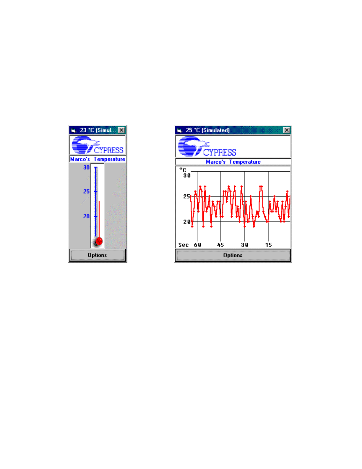
Changing the display st yle from conventional thermometer display to a history of
temperature
The Thermometer application will display either the current temper ature using a conventional
thermometer symbol or a histor y of t he temper ature recorded during the last 64 sample periods
(See
Figure C1
).
Conventional
Thermometer Display
Figure C1
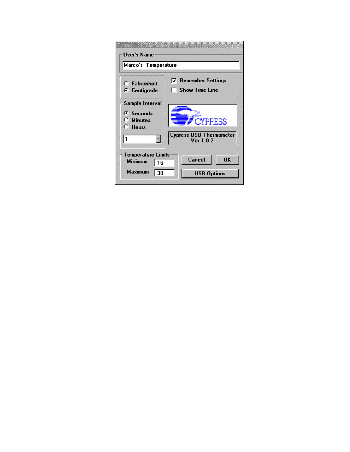
To change the display style, click on the “Options” box in either the conventi onal thermometer
display or the temper ature history display. Checking the “Show Tim e Line” box will sel ect the
temperature history display. “Unchecking” the “Show Time Line” box will sel ec t t he c onv entional
thermometer displ ay . Click on the “OK” box to complete your selection. (see
Cypress Semiconductor Ver 0.993
Page 7
Temperature Hi story
Display
Figure C2
).
Artisan Technology Group - Quality Instrumentation ... Guaranteed | (888) 88-SOURCE | www.artisantg.com
Page 9
Cypress CY3640 USB Starter Ki t
User’s Guide
Figure C2
Changing the maximum and minimum temperature value displayed
The Thermometer application can display temperatures between 0ºC and 70ºC. (32ºF and 158ºF)
The user may set the temperatur e r ange display on the Options screen by entering the desired
value in the appropriate “Temperature Limits” text box.
Changing the user’s name
The user may change the headi ng, which appear s at the top of the temperature display.
This is done on the Options screen by changing the text in the “User’s Name” text box.
Changing the display mod e from Centig rade to Fahrenheit
The Thermometer application can display temperature in either Centigrade or Fahrenheit.
The display mode is selected in the Options screen by selecting either the Fahrenheit or the
Centigrade radio buttons box.
Changing the time between temperature sample periods
The Thermometer application can sample the temperature at a variabl e rate determined by the
user.
The user sets the sample rat e on the Options screen by selec ting the appropriate options in the
“Sample Interv al” ar ea. Sam ple intervals may be chosen between one per second to one every
30 hours.
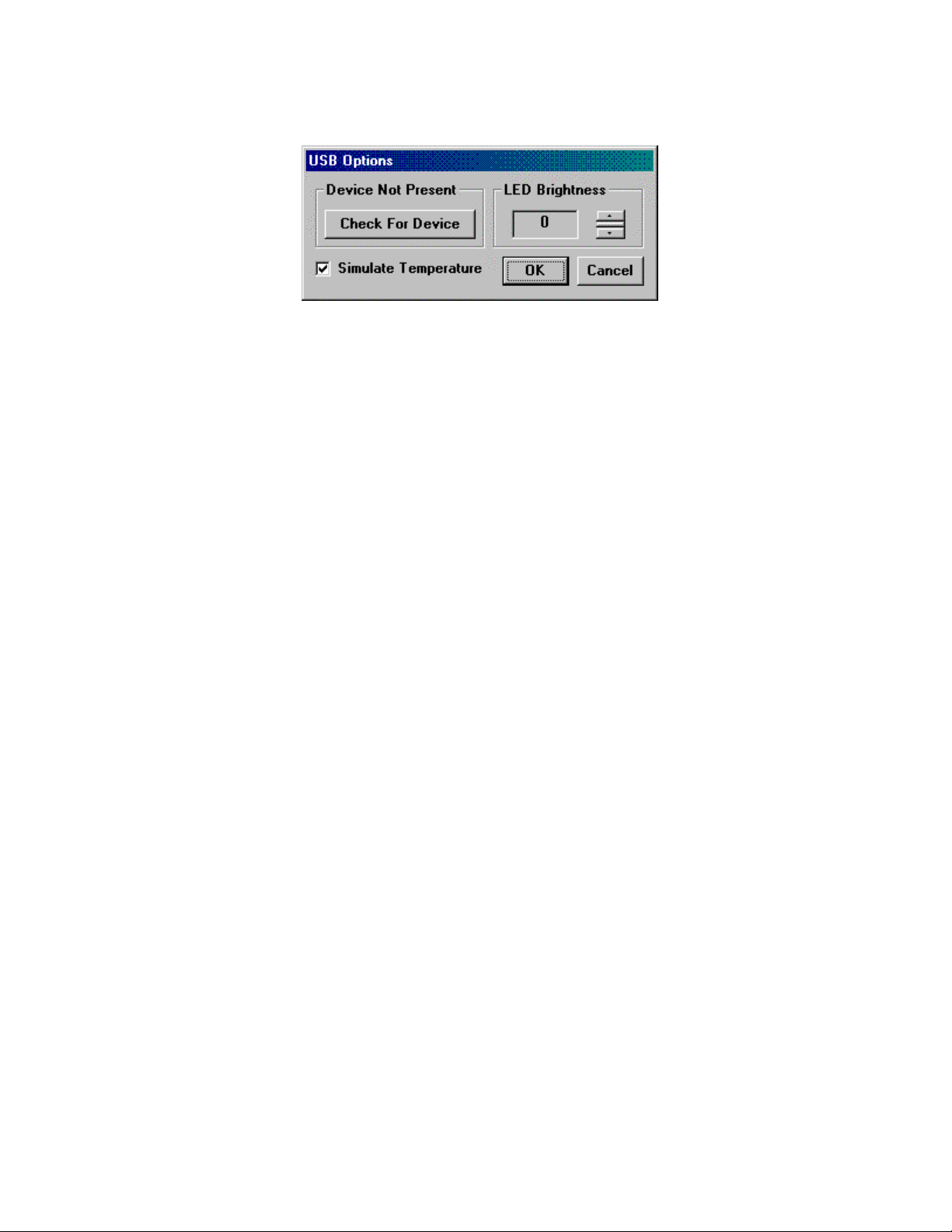
Simulating temperature measurements
The Temperatur e displ ay pr ogr am all ows you to simulate temperature readings instead of
actually measuring them.
You can select this by clic ki ng on the “US B Opti ons” box. The “USB Options” screen will be
displayed. (S ee
Figure C3
)
Checking the “Simulate Temperature” box will cause the thermomet er to enter a test mode in
which a series of random temper ature readings will be displayed.
Cypress Semiconductor Ver 0.993
Page 8
Artisan Technology Group - Quality Instrumentation ... Guaranteed | (888) 88-SOURCE | www.artisantg.com
Page 10
Cypress CY3640 USB Starter Ki t
User’s Guide
Figure C3
Testing to see if a Cypress USB Thermo met er devi ce is present
If your Cypress USB Thermometer device is plugged in to the USB and you cannot get
temperature measurements, you may try to connect to it by clicking the “Check For Device”
button on the USB Options screen (See
Figure C3
). This screen is available by clicking the “USB
Options” button on t he Opti ons screen.
The text above the button will indicate whether the Thermometer application is connected to the
Cypress USB Thermometer device t hr ough the device driver. If it is, the “Check For Device”
button will be disabled.
Changing the brightness of the Enumerated LED on the Cypress USB Thermometer device
The brightness of the E num er ation LED on the Cypress USB Thermometer PC board may be set
to one of sixteen lev els.
The user can set the brightness level desired on the “US B Options” screen by changing the value
of the “LED Brightness” box ( S ee
Figure C3
). This screen is available by clicking the “USB
Options” button on t he Opti ons screen.
The values may be set from zero to fif teen, with z er o being the lowest setting.
Saving the current config uration of the Thermometer application
The user can choose to autom atically save the current configuration of the Therm om eter
applicati on when they ex it the program by checking the “Remember Settings” box. The
parameters saved inc lude:
Location on the desktop where the application screen will reside
•
User Name text
•
Centigrade or Fahrenheit mode
•
T em per ature history or conventional thermom eter display selection
•
Max imum and Minimum displayed temperature
•
T em per ature sample rate
•
Simulate temperature selection stat us
•
Cypress Semiconductor Ver 0.993
Page 9
Artisan Technology Group - Quality Instrumentation ... Guaranteed | (888) 88-SOURCE | www.artisantg.com
Page 11

Cypress CY3640 USB Starter Ki t
User’s Guide
E. About the Cypress CY3640 USB Starter Kit
Overview
The Cypress CY3640 USB Start er Kit incl udes a fully functional USB thermometer devic e, a
Windows95 thermometer application, and a USB Thermometer device driver. Together, these
components allow the user to m easure and display temperatures between 0ºC and 70ºC to an
accuracy of ±1ºC.
In addition to bei ng a useful US B device, Cypress has designed t he US B S tarter Kit to serve as
an easily customizable platform for USB device development using the Cy pr ess CY7C63X0X
family of USB contr oller s.
Features
The CY3640 has the following features:
The Cypress USB Controller is socketed i n a 20- pin socket
It may be removed, reprogrammed, and replaced for easy development of new assembly
code.
Cypress has supplied a bread board ar ea ( sea of holes)
This area will accept wir e wrap pi ns and wire wrap sockets. This area will make it easy to
develop additi onal logic on-board.
A connector for use with standard 40-pin flat-cable connectors has been prov ided.
All signals fr om the Cypress USB Controller, which are useful for the developm ent of exter nal
logic, are available at pins on the connector. The signal names are label ed on the t op lay er of
the board. Pin numbers on the c onnec tor are labeled on both the top and bottom layers of the
board to make it easy to wire to the connec tor.
An identical set of signal vias is placed adjacent to the connector for easy wiri ng to the
signals.
Connections to ext er nal power source
There is a location f or an ext er nal power supply c onnec tor, but the connector is not suppli ed
with the kit. Indiv idual labeled locations for Vss, USB Vbus (the positive supply of the USB ),
and External Vcc are provided on either side of the sea of holes.
LED indicators (Power and Enumeration)
The CY3640 includes two LEDs: a red and a green one. A s conf igured when the CY3640 is
shipped from the f actor y, the LEDs are used to indicate that power is applied and that the
USB host has enumerated t he Cy pr ess USB Thermometer device, respectively.
The anode of each LED is connected to the USB Vbus (positive supply) through a current
limiting resistor . The cathode of each device is connected to three places to allow you to
reconfigure them for your own purposes: a j um per , a pin on the 40-pin connector, and a hole
for installi ng a wir e wrap pi n.
The Power LED
The Power LED (as shipped from Cypress) is used t o indicate that power (Vbus) from the
USB has been applied. It is connected through a jumper (JP1) and a current limiting resistor
(R4) directl y between Vbus and Vss, and will be lit whenever power is applied through the
USB. The user may remove JP1 if desired.
Cypress Semiconductor Ver 0.993
Page 10
Artisan Technology Group - Quality Instrumentation ... Guaranteed | (888) 88-SOURCE | www.artisantg.com
Page 12

Cypress CY3640 USB Starter Ki t
User’s Guide
The cathode of thi s LED is also connected to a pin on the 40- pin c onnec tor (pin 8) and to an
adjacent hol e that may be used to install a wire wrap pin. This allows the user to remove the
factory-installed jumper to Vss and use the LED for their own purposes.
Although it may be convenient to know when the USB i s appl yi ng power, dur ing
Note:
development. The f act that JP1 is left c onnec ted to Vss makes the dev ic e not strictly
compatible wit h the USB specification, because it will draw approxim ately 20 mA whenever it
is connected. T he USB specification limits power prior to the device being configured to 500
µA.
The Enumeration LED
The Enumeration LED ( as shipped f r om Cy pr ess) is used to i ndic ate that the USB
Thermometer dev ic e has been enumerated. The cathode of the LED is connected to P13
through a jumper (JP2) which controls its path to Vss.
The cathode of thi s LED is also connected to a pin on the 40- pin c onnec tor (pin 10) and to an
adjacent hol e that may be used to install a wire wrap pin. This allows the user to remove the
jumper to P13 and use the LED for their own purposes.
The switch (SW1)
SW1 (as shipped) on the Cypress USB Thermometer is used to select whether the
Thermometer Windows application displays the temperatur e in Centigrade or Fahrenheit. It is
a momentary SPST.
One pole of the switch is connected to Vss. The other pole is connected to Vcc (Vbus)
through R4, to a pin on the 40-pin connector (pin 6), to an adjacent hole that may be used for
installi ng a wire wrap pin, as well as to the GPIO P 12 of t he USB controller through a jumper
JP3. This allows the user to remove the jumper to P12 and use SW1 for their own purposes.
The breadboard area
Sea of holes
Cypress has provided an area that will ac c ept wire wrap pi ns and wire wrap sockets for
development of l ogic and functionality on the board.
USB Vbus (Vcc) and Vss connections
We have provided loc ations for connect ing power and ground from the USB to your bread
board area. These locations will ac c ept wire wrap pins.
External Vcc connect ions
If you need to power your breadboard with an external supply, a connector site (P 1) i s
supplied for t hat purpose. Two capacitor locations are also provi ded adjac ent to the
connector for by pass. C6 i s a bul k bypass and C7 is f or high frequenc y . These capacitors are
not populated wit h the CY3640 as shipped, and y ou shoul d use components appropriate to
your needs.
The External Vcc supply is brought to the bread board area and connected to three locations
labeled (oddly enough) Ext. Vcc. You may insert wire wrap pins in these locations to rout e to
your breadboard area.
The temperatur e sensor (U2)
The temperatur e sensor dev ic e is socketed so i t can be removed if you need to use the
associated pins on the Cy pr ess USB Contr oller for other logic on your breadboard.
Ferrite bead locati ons
If noise is a problem in your envir onm ent, locations for two ferrite beads (FB1 and FB2) have
been provided: one f or the V cc supply from the USB and one for the Ground return to the
Cypress Semiconductor Ver 0.993
Page 11
Artisan Technology Group - Quality Instrumentation ... Guaranteed | (888) 88-SOURCE | www.artisantg.com
Page 13

Cypress CY3640 USB Starter Ki t
User’s Guide
USB. These beads should not be nec essarily and are provided for exceptional noisy
environments.
The locations are shorted by a trac e on the bottom layer of the PC board. If you desire to use
ferrite beads, you should c ut the traces and install beads suitable to your needs.
Other items of interest
Bulk capacit or bl eeder r esi stor ( R5)
A resistor is provided to bleed off t he c har ge stor ed on the bulk capacitor . This is provided to
insure that charge is removed fr om the bulk c apaci tor and hence the board logic, within a
short period aft er the devic e is unpl ugged from the USB.
USB connector
A “B” receptacl e has been provided on the board so a detachable A/B cable can be used with
the device.
A footprint for an in-li ne c onnec tor (P2) to a permanently attached USB cable has been
provided if you need to have a non- r em ov able US B cable.
Cypress Semiconductor Ver 0.993
Page 12
Artisan Technology Group - Quality Instrumentation ... Guaranteed | (888) 88-SOURCE | www.artisantg.com
Page 14

Cypress CY3640 USB Starter Ki t
User’s Guide
F. Changing the functionality of the Cypress CY3640 USB
Starter Kit
The CY3640 USB Starter Kit is designed t o allow you to add or change its functionality in a
variety of ways in order to meet your needs.
You may easily:
Add logic to the board itself
•
Change t he functionality of the on-board LEDs and the switc h
•
Change t he pr ogr am stored inside the Cypress USB Controller
•
Use an ex ternal power source
•
T ak e si gnals off of or bring signals onto t he boar d
•
Changing the program in your devi ce
You can write your own code for y our Cypress USB Contr oller.
The easiest way is to use the code provided as a base and change only those parts which are
specific to your product.
The routines you will need to focus your changes on are in the file “USB.ASM”. They are
Main
•
SetConfig
•
1024usec IRQ handling
•
Vendor S pec ific Setup Commands
•
Assembling the code for your device
You can assemble your code for the Cypress USB Controller with CYASM, Cypress’ assembler.
See the Cypress CYASM documentation. Both CYASM and its documentation are included in the
USB Starter Kit CD-ROM.
Programming your device
After you have written and assembled your own USB controller firmware code, you can program
a new USB controller using the device programmer contained in the Cypress USB Starter Ki t.
Please note that the devic e pr ogr ammer only supports Cypress CY7C63X0X family of low-speed
USB controll er s, nam ely, CY 7C63000, CY7C63001, CY7C63100, CY7C63101, CY7C63200 and
CY7C63201. Its component s i nc lude:
a device programmer with a 32-pin DIP adapter
•
a f loppy disk with the programming software
•
a 9-pin serial cable
•
a wall power adapter
•
To program a new USB controller simply follow these steps:
Cypress Semiconductor Ver 0.993
Page 13
Artisan Technology Group - Quality Instrumentation ... Guaranteed | (888) 88-SOURCE | www.artisantg.com
Page 15

Cypress CY3640 USB Starter Ki t
User’s Guide
Connect the device programmer to your PC's serial port using the serial cable
•
T ur n it on by plugging the wall power adapter
•
Copy the programming software executabl e on the fl oppy disk t o your PC' s hard disk and
•
run it. At startup the software will detect the presence of the programmer connected to
the serial port and perform self-test
I nsert y our Cy pr ess USB cont r oller into the DIP adapter and choose the appropriat e
•
commands from the progr ammer software
The programming sof tware is actually quite simple; however, it provides all the necessary
functions to pr ogr am a USB contr oller, such as blank check, read, program, verify and security
fuse programming. The soft ware i s abl e to read and write .BIN and .HEX format fil es. To erase
the code programmed in t he windowed USB controller devices, use regular UV EPROM erasers
available on the market .
Adding yo ur own logic
See “Appendix D” for a description of the items that you may change to modify your design.
Cypress Semiconductor Ver 0.993
Page 14
Artisan Technology Group - Quality Instrumentation ... Guaranteed | (888) 88-SOURCE | www.artisantg.com
Page 16

Cypress CY3640 USB Starter Ki t
User’s Guide
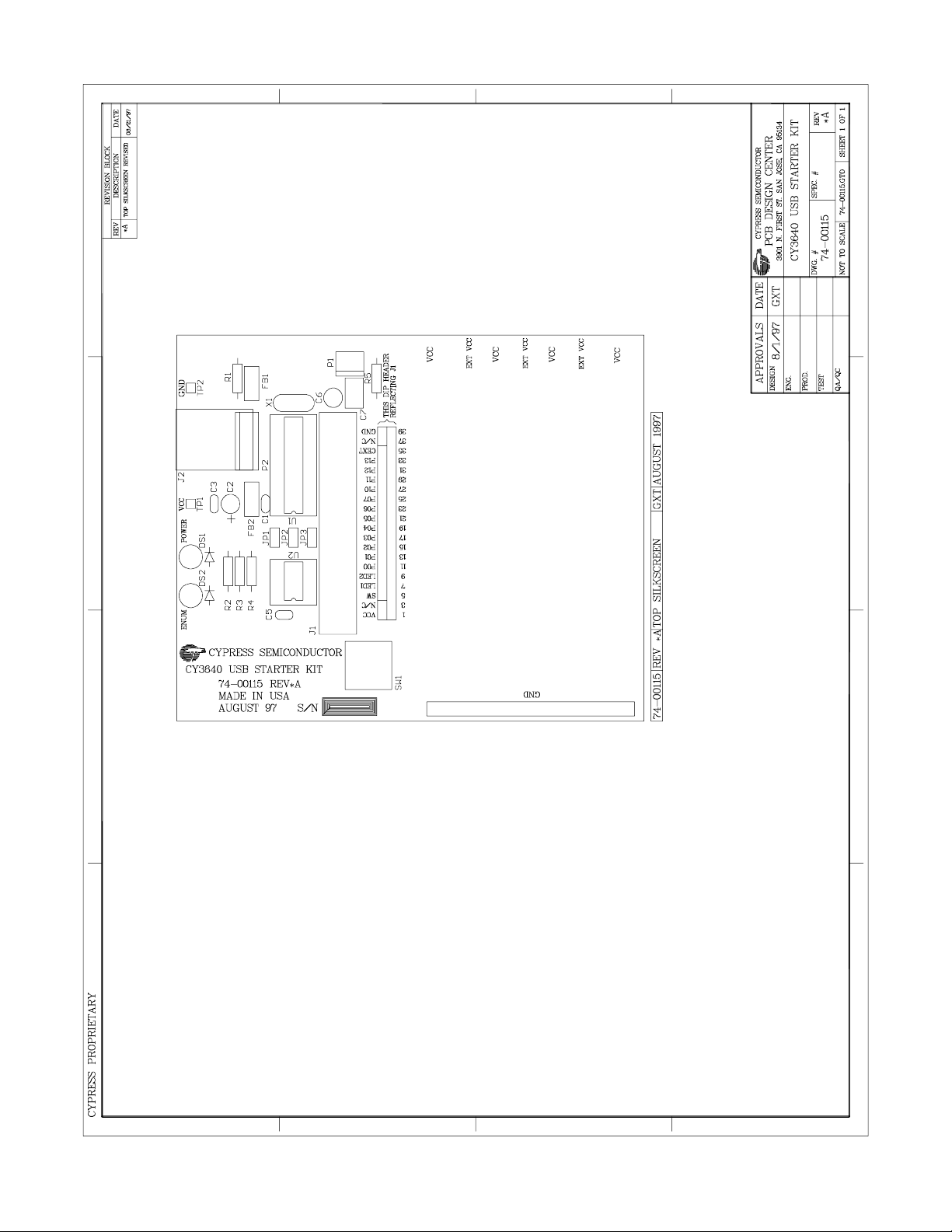
G. Cypress CY3640 USB Starter Kit Schematic
Bill of Materials
U1 Cypress CY7C63001 USB controller
U2 Dallas Semiconductor DS1623 temperature sensor
P1 2-pin header, polarized, 0.1" center, right angle. Not populated.
P2 5-pin header, polarized, 0.1" center, vertical. Not populated.
SW1 SPST, Momentary switch
DS1 20 mA, 2.2 Vdc Red LED, 0.1" center, 0.02 leads
DS2 20 mA, 2.2 Vdc Green LED, 0.1" center , 0. 02 leads
X1 6 MHz c er ami c resonator
JP1 2-pin header, 0. 1" cent er , wit h shunt
JP2 2-pin header, 0. 1" cent er , wit h shunt
JP3 3-pin header, 0. 1" cent er , wit h shunt
R1 7.5K Ohm, 1%, 1/8 W, carbon film resistor
R2 150 Ohm, 10%, 1/8 W, carbon film resistor
R3 150 Ohm, 10%, 1/8 W, carbon film r esi stor
R4 10K Ohm, 10%, 1/8 W, carbon film resi stor
R5 50K Ohm, 10%, 1/8 W, carbon film resi stor
C1 0.1
C2 4.7
C3 0.1
C5 0.1
C6 External Vcc Bulk capaci tor. Not populated
C7 External Vcc HF capaci tor. Not populated
J1 40-pin, boxed header, straight, 0.1" x 0.1" center
J2 USB "B" connector
FB1 Ferrite bead. Not populated
FB2 Ferrite bead. Not populated
F, 5%, Low ESL, 50 Vdc capacitor
µ
F, 10%, Tantalum, 25 Vdc capacitor
µ
F, 5%, Low ESL, 50 Vdc capacitor
µ
F, 5%, Low ESL, 50 Vdc capacitor
µ
The USB Starter Kit demo board layout and schematic are shown on the next two pages.
Cypress Semiconductor Ver 0.993
Page 15
Artisan Technology Group - Quality Instrumentation ... Guaranteed | (888) 88-SOURCE | www.artisantg.com
Page 17
Cypress CY3640 USB Starter Ki t
User’s Guide
Cypress Semiconductor Ver 0.993
Page 16
Page 16
Artisan Technology Group - Quality Instrumentation ... Guaranteed | (888) 88-SOURCE | www.artisantg.com
Page 18

Cypress CY3640 USB Starter Ki t
User’s Guide
Cypress Semiconductor Ver 0.993
Artisan Technology Group - Quality Instrumentation ... Guaranteed | (888) 88-SOURCE | www.artisantg.com
Page 17
Page 17
Page 19

Cypress CY3640 USB Starter Ki t
User’s Guide
H. Cypress USB Controller micro code (Assembly)
USB.ASM
;; USB_20.ASM
;*******************************************************************************
;
; *******************************************************************************
;
; Target:
; Cypress 7C63000 8bit RISC microcontroller with 1.5Mbps USB serial interface
; Dallas 1623: High Resolution Temperature Measurement Sensor
; Overview
; There are four main sub-systems: USB, Thermometer, LED, and Button.
; The system is started in the main() routine at reset. This routine
; initializes the USB variables, the IO ports, the Thermometer logic,
; and the data space. All USB communication occurs on an interrupt basis.
; First, Main() loops waiting for a USB reset.
; After receiving a USB reset, Main() enables the Endpoint 0 interrupt and
; loops waiting for Setups which ultimately will the result in the device
; being enumerated.
; Once the device has been enumerated on the USB, the main loop waits 10ms,
; polls the thermometer, updates the LED, and initializes end point 1 if
; appropriate.
; USB
; Endpoint 0 is used to support Control Transfers and vendor specific
; requests. End point 1 is also available for interrupt requests handling
; small packets of data (good for mouse, joystick, keyboard, thermometer, etc.).
; However, it is not used in this code.
; Each control transfer interrupts the processor and the subsequent routines
; services it.
; Thermometer
; A simple 9-bit temperature value is read from the thermometer every 10ms. At
; startup, the thermometer is initialized and placed into a continuous mode
; storing internally the current temperature. Thereafter, the temperature is
; read synchronously and returned into the USB end point one FIFO buffer.
; LED
; The LED is controlled by P13. When P13 goes low, the LED is turned on.
; The LED indicates the status of the USB connection. Once this device has
; "logically" been enumerated and configured to run on the serial bus, the LED
; is illuminated. The LED supports adjusting the brightness intensity by first
; setting the new brightens value (default: FFh = High) and then setting the
; brightness update field.
; Button
; A momentary push button is used to indicate that the application's
; Celsius/Fahrenheit display mode should be toggled.
; With each GetTemperature request, a value is sent indicating whether the
; button has been pushed.
; The GPIO interrupt is triggered by pushing the button causing its
; level to change from High to Low. A 100ms debounce was added to control the
; erroneous re-occurrence of this logical state change for a period. The
; 1024ms timer decrements the debounce to zero, re-enabling the button if at the
; end of the time out it has returned High.
;
; Port Usage
; P0.0 - Thermometer Data (input/output)
; .1 - Thermometer Clock (output)
; .2 - Thermometer Reset (output)
; .3 ; .4 ; .5 ; .6 ; .7 ; P1.0 ; .1 -
Cypress Semiconductor Ver 0.993
Page 18
Artisan Technology Group - Quality Instrumentation ... Guaranteed | (888) 88-SOURCE | www.artisantg.com
Page 20

Cypress CY3640 USB Starter Ki t
User’s Guide
; .2 - Button (0=pushed) (input)
; .3 - LED (0=on) (output)
;
;*******************************************************************************
;//$PAGE
; Directives
FillROM 0
; Microprocessor definitions
include "63x0x.inc"
;*************************************************
; Data Segment (RAM)
;*************************************************
; Program Stack
gbSysProgramStack :equ 00h ; [00h-1Fh] Stack 0x20h
gbSysDataStack :equ 50h ; [50h-6Fh] Stack 0x20h
gbSysFIFO :equ 70h ; [70h-7Fh] EP0 and EP1 FIFO's
; Global Interrupt
gbSysInterruptMask :equ 20h ; Holds the current interrupt mask
; System tickers
gbSysTick1024us :equ 22h ; # of 1mSec ticks
gbSysTick1024usRoll :equ 24h ; # of 256mSec ticks
; USB management data
gbUSBValidRqsts :equ 25h ; Count of USB recognized requests
; Used during debug
gbUSBSendSequence :equ 26h ; Buffer send data 0/1 line
gbUSBSendBytes :equ 27h ; Buffer bytes left to send
gbUSBSendBuffer :equ 28h ; Offset into current buffer
gbSuspendCount :equ 30h ; # of msec bus has been IDLE
; General
gbSysEnumerated :equ 29h ; Device is enumerated
; LED management
gbLEDBrightnessUpdate :equ 2Bh ; Semaphore to reset brightness
gbLEDBrightness :equ 2Ch ; Current brightness
LED_ON :equ 08h ; P13 is used to indicate Enumeration
; Button management
gbButtonDebounce :equ 2Dh ; Debounce count down value
gbButtonPushed :equ 7Ah ; USBEndP1FIFO +2 (toggles if button was clicked)
Button_Pin :equ 04h ; Pin the switch is on, P12
;//$PAGE
;*************************************************
; Code Segment (ROM)
;*************************************************
; Vector Table
org 00h
jmp main ; Reset of some type
jmp SysUnUsed ; 128us timer (not used)
jmp SysTimer1024usEvent ; 1024us timer
jmp USBEndPoint0Event ; EP0
jmp SysUnUsed ; EP1 (not used)
jmp SysUnUsed ; Reserved
jmp SysGPIOEvent ; Button
jmp SysUnUsed ; CExt (not used)
;*************************************************
; Unused event
; Do nothing, restore machine to prior state
Cypress Semiconductor Ver 0.993
Page 19
Artisan Technology Group - Quality Instrumentation ... Guaranteed | (888) 88-SOURCE | www.artisantg.com
Page 21

Cypress CY3640 USB Starter Ki t
User’s Guide
;*************************************************
SysUnUsed:
push a
mov a,[gbSysInterruptMask]
ipret SysInterrupt
;//$PAGE
;*******************************************************************************
; main()
; @func Entry point after PowerOn, WatchDog timeout or WakeUp from sleeping.
; @comm Never returns
;*******************************************************************************
main:
; This portion of Main is only executed after a RESET (Power-On or USB)
; Setup data stack in high order RAM, just below EP0 FIFO
; It will grow down from here
mov a,70h ; USBEndP0FIFO
swap a,dsp
; Initialize both Ports high
mov a,FFh
iowr SysPort0 ; Port 0 Data reg
iowr SysPort1 ; Port 1 Data reg
; 1 on P13 is needed to make sure enumerate LED is off
; 1 on any port that needs to be an input
; Enable Pullups (0=enable)
mov a,0
iowr SysPort0PullUp
mov a,Button_Pin
iowr SysPort1PullUp ; 1 on P12 is needed to make sure GPIO interrupt
; occurs on LOW to HIGH transistion. This
; disables it's pull up
; Enable or disable interrupts on appropriate pins
mov a,0
iowr SysPort0IntEnable ; All pins irq's are disabled on Port 0
mov a,Button_Pin
iowr SysPort1IntEnable ; Enable P12, the button pin.
; No interrupts will occur until the device
; is enumerated. Then GPIO's will be enabled and
; we will allow P12 to generate interrupts
; Initialize timers
mov a,0
mov [gbSysTick1024us],a
mov [gbSysTick1024usRoll],a
; Initialize USB variables
mov a,0
mov [gbUSBValidRqsts],a ; No valid requests yet
mov [gbUSBSendSequence],a ; Start with a 0
mov [gbSysEnumerated],a ; Not enumerated
; Initialize LED
mov a,1 ; flag it for an update
mov [gbLEDBrightnessUpdate],a
mov a,FFh ; set for maximum brightness
mov [gbLEDBrightness],a
; Initialized Button
mov a,0
mov [gbButtonPushed],a ; Initial state of 0, no button pushed
; Initialize variables
mov a,0
mov [gbUSBSendBytes],a ; No bytes to send in FIFO buffers
mov [gbSuspendCount],a ; Reset bus activity to 0
mov [gbButtonDebounce],a ; We are not debouncing
; Set interrupt mask
mov a,SysIntTimer1024us | SysIntUSBEndP0
Cypress Semiconductor Ver 0.993
Page 20
Artisan Technology Group - Quality Instrumentation ... Guaranteed | (888) 88-SOURCE | www.artisantg.com
Page 22

Cypress CY3640 USB Starter Ki t
User’s Guide
mov [gbSysInterruptMask],a
;*********************************************
MainLoop:
; Enable interrupts to current mask
mov a,[gbSysInterruptMask]
iowr SysInterrupt
;*************************
; do nothing until we are enumerated
mov a,0
cmp a,[gbSysEnumerated]
jz MainLoop ; Not enumerated, loop
; Ah! We're enumerated, lets do the rest of the loop
;*************************
; Write a 0 to the LED on P13 to turn it on
mov a,~(LED_ON)
iowr SysPort1
; Wait 10 milliseconds
mov a,10
call SysDelayMS
;*************************
; Read temperature
call ThermReadTemperature
;*************************
; Update brightness?
; mov a,0
cmp a,[gbLEDBrightnessUpdate]
jz MainLoopNoLEDUpdate ; No, branch
; Yes, update the LED brightness
; Reset the LED update flag
; mov a,0h
mov [gbLEDBrightnessUpdate],a
; Set new brightness
mov a,[gbLEDBrightness]
iowr SysPort1ISinkPin3
; Fall through to here in any case
MainLoopNoLEDUpdate:
; Loop
jmp MainLoop
;*********************************************
halt
; Oops! We should never get here
;********************************************************
; SysTimer1024usEvent()
; @func Timer interrupt event ocurring every 1.024 mSec
; using 6Mhz crystal.
;********************************************************
SysTimer1024usEvent:
; Save accumulator
push a
; Clear watchdog timer
; Clearing it here effectively disables the timer
iowr SysWatchDog
; Keep track of length of any IDLE conditions (No bus activity)
Cypress Semiconductor Ver 0.993
Page 21
Artisan Technology Group - Quality Instrumentation ... Guaranteed | (888) 88-SOURCE | www.artisantg.com
Page 23

Cypress CY3640 USB Starter Ki t
User’s Guide
iord USBControl ; Read the USB Status and Control Reg
and a,01h ; Check bit 0
cmp a,0h
jz Inc_Counter ; Hmm! No activity. Branch and keep track of it.
iord USBControl ; Ah! There was activity,
; clear the bus activity bit
and a,0feh
iowr USBControl
mov a,0 ; Clear the suspend counter
mov [gbSuspendCount],a
jmp Suspend_End
Inc_Counter: ; Monitor the IDLE count
mov a,[gbSuspendCount] ; Get # of mSec we have been IDLE
inc a ; Increment the count
mov [gbSuspendCount],a
cmp a,03h ; Has it been 3msec yet?
jnz Suspend_End ; Not yet, branch
mov a,0h ; Yes, clear the suspend counter
mov [gbSuspendCount],a
iord SysStatus
or a,08h ; Set the suspend bit to cause a suspend
iowr SysStatus ; We will enter the suspend state during
; the next instruction.
Suspend_End:
; Increment the 1024 usec counter and check for rollover
inc [gbSysTick1024us]
jnz STimerNo1024usRoll ; No
; Clear rollover
mov a,0
mov [gbSysTick1024usRoll],a
STimerNo1024usRoll:
; Are we counting down a button debounce
mov a,0
cmp a,[gbButtonDebounce]
jz STimerNoDebounce ; Not debouncing, branch
; Yes, we're debouncing. Let's see if we are timed out.
dec [gbButtonDebounce]
mov a,0
cmp a,[gbButtonDebounce]
; has debounce timed out?
jnz STimerNoDebounce ; No, still debouncing, branch.
; The debounce timer has timed out
; check if the button pin is at a 1. If not, the button is either still
; bouncing or still pushed
iord SysPort1 ; check the port the button is on
and a,Button_Pin ; check the pin
jnz STimerDebounceOver ; branch if it is not pushed ; mrr
; Reset debounce since the button is not yet released or is bouncing
mov a,100
mov [gbButtonDebounce],a
jnz STimerNoDebounce ; continue waiting for debounce to end
STimerDebounceOver:
; it's really ready!
; Toggle the button state flag to let the Windows app know that
; the button has been pushed.
mov a,1
xor [gbButtonPushed],a
; Debounce must be over
STimerNoDebounce:
; Enable interrupts and return
mov a,[gbSysInterruptMask]
Cypress Semiconductor Ver 0.993
Page 22
Artisan Technology Group - Quality Instrumentation ... Guaranteed | (888) 88-SOURCE | www.artisantg.com
Page 24

Cypress CY3640 USB Starter Ki t
User’s Guide
ipret SysInterrupt
;//$PAGE
;********************************************************
; SysGPIOEvent()
; @func General purpose port event
; @comm Which pin?
;********************************************************
SysGPIOEvent:
; Save accumulator
push a
; Reset debounce any time we are here
mov a,100
mov [gbButtonDebounce],a
SysGPIOButtonDebouncing:
; Enable interrupts and return
mov a,[gbSysInterruptMask]
ipret SysInterrupt
;*******************************************************************************
;
; This section of code responds to activity on End Point 0 and determines
; what needs to be done.
;
;*******************************************************************************
;//$PAGE
;********************************************************
; USBEndPoint0Event()
; @func End Point zero USB event.
; @comm Default end point.
;********************************************************
USBEndPoint0Event:
; This code checks to see what type of packet was received
; (Setup, Out, or In) and jumps to the correct routine to decode the
; specifics. After the code to which the jump points is through, it jumps
; back to USBEventEP0End.
; Save accumulator
push a
; Is this a SETUP packet?
iord USBEndP0RxStatus
and a,USBEndP0RxSetup ; Check the setup bit
jnz USBEventEP0_SETUP ; Yes it's a setup, branch
; Not a setup, is it an OUT packet?
;iord USBEndP0RxStatus
;and a,USBEndP0RxOut
;jnz USBEventEP0_OUT
; Not an OUT packet, is it an IN packet?
;iord USBEndP0RxStatus
;and a,USBEndP0RxIn
;jnz USBEventEP0_IN
USBEventEP0_IN:
USBEventEP0_OUT:
USBEventEP0End:
; OK. We're done with the packet.
; Let's enable interrupts and return
mov a,[gbSysInterruptMask]
ipret SysInterrupt ; done with EP0 irq service routine
USBEventEP0Stall:
Cypress Semiconductor Ver 0.993
Page 23
Artisan Technology Group - Quality Instrumentation ... Guaranteed | (888) 88-SOURCE | www.artisantg.com
Page 25

Cypress CY3640 USB Starter Ki t
User’s Guide
; Stall any subsequent IN's or OUT's until the
; stall bit (bit 5) is cleard by an I/O write to
; the USB End Point 0 TX Configuration Register (0x10)
; or any SETUP is received.
iord USBEndP0TxConfig
or a,USBEndP0TxStall
iowr USBEndP0TxConfig
; OK. We've set the stall condition for Endpoint 0.
; Now let's complete the routine.
jmp USBEventEP0End
;*******************************************************************************
;
; We know we have received a Setup token. Now we need to parse it to
; determine what command it is.
;
;*******************************************************************************
;//$PAGE
;*******************************************************************************
; USBEventEP0_SETUP()
; @func End point event SETUP packet handler.
; @devnote Runs in interrupt enabled context.
;********************************************************
USBEventEP0_SETUP:
; Well, we have a SETUP packet. Let's find out what to do.
mov A,[gbSysInterruptMask]
iowr SysInterrupt
; If we are here and are and we are processing a previous Setup,
; we need to abort the processing of the previous Setup
mov a,0 ; Clear any indication that we have bytes left to transfer
mov [gbUSBSendBytes],a
; Clear EP0 RxReg (including the Setup flag)
; The Data toggle bit remains unchanged, however.
mov a,0
iowr USBEndP0RxStatus
;*********************************************
; Setup Event
;*********************************************
; Check the request type and branch to the correct location to handle it.
mov a,[USBEndP0FIFO_0]
USBEventEP0SetupTargetDeviceOUT:
; Target Device?
cmp a,USBRqstTargetDevice
jz USBEventEP0SetupIsSetAddress ; Yes
USBEventEP0SetupTargetInterfaceOUT:
cmp a,USBRqstTargetInterface
jz USBEventEP0Stall ; Yes. Oops! We don't have an interface.
USBEventEP0SetupTargetEndpointOUT:
cmp a,USBRqstTargetEndPoint
jz USBEventEP0Stall ; Yes
USBEventEP0SetupTargetDeviceIN:
cmp a,USBRqstTargetDevice | USBRqstTypeDirection
jz USBEventEP0SetupGetDescriptor ; Yes
USBEventEP0SetupTargetInterfaceIN:
cmp a,USBRqstTargetInterface | USBRqstTypeDirection
jz USBEventEP0Stall ; Yes Oops! We don't have an interface.
USBEventEP0SetupTargetEndpointIN:
cmp a,USBRqstTargetEndPoint | USBRqstTypeDirection
Cypress Semiconductor Ver 0.993
Page 24
Artisan Technology Group - Quality Instrumentation ... Guaranteed | (888) 88-SOURCE | www.artisantg.com
Page 26

Cypress CY3640 USB Starter Ki t
User’s Guide
jz USBEventEP0Stall ; Yes
; Vendor specific commands
USBEventEP0SetupTargetVendorIN_OUT:
; Check request (IN packet OK, OUT packet ERR)
mov a,[USBEndP0FIFO_0]
and a,USBRqstTypeVendor | USBRqstTargetEndPoint | USBRqstTypeDirection
cmp a,USBRqstTypeVendor | USBRqstTargetEndPoint | USBRqstTypeDirection
jz USBEventEP0VendorRqst
; Unsupported request !!!
jmp USBEventEP0Stall ; Oops! We don't support whatever
; request was made.
;//$PAGE
;********************************************************
; USBEventEP0SetupIsSet()
; @func End point event SETUP to set address.
; @devnote Runs in interrupt enabled context.
;********************************************************
USBEventEP0SetupIsSetAddress:
; Set device address?
mov a,[USBRqstMessage]
cmp a,USBRqstSetAddress
jz USBEventEP0SetupSetAddress ; Yes
USBEventEP0SetupIsSetConfig:
; Set device configuration?
mov a,[USBEndP0FIFO_1]
cmp a,USBRqstSetConfiguration
jz USBEventEP0SetupSetConfig ; Yes
; Unsupported set request !!!
jmp USBEventEP0Stall ; No. Stall
;USBEventEP0SetupIsGetDescriptor:
mov a,[USBRqstMessage]
cmp a,USBRqstGetDescriptor
jz USBEventEP0SetupGetDescriptor ; Yes
; Unsupported get request !!!
jmp USBEventEP0Stall ; No
;********************************************************
; USBEventEP0SetupSetAddress()
; @func End point zero event SETUP to set address.
; @devnote Runs in interrupt enabled context.
; @comm
; The status token of the SetAddress is an IN. So, we send status manually.
;********************************************************
USBEventEP0SetupSetAddress:
; Send ACK
call USBSendACK
; Now that we have been acknowleged, we actually set the address.
; This is different from all other commands which execute first
; and then acknowlege (_________________)
; Remember this
inc [gbUSBValidRqsts]
; Set Address
mov a,[USBRqstWordValueLo]
iowr USBDeviceAddress
; Done
jmp USBEventEP0End
;********************************************************
Cypress Semiconductor Ver 0.993
Page 25
Artisan Technology Group - Quality Instrumentation ... Guaranteed | (888) 88-SOURCE | www.artisantg.com
Page 27

Cypress CY3640 USB Starter Ki t
User’s Guide
; USBEventEP0SetupSetConfig()
; @func End point zero event SETUP to Set Configuration.
; @devnote Runs in interrupt enabled context.
; 1
; set enumerated (gbSysEnumerated) state,
; enable GPIO (and EP1, if appropriate)
; Enable P0 and P1
; 0
; Reset enumerated (gbSysEnumerated) state,
; Turn off LED
; Reset variables
; Disable GPIO and EP1
; Disable dallas chip and P0 and P1
;********************************************************
USBEventEP0SetupSetConfig:
; Enumerated !
mov a,01h
mov [gbSysEnumerated],a
; Initialize thermometer
call ThermInitialize
; Enable button interrupt on port 1.
; Actually, this has already been done in main().
mov a,04h
iowr SysPort1IntEnable
; enable all appropriate irq's
mov a,SysIntTimer1024us | SysIntGPIO | SysIntUSBEndP0
mov [gbSysInterruptMask],a
; Send ACK
call USBSendACK
jmp USBEventEP0End
;//$PAGE
;********************************************************
; USBEventEP0SetupGetDescriptor()
; @func End point zero event SETUP to Get Descriptor.
; @devnote Runs in interrupt enabled context.
;********************************************************
USBEventEP0SetupGetDescriptor:
; Get descriptor type
mov a,[USBRqstWordValueHi]
USBEventEP0SetupGetDescriptorDevice:
; Device Descriptor?
cmp a,USBDescriptorTypeDevice
jnz USBEventEP0SetupGetDescriptorConfig ; No
; Remember this
inc [gbUSBValidRqsts]
;*********************************************
; Get Device Descriptor Event
;*********************************************
; Descriptor pointer
mov a,(USBDeviceDescription -USBSendROMBufferBase)
mov [gbUSBSendBuffer],a
; Descriptor size
mov a,12h ;[USBDeviceDescription]
mov [gbUSBSendBytes],a
; Check request size field
call USBSendDescriptorCheckLength
; Send buffer
call USBSendROMBuffer
Cypress Semiconductor Ver 0.993
Page 26
Artisan Technology Group - Quality Instrumentation ... Guaranteed | (888) 88-SOURCE | www.artisantg.com
Page 28

Cypress CY3640 USB Starter Ki t
User’s Guide
jmp USBEventEP0End
USBEventEP0SetupGetDescriptorConfig:
; Configuration Descriptor?
cmp a,USBDescriptorTypeConfig
jnz USBEventEP0SetupGetDescriptorString ; No
; Remember this
inc [gbUSBValidRqsts]
;*********************************************
; Get Configuration Descriptor Event
;*********************************************
; Descriptor pointer
mov a,(USBConfigurationDescription -USBSendROMBufferBase)
mov [gbUSBSendBuffer],a
; Descriptor size
mov a,09h ;[USBConfigurationDescription]
add a,09h ;[USBInterfaceDescription]
add a,07h ;[USBEndPointDescriptionInt]
mov [gbUSBSendBytes],a
; Check request size field
call USBSendDescriptorCheckLength
; Send buffer
call USBSendROMBuffer
jmp USBEventEP0End
USBEventEP0SetupGetDescriptorString:
; Get String Descriptor?
cmp a,USBDescriptorTypeString
jnz USBEventEP0SetupGetDescriptorEnd ; No
;*********************************************
; Get String Descriptor Event
;*********************************************
; Get string descriptor index
mov a,[USBRqstWordValueLo]
USBEventEP0SetupGetDescriptorString0:
cmp a,0h
jnz USBEventEP0SetupGetDescriptorString1 ; No
;*********************************************
; Get String Language(s) Descriptor Event
;*********************************************
; Descriptor pointer
mov a,(USBStringLanguageDescription -USBSendROMBufferBase)
mov [gbUSBSendBuffer],a
; Descriptor size
mov a,4h ;[USBStringLanguageDescription]
mov [gbUSBSendBytes],a
; Check request size field
call USBSendDescriptorCheckLength
; Send buffer
call USBSendROMBuffer
jmp USBEventEP0End
USBEventEP0SetupGetDescriptorString1:
cmp a,1
jnz USBEventEP0SetupGetDescriptorString2 ; No
;*********************************************
; Get String 1 Descriptor Event
;*********************************************
Cypress Semiconductor Ver 0.993
Page 27
Artisan Technology Group - Quality Instrumentation ... Guaranteed | (888) 88-SOURCE | www.artisantg.com
Page 29

Cypress CY3640 USB Starter Ki t
User’s Guide
; Descriptor pointer
mov a,(USBStringDescription1 -USBSendROMBufferBase)
mov [gbUSBSendBuffer],a
; Descriptor size
mov a,10h ;[USBStringDescription1]
mov [gbUSBSendBytes],a
; Check request size field
call USBSendDescriptorCheckLength
; Send buffer
call USBSendROMBuffer
jmp USBEventEP0End
USBEventEP0SetupGetDescriptorString2:
cmp a,2
jnz USBEventEP0SetupGetDescriptorString3 ; No
;*********************************************
; Get String 2 Descriptor Event
;*********************************************
; Descriptor pointer
mov a,(USBStringDescription2 -USBSendROMBufferBase)
mov [gbUSBSendBuffer],a
; Descriptor size
mov a,18h ;[USBStringDescription2]
mov [gbUSBSendBytes],a
; Check request size field
call USBSendDescriptorCheckLength
; Send buffer
call USBSendROMBuffer
jmp USBEventEP0End
USBEventEP0SetupGetDescriptorString3:
cmp a,3
jnz USBEventEP0SetupGetDescriptorString4 ; No
;*********************************************
; Get String 3 Descriptor Event
;*********************************************
; Descriptor pointer
mov a,(USBStringDescription3 -USBSendROMBufferBase)
mov [gbUSBSendBuffer],a
; Descriptor size
mov a,24h ;[USBStringDescription3]
mov [gbUSBSendBytes],a
; Check request size field
call USBSendDescriptorCheckLength
; Send buffer
call USBSendROMBuffer
jmp USBEventEP0End
USBEventEP0SetupGetDescriptorString4:
cmp a,4
jnz USBEventEP0SetupGetDescriptorString5 ; No
;*********************************************
; Get String 4 Descriptor Event
;*********************************************
; Descriptor pointer
mov a,(USBStringDescription4 -USBSendROMBufferBase)
mov [gbUSBSendBuffer],a
; Descriptor size
Cypress Semiconductor Ver 0.993
Page 28
Artisan Technology Group - Quality Instrumentation ... Guaranteed | (888) 88-SOURCE | www.artisantg.com
Page 30

Cypress CY3640 USB Starter Ki t
User’s Guide
mov a,20h ;[USBStringDescription4]
mov [gbUSBSendBytes],a
; Check request size field
call USBSendDescriptorCheckLength
; Send buffer
call USBSendROMBuffer
jmp USBEventEP0End
USBEventEP0SetupGetDescriptorString5:
cmp a,5
jnz USBEventEP0SetupGetDescriptorEnd ; No
;*********************************************
; Get String 5 Descriptor Event
;*********************************************
; Descriptor pointer
mov a,(USBStringDescription5 -USBSendROMBufferBase)
mov [gbUSBSendBuffer],a
; Descriptor size
mov a,3Ch ;[USBStringDescription5]
mov [gbUSBSendBytes],a
; Check request size field
call USBSendDescriptorCheckLength
; Send buffer
call USBSendROMBuffer
jmp USBEventEP0End
USBEventEP0SetupGetDescriptorEnd:
; Unsupported Get request !!!
jmp USBEventEP0Stall
;//$PAGE
;********************************************************
; USBSendDescriptorCheckLength()
; @func Check and update send length for Get Descriptor
; requests on end point 0.
; @parm BYTE | gbUSBSendBytes | Number of bytes to send.
;********************************************************
USBSendDescriptorCheckLength:
; High byte set? (Assume <255 bytes)
mov a,[USBEndP0FIFO_7]
cmp a,0
jnz USBSendDescriptorCheckLengthEnd ; Yes
; Check size
mov a,[USBEndP0FIFO_6]
cmp a,[gbUSBSendBytes]
jz USBSendDescriptorCheckLengthEnd ; equal
jnc USBSendDescriptorCheckLengthEnd ; greater than
; New size
mov [gbUSBSendBytes],a
USBSendDescriptorCheckLengthEnd:
ret
;//$PAGE
;********************************************************
; USBSendROMBuffer()
; @func Send a number of ROM bytes on end point 0.
; @parm BYTE | gbUSBSendBytes | Number of bytes to send.
; @parm BYTE | gbUSBSendBuffer | Offset from ROM base
; of data to send.
; @comm assumes IN packets are ignored in the interrupt routine
; @devnote Enables interrupts
Cypress Semiconductor Ver 0.993
Page 29
Artisan Technology Group - Quality Instrumentation ... Guaranteed | (888) 88-SOURCE | www.artisantg.com
Page 31

Cypress CY3640 USB Starter Ki t
User’s Guide
;********************************************************
USBSendROMBuffer:
; Clear flag
mov a,0h
iowr USBEndP0RxStatus
; Enable interrupts
mov a,[gbSysInterruptMask]
and a,~SysIntUSBEndP0
iowr SysInterrupt
; Auto ACK OUT packet (This would be a Status Out)
mov a,USBControlAckStatusData
iowr USBControl
; Initialize sequence
mov a,0h
mov [gbUSBSendSequence],a
; Send count
mov a,[gbUSBSendBytes]
USendROMBufferLoop:
; One 8-byte chunk or less left?
cmp a,08h
jz USendROMBufferLoopDone ; exactly 8 bytes left, branch
jc USendROMBufferLoopDone ; less than 8 bytes left, branch
; more than 8 bytes left, fall through and loop
; until there are 8 bytes or less.
; Save count
push a
; Send 8 byte chunk
mov a,08h
mov [gbUSBSendBytes],a
call _USBSendROMBuffer
; Check for OUT packet cancelling send
iord USBEndP0RxStatus
and a,USBEndP0RxOut
; Restore count
pop a
; Handle exception: OUT packet cancel send
jnz USendROMBufferLoopExit ; Cancelled
; Save bytes left
sub a,08h
mov [gbUSBSendBytes],a
jmp USendROMBufferLoop
USendROMBufferLoopDone:
; Send last 8 or less bytes
call _USBSendROMBuffer
USendROMBufferLoopExit:
ret
;//$PAGE
;********************************************************
; _USBSendROMBuffer()
; @func Buffer and inialize USB send of up
; to 8 bytes of ROM data on end point 0.
; @comm affects gbUSBSendBytes & gbUSBSendBuffer
;********************************************************
_USBSendROMBuffer:
; Save x
Cypress Semiconductor Ver 0.993
Page 30
Artisan Technology Group - Quality Instrumentation ... Guaranteed | (888) 88-SOURCE | www.artisantg.com
Page 32

Cypress CY3640 USB Starter Ki t
User’s Guide
push x
; Initialize
mov x,0h
_USendROMBufferLoop:
; Any more?
mov a,0h
cmp a,[gbUSBSendBytes]
jz _USendROMBufferLoopDone ; No more
dec [gbUSBSendBytes]
; Move bytes to FIFO
mov a,[gbUSBSendBuffer]
index USBSendROMBufferBase
mov [x +USBEndP0FIFO],a
inc x
; Next byte
inc [gbUSBSendBuffer]
jmp _USendROMBufferLoop
_USendROMBufferLoopDone:
; Re-enable reception
mov a,0h
iowr USBEndP0RxStatus
; Toggle sequence
mov a,USBEndP0TxSequence
xor [gbUSBSendSequence],a
; Send bytes
push x
pop a
or a,[gbUSBSendSequence]
or a,USBEndP0TxRespond
iowr USBEndP0TxConfig
; The FIFO is loaded, go and wait untill it's read
call USBSendWaitForComplete
_USendROMBufferEnd:
; Restore and exit
pop x
ret
;//$PAGE
;********************************************************
; USBSendACK()
; func Respond to a "USB Status In" with a zero byte buffer with
; Sequence field set) on end point 0.
; Called by SetAddress and SetConfig commands
;********************************************************
USBSendACK:
; Status response to Status In is to send a zero byte packet
mov a,USBEndP0TxRespond | USBEndP0TxSequence
iowr USBEndP0TxConfig
; Enable interrupts
mov a,[gbSysInterruptMask]
iowr SysInterrupt
; Wait for send complete
jmp USBSendWaitForComplete
;********************************************************
; USBSendWaitForComplete()
; @func Wait for send to complete on end point 0.
;********************************************************
Cypress Semiconductor Ver 0.993
Page 31
Artisan Technology Group - Quality Instrumentation ... Guaranteed | (888) 88-SOURCE | www.artisantg.com
Page 33

Cypress CY3640 USB Starter Ki t
User’s Guide
; At some point, either the 0 data will be ACK'd or a SETUP
; will come in.
; Either event will cause the "Enable Respond
; to In Packets" to be reset, and we will fall out of the loop.
; In either case, an EP0 IRQ will be generated (5.9.2.2 in Cyp
; device spec) if EP0 irq is enabled.
USBSendWaitForComplete:
; Poll the send complete bit
; This will be reset when the data has been sent to the host
; and the host has ACK's, or the host has sent another SETUP
; which should terminate this activity in any case.
iord USBEndP0TxConfig
and a,USBEndP0TxRespond
jz USBSendWaitComplete
; Check for OUT packet cancelling send. A STATUS OUT should
; terminate any pending IN's. A Setup could also set the Out bit.
iord USBEndP0RxStatus
and a,USBEndP0RxOut
jnz USBSendWaitComplete ; Cancelled
; Keep waiting
jmp USBSendWaitForComplete
USBSendWaitComplete:
ret
;//$PAGE
;********************************************************
; USBEventEP0VendorRqst()
; @func Vendor request on end point zero.
; @devnote Runs in interrupt disabled context.
;********************************************************
USBEventEP0VendorRqst:
; Save it
push x
; Check Protocol
mov a,[USBEndP0FIFO_1]
USBEventEP0VendorRqstPing:
cmp a,0h
jnz USBEventEP0VendorRqstReadROM ; No
;*********************************************
; Ping Event
;*********************************************
jmp USBEventEP0VendorRqstFinish
USBEventEP0VendorRqstReadROM:
cmp a,01h
jnz USBEventEP0VendorRqstReadRAM ; No
;*********************************************
; Read ROM Event
;*********************************************
mov a,[USBEndP0FIFO_2]
index USBSendROMBufferBase
mov [USBEndP0FIFO_1],a
jmp USBEventEP0VendorRqstFinish
USBEventEP0VendorRqstReadRAM:
cmp a,02h
jnz USBEventEP0VendorRqstWriteRAM ; No
;*********************************************
; Read RAM Event
;*********************************************
Cypress Semiconductor Ver 0.993
Page 32
Artisan Technology Group - Quality Instrumentation ... Guaranteed | (888) 88-SOURCE | www.artisantg.com
Page 34

Cypress CY3640 USB Starter Ki t
User’s Guide
mov a,[USBEndP0FIFO_2]
push a
pop x
mov a,[x +0]
mov [USBEndP0FIFO_1],a
jmp USBEventEP0VendorRqstFinish
USBEventEP0VendorRqstWriteRAM:
cmp a,3
jnz USBEventEP0VendorRqstReadPort ; No
;*********************************************
; Write RAM Event
;*********************************************
mov a,[USBEndP0FIFO_2]
push a
pop x
mov a,[USBEndP0FIFO_4]
mov [x +0],a
jmp USBEventEP0VendorRqstFinish
USBEventEP0VendorRqstReadPort:
cmp a,04h
jnz USBEventEP0VendorRqstWritePort ; No
;*********************************************
; Read Port Event
;*********************************************
mov a,[USBEndP0FIFO_2]
cmp a,0h
jnz USBEventEP0VendorRqstReadPort1
USBEventEP0VendorRqstReadPort0:
iord SysPort0
jmp USBEventEP0VendorRqstReadPortsDone
USBEventEP0VendorRqstReadPort1:
iord SysPort1
;jmp USBEventEP0VendorRqstReadPortsDone ; redundant, but good practice
USBEventEP0VendorRqstReadPortsDone:
mov [USBEndP0FIFO_1],a
jmp USBEventEP0VendorRqstFinish
USBEventEP0VendorRqstWritePort:
cmp a,05h
jnz USBEventEP0Stall ; No
;*********************************************
; Write Port Event
;*********************************************
mov a,[USBEndP0FIFO_2]
cmp a,0
jnz USBEventEP0VendorRqstReadPort1
USBEventEP0VendorRqstWritePort0:
mov a,[USBEndP0FIFO_4]
iowr SysPort0
jmp USBEventEP0VendorRqstWritePortsDone
USBEventEP0VendorRqstWritePort1:
mov a,[USBEndP0FIFO_4]
iowr SysPort1
;jmp USBEventEP0VendorRqstWritePortsDone ; redundant, but good practice
USBEventEP0VendorRqstWritePortsDone:
;jmp USBEventEP0VendorRqstFinish ; redundant, but good practice
USBEventEP0VendorRqstFinish:
; Protocol ACK
Cypress Semiconductor Ver 0.993
Page 33
Artisan Technology Group - Quality Instrumentation ... Guaranteed | (888) 88-SOURCE | www.artisantg.com
Page 35

Cypress CY3640 USB Starter Ki t
User’s Guide
mov a,42h
mov [USBEndP0FIFO_0],a
; Auto ACK OUT packet
mov a,USBControlAckStatusData
iowr USBControl
; Send bytes as Data1
mov a,8
or a,USBEndP0TxSequence
or a,USBEndP0TxRespond
iowr USBEndP0TxConfig
;call USBSendWaitForComplete
; Restore it
pop x
; Return
jmp USBEventEP0End
;*****************************
;//$PAGE
include "ds1620a.asm"
;*****************************
;********************************************************
; SysDelayMS()
; @func Delay some number of milliseconds.
; @parm register | A | Number of milliseconds (0=65536).
; @comm Protects A and X registers.
;********************************************************
SysDelayMS:
; Save em'
push a
push x
SysDelayMSLoop:
; Save count
push a
; Delay 1ms = 10 * 100us
mov a,10
SysDelayMSLoopDelay:
; Save it
push a
; Delay 100us
mov a,100
call SysDelay
; Done?
pop a
dec a
jnz SysDelayMSLoopDelay
; Done?
pop a
dec a
jnz SysDelayMSLoop
; Restore em'
pop x
pop a
ret
;********************************************************
; SysDelay()
; @func Delay some number of microseconds.
Cypress Semiconductor Ver 0.993
Page 34
Artisan Technology Group - Quality Instrumentation ... Guaranteed | (888) 88-SOURCE | www.artisantg.com
Page 36

Cypress CY3640 USB Starter Ki t
User’s Guide
; @parm register | A | Number of microseconds (0=65536).
; @comm Protects A and X registers.
;********************************************************
SysDelay:
; Save em'
push a
push x
SysDelayLoop:
; Save count
push a
; Delay 1ms
nop ; 4 clock cycles (6Mhz or 166us cycle???)
nop
nop
nop
nop
nop
nop
nop
nop
nop
; Done?
pop a
dec a
jnz SysDelayLoop
; Restore em'
pop x
pop a
ret
;********************************************************
; Data Segment (ROM)
;********************************************************
USBSendROMBufferBase:
USBDeviceDescription:
db 12h ; Length
db 01h ; Type (1=device)
db 00h,01h ; Complies to USB Spec. v1.00
db 00h ; Class code (0=??)
db 00h ; SubClass code (0=??)
db 00h ; Protocol (0=none)(9.6.1)
db 08h ; Max. packet size for port0
db B4h,04h ; Vendor ID: (0x4B4=Cypress)
db 02h,00h ; Product ID (0x02=USB Thermometer)
db 09h,00h ; Device release v0.90
db 01h ; Manufacturer string descriptor index (0=none)
db 02h ; Product string descriptor index (0=none)
db 00h ; Serial number string descriptor index (0=none)
db 01h ; Number of possible configurations
USBDeviceDescriptionEnd:
;*************************************************
;
USBConfigurationDescription:
db 09h ; Length
db 02h ; Type (2=config)
db 19h,00h ; Total data length (1 config,1 interface,1 endpoints)
db 01h ; Interface supported (1=???)
db 01h ; Configuration value (1=???)
db 04h ; Confituration string descriptor index (0=none)
db 80h ; Configuration (80h=Bus powered)
db 32h ; Maximum power consumption in 2mA units
USBConfigurationDescriptionEnd:
;*************************************************
Cypress Semiconductor Ver 0.993
Page 35
Artisan Technology Group - Quality Instrumentation ... Guaranteed | (888) 88-SOURCE | www.artisantg.com
Page 37

Cypress CY3640 USB Starter Ki t
User’s Guide
;
USBInterfaceDescription:
db 09h ; Length
db 04h ; Type (4=interface)
db 00h ; Number of interfaces (0 based)
db 00h ; Alternate settings
db 01h ; Number of endpoints (1 based) (9.6.3)
db 00h ; Class code (0=non-specified,1=kb,2=mouse,3=joystick ???)
db 00h ; Subclass code (0=???)
db 00h ; Protocol code (0=non-specified)
db 05h ; Interface string index (0=non-specified, 1,2,3,...)
USBInterfaceDescriptionEnd:
;*************************************************
; Never used for EP0
USBEndPointDescriptionInt:
db 07h ; Length
db 05h ; Type (5=endpoint)
db 81h ; Address (EP#=1 | [0x80=IN, 0=OUT])
db 03h ; Attribute (0=control,1=isochronous,2=bulk,3=interrupt)
db 08h,00h ; Max packet size
db 0Ah ; Interval (10 ms)
USBEndPointDescriptionIntEnd:
;*************************************************
;
USBStringLanguageDescription:
db 04h ; Length
db 03h ; Type (3=string)
db 09h ; Language: English
db 01h ; Sub-language: US
USBStringDescription1:
db 10h ; Length
db 03h ; Type (3=string)
dsu "Cypress"
USBStringDescription2:
db 18h ; Length
db 03h ; Type (3=string)
dsu "Thermometer"
USBStringDescription3:
; If a SN is used, this must be unique
; for every device or the device may
; not enumerate properly
USBStringDescription4:
db 20h ; Length
db 03h ; Type (3=string)
dsu "Get Temperature"
USBStringDescription5:
db 3Ch ; Length
db 03h ; Type (3=string)
dsu "EndPoint1 10ms Interrupt Pipe"
USBSendROMBufferTail:
CopyrightStrings:
ds "USB Thermometer Project, Version 1.01"
ds "Copyright Slade Systems, Inc., July, 1997"
ds "Copyright Marc Reinig, July, 1997"
ds "Copyright Cypress Semiconductors, Inc., July, 1997"
Cypress Semiconductor Ver 0.993
Page 36
Artisan Technology Group - Quality Instrumentation ... Guaranteed | (888) 88-SOURCE | www.artisantg.com
Page 38

Cypress CY3640 USB Starter Ki t
User’s Guide
CY6300X.INC
;;******************************************************************************
;; C7C63x0x.h - Cypress Semiconductor Cy7C63x0x micrprocessor definitions
;; Copyright (c) Slade Systems, Inc, 1997
;;
;; Cypress Semiconductor Corp.
;; 12032 113th Ave NE, Kirkland, WA 98034
;; 206-821-9202 - 206-820-8959(f)
;;
;;******************************************************************************
;*******************************************************************************
;
; M8 - 8bit microprocessor
; registers: accumulator 'acc'
; index 'x'
; stack pointer 'dsp'
; program SP 'psp'
; program counter 'pc' 16 bits (14 bit addressing)
; PC low 'pcl'
; PC high 'pch'
; When PC is pushed on stack
; carry flag is stored in bit 14
; zero flag is stored in bit 15
;
; Program ROM 4096 bytes in 256 byte pages
; Program RAM 128 bytes
; Processor PORTs contain 16k-ohm resistor (pull-up and slew control)
;
; After reset:
; Port 0 and Port 1 are set high
;
;
;*******************************************************************************
;*************************************************
;
; I/O ports defined
SysPort0 :equ 00h ; GPIO data port 0 (P00-P07)
SysPort1 :equ 01h ; GPIO data port 1 (P10-P13)
SysPort0IntEnable :equ 04h ; Port0 Interrupt Enable
SysPort1IntEnable :equ 05h ; Port1 Interrupt Enable
SysPort0PullUp :equ 08h ; Port0 PullUp Resistor Enable (0=active)
SysPort1PullUp :equ 09h ; Port1 PullUp Resistor Enable (0=active)
; General
SysStatus :equ FFh ;
SysStatusRun :equ 01h ;
SysStatusReserved2 :equ 02h ; nul
SysStatusReserved3 :equ 04h ; nul
SysStatusSuspend :equ 08h ; write only (restart =256us)
SysStatusPowerOn :equ 10h ;
SysStatusUSBReset :equ 20h ;
SysStatusWDReset :equ 40h ;
SysStatusReserved7 :equ 80h ; nul
SysWatchDog :equ 21h ; WatchDog controller
SysTimerExternal :equ 22h ; Timer also ???
SysTimer :equ 23h ; Timer (read only) {6MHZ=1us resolution}
SysInterrupt :equ 20h ; Global interrupt
SysIntReserved0 :equ 01h ;
SysIntTimer128us :equ 02h ;
SysIntTimer1024us :equ 04h ;
SysIntUSBEndP0 :equ 08h ;
SysIntUSBEndP1 :equ 10h ;
SysIntReserved5 :equ 20h ;
SysIntGPIO :equ 40h ;
SysIntWakeUp :equ 80h ;
Cypress Semiconductor Ver 0.993
Page 37
Artisan Technology Group - Quality Instrumentation ... Guaranteed | (888) 88-SOURCE | www.artisantg.com
Page 39

Cypress CY3640 USB Starter Ki t
User’s Guide
; Ouput ISink ???
SysPort0ISinkPin0 :equ 30h ;
SysPort0ISinkPin1 :equ 31h ;
SysPort0ISinkPin2 :equ 32h ;
SysPort0ISinkPin3 :equ 33h ;
SysPort0ISinkPin4 :equ 34h ;
SysPort0ISinkPin5 :equ 35h ;
SysPort0ISinkPin6 :equ 36h ;
SysPort0ISinkPin7 :equ 37h ;
SysPort1ISinkPin0 :equ 38h ;
SysPort1ISinkPin1 :equ 39h ;
SysPort1ISinkPin2 :equ 3Ah ;
SysPort1ISinkPin3 :equ 3Bh ;
; USB FIFOs
USBEndP0FIFO :equ 70h
USBEndP0FIFO_0 :equ 70h ; Will contain CRC if (rx count <8)
USBEndP0FIFO_1 :equ 71h
USBEndP0FIFO_2 :equ 72h
USBEndP0FIFO_3 :equ 73h
USBEndP0FIFO_4 :equ 74h
USBEndP0FIFO_5 :equ 75h
USBEndP0FIFO_6 :equ 76h
USBEndP0FIFO_7 :equ 77h
;
USBEndP1FIFO :equ 78h
USBEndP1FIFO_0 :equ 78h
USBEndP1FIFO_1 :equ 79h
USBEndP1FIFO_2 :equ 7Ah
USBEndP1FIFO_3 :equ 7Bh
USBEndP1FIFO_4 :equ 7Ch
USBEndP1FIFO_5 :equ 7Dh
USBEndP1FIFO_6 :equ 7Eh
USBEndP1FIFO_7 :equ 7Fh
;*************************************************
;
USBDeviceAddress :equ 12h ; Assigned device address
; USB port control
USBControl :equ 13h ; Status/Control register
USBControlBusActive :equ 01h ; 1=active, write 0 and watch if bus dies
USBControlResume :equ 02h ; set transmitter to k state sending resume to
host ???
USBControlReserve2 :equ 04h
USBControlAckStatusData :equ 08h ; Auto ACK Data1 SETUP OUT data packets
USBControlAckOutData :equ 10h ; Auto ACK Data1 OUT data packets
USBControlReserve5 :equ 20h
USBControlReserve6 :equ 40h
USBControlReserve7 :equ 80h
USBEndP0RxStatus :equ 14h ; Port0 receive status
USBEndP0RxSetup :equ 01h ; 1=setup token received (must be cleared to
write FIFOs ???)
USBEndP0RxOut :equ 02h ; 1=out token received
USBEndP0RxIn :equ 04h ; 1=in token received
USBEndP0RxDataFlag :equ 08h
USBEndP0RxCount0 :equ 10h ; size =count -2 (two bytes of CRC)
USBEndP0RxCount1 :equ 20h
USBEndP0RxCount2 :equ 40h
USBEndP0RxCount3 :equ 80h
USBEndP0TxConfig :equ 10h ; Transmit configuration
USBEndP0TxCount0 :equ 01h
USBEndP0TxCount1 :equ 02h
USBEndP0TxCount2 :equ 04h
USBEndP0TxCount3 :equ 08h
USBEndP0TxRxErr :equ 10h ; read and write
USBEndP0TxStall :equ 20h ;
USBEndP0TxSequence :equ 40h ;
Cypress Semiconductor Ver 0.993
Page 38
Artisan Technology Group - Quality Instrumentation ... Guaranteed | (888) 88-SOURCE | www.artisantg.com
Page 40

Cypress CY3640 USB Starter Ki t
User’s Guide
USBEndP0TxRespond :equ 80h ;
USBEndP1TxConfig :equ 11h ;
USBEndP1TxCount0 :equ 01h
USBEndP1TxCount1 :equ 02h
USBEndP1TxCount2 :equ 04h
USBEndP1TxCount3 :equ 08h
USBEndP1TxEnable :equ 10h ;
USBEndP1TxStall :equ 20h ;
USBEndP1TxSequence :equ 40h ;
USBEndP1TxRespond :equ 80h
;*************************************************
; USB Protocol
;union USBRqst
;{ struct
; { BYTE bReceipient :5; //
0=Device,1=Interface,2=Endpoint,3=Other,4..31=Reserved
; BYTE bType :2; // 1=Standard,1=Class,2=Vendor,3=Reserved
; BYTE bDirection :1; // 0=Host to Device,1=Device to Host
; BYTE bRqst; //
; // 0x00,0x01,0x02 =Clear Feature
; // 0x00,0x01,0x02 =Set Feature
; // 0x80,0x81,0x82 =Get Status
; // 0x00 =Set Address
; // 0x80 =Get Descriptor
; // 0x00 =Set Descriptor
; // 0x80 =Get Configuration
; // 0x81 =Get Interface
; // 0x01 =Set Interface
; // 0x82 =Synch Frame
; WORD wValue; //
; WORD wIndex; //
; WORD wLength; //
; }
;}
;*************************************************
; USB Protocol
USBRqstType :equ USBEndP0FIFO_0 ;
USBRqstTypeDirection :equ 80h ; 1=Device to Host,0=Host to Device
USBRqstTypeMask :equ 60h
USBRqstTypeStandard :equ 00h
USBRqstTypeClass :equ 20h
USBRqstTypeVendor :equ 40h
USBRqstTypeReserved :equ 60h
USBRqstTargetDevice :equ 00h
USBRqstTargetInterface :equ 01h
USBRqstTargetEndPoint :equ 02h
USBRqstTargetOther :equ 03h
USBRqstMessage :equ USBEndP0FIFO_1 ;
USBRqstGetStatus :equ 00h ; bit field: 0x01 =Self powered,0x02 =Remote
wakeup
USBRqstClearFeature :equ 01h
USBRqstReserved02 :equ 02h
USBRqstSetFeature :equ 03h
USBRqstReserved04 :equ 04h
USBRqstSetAddress :equ 05h
USBRqstGetDescriptor :equ 06h
USBRqstSetDescriptor :equ 07h
USBRqstGetConfiguration :equ 08h
USBRqstSetConfiguration :equ 09h
USBRqstGetInterface :equ 0Ah
USBRqstSetInterface :equ 0Bh
USBRqstSynchFrame :equ 0Ch
USBRqstReserved0D :equ 0Dh
USBRqstWordValueLo :equ USBEndP0FIFO_2 ;
Cypress Semiconductor Ver 0.993
Page 39
Artisan Technology Group - Quality Instrumentation ... Guaranteed | (888) 88-SOURCE | www.artisantg.com
Page 41

Cypress CY3640 USB Starter Ki t
User’s Guide
USBRqstWordValueHi :equ USBEndP0FIFO_3 ;
;*************************************************
;
USBDescriptorTypeDevice :equ 01h
USBDescriptorTypeConfig :equ 02h
USBDescriptorTypeString :equ 03h
USBDescriptorTypeInterface :equ 04h
USBDescriptorTypeEndPoint :equ 05h
USBDescriptorTypeReserved06 :equ 06h
;*************************************************
;
USBRawProtocolSetup :equ B4h
USBRawProtocolIn :equ 96h
USBRawProtocolOut :equ 87h
USBRawProtocolPort0 :equ C3h
USBRawProtocolPort1 :equ D2h
USBRawProtocolACK :equ 4Bh
USBRawProtocolNAK :equ 5Ah
Cypress Semiconductor Ver 0.993
Page 40
Artisan Technology Group - Quality Instrumentation ... Guaranteed | (888) 88-SOURCE | www.artisantg.com
Page 42

Cypress CY3640 USB Starter Ki t
User’s Guide
DALLAS.ASM
;; DS1620a.asm - DS1620 High Reolution Temperature Measurement Sensor
include "ds1620a.inc"
;
ThermPort :equ 00h ; SysPort0
ThermMaskBits :equ 07h ;
ThermData :equ 01h ;
ThermClock :equ 02h ;
ThermReset :equ 04h ;
gbThermProtocol :equ 30h ;
gbThermPortValue :equ 31h ;
gbThermPortMirror :equ 32h ;
gbThermTempRead :equ 33h ;
gbThermTempRead2 :equ 34h ;
gbThermTempLast :equ 78h ;USBEndP1FIFO
gbThermTempLast2 :equ 79h ;USBEndP1FIFO +1
;//$PAGE
;*******************************************************************************
; ThermInitialize()
; @func Initialize the thermometer to continuous mode.
;*******************************************************************************
ThermInitialize:
; Standalone mode
mov a,ThermConfigRead
call ThermPortRead
; Check mode
mov a,[gbThermPortValue]
and a,ThermControlOneShot | ThermControlCPUUse
cmp a,ThermControlCPUUse
jz ThermInitDone
; Set mode
mov a,[gbThermPortValue]
and a,~(ThermControlOneShot | ThermControlCPUUse)
or a,ThermControlCPUUse | 08h ; set reserved bit
mov [gbThermPortValue],a
; Write it out
mov a,ThermConfigWrite
call ThermPortWrite
; Wait 10 milliseconds
mov a,10
call SysDelayMS
ThermInitDone:
; Start conversion
mov a,ThermConvertStart
mov [gbThermProtocol],a
call ThermPortResetHigh
call ThermPortProtocolWrite
call ThermPortResetLow
ret
;//$PAGE
;*******************************************************************************
; ThermReadTemperature()
; @func Read the current temperature.
;*******************************************************************************
ThermReadTemperature:
Cypress Semiconductor Ver 0.993
Page 41
Artisan Technology Group - Quality Instrumentation ... Guaranteed | (888) 88-SOURCE | www.artisantg.com
Page 43

Cypress CY3640 USB Starter Ki t
User’s Guide
; Initialize results
mov a,0
mov [gbThermTempRead],a
mov [gbThermTempRead2],a
; Read Temperature request
mov a,ThermTempRead
mov [gbThermProtocol],a
; Get temperature
call ThermPortResetHigh
call ThermPortProtocolWrite
call ThermPortReadTemperature
call ThermPortResetLow
; Save results
mov a,[gbThermTempRead]
mov [gbThermTempLast],a
mov a,[gbThermTempRead2]
mov [gbThermTempLast2],a
ret
;//$PAGE
;*******************************************************************************
; ThermPortResetHigh()
; @func .
;*******************************************************************************
ThermPortResetHigh:
; Initialize mirror
iord [ThermPort]
mov [gbThermPortMirror],a
; ThermReset =1;
or a,ThermReset
mov [gbThermPortMirror],a
iowr ThermPort
ret
;*******************************************************************************
; ThermPortResetLow()
; @func .
;*******************************************************************************
ThermPortResetLow:
; ThermReset =0;
mov a,[gbThermPortMirror]
and a,~ThermReset
iowr ThermPort
ret
;*******************************************************************************
; ThermWaitForDone()
; @func Wait for indication of temperature conversion complete.
;*******************************************************************************
ThermWaitForDone:
; Read config
mov a,ThermConfigRead
call ThermPortRead
; Test flag
mov a,[gbThermPortValue]
and a,ThermControlDone
jz ThermWaitForDone
ret
;*******************************************************************************
; ThermPortWrite()
; @func Write protocol byte and value byte.
; @parm byte | A | Protocol to send.
Cypress Semiconductor Ver 0.993
Page 42
Artisan Technology Group - Quality Instrumentation ... Guaranteed | (888) 88-SOURCE | www.artisantg.com
Page 44

Cypress CY3640 USB Starter Ki t
User’s Guide
;*******************************************************************************
ThermPortWrite:
; Save input
mov [gbThermProtocol],a
call ThermPortResetHigh
call ThermPortProtocolWrite
call ThermPortWrite8Bits
call ThermPortResetLow
ret
;*******************************************************************************
; ThermPortRead()
; @func Write protocol byte and read value byte into gbThermPortValue.
; @parm byte | A | Protocol to send.
;*******************************************************************************
ThermPortRead:
; Save input
mov [gbThermProtocol],a
; Initialize results
mov a,0
mov [gbThermPortValue],a
call ThermPortResetHigh
call ThermPortProtocolWrite
call ThermPortRead8Bits
call ThermPortResetLow
ret
;*******************************************************************************
; ThermPortProtocolWrite()
; @func .
; @parm BYTE | gbThermProtocol | Protocol value.
;*******************************************************************************
ThermPortProtocolWrite:
mov a,[gbThermPortValue]
push a
mov a,[gbThermProtocol]
mov [gbThermPortValue],a
call ThermPortWrite8Bits
pop a
mov [gbThermPortValue],a
ret
;//$PAGE
;*******************************************************************************
; ThermPortReadTemperature()
; @func .
; @parm BYTE | gbThermTempRead | Returned read temperature (low bits).
; @parm BYTE | gbThermTempRead2 | Returned read temperature (high bit).
;*******************************************************************************
ThermPortReadTemperature:
; Setup bitmask
mov a,1
push a
pop x
mov a,8
ThermPortTempReadLoop:
push a
;*********************************************
; Tri-state data pin for input
mov a,[gbThermPortMirror]
or a,ThermData
Cypress Semiconductor Ver 0.993
Page 43
Artisan Technology Group - Quality Instrumentation ... Guaranteed | (888) 88-SOURCE | www.artisantg.com
Page 45

Cypress CY3640 USB Starter Ki t
User’s Guide
iowr ThermPort
; ThermClock =0;
mov a,[gbThermPortMirror]
and a,~ThermClock
mov [gbThermPortMirror],a
iowr ThermPort
; Read in data pin and check for 0 or 1
iord ThermPort
and a,ThermData
jnz ThermPortTempReadValue1
ThermPortTempReadValue0:
jmp ThermPortTempReadClock
ThermPortTempReadValue1:
; Use bitmask
push x
pop a
or [gbThermTempRead],a
;jmp ThermPortTempReadClock ; redundant, but good practice
ThermPortTempReadClock:
; ThermClock =1;
mov a,[gbThermPortMirror]
or a,ThermClock
mov [gbThermPortMirror],a
iowr ThermPort
; Next bit in mask
push x
pop a
asl a
push a
pop x
;*********************************************
; Finished?
pop a
dec a
jnz ThermPortTempReadLoop
;*********************************************
; Last bit
;*********************************************
; Tri-state data pin for input
mov a,[gbThermPortMirror]
or a,ThermData
iowr ThermPort
; ThermClock =0;
mov a,[gbThermPortMirror]
and a,~ThermClock
mov [gbThermPortMirror],a
iowr ThermPort
; Read in data pin and check for 0 or 1
iord ThermPort
and a,ThermData
jnz ThermPortTempReadLastValue1
ThermPortTempReadLastValue0:
jmp ThermPortTempReadLastClock
ThermPortTempReadLastValue1:
; Use bitmask
mov a,1
mov [gbThermTempRead2],a
;jmp ThermPortTempReadLastClock ; redundant, but good practice
ThermPortTempReadLastClock:
; ThermClock =1;
Cypress Semiconductor Ver 0.993
Page 44
Artisan Technology Group - Quality Instrumentation ... Guaranteed | (888) 88-SOURCE | www.artisantg.com
Page 46

Cypress CY3640 USB Starter Ki t
User’s Guide
mov a,[gbThermPortMirror]
or a,ThermClock
mov [gbThermPortMirror],a
iowr ThermPort
ret
;//$PAGE
;*******************************************************************************
; ThermPortRead8Bits()
; @func .
; @parm BYTE | gbThermPortValue | Return read byte.
;*******************************************************************************
ThermPortRead8Bits:
; Setup bitmask
mov a,1
push a
pop x
mov a,8
ThermPortValueReadLoop:
push a
;*********************************************
; Tri-state data pin for input
mov a,[gbThermPortMirror]
or a,ThermData
iowr ThermPort
; ThermClock =0;
mov a,[gbThermPortMirror]
and a,~ThermClock
mov [gbThermPortMirror],a
iowr ThermPort
; Read in data pin and check for 0 or 1
iord ThermPort
and a,ThermData
jnz ThermPortReadValue1
ThermPortReadValue0:
jmp ThermPortReadClock
ThermPortReadValue1:
; Use bitmask
push x
pop a
or [gbThermPortValue],a
;jmp ThermPortReadClock ; redundant, but good practice
ThermPortReadClock:
; ThermClock =1;
mov a,[gbThermPortMirror]
or a,ThermClock
mov [gbThermPortMirror],a
iowr ThermPort
; Next bit in mask
push x
pop a
asl a
push a
pop x
;*********************************************
; Finished?
pop a
dec a
jnz ThermPortValueReadLoop
ret
Cypress Semiconductor Ver 0.993
Page 45
Artisan Technology Group - Quality Instrumentation ... Guaranteed | (888) 88-SOURCE | www.artisantg.com
Page 47

Cypress CY3640 USB Starter Ki t
User’s Guide
;//$PAGE
;*******************************************************************************
; ThermPortWrite8Bits()
; @func .
; @parm BYTE | gbThermPortValue | Value to write
;*******************************************************************************
ThermPortWrite8Bits:
; Setup bitmask
mov a,1
push a
pop x
mov a,8
ThermPortWriteLoop:
push a
;*********************************************
; Get bitmask
push x
pop a
and a,[gbThermPortValue]
jnz ThermPortWriteValue1
ThermPortWriteValue0:
; ThermData =0;
mov a,[gbThermPortMirror]
and a,~ThermData
mov [gbThermPortMirror],a
iowr ThermPort
jmp ThermPortWriteValueClock
ThermPortWriteValue1:
; ThermData =1;
mov a,[gbThermPortMirror]
or a,ThermData
mov [gbThermPortMirror],a
iowr ThermPort
;jmp ThermPortWriteValueClock ; redundant, but good practice
ThermPortWriteValueClock:
; ThermClock =0;
mov a,[gbThermPortMirror]
and a,~ThermClock
mov [gbThermPortMirror],a
iowr ThermPort
; Next bit in mask
push x
pop a
asl a
push a
pop x
; ThermClock =1;
mov a,[gbThermPortMirror]
or a,ThermClock
iowr ThermPort
;*********************************************
; Finished?
pop a
dec a
jnz ThermPortWriteLoop
ret
Cypress Semiconductor Ver 0.993
Page 46
Artisan Technology Group - Quality Instrumentation ... Guaranteed | (888) 88-SOURCE | www.artisantg.com
Page 48

Cypress CY3640 USB Starter Ki t
User’s Guide
DALLAS.INC
;; DS1620a.inc - DS1620 High Reolution Temperature Measurement Sensor
;;******************************************************************************
; DS1620 Control register
ThermControlOneShot :equ 01h ;
ThermControlCPUUse :equ 02h ; 1=data clock,0=Clock line signals start conversion
ThermControlNVB :equ 10h ; Nonvolatile Memory Busy flag (up to 10ms)
ThermControlDone :equ 80h ;
ThermControlFlags :equ 60h ; THF and TLF { Temperature High Flag (THF) and
Temperature Low Flag (TLF) }
; DS1620 Protocol
ThermRead :equ A0h
ThermTempRead :equ AAh
ThermConvertStart :equ EEh
ThermConvertStop :equ 22h
ThermTempHighWrite :equ 01h
ThermTempLowWrite :equ 02h
ThermTempHighRead :equ A1h ;ThermTempHighWrite OR ThermRead
ThermTempLowRead :equ A2h ;ThermTempLowWrite OR ThermRead
ThermConfigWrite :equ 0Ch
ThermConfigRead :equ ACh ;ThermConfigWrite OR ThermRead
ThermCounterRead :equ A0h ;00h OR ThermRead
ThermCounterLoad :equ 41h ;undocumented ???
ThermSlopeRead :equ A9h
Cypress Semiconductor Ver 0.993
Page 47
Artisan Technology Group - Quality Instrumentation ... Guaranteed | (888) 88-SOURCE | www.artisantg.com
Page 49

Cypress CY3640 USB Starter Ki t
User’s Guide
I. Thermometer driver reference
The Cypress driver i s accessed through t he Windows DeviceIoControl() API. The f ollowing c ode
and table illustr ates its use.
Type OVERLAPPED
Internal As Long
InternalHigh As Long
offset As Long
OffsetHigh As Long
hEvent As Long
End Type
Public gOverlapped As OVERLAPPED
Public hgDrvrHnd As LONG
Dim lIn as long, lInSize as long, lOut as long, lOutSize as long, lSize as long
Dim ltemp as long
ltemp = DeviceIoControl(hgDrvrHnd, 4&, lIn, lInSize, lOut, lOutSize, lSize, gOverlapped)
Comm and Comm and Value Out Value
Size (Bytes) lIn lOut
Function Value lIn lOut MSB LSB MSB LSB
Set LED Brightness
Read Thermom et er
Read Port
Write Port
Read RAM
Write RAM
Read ROM
0Eh 2 1 NA NA Brightness 0Eh NA NA NA Status
0Bh 1 3 NA Button Temp 0Bh Button Sign Temp Status
014h 2 2 NA NA Port 014h NA NA Value Status
015h 3 1 NA Val ue Port 015h NA NA NA Status
016h 2 2 NA NA Address 016h NA NA Value Status
017h 3 1 NA Val ue Address 017h NA NA NA Status
018h 3 2 NA Index NA 018h NA NA Value Stat us
Indexed to USBSendROMBuffer Base
Cypress Semiconductor Ver 0.993
Page 48
Artisan Technology Group - Quality Instrumentation ... Guaranteed | (888) 88-SOURCE | www.artisantg.com
Page 50

Cypress CY3640 USB Starter Ki t
User’s Guide
J. References and Links
Obtaining the lat est version of the USB specification
You may obtain the current v er si on of t he USB Specification (Revision 1.0) on the Cypress CDROM. You may also obtain updates to t he US B specification and other USB information and
documents from the USB web site (http://www.usb.org).
Obtaining the lat est assembly code for the Cypress USB Thermometer
You may obtain the lat est v er si on of the assembl y c ode for the Cypress USB Thermom eter from
the Cypress web site (http://www.cypress.com).
Obtaining the lat est Cypress US B Th ermometer driver
You may obtain the lat est v er si on of the Cypress USB Thermometer application for the Cypress
USB Thermometer from the Cypr ess web site (htt p://www.cypress.com).
Obtaining the lat est Cypress US B Th ermometer application
You may obtain the lat est v er si on of the driver for the Cy pr ess USB Thermometer from the
Cypress web site (http://www.cypress.com).
Cypress Semiconductor Ver 0.993
Page 49
Artisan Technology Group - Quality Instrumentation ... Guaranteed | (888) 88-SOURCE | www.artisantg.com
Page 51

Cypress CY3640 USB Starter Ki t
User’s Guide
K. Q&A, Errata and Gotchas
•
How can I tell if my system supports the USB
In order to use the USB with the Windows operati ng system, you need to have OSR2.1 or a
more recent versi on of Wi ndows such as Memphis (Windows98, currently in Beta test).
You may determine the versi on of W indows you have through the System Properties.
Information to help you determine which version of the Windows operating system y ou hav e
is also availabl e from Microsoft (http://www.microsoft.com/kb/articles/q158/2/38.htm).
Identifying your op erat in g system as OSR2.0, OSR2.1 or Memphis:
ORS 2.0 is Windows 95 version 4.00.950b.
OSR 2.1 is Windows 95 version 4.00.950b with the USB supplement installed.
Memphis is Windows 98 ver si on 4.10. 1423 or later.
System Properties
The version of Windows you hav e installed can be found by clicking on the “System” icon in
the Control Panel (See
Figure K1
and
Figure K2
).
Figure K1 Windows 95 Control Panel
Cypress Semiconductor Ver 0.993
Page 50
Artisan Technology Group - Quality Instrumentation ... Guaranteed | (888) 88-SOURCE | www.artisantg.com
Page 52

Cypress CY3640 USB Starter Ki t
User’s Guide
Windows Version
Figure K2 Windows System Properties
You can determine whether the US B suppl em ent has been installed by using the
“Add/Remov e Program s” application, which is also found on the control panel . If the USB
supplement is successf ully installed, you should be able to find it in the list of software that
can be added or deleted from the “Install/Uninstall” option wit hin the “Add/Remov e Program s”
screen.
•
Problem with system stab il ity when a crystal is used with the Cypress CY7C63X0X
family of USB controllers.
For system stabili ty c onsi der ations, we highly recommend the use of ceramic resonator
instead of crystal for the Cypress CY7C63X0X USB controllers. Crystals do not satisfy the
startup and suspend/resume stability requirements of the CY7C63X0X USB controllers.
Cypress Semiconductor Ver 0.993
Page 51
Artisan Technology Group - Quality Instrumentation ... Guaranteed | (888) 88-SOURCE | www.artisantg.com
Page 53

Cypress CY3640 USB Starter Ki t
User’s Guide
•
Memphis (Windows98 Bet a X) is still a b et a program
Because Memphis i s still c hanging as i t mov es thr ough its prerelease phase, releases
subsequent to Bet a 1 may not work well with the current product. If this occurs, Cypress will
post new informati on, assembly code, drivers, or Windows applications (as appropriate).
•
Windows may ask for a USB device driver even if you have p revio usly loaded it
If you attach a USB device to a USB
port to which you have not previously att ac hed the
host
device, Windows may ask for the USB device driver.
This can be confusing if you hav e alr eady att ac hed the device to the other
port in the
host
same system and loaded the driver. However, this is normal Windows behavior.
Simply “Browse” to the Windows/System directory where the device driver is located and
Windows will find it and not ask you again.
•
Hot Unplug problem with Windows98 (M emph is) Beta 2
If your system is running M em phis Bet a 2, a hot unpl ug of t he thermometer device will cause
the operating system to crash (“blue screen”). Cypress is currently worki ng on a sol ution to
this problem. You can work around this problem by performing a Refresh in the Device
Manager (under the Contr ol P anel/System icon) prior to hot unplug. This will effectively
unload the USB thermom eter driver ( please see next bullet).
•
Device Manager Refresh unloads US B thermometer driver
If you press the Refresh butt on on the Device Manager screen, the USB thermometer driver
will unload (if it was loaded) or r eload (if it was not loaded). Cypress is currently worki ng on a
solution to this probl em . To work around this problem, do not refr esh the Dev ic e M anager . If
you must refresh the Device M anager , a second refresh will reload the thermometer driver.
•
A cold system boot will not automatically load the USB thermometer driver
If the system is rebooted, the USB thermometer driver will not automatically reload (even if
the thermomet er device is pl ugged into the USB). Cypress is currently working on a solution
to this problem. There are two possible work-arounds. Once the system is up and running,
either:
1) Press the Refresh button under the Device Manager (please see previous bullet).
-or-
2) Hot unplug/ r eplug the USB thermometer device. The driver will autom atically reload.
Cypress Semiconductor Ver 0.993
Page 52
Artisan Technology Group - Quality Instrumentation ... Guaranteed | (888) 88-SOURCE | www.artisantg.com
Page 54

Cypress CY3640 USB Starter Ki t
User’s Guide
Links to Other USB Documents
Datasheets:
CY3650/CY3651 USB Developer’s Kit
CY7C63000/63001 Universal Serial B us Micr oc ontroller
CY7C63100/63101 Universal Serial B us Micr oc ontroller
CY7C63200/63201 Universal Serial B us Micr oc ontroller
CY7C63410/63411 Low Speed, High I/O 1.5 Mbps USB Contr oller
CY7C63412/63413 Low Speed, High I/O 1.5 Mbps USB Contr oller
CY7C63510/63511 Low Speed, High I/O 1.5 Mbps USB Contr oller
CY7C63512/63513 Low Speed, High I/O 1.5 Mbps USB Contr oller
CY7C64011/64012/64013 High Speed USB (12 Mbps) Peri pher al Controller
CY7C64111/64112/64113 High Speed USB (12 Mbps) Peri pher al Controller
CY7C65013/65113 4/8 Downstream Port US B Hub
CY7C66011/66012/66013 High Speed USB (12 Mbps) Controller with Hub
CY7C66111/66112/66113 High Speed USB (12 Mbps) Controller with Hub
Application Notes:
Designing a Low-Cost USB Mouse with the Cypress Semiconductor CY7C63000 USB Contr oller
Designing a Low-Cost Anal og US B Joystick with the Cypress CY7C63200 USB Mic r oc ontroller
USB Specification:
USB Specificati on
Cypress Semiconductor Ver 0.993
Page 53
Artisan Technology Group - Quality Instrumentation ... Guaranteed | (888) 88-SOURCE | www.artisantg.com
Page 55

Artisan Technology Group is your source for quality
new and certied-used/pre-owned equipment
• FAST SHIPPING AND
DELIVERY
• TENS OF THOUSANDS OF
IN-STOCK ITEMS
• EQUIPMENT DEMOS
• HUNDREDS OF
MANUFACTURERS
SUPPORTED
• LEASING/MONTHLY
RENTALS
• ITAR CERTIFIED
SECURE ASSET SOLUTIONS
SERVICE CENTER REPAIRS
Experienced engineers and technicians on staff
at our full-service, in-house repair center
Instra
Remotely inspect equipment before purchasing with
our interactive website at www.instraview.com
Contact us: (888) 88-SOURCE | sales@artisantg.com | www.artisantg.com
SM
REMOTE INSPECTION
View
WE BUY USED EQUIPMENT
Sell your excess, underutilized, and idle used equipment
We also offer credit for buy-backs and trade-ins
www.artisantg.com/WeBuyEquipment
LOOKING FOR MORE INFORMATION?
Visit us on the web at www.artisantg.com for more
information on price quotations, drivers, technical
specications, manuals, and documentation
 Loading...