

Page 1

CY3631
WirelessUSB™ Manufacturing Test Kit
User Guide
Doc. # 001-66724 Rev. *B
Cypress Semiconductor
198 Champion Court
San Jose, CA 95134-1709
Phone (USA): 800.858.1810
Phone (Intnl): 408.943.2600
http://www.cypress.com
Page 2

Copyrights
Copyrights
© Cypress Semiconductor Corporation, 2011-2012. The information contained herein is subject to change without notice.
Cypress Semiconductor Corporation assumes no responsib ility for the use of any circu itry other than circuitry embodied in a
Cypress product. Nor does it convey or imply any license under patent or other rights. Cypress products are not warranted
nor intended to be used for medical, life support, life saving, critical control o r safety applications, unless pursuant to an
express written agreement with Cypress. Furthermore, Cypress does not authorize its products for use as critical components
in life-support systems where a malfunction or failure may reasonably be expected to result in significant injury to the user.
The inclusion of Cypress products in life-support systems application implies that the manufacturer assumes all risk of such
use and in doing so indemnifies Cypress against all charges.
Any Source Code (software and/or firmware) is owned by Cypress Semiconductor Corporation (Cypress) and is protected by
and subject to worldwide patent protection (United States and foreign), United States copyright laws and international treaty
provisions. Cypress hereby grants to licensee a personal, non-exclusive, non-transferable license to copy, use, modify, create
derivative works of, and compile the Cypress Source Code and derivative works for the sole purpose of creating custom
software and or firmware in support of licensee product to be used only in conjunction with a C ypress integrated circuit as
specified in the applicable agreement. Any reproduction, modification, translation, compilation, or representation of this
Source Code except as specified above is prohibited without the express written permission of Cypress.
Disclaimer: CYPRESS MAKES NO WARRANTY OF ANY KIND, EXPRESS OR IMPLIED, WITH REGARD TO THIS
MATERIAL, INCLUDING, BUT NOT LIMITED TO, THE IMPLIED WARRANTIES OF MERCHANTABILITY AND FITNESS
FOR A PARTICULAR PURPOSE. Cypress reserves the right to make changes without further notice to the materials
described herein. Cypress does not assume any liability arising out of the application or use of any product or circuit
described herein. Cypress does not authorize its products for use as critical components in life-support systems where a
malfunction or failure may reasonably be expected to result in significant injury to the user. The inclusion of Cypress’ product
in a life-support systems application implies that the manufacturer assumes all risk of such use and in doing so indemnifies
Cypress against all charges.
Use may be limited by and subject to the applicable Cypress software license agreement.
®
WirelessUSB is a trademark and PSoC
is a registered trademark of Cypress Semiconductor Corporation. All products and
company names mentioned in this document may be the trademarks of their respective holders.
Purchase of I2C components from Cypress or one of its sublicensed Associated Companies conveys a license under the
Philips I2C Patent Rights to use these components in an I2C system, provided that the system conforms to the I2C Standard
Specification as defined by Philips. As from October 1st, 2006 Philips Semiconductors has a new trade name - NXP
Semiconductors.
Flash Code Protection
Cypress products meet the specifications contained in their particular Cypress PSoC Data Sheets. Cypress believes that its
family of PSoC products is one of the most secure families of its kind on the market today, regardless of how they are used.
There may be methods, unknown to Cypress, that can breach the code protecti on features. Any of these methods, to our
knowledge, would be dishonest and possibly illegal. Neither Cypress nor any other semiconductor manufacturer can
guarantee the security of their code. Code protection does not mean that we are guaranteeing the product as “unbreakable.”
Cypress is willing to work with the customer who is concerned about the inte grity of their co de. Code prot ection i s constantly
evolving. We at Cypress are committed to continuously improving the code protection features of our products.
2 CY3631 WirelessUSB™ Manufacturing Test Kit User Guide, Doc. # 001-66724 Rev. *B
Page 3

Contents
1. Introduction 5
1.1 Introduction..................................................................................................................5
1.2 Kit Contents........ ... ... ... ... .............................................................................................5
1.3 Document Revision History ........................................................................................6
1.4 Documentation Conventions........................................................................................6
2. Kit Operation 7
2.1 Hardware Setup...........................................................................................................7
2.2 Execute Standard Test................................................................................................8
2.3 Calibration....................................................................................................................9
3. Hardware 11
3.1 Theory of Operation............................................................... .... ... ... ... ... .... ................11
3.2 Schematic..................................................................................................................11
4. Firmware 13
4.1 Overview....................................................................................................................13
4.2 DUT Test Code...................... ... ... .... ... .......................................... ... ..........................13
4.2.1 CY4672 PRoC LP RDK Bridge.................. ... .... ... ... ... .... ... ... ... ... .... ... ... ... .......13
4.2.2 CY4672 PRoC LP RDK Mouse...................................... ... .............................14
4.2.3 CY4672 PRoC LP RDK Keyboard................ .... ... ... ... .... ... ... ... ... .... ... ... ... .... ...14
4.3 Test Fixture Firmware................................................................................................14
4.4 RF Protocol................................................................................................................15
5. Command Line Interface 17
5.1 Serial Command Line Interface.......... ... ... .... ... ... ... .......................................... ... .... ...17
Appendix 19
Appendix - A ....................... ... ... .... ... ... ... .... ..........................................................................19
Using the Command Line Interface ..........................................................................19
Appendix - B ....................... ... ... .... ... ... ... .... ..........................................................................22
Test Chambers .........................................................................................................22
CY3631 WirelessUSB™ Manufacturing Test Kit User Guide, Doc. # 001-66724 Rev. *B 3
Page 4

Contents
4 CY3631 WirelessUSB™ Manufacturing Test Kit User Guide, Doc. # 001-66724 Rev. *B
Page 5

1. Introduction
1.1 Introduction
The CY3631 – WirelessUSB™ Manufacturing Test Kit (MTK) enables Cypress’s customers to test
their WirelessUSB products in a manufacturing environment without the use of expensive RF test
equipment. The highly integrated nature of the WirelessUSB radio device ensures that there are
very few errors in the assembly process. The device is tested before it leaves the Cypress factory.
There are only a few critical components on the customer ’s board that affect the operation of the
radio. Most of the possible assembly level failures (missing components, open/cold solder joint s, and
pin-to-pin shorts) cause a large reduction in transmitted power or receive sensitivity if the unit
functions. A simple functionality test at maximum range eliminates most bad units.
The MTK prevents testing each unit over long distance and interference between multiple units that
may be on the test floor simultaneously. This is because the MTK is designed to simulate a limit-ofoperation condition using a shielded test fixture and enclosure.
1.2 Kit Contents
The MTK contains the following items:
■ MTK test fixture
■ 12 SubMiniature version A (SMA) to SMA coaxial cables
■ 24 SMA to SMA coaxial cables
■ SMA-F to SMA-F adapter
■ Six fixed 50-ohm attenuators: 1 dB, 2 dB, 4 dB, 7 dB, 15 dB, and 30 dB
■ SMA 2.4-GHz antenna
■ Power supply transformer
■ CD with firmware source and documentation
Figure 1-1. Manufacturing Test Contents
CY3631 WirelessUSB™ Manufacturing Test Kit User Guide, Doc. # 001-66724 Rev. *B 5
Page 6

Introduction
1.3 Document Revision History
Table 1-1. Revision History
PDF
Revision
** 03/24/2011 NXZ New kit guide
*A 11/03/2011 CSAI Updated DUT test code section.
*B 02/27/2012 ELIN No technical updates.
Creation
Date
Origin
of
Change
1.4 Documentation Convent ions
Table 1-2. Document Conventions for Guides
Convention Usage
Courier New
Italics
[Bracketed, Bold]
File > Open
Bold
Times New Roman
Text in gray boxes Describes cautions or unique functionality of the product.
Displays file locations, user entered text, and source code:
C:\ ...cd\icc\
Displays file names and reference documentation:
Read about the sourcefile.hex file in the PSoC Designer User Guide.
Displays keyboard commands in procedures:
[Enter] or [Ctrl] [C]
Represents menu paths:
File > Open > New Project
Displays commands, menu paths, and icon names in procedures:
Click the File icon and then click Open.
Displays an equation:
2 + 2 = 4
Description of Change
6 CY3631 WirelessUSB™ Manufacturing Test Kit User Guide, Doc. # 001-66724 Rev. *B
Page 7

2. Kit Operation
2.1 Hardware Setup
1. Attach the supplied antenna to the SMA pass-through connector of the test chamber.
a. Use the SMA pass-through that is furthest from the sides of the chamber if there are more
than one.
b. Orient the antenna at either 0 degrees or 90 degrees. It is important that you keep the same
relative position and orientation of the fixed antenna and the device under test (DUT) for all
tests. These can affect the signal strength. See Figure 2-1.
2. Attach one coaxial cable to the matching SMA outside the cha mber.
a. Make certain to connect to the same pass-through that has the antenna installed.
3. Attach the other cable to the SMA on the MTK test fixture.
a. Use an appropriate SMA torque wrench on all SMA connections or tigh ten your finger to avoid
damaging the connectors. It is important that the connections are tight enough so that proper
contact is made. Loose connections can impact the repeatability of the test.
4. Place fixed or variable attenuators between the two cables.
a. Determine the correct attenuation.
b. If you are using the supplied fixed attenuator s, use the female-to-female adapter to conn e ct
the male end of the attenuators to the cable.
5. (Optional) Attach a serial cable (not included) be tw ee n th e MT K te st fixtu re an d the com p ut er.
a. If a computer is used for setup or testing, attach it to the serial port with a serial cable or a
USB-to-serial adapter cable (not included).
b. See Appendix - A on page 19 for the default setting of the serial port on the test fixture.
6. Insert the power plug into the MTK test fixture.
a. The MTK test fixture goes through a power-on self-check, which lights all of the LED
indicators. After the green PASS light is lit, the test fixture is ready for use or to receive serial
commands.
CY3631 WirelessUSB™ Manufacturing Test Kit User Guide, Doc. # 001-66724 Rev. *B 7
Page 8

Kit Operation
Figure 2-1. Fixed Antenna Mounting Example
Figure 2-2. Completed Installation
2.2 Standard Test
The standard test is defined by sending a number of packets over one or more channels. The bit
errors are counted and compared against an error threshold number and the pass/fail result is
displayed. See Appendix - A on page 19 for instructions on changing the st andard test configu ration.
After the test environment is set up, put the device to be tested into manufacturing test mode and
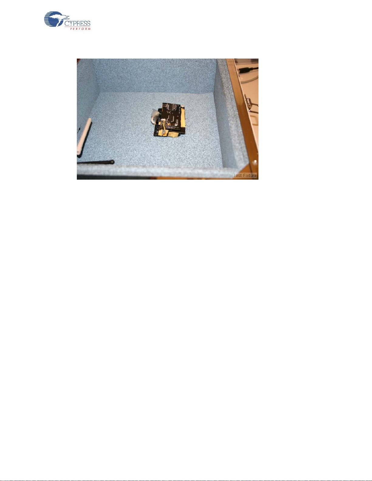
place it in the shielded container. The DUT should respond to the standard test executed by the test
fixture. Note that the foam in some shielded test boxes is conductive. The bare DUT board (if testing
a bare PCB) should be placed in a fixture, not directly on the foam of th e box. This also he lps e nsure
that the DUT to antenna alignment is the same from test to test, which can make a large difference in
signal strength at the DUT. See Figure 2-3.
8 CY3631 WirelessUSB™ Manufacturing Test Kit User Guide, Doc. # 001-66724 Rev. *B
Page 9
Kit Operation
Figure 2-3. DUT Fixture
Press the START button on the test fixture. The BUSY light comes on for a short time. If the test is
successful, then the PASS light comes on when the test is completed. If the test exceeds the error
threshold settings, the test fixture indicates test failure by lighting the FAIL light.
2.3 Calibration
The test station is calibrated by usin g one or more kn own good refere nce devices to dete rmine the
maximum attenuation that the system can have installed before the radio loses good contact. This
must be done periodically to compensate for environmental effects, and at least once any time the
DUT design is changed or the test station is switched to testing a different device model.
Antenna distance and orientation, to each other and to the walls of the test chamber, are important
for signal attenuation. Therefore it is vital that the calibration and test procedure be run with the
antenna and DUT installed in the same location and orientation every time. It is recommended that
you use a test fixture, or some other means, to ensure proper placement of the DUT each time. If
alignment guides are added to the chamber, they should be kept to a very low profile and they
should be constructed out of a non reflecting material. One option is to cut a shallow impression in
the foam at the bottom of the chamber that holds the DUT in the proper alignment.
Note that the foam in some test chambers is conductive. While testing bare boards, be sure to use a
fixture or some other means to insulate the board from th e foam. A test fixture tha t holds th e board in
exactly the same place every time is strongly recommended.
Any wires or battery packs that are placed in the chamber to power the DUT also need to be in the
same location every time, as these can reflect the RF energy and change the overall attenuation of
the signal. Batteries should ideally be used and placed in their final location, as they will be in the finished product. The battery position can affect the test results. If the battery is not in the finished product's position, the test works fine, as long as the batteries are in the same position each time the test
is run.
CY3631 WirelessUSB™ Manufacturing Test Kit User Guide, Doc. # 001-66724 Rev. *B 9
Page 10

Kit Operation
The initial calibration is easily done using a variable attenuator rather than the fixed attenuators
provided in the kit. This is shown in Figure 2-4. If the variable attenuator used does not have
sufficient range, it may be necessary to install both the variable and some fixed attenuation. The
amount of fixed attenuation must be determined by trial and error.
Figure 2-4. Calibration Setup
The calibration begins by testing a known good DUT sample (golden DUT) with a ‘best guess’
attenuation value. Based on our experience, this is ty pically in the 40 dB rang e. The test s tarts, and
should pass at this initial setting. If it does not, the attenuation may need to be reduced by 10 dB. If a
second test with this reduced attenuation still does not pass, check all the connections to be sure
that everything is connected correctly. If this still does not fix the problem, attach the antenna directly
to the SMA on the MTK test fixture and test the golden DUT in free air (no chamber). If this still does
not pass, make sure that the test fixture has power, press the reset button (the self-test should pass
and the green LED remain lit), and make sure that the golden DUT has good batteries installed and
is in MTK test mode.
After a base line is established by passing the test, the attenuation is increased and the test
repeated. Doing this several times, increasing the attenuation each time, eventually reaches the
level where the golden DUT fails the test repeatedly at a given attenuation. There may be an
intermediate attenuation value at which the test passes only sometimes. Use your discretion on how
to determine the limit value. One option is to consider the test passing (for calibration only) if it
passes three or more of five tests. As long as the method used is consistent, the results will be
consistent.
It may be helpful to repeat the test with additional known good units recording the attenuation limit
for each, especially for a new product. Eventually, a “worst of the best” unit can be retained for future
calibration use. This is a unit that, while good and passing all the requirements, exhibits the lowest
attenuation limit ever seen in a good unit.
Now that a limit has been found, the fixed attenuation should be installed in the cable. The total
attenuation should be selected such that it is lower than the limit value found using the golden units
by some guard band (–3 dB, for example.) The type of defect results in far greater than 3 dB of
reduction in either transmit power or receive sensitivity.
Finally, the golden DUT should be tested once more with the fixed attenuation installed to ensure
that the setup is still working. The test should pass repeatedly. If it does not, check the attenuation
value and all connections again.
10 CY3631 WirelessUSB™ Manufacturing Test Kit User Guide, Doc. # 001-66724 Rev. *B
Page 11
3. Hardware
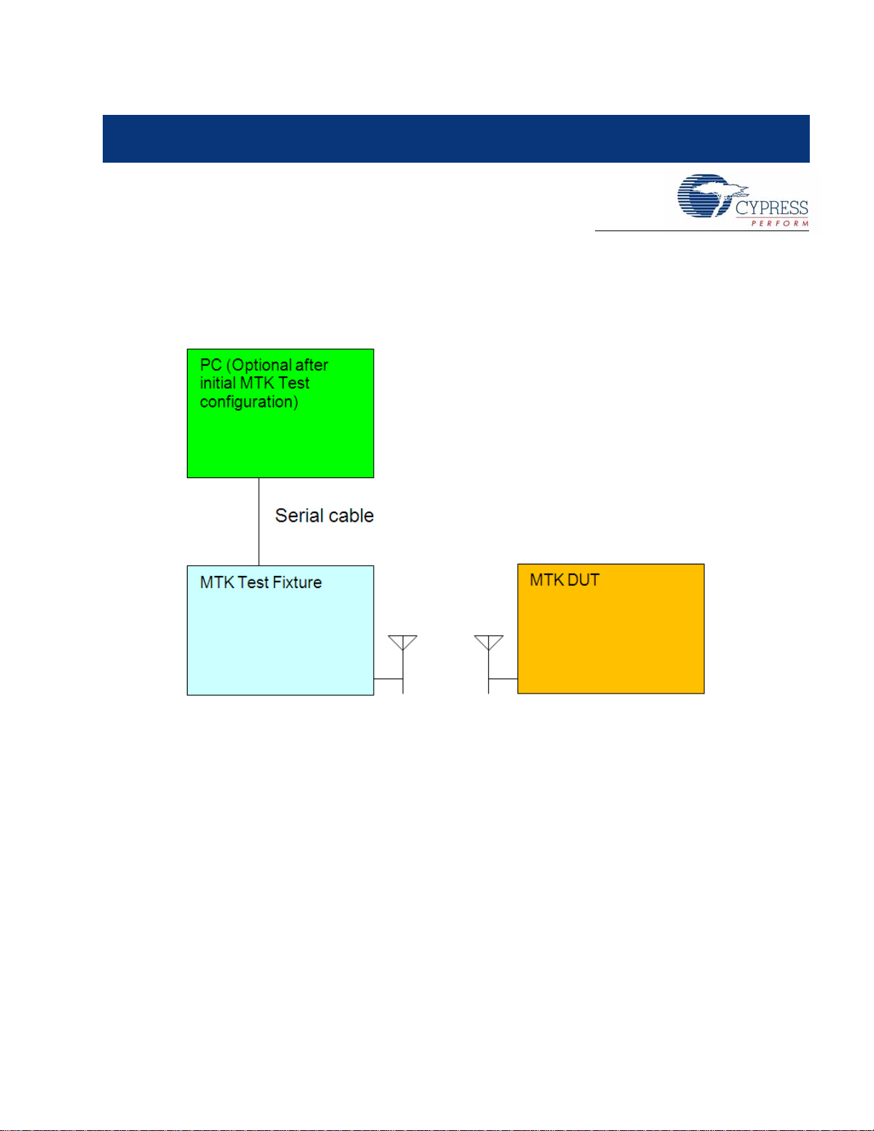
The manufacturing testing syste m involves three major comp onents: MTK test fixture, MTK devic e
under test (DUT), and an optional PC to monitor and control the MTK test fixture.
Figure 3-1. System Diagram
3.1 Theory of Operation
By default the MTK test fixture executes a set of standard tests when you push the START button. It
sends predetermined test packets to the MTK DUT and expects the MTK DUT to reply to the same
packet with the RX status. LEDs on the test fixture indicate if the test succeeds or fails.
To change the parameters for standard tests, such as channel number, number of packets, packet
length, and so on, it can be done throug h a control PC. The MTK test fixture provides a RS232 port
and its firmware runs command line protocol. You can use any serial communication application
such as a HyperTerminal to send comm ands to and rece ive status from test fixtur e. See Command
Line Interface on page 17 for details.
3.2 Schematic
The MTK test fixture’s main board schematic is included in the kit under <CD/DVD>/Hardware.
CY3631 WirelessUSB™ Manufacturing Test Kit User Guide, Doc. # 001-66724 Rev. *B 11
Page 12

Hardware
12 CY3631 WirelessUSB™ Manufacturing Test Kit User Guide, Doc. # 001-66724 Rev. *B
Page 13

4. Firmware
4.1 Overview
The MTK test firmware is divided into tw o parts: the Test Fixture firmware and the DUT Test Code.
The DUT test code is a small bit of additional code that resides in the DUT memory and can be
accessed only by placing the DUT into a special test mode (see section 4.2 DUT Test Code for more
details). In test mode, the DUT in the test chamber exchanges packets with the test fixture. The data
packet from the test fixture to the DUT is checked for errors by the DUT and the error count
recorded. The DUT then sends a data packet back to the test fixture that includes the error count
information. The test fixture uses this information, as well as information it collects ab out errors in the
received data packet from the DUT, to determine if the test passes or fails.
4.2 DUT Test Code
All packets received by the DUT are ‘echoed’ with the addition of a byte that contains the count of
invalid bits for the received packet. Extra bytes in packets that are larger than what the DUT can
support are ignored. Received packets of the correct length are then parsed for possible RF
command packets. The RF command packets exchanged between the MTK test fixture and the
MTK DUT contain two or more bytes. Th e first byte contains the command type and the remaining
bytes contain the parameter value. All commands are executed after the received packets are
‘echoed’.
The DUT manufacturing test code adds approximately 500–800 bytes depending on the device and
firmware version. The CY4672 PRoC LP RDK Bridge enters the Manufacturing Test Mode when the
Bind button on the Bridge is pressed during power on. The CY46 72 RDK mouse and keyboar d use a
compile time define to enter the test mode by detecting a specific grounded pin or a special key
sequence during power-up. The following sections provide the details (the process of testing the
CY4636 WirelessUSB LP RDK is also the same).
4.2.1 CY4672 PRoC LP RDK Bridge
The manufacturing test module may be conditionally compiled to provide manufacturing test
support. The module configures the radio for reception and then enters a loop waiting for command
packets to be sent from the tester. The test echoes all echo command packets appended with the
number of invalid bits received and all other 'valid' command packets (no invalid bits). The
manufacturing test code can only be exited by cycling power.
You can enter the manufacturing test mode on the PRoC LP RDK Bridge using the following
methods depending on the compile time configuration:
1. Press the Bind button during dongle insertion into the USB Host.
2. Force a SE1 condition (D+ and D– are both high) on the USB bus and, at the same time, apply
power to the bridge.
3. Ground the P0.7 pin during dongle insertion into the USB Host.
CY3631 WirelessUSB™ Manufacturing Test Kit User Guide, Doc. # 001-66724 Rev. *B 13
Page 14

Firmware
4.2.2 CY4672 PRoC LP RDK Mouse
The manufacturing test module may be optionally compiled, at the expense of code space, by
defining the macro MFG_TEST_CODE. In addition, a more complete version may be compiled by
defining MFG_TX_MODES. The TX modes include the code to perform a carrier test and a random
data test. Entry into this mode on the mouse is performed by placing a shorting block over pin s 4 and
5 of the ISSP programming header and then inserting the batteries. To exit the test mode, remove
the batteries and the shorting block.
4.2.3 CY4672 PRoC LP RDK Keyboard
The RDK provides a compile time option to add a manufacturing test mode to the keyboard. If
MFG_TEST_CODE is defined and ENTER_BY_PIN is not defined, you can enter the manufacturing
test mode by holding down the system sleep key and the Bind button, while inserting the batteries
into the keyboard.
If MFG_TEST_CODE and ENTER_BY_PIN are both defined, you can enter the manufacturing test
mode by connecting pins 4 and 5 on the ISSP header with a shunt and then inserting the batteries
into the keyboard. The only way to exit this mode is to cycle power.
4.3 Test Fixture Firmware
The test fixture firmware controls the standard test that is executed when the START button is
®
pressed. It also enables communication over the serial port. The source code for PSoC
test fixture is included in the kit CD-ROM. You may customize the test firmware as desired. PSo C
can be reprogrammed using the ISSP header on the board. Figure 4-1 shows the location of the
header.
Figure 4-1. ISSP Header Location
in the MTK
14 CY3631 WirelessUSB™ Manufacturing Test Kit User Guide, Doc. # 001-66724 Rev. *B
Page 15

4.4 RF Protocol
Command packets received by the DUT are “echoed” with the addition of an added byte that
contains the count of invalid bits for the received packet. Extra bytes in packets that are larger than
what the DUT can support are ignored. Commands other than “Echo Packet” are only “echoed” and
executed if the number of invalid bits are zero.
The RF command packets exchanged between the MTK test fixture and the MTK DUT contain two
bytes. The first byte contains the command type and the subsequent byte(s) contain the parameter
values as shown in Table 4-1.
Table 4-1. RF Commands
Description Command Parameter
Echo packet 0x00 N/A
Set new configuration 0x61
Firmware
Channel (0–77)
PN code index (0–7)
PA (0–7)
Correlator Threshold (0–16)
Transmit carrier 0x66
Transmit random pattern 0xA3
Time in seconds (0–255)
Note: A zero runs the test continuously until a reset.
Time in seconds (0–255)
Note: A zero runs the test continuously until a reset.
Note The “Transmit carrier” and “Transmit random pattern” test modes can be conditionally com piled
with the definition “MFG_TX_MODES”.
CY3631 WirelessUSB™ Manufacturing Test Kit User Guide, Doc. # 001-66724 Rev. *B 15
Page 16

Firmware
16 CY3631 WirelessUSB™ Manufacturing Test Kit User Guide, Doc. # 001-66724 Rev. *B
Page 17
5. Command Line Interface
5.1 Serial Command Line Interface
The MTK test fixture implements a text-based protocol over an RS232 serial port to provide both a
configurable standard test and script-based testing.
All commands listed under the standard test set a configuration value that is stored in nonvolatile
storage. All remaining serial commands only affect the current setting and are not stored (reset
across power cycles). Table 5-1 describes the serial port protocol in the PC to test fixture direction.
Table 5-1. Serial Command Protocol
Command Command Description
ST Start standard test
PN <PN code> Configure pin code index (0–7)
TT <tx error threshold> Configure TX error threshold (0–65535) units of bit errors
RT <rx error threshold> Configure RX error threshold (0–65535) units of bit errors
C1 <channel> Configure channel (0–77)
C2 <channel> Configure second channel (0–77)
C3 <channel> Configure third channel (0–77)
CB <# of bytes> Configure number of bytes/packet payload (0–15)
TC <time> Transmit carrier (0–255)
TR <time> Transmit random (0–255)
SC <channel> <PN code>
<power level> <correlator
threshold>
PD <packet data>
CA <crystal adjust> Set crystal frequency adjust value (0–63)
RE Restore NVRAM defaults
CS Show current configuration
HE Show help menu
Set communication (0–77) (0–7) (0–7) (0–16)
Set packet data (ASCII representation of hexadecimal numbers without any
prefix, that is, 5A 34 CB)
CY3631 WirelessUSB™ Manufacturing Test Kit User Guide, Doc. # 001-66724 Rev. *B 17
Page 18
Command Line Interface
Every serial command issued by the PC is returned with a response afte r the command is comp lete.
The valid responses are shown in Table 5-2.
Table 5-2. Serial Response Protocol
OK Command complete
CE Command error
TE <transmit error count> TX error count (units of bit errors)
RE <receive error count> RX error count (units of bit errors)
All serial commands must end in either a carriage return or carriage return and linefeed. All
responses end with a carriage return and linefee d.
The serial port settings for the MTK test fixture are shown in Table 5-3. Neither software nor
hardware handshake is supported.
Table 5-3. Serial Port Parameter Settings
Report Report Description
Serial Port Parameter Setting
Baud rate 9600
Parity None
Number of data bits 8
Number of stop bits 1
18 CY3631 WirelessUSB™ Manufacturing Test Kit User Guide, Doc. # 001-66724 Rev. *B
Page 19

1. Appendix
1.1 Appendix - A
1.1.1 Using the Command Line Interface
The default serial port settings for the test fixture are 9600, N, 8, 1, NONE, with local echo turned on
in the terminal emulator of choice. Wh en power is applied to the test fixture, the following welcome
banner comes up in the terminal window.
******************************************************************************
WirelessUSB Tester - v1.0
For help, type: he
******************************************************************************
MTK>
If this banner is not displayed, then recheck the serial port connection and settings.
All serial port commands are case insensitive. While the help menu displays commands in upper
case, they may be entered in lower case. The PD command requires parameters to be entered in
hexadecimal format without any prefix or postfix ch aracters ( see the help men u for an exampl e.) The
letters in the hexadecimal numbers may be lowercase as well.
A listing of all the supported commands with parameter limits is displayed by typing the command
HE as shown in the welcome banner. Following is an output example of the help menu.
MTK> he
TESTER HELP MENU
******************************************************************************
All commands and parameters are case insensitive. The following commands are executed immediately:
Show This Help Menu ........................... HE
Show Current Tester Settings .................. CS
Execute Standard Test ......................... ST
Set Channel, PN Code, Power, Correlator ....... SC <0-77> <0-7> <0-7>
<0-16>
Transmit Carrier for N seconds, 0 = infinite .. TC <0-255>
Transmit Random for N seconds, 0 = infinite ... TR <0-255>
Send Data to DUT, e.g. PD 5A 00 0A FF 34 ...... PD <B1 B2 ... B15>
Tester Crystal Adjust (stored in EEPROM) ...... CA <0-63>
Crystal Clock Output ON=1/OFF=0 ............... XO <0-1>
Restore Default Settings to EEPROM ............ RE
CY3631 WirelessUSB™ Manufacturing Test Kit User Guide, Doc. # 001-66724 Rev. *B 19
Page 20

The following commands save values to EEPROM for standard test configuration:
Configure Correlator Threshold ................ CO <0-16>
Configure Power Level ......................... CL <0-7>
Configure PN Code ............................. PN <0-7>
Configure First Channel, 255 to disable ....... C1 <0-77, 255>
Configure Second Channel, 255 to disable ...... C2 <0-77, 255>
Configure Third Channel, 255 to disable ....... C3 <0-77, 255>
Configure Tx Error Threshold .................. TT <0-65535>
Configure Rx Error Threshold .................. RT <0-65535>
Configure Packet Payload Length ............... CB <0-15>
Configure Number of Packets Sent on Channel ... CP <0-255>
All commands return one of the following:
OK ................. Command Success
CE ................. Command Error
Commands PD and ST also return:
TE <number> ........ DUT Receive Error Rate
RE <number> ........ Tester Receive Error Rate
******************************************************************************
OK
MTK>
All commands return either OK (successful command completion) or CE (command error.) A successful command completion in the case where DUT interaction is involved does not necessarily
mean that the DUT successfully completed the request.
The PD command and the Standard Test command ST both report additional information of bit error
rates. The TE result is the number of bit errors counted by the DUT and is computed on the test
fixture by using the contents of the returned packet from the DUT. If a response to a data packet is
not received by the test fixture, then a 100% bit error rate is assumed on the sent packet. The RE
result is computed using the received packet from the DUT.
A portion of the commands are used to configure the Standard Test that is executed by pressing the
START button on the test fixture. These values are saved in nonvolatile storage and remembered
across power cycles. The saved values only take affect when the Standard Test is executed.
The current configuration of the test fixture can be reported by typing the command CS at the
command prompt. Following is an example of the output from this command.
MTK> cs
TESTER CONFIGURATION
******************************************************************************
Radio Configuration:
Channel .................. 2
PN Code .................. 1
Power Level .............. 7
Correlator threshold ..... 2
Crystal adjust ........... 3
Crystal clock output ..... OFF
Standard Test Configuration:
Channel 1 ................ 1
Channel 2 ................ 255
Channel 3 ................ 255
PN Code .................. 1
Power Level .............. 7
Correlator threshold ..... 2
20 CY3631 WirelessUSB™ Manufacturing Test Kit User Guide, Doc. # 001-66724 Rev. *B
Page 21

Tx error threshold ....... 1000
Rx error threshold ....... 1000
Packet payload length .... 5
Packets per channel ...... 128
******************************************************************************
WUSB LS Radio Registers
Output format in hex: addr:val
00:07 01:04 02:4a 03:00 04:06 05:01 06:0b 07:03
08:00 09:00 0a:00 0b:00 0c:00 0d:01 0e:00 0f:00
10:ff 11:dc 12:c0 13:6b 14:b8 15:2b 16:09 17:bb
18:b2 19:02 1a:1e 1b:10 1c:00 1d:01 1e:00 1f:00
20:64 21:04 22:00 23:07 24:42 25:00 26:0f 27:00
28:00 29:00 2a:00 2b:10 2c:fa 2d:f0 2e:80 2f:00
30:00 31:00 32:41 33:41 34:f7 35:00 36:00 37:63
38:64 39:00 3a:00 3b:00 3c:d3 3d:8a 3e:d5 3f:3e
******************************************************************************
OK
MTK>
The standard test can be executed from the PC by typing the ST command at the command prompt
in the terminal window. The first channel is set to 255 and all following channels are not tested. The
results are displayed in the terminal similar to the following.
MTK> st
TE 864
RE 1008
OK
MTK>
The error results in the previous paragraph are typical of a non responding DUT.
Note that when pressing the START button on the test fixture that th e test result s are displayed in the
terminal window without the command response and command prompt as follows.
TE 864
RE 1008
The commands not related to the Standard Test configuration are executed immediately from the
command prompt. These are used for interactive testing/debug or with a script for extended
automated testing.
CY3631 WirelessUSB™ Manufacturing Test Kit User Guide, Doc. # 001-66724 Rev. *B 21
Page 22

1.2 Appendix - B
1.2.1 Test Chambers
An anechoic RF test chamber, sized appropria tely for the DUT with SMA pass through connectors is
required.
There are several important factors to consider when buying a chamber, such as the attenuation of
RF energy that comes into the box from outside, the attenuation of RF energy that is reflected from
the inside of the box, and the connectors for passing signals through the walls.
The requirements are as follows:
■ Attenuation of incoming RF energy: 30 dB at 2.4 GHz
■ Attenuation of reflected RF energy: 15 dB at 2.4 GHz ( 7.5 dB each direction)
■ Connectors: One (1) SMA minimum
Many vendors sell test chambers that work. Following are some examples of units used before:
■ Mironix model ME8662E
■ Ramsey Electronics model STE2200 with optional CONN157. (A small box nicely sized for a
mouse or dongle, or small bare boards.)
■ Ramsey Electronics model STE3300 with optional CONN157.
■ Ramsey Electronics model STE4400 with optional CONN157. (Large enough for a full size
keyboard in plastic.)
22 CY3631 WirelessUSB™ Manufacturing Test Kit User Guide, Doc. # 001-66724 Rev. *B
Page 23

Mouser Electronics
Authorized Distributor
Click to View Pricing, Inventory, Delivery & Lifecycle Information:
Cypress Semiconductor:
CY3631
 Loading...