

Page 1

CPLUS-VPE2DD
4K UHD+ HDMI Dolby Digital & DTS
Stereo Decoder
Operation Manual
Operation Manual
Page 2

Page 3

DISCLAIMERS
The information in this manual has been carefully checked and
is believed to be accurate. Cypress Technology assumes no
responsibility for any infringements of patents or other rights of third
parties which may result from its use.
Cypress Technology assumes no responsibility for any inaccuracies
that may be contained in this document. Cypress also makes no
commitment to update or to keep current the information contained
in this document.
Cypress Technology reserves the right to make improvements to this
document and/or product at any time and without notice.
COPYRIGHT NOTICE
No part of this document may be reproduced, transmitted,
transcribed, stored in a retrieval system, or any of its part translated
into any language or computer le, in any form or by any means—
electronic, mechanical, magnetic, optical, chemical, manual, or
otherwise—without express written permission and consent from
Cypress Technology.
© Copyright 2018 by Cypress Technology.
All Rights Reserved.
TRADEMARK ACKNOWLEDGMENTS
All products or service names mentioned in this document may be
trademarks of the companies with which they are associated.
Manufactured under license from Dolby
Laboratories. Dolby and the double-D symbol are
trademarks of Dolby Laboratories.
Manufactured under license under U.S. Patent
Nos: 5,956,674; 5,974,380; 6,487,535 & other U.S.
and worldwide patents issued & pending. DTS,
the Symbol, & DTS and the Symbol together are
registered trademarks & DTS 2.0+Digital Out is a
trademark of DTS, Inc. Product includes software.
© DTS, Inc. All Rights Reserved.
Page 4

SAFETY PRECAUTIONS
Please read all instructions before attempting to unpack, install or
operate this equipment and before connecting the power supply.
Please keep the following in mind as you unpack and install this
equipment:
• Always follow basic safety precautions to reduce the risk of re,
electrical shock and injury to persons.
• To prevent re or shock hazard, do not expose the unit to rain,
moisture or install this product near water.
• Never spill liquid of any kind on or into this product.
• Never push an object of any kind into this product through any
openings or empty slots in the unit, as you may damage parts
inside the unit.
• Do not attach the power supply cabling to building surfaces.
• Use only the supplied power supply unit (PSU). Do not use the PSU
if it is damaged.
• Do not allow anything to rest on the power cabling or allow any
weight to be placed upon it or any person walk on it.
• To protect the unit from overheating, do not block any vents or
openings in the unit housing that provide ventilation and allow for
sufcient space for air to circulate around the unit.
REVISION HISTORY
VERSION NO. DATE SUMMARY OF CHANGE
RDV1 17/07/15 Preliminary release
VS1 12/02/18 Final technical review
Page 5

CONTENTS
1. Introduction ......................................................1
2. Applications .....................................................1
3. Package Contents ..........................................1
4. System Requirements ......................................1
5. Features ............................................................2
6. Operation Controls and Functions .................3
6.1 Front Panel ................................................. 3
6.2 Rear Panel .................................................. 4
6.3 Virtual COM Port Control ......................... 5
6.4 EDID Commander ..................................... 7
6.4.1 EDID Controller Tab .......................... 7
6.4.2 EDID Creator Tab ............................. 8
6.4.3 System Tab ........................................ 9
7. Connection Diagram ....................................10
8. Specications ................................................11
8.1 Technical Specications ........................ 11
8.2 Video Specications ............................... 12
8.3 Audio Specications ............................... 13
9. Acronyms .......................................................14
Page 6

1. INTRODUCTION
This HDMI Dolby Digital & DTS Stereo Decoder supports the transmission
of high bandwidth (18Gbps) video and allows the associated audio
signal to be simultaneously extracted and split to both digital and
analog audio outputs, providing high quality audio and video
performance.
This unit can decode standard Dolby Digital & DTS formats up to 5.1
and output the audio as stereo (LPCM 2.0) over HDMI, S/PDIF (optical
and coaxial) and analog RCA connections. It can also support the
passthrough of Bitstream, HD Bitstream, or LPCM 7.1 with audio
sampling rates up to 192kHz if needed. If the connected display
supports ARC (Audio Return Channel), and has it enabled, then this
unit can extract the ARC audio and output it via all available audio
outputs.
Both the input and output HDMI ports support 4K UHD resolutions up
to 4K@60Hz (4:4:4, 8-bit). Built-in EDID management support allows
the user to select from multiple EDIDs and, with the use of optional PC
software, to upload, download, or edit EDID les.
2. APPLICATIONS
• Audio extraction for use with non-HDMI AV receivers or powered
speaker systems
• AV system integration and home theater installation
• Supporting HDMI sources on DVI displays with analog or external
speaker systems
• HDMI/DVI EDID management
3. PACKAGE CONTENTS
• 1×HDMI Dolby Digital & DTS Stereo Decoder
• 1×5V/2.6A DC Power Adapter
• 1×Operation Manual
4. SYSTEM REQUIREMENTS
• HDMI source equipment such as a media player, video game
console or set-top box.
1
Page 7

• HDMI receiving equipment such as an HDTV, monitor or audio
amplier.
• Audio receiving equipment such as an audio amplier or powered
speakers.
• The use of “Premium High Speed HDMI” cables is highly
recommended.
5. FEATURES
• HDMI input and output with 18Gbps (600MHz) 4K UHD support
• DVI 1.0 compatible with the use of an HDMI-DVI adaptor
• HDCP 1.4 and 2.2 compliant
• Supports HD resolutions up to 3840×2160@60Hz (4:4:4, 8-bit) &
4096×2160@60Hz (4:4:4, 8-bit)
• Supports 48-bit Deep Color up to 1080p@60Hz
• Supports passthrough of LPCM 7.1, Bitstream and HD Bitstream
audio formats over HDMI
• Embedded Dolby Digital Decoder technology
• Embedded DTS 2.0+Digital Out Decoder technology
• Integrated digital interpolation lter and Digital-to-Analog Converter
(DAC)
• Supports LPCM sampling rates up to 96kHz
• Supports Dolby Digital sampling rates up to 48kHz
• Supports DTS sampling rates up to 96kHz
• Simultaneous audio output via HDMI, analog stereo, Coaxial and
Optical
• Supports coaxial and optical audio sampling rates up to 96kHz
• Supports extracting the HDMI audio signal from an HDTV’s ARC
feature
• Provides EDID management with EDID bypass and 1 user modiable
EDID
• PC based EDID management tool support
• Supports RS-232 style control via a Virtual COM port over USB
2
Page 8

6. OPERATION CONTROLS AND FUNCTIONS
1 2 3 4 5
6.1 Front Panel
POWER PCM
4K UHD+ Dolby Digital & DTS Stereo Decoder
POWER: This LED will illuminate to indicate the unit is on and
1
D
ARC
receiving power.
PCM: This LED will illuminate when LPCM audio is detected on the
2
HDMI input. If the ARC function is active, this LED will illuminate
when LPCM is detected from the ARC source.
DTS: This LED will illuminate when DTS 2.0+Digital audio is detected
3
on the HDMI input. If the ARC function is active, this LED will
illuminate when DTS 2.0+Digital audio is detected from the ARC
source.
DOLBY DIGITAL: This LED will illuminate when Dolby Digital audio is
4
detected on the HDMI input. If the ARC function is active, this LED
will illuminate when Dolby Digital audio is detected from the ARC
source.
ARC: Pressing the this button will enable/disable the unit’s ARC
5
(Audio Return Channel) functionality. When the ARC function is
enabled, the LED will illuminate and ARC audio sent back from
the connected display will be output over all local audio outputs.
When the ARC function is not enabled the LED will remain off.
Note: Please ensure that the connected display supports ARC and
that the display’s ARC function is enabled before activating the
ARC functionality of this unit. Failure to meet these requirements
will result in no audio output.
3
Page 9

6.2 Rear Panel
1 2 3 4 5 6 7 8
HDMI OUTHDMI IN
HDMI IN: Connect to HDMI source equipment such as a media
1
AUDIO OUT
LRCOAX
OPTICAL
SPDIF EDID SERVICE
HDMI
AUDIO
BYPASS/
BYPASS/
2CH
2CH
STD/
TV
DC 5V
player, game console or set-top box.
HDMI OUT: Connect to an HDMI TV, monitor or amplier for digital
2
video and audio output.
L/R OUT: Connect to powered speakers or an amplier for stereo
3
analog audio output.
COAX OUT: Connect to powered speakers or an amplier for
digital audio output using an appropriate coaxial cable.
OPTICAL OUT: Connect to powered speakers or an amplier for
digital audio output using an appropriate optical cable.
HDMI AUDIO BYPASS/2CH: This switch controls the audio output
4
format for the HDMI port. Moving the switch to the left sets it to
“BYPASS” which allows audio to pass unchanged from the HDMI
input port. Moving the switch to the right sets it to “2CH” which
enables decoding Dolby Digital and DTS audio from the HDMI
input and down-mixing it to LPCM 2.0.
S/PDIF BYPASS/2CH: This switch controls the audio output format
5
for the S/PDIF audio output ports (Optical and Coaxial). Moving
the switch to the left sets it to “BYPASS” which allows audio to pass
unchanged from the HDMI input port. Moving the switch to the
right sets it to “2CH” which enables decoding Dolby Digital and
DTS audio from the HDMI input and down-mixing it to LPCM 2.0.
EDID STD/TV: This switch controls which EDID is sent to the
6
connected HDMI input device. Moving the switch to the left sets
it to “STD” mode which will use the internal (user) EDID. Moving
the switch to the right sets it to “TV” mode which will pass the EDID
from the connected display device to the HDMI input device.
Note: By default the “STD” EDID contains video resolution support
up to 1080p@60Hz and audio support including LPCM 2.0 up to
4
Page 10

96kHz, Dolby Digital (5.1 channel) and DTS (5.1 channel).
SERVICE: This slot is for EDID management, control and rmware
7
update use. Connect directly to your PC/laptop using a standard
Mini-USB cable to connect using the PC software or to send
commands (via virtual COM port).
DC 5V: Plug the 5V DC power adapter into the unit and connect it
8
to an AC wall outlet for power.
6.3 Virtual COM Port Control
COM PORT SETTINGS
Baud rate 115200
Data bits 8
Parity None
Stop bits 1
Flow control None
COMMAND DESCRIPTION & PARAMETERS
? Show the full command list.
HELP Show the full command list.
SOURCEDET Show the current input source detection
state.
SINKINFO Show information about the currently
connected display.
HDCPIN N1 Set the HDCP handling mode for the HDMI
input.
Available values for N1:
1 [Follow Input]
2 [Follow Output]
3 [Apple Mode]
HDCPIN ? Show the current HDCP handling mode.
5
Page 11

COMMAND DESCRIPTION & PARAMETERS
ECHO N1 Set the console text echo mode behavior.
Available values for N1:
0 [Text echoing is off]
1 [Text echoing is on]
ECHO ? Show the current text echoing mode.
FADEFAULT Reset the unit to the factory defaults.
VER Show the unit’s current rmware version.
REBOOT Reboot the unit.
Note: Commands will not be executed unless followed by a carriage
return. Commands are not case-sensitive.
6
Page 12
6.4 EDID Commander
(1) This unit uses an EDID Management application which allows the
user to copy the EDID from an attached display, edit an existing
EDID le stored on the PC or create a basic EDID from scratch. The
EDID can then be uploaded to the unit for use.
(2) Please obtain the EDID Management software from your
authorized dealer and save it in a directory where you can easily
nd it.
(3) Before connecting the unit to your PC, please install the
appropriate Virtual COM Port Driver depending on your Windows
version. Next, install the EDID Management software.
(4) After the installation has successfully completed, an icon for it will
appear on the windows desktop. Launch the software by doubleclicking on the icon and the EDID Management device detection
window will open up on your screen.
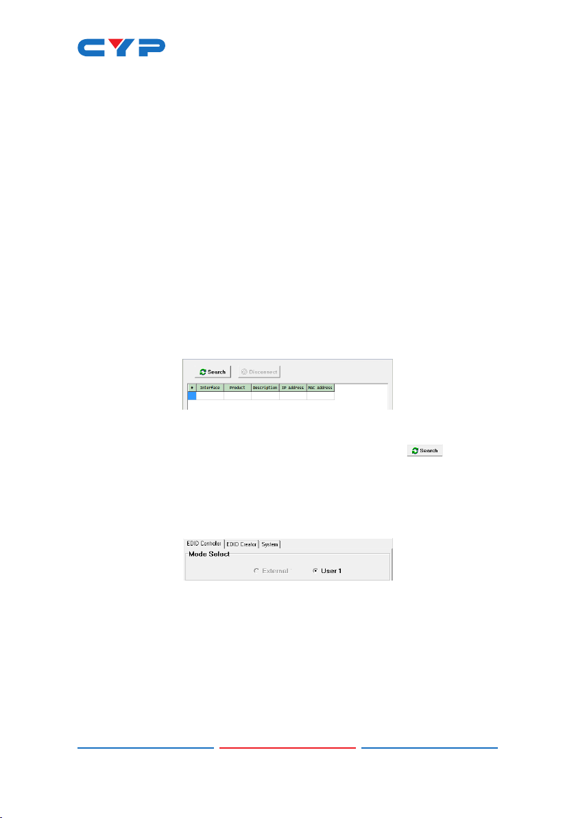
(5) After launching the software, power the unit on and then connect
it to the PC/laptop using a USB cable. Click on the “ Search”
button and any detected units will be displayed in the list. Clicking
on a detected unit will open the EDID Commander window.
6.4.1 EDID Controller Tab
• Mode Select: The currently selected EDID is displayed here.
- The “External” EDID corresponds to the “TV” setting on the back of
the unit. The “User 1” EDID corresponds to the “STD” setting on the
back of the unit. The User 1 EDID is user-replaceable.
- To return the User 1 EDID to its original values, please perform a
factory reset on the unit.
7
Page 13
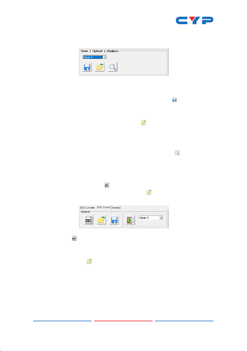
• Save/Upload/Analysis: EDIDs may be saved to a PC, uploaded from
a PC or analyzed.
- Save: Any EDID from the unit or the connected HDMI display can
be saved to your PC as a *.bin le by selecting the EDID source
from the drop down menu and then clicking the “ Save” icon.
- Upload: Previously saved EDID les (*.bin format) can be re-
uploaded into the unit by selecting the User EDID to replace from
the dropdown and then clicking the “ Upload” icon. Before
accepting the upload, the software will check and verify that the
EDID’s header and checksum values are acceptable.
- Analysis: To analyze any EDID stored within the unit, select the
EDID to view from the dropdown and click on the “ Analysis”
icon.
6.4.2 EDID Creator Tab
• Select: Click on the EDID Creator tab to begin designing a new EDID
from scratch (select the “ New” icon), to modify an existing EDID
stored on the PC as a .bin le (select the “ Load” icon) or to edit
an EDID copied from the unit via the EDID Analyzer’s edit option.
- Selecting “ New” will automatically populate the various EDID
elds with basic information that can be easily edited to match
the user’s preferences.
- Clicking on the “ Load” icon will open a le load window and
after the *.bin le has been selected and loaded the EDID elds
will be populated with the information from that le. The same will
happen when the EDID is copied from the EDID Analyzer window.
8
Page 14
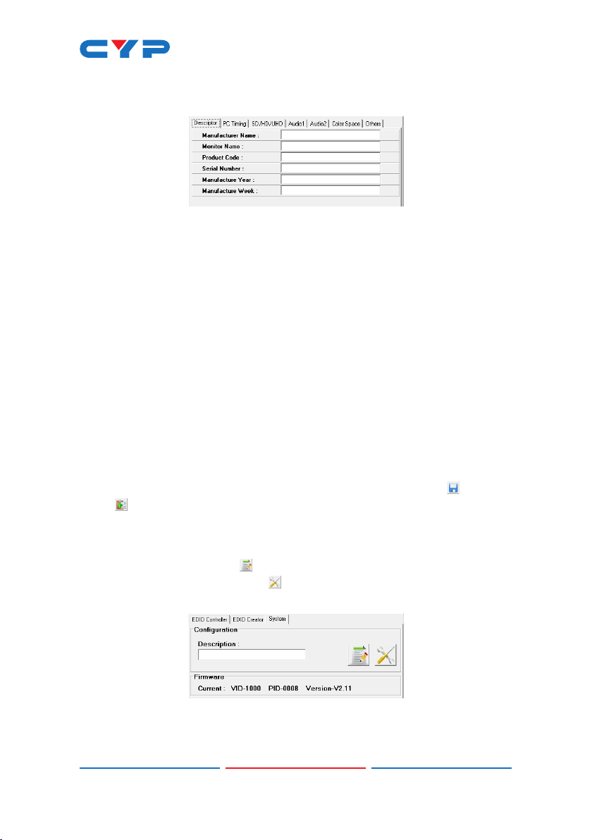
• Edit: The following tabs provide access to a wide range of EDID
information which can be edited:
- Descriptor: This tab allows for the editing of various description
and information elds within the EDID le such as Manufacturer
Name, Monitor Name, etc.
- PC Timing & SD/HD/UHD: These tabs allow for the selection of the
resolutions and refresh rates that the EDID will report as supported.
- Audio1 & Audio2: These tabs allow for the selection of which
audio formats, audio frequencies, channels and speaker locations
are supported.
- Color Space: This tab allows for the selection of which color
formats and bit depths are supported, including BT.2020 and HDR
support options.
- Others: This tab contains options for supporting 3D and dening
the CEC Address.
Once the user is nished editing or creating an EDID it can be saved to
a *.bin le locally or uploaded directly to the unit using the “ Save”
and “ Upload” icons respectively.
6.4.3 System Tab
• Conguration & Firmware: Select the System tab to edit the unit’s
description (select the “ Rename” icon), to reset the unit to
factory defaults (select the “ Reset” icon) and to view the unit’s
current hardware and rmware version information.
9
Page 15

7. CONNECTION DIAGRAM
4K Media Player
HDMI Input
HDMI OUTHDMI IN
ARC Input
AUDIO OUT
LRCOAX
Virtual COM Port
USB
SPDIF EDID SERVICE
HDMI
AUDIO
DC 5V
BYPASS/
STD/
BYPASS/
OPTICAL
2CH
TV
2CH
Enabled PC
Power Supply
HDMI Output
(Downmixed or
Bypassed)
S/PDIF Outputs
(Downmixed or
Bypassed)
Stereo Output
(Downmixed)
UHDTV Powered Speakers AV Receiver
10
Page 16

8. SPECIFICATIONS
8.1 Technical Specications
HDMI Bandwidth 600MHz/18Gbps
Input Port 1×HDMI
Output Ports 1×HDMI
1×Optical (S/PDIF)
1×Coaxial (S/PDIF)
2×RCA (Stereo)
Control Interface 1×USB Mini-B
HDMI Cable Length 10m (1080p@60Hz, 12-bit)
3m (4K@60Hz, 4:4:4, 8-bit)
Baud Rate Up to 115200bps
Power Supply 5V/2.6A DC
(US/EU standards, CE/FCC/UL certied)
ESD Protection Human Body Model:
±8kV (Air Discharge)
±4kV (Contact Discharge)
Dimensions 180mm×25mm×104mm (W×H×D)
[Case Only]
180mm×25mm×111.75mm (W×H×D)
[All Inclusive]
Weight 374g
Chassis Material Metal
Silkscreen Color Black
Operating Temperature 0˚C - 40˚C/32˚F - 104˚F
Storage Temperature −20˚C - 60˚C/−4˚F - 140˚F
Relative Humidity 20 - 90% RH (Non-condensing)
Power Consumption 4.8W
11
Page 17

8.2 Video Specications
Standard Resolution Support Input Output
640×480 60, 72, 75, 85
800×600 56, 60, 72, 75, 85
1024×768 60, 70, 75, 85
1280×720 50, 60
1280×768 60, 75, 85
1280×800 60
1280×1024 60
1360×768 60
1600×1200 60
1920×1200 60 (RB)
720×480p 60
720×576p 50
1280×720p 60
1920×1080i 50, 60
1920×1080p 24, 25, 30, 50, 60
3840×2160p (YUV 4:2:0) 50, 60
4096×2160p (YUV 4:2:0) 50, 60
3840×2160p 24, 25, 30, 50, 60
4096×2160p 24, 25, 30, 50, 60
12
Page 18

8.3 Audio Specications
Input/Output Audio Analysis:
Input Connector
Measurement
Level 0dBFs
Frequency 1kHz
Measurement
HDMI Optical Coaxial Analog
Output Level 0~−1dB 2Vrms±10%
THD+N <0.01% <0.01%
Frequency
Response
SNR >80dB >80dB
Crosstalk <−80dB <−80dB
Audio Sampling Rates:
HDMI
Output Connector
±1dB ±1dBFs
HDMI
S/PDIF
32, 44.1, 48, 88.2, 96kHz (Passthrough)
48kHz (Docoded)
Input to Output Audio Conversion:
OUTPUT Analog HDMI S/PDIF
INPUT L/R BYPASS 2CH BYPASS 2CH
Analog 2
Chan.
Decoded
Lt/Rt
Decoded
Lo/Ro
Analog 2
Chan.
Decoded
Lt/Rt
Decoded
Lo/Ro
LPCM 2.0 LPCM 2.0 LPCM 2.0 LPCM 2.0
Bitstream
passthrough
passthrough
HDMI
LPCM 2.0
(Lt/Rt)
LPCM 2.0
(Lo/Ro)
Bitstream
passthrough
LPCM 2.0 LPCM 2.0
ARC
Bitstream
passthrough
LPCM 2.0
LPCM 2.0
LPCM 2.0
LPCM 2.0
HDMI
HDMI ARC
LPCM 2.0
Dolby
Digital
DTS
LPCM 2.0
Dolby
Digital
DTS
13
(Lt/Rt)
(Lo/Ro)
(Lt/Rt)
(Lo/Ro)
Page 19

9. ACRONYMS
ACRONYM COMPLETE TERM
3D Three-Dimensional
ARC Audio Return Channel
CEC Consumer Electronics Control
COM Communication
DAC Digital-to-Analog Converter
DVI Digital Visual Interface
EDID Extended Display Identication Data
HD High-Denition
HDCP High-bandwidth Digital Content Protection
HDMI High-Denition Multimedia Interface
HDR High Dynamic Range
LED Light-Emitting Diode
LPCM Linear Pulse-Code Modulation
PC Personal Computer
S/PDIF Sony/Philips Digital Interface Format
SD Standard-Denition
UHD Ultra-High-Denition
USB Universal Serial Bus
14
Page 20

CYPRESS TECHNOLOGY CO., LTD.
www.cypress.com.tw
 Loading...