

Page 1

CHDBR-2HE
HDMI over Single CAT5e/6/7 Receiver
with Dual Simultaneous HDMI Outputs
Operation Manual
Operation Manual
Page 2

Page 3

DISCLAIMERS
The information in this manual has been carefully checked and
is believed to be accurate. Cypress Technology assumes no
responsibility for any infringements of patents or other rights of third
parties which may result from its use.
Cypress Technology assumes no responsibility for any inaccuracies
that may be contained in this document. Cypress also makes no
commitment to update or to keep current the information contained
in this document.
Cypress Technology reserves the right to make improvements to this
document and/or product at any time and without notice.
COPYRIGHT NOTICE
No part of this document may be reproduced, transmitted,
transcribed, stored in a retrieval system, or any of its part translated
into any language or computer le, in any form or by any means—
electronic, mechanical, magnetic, optical, chemical, manual, or
otherwise—without express written permission and consent from ©
Copyright 2011 by Cypress Technology.
All Rights Reserved.
Version 1.1 August 2011
TRADEMARK ACKNOWLEDGMENTS
All products or service names mentioned in this document may be
trademarks of the companies with which they are associated.
Page 4

SAFETY PRECAUTIONS
Please read all instructions before attempting to unpack, install or
operate this equipment and before connecting the power supply.
Please keep the following in mind as you unpack and install this
equipment:
• Always follow basic safety precautions to reduce the risk of re,
electrical shock and injury to persons.
• To prevent re or shock hazard, do not expose the unit to rain,
moisture or install this product near water.
• Never spill liquid of any kind on or into this product.
• Never push an object of any kind into this product through any
openings or empty slots in the unit, as you may damage parts
inside the unit.
• Do not attach the power supply cabling to building surfaces.
• Use only the supplied power supply unit (PSU). Do not use the PSU
if it is damaged.
• Do not allow anything to rest on the power cabling or allow any
weight to be placed upon it or any person walk on it.
• To protect the unit from overheating, do not block any vents or
openings in the unit housing that provide ventilation and allow for
sufcient space for air to circulate around the unit.
REVISION HISTORY
VERSION NO. DATE DD/MM/YY SUMMARY OF CHANGE
VR0 09/01/14 Preliminary Release
VS1 27/05/14 Updated text/diagrams
Page 5

CONTENTS
1. Introduction ............................................ 1
2. Applications ........................................... 1
3. Package Contents ................................ 1
4. System Requirements ............................ 1
5. Features .................................................. 2
6. Operation Controls and Functions ....... 3
6.1 Front Panel ........................................3
6.2 Rear Panel .........................................4
6.3 IR Cable Pin Assignment..................5
6.4 RS-232 Cable Pin Denitions ............ 5
7. Connection Diagram ............................ 6
8. Specications ........................................ 7
8.1 Technical Specications .................7
8.2 CAT5e/6/7 Cable Specications .... 8
9. Acronyms ............................................... 8
Page 6

1. INTRODUCTION
The HDMI over CAT5e/6/7 Receiver is designed to receive an
HDBaseT™ signal from a compatible transmitter or matrix unit. It
features full 5Play™ convergence allowing the transmission of video,
Audio, Control (IR/RS-232), Power over Ethernet (PoE) and LAN serving
over a single CAT5e/6/7 cable up to 100m.
This unit features a simultaneous dual HDMI output allowing the
connection of a second display in the same zone. Additionally, it has
bi-directional Power over Ethernet (PoE) functionality that allows for
greater exibility in installations and LAN serving fuction that allows any
connected device to share network/internet connectivity.
2. APPLICATIONS
• Share a single HDBaseT output to 2 HDMI outputs
• Household entertainment sharing and control
• Showroom display and control
• Meeting room presentation and control
• Classroom display and control
3. PACKAGE CONTENTS
• HDMI over CAT5e/6/7 Receiver
• IR Extender
• 3.5mm Mini-jack to D-sub 9-pin Cable
• Operation Manual
4. SYSTEM REQUIREMENTS
HDMI source device such as a DVD/Blu-ray player and an HDMI
equipped projector or display (TV or monitor).
1
Page 7

5. FEATURES
• HDMI (with 3D format and 4K2K resolution support), HDCP and DVI
compliant
• Dual simultaneous HDMI outputs
• Supports data rates from 250 Mbps up to 3 Gbps
• Supports a wide range of resolutions - PC from VGA to WUXGA and
HDTV up to 4K2K (3840×2160@30 Hz and 4096×2160@24 Hz)
• Supports pass-through of high-denition audio formats - LPCM 7.1CH,
Dolby TrueHD, Dolby Digital Plus and DTS-HD Master Audio
• Supports audio sampling rates from 32 kHz to 192 kHz
• Supports distances up to 100 meters through CAT5e/6/7 cables
• Supports Ethernet transmission rate up to 100 Mbps
• Supports bi-directional IR pass-through
• Supports RS-232 control pass-through
• Supports bi-directional Power over Ethernet (PoE) with compatible
transmitter
Note:
1. This system was tested with CAT6/23AWG cables, results may vary
with cables of a different specication.
2. The PoE function is designed for powering compatible Transmitter
units only—non-PoE units will need their own power supply.
Transmitters from other brands may not be compatible.
3. For playback of 4K×2K HDMI source signals, a 4K×2K capable
display and High Speed HDMI cables are required.
2
Page 8

6. OPERATION CONTROLS AND FUNCTIONS
6.1 Front Panel
Receiver
LAN
HDMI OUT 1HDMI OUT 2
1 2 3
1
HDMI OUT 1/2: Connect each of the HDMI outputs to an HDMI
display for simultaneous HDMI distribution, or cascade the output
to another transmitter to extend the operating distance.
The unit will read the EDID settings of the display device connected
to HDMI OUT 1. If it detects a 4K2K capable EDID setting it will
transmit the signal in that format to all outputs. If no 4K2K capable
EDID is detected then the unit will output the best resolution that all
displays can support.
Note: The unit will retain and use the EDID settings of the last device
connected to the HDMI OUT 1 output if no device is connected to
this output even after switching EDID modes or a power cycle.
2
LAN: Connect to an active network for LAN serving.
When the transmitter or any compatible LAN equipped transmitters
are connected to a network, this allows the network access
(including internet access if available) to be shared between
the transmitter and connected receiver. Connect any Ethernet
equipped device e.g. a Smart TV or games console to the LAN
port of a receiver for that device to share the network/internet
access.
Warning: DO NOT connect this LAN port to the CAT5e/6/7 port,
doing so may trigger a power shut down and may damage the
device.
3
RS-232 OUT: Connect to a RS-232 enabled device (with supplied
3.5mm mini-jack to D-sub 9-pin male adaptor) for transmission of
RS-232 commands.
RS-232 OUT
3
Page 9

6.2 Rear Panel
USB
LINK
CAT5e/6/7 IN
POWER
DC 24V
IR 2
BLASTER
IR 1
EXTENDER
1 2 3 4 5 6 7
1
POWER LED: This LED will illuminate when the device is connected
to a power supply.
2
DC 24V: Connect the 24 V DC power supply to the receiver and
plug the adaptor into an AC outlet. This unit can also supply power
to a compatible transmitter unit
Note: The power supply is not required when using Power over
Ethernet (PoE) from a compatible transmitter.
The PoE function is designed for powering compatible Transmitter
units only—non-PoE units will need their own power supply.
Transmitters from other brands may not be compatible.
3
IR 2 BLASTER: Connect an IR Blaster cable for IR signal transmission.
IR signals received by an IR extender connected to the transmitter
unit will be transmitted by this blaster. Place the IR Blaster in direct
line-of-sight of the equipment to be controlled.
4
IR 1 EXTENDER: Connect an IR Extender cable for IR signal
reception. Signals received will be transmitted from any IR blaster
connected to the transmitter unit. Ensure that the remote being
used is within the direct line-of-sight of the IR Extender.
5
USB: This port is reserved for rmware update only.
6
LINK LED: This LED will illuminate when both the source connected
to the transmitter and the display connected to the receiver are
connected.
Note: The LED ashing regularly indicates that although the
Transmitter and Receiver units are linked the display is NOT
transmitting signals to the Receiver. The LED ashing irregularly
indicates an error has occurred. Please check the connection.
7
CAT5e/6/7 IN: Connect to the transmitter unit with a single
CAT5e/6/7 cable (up to 100m/328ft) for transmission of all data
signals.
4
Page 10

6.3 IR Cable Pin Assignment
IR Blaster
1
Power 3.3V
IR Blaster Signal
2
NC
3
IR Extender
1
IR Signal
Power 3.3V
2
Grounding
3
6.4 RS-232 Cable Pin Denitions
PIN DEFINE
1 N/C
2 TxD/RxD
3 RxD/TxD
4 N/C
5 GND
6 N/C
7 N/C
8 N/C
9 N/C
5
Page 11
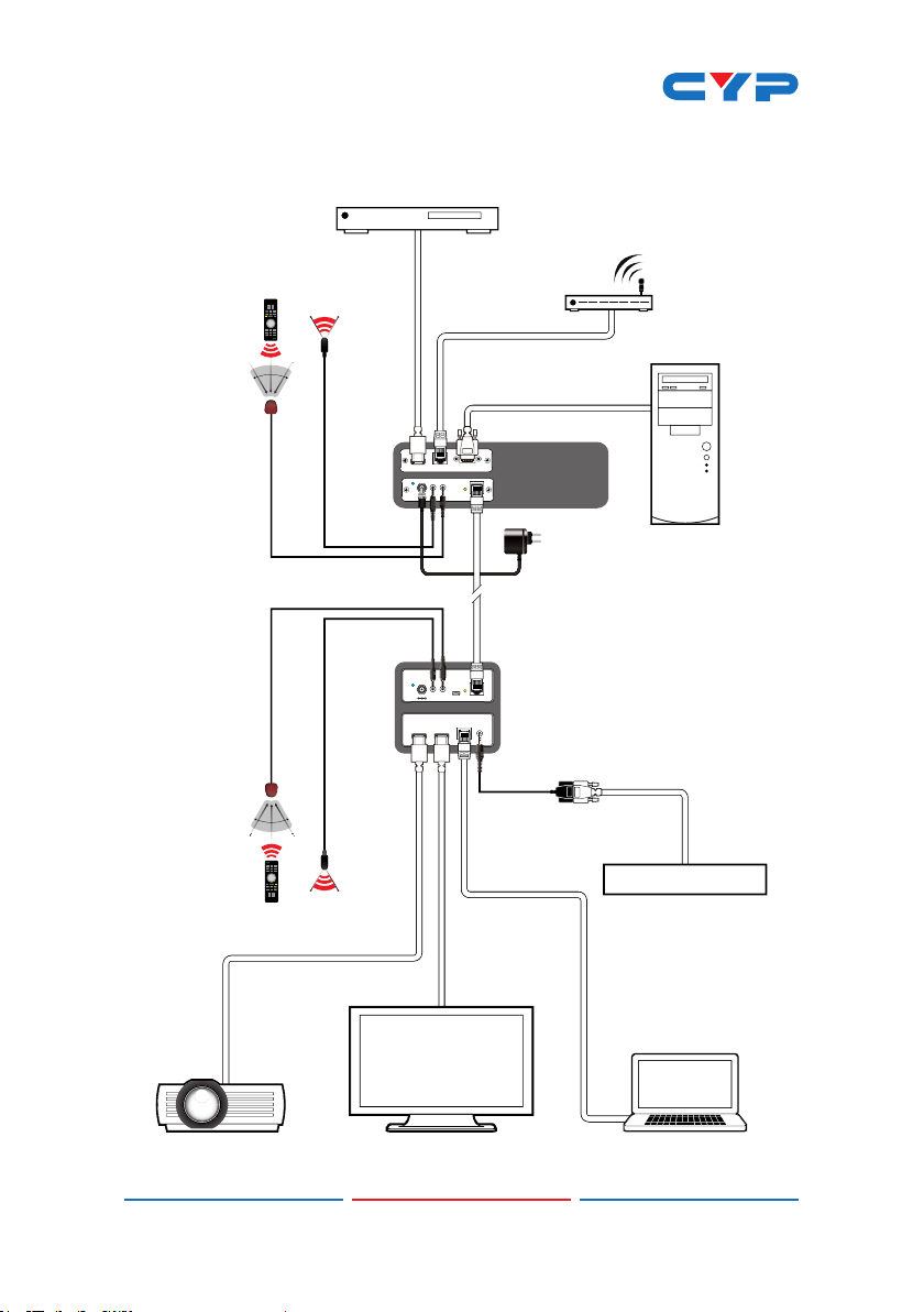
7. CONNECTION DIAGRAM
mmm
m
Blu-ray Player
60°
Extender
Extender
Router
(with Internet
Connection)
7m3m 3m
1.5m
HDMI
Input
60°
LAN
Serving
RS-232
Transmitter
RS-232 In
HDMI In
LAN
HDMI to CAT5e/6 with LAN/IR/RS232
Link
CAT5e/6 Out
HDBaseT
Transmitter
Power
Supply
RS-232 Equipped
PC or Control
IR1 Blaster
Power
DC 24V
IR2 Extender
IR
IR
Blaster
System
Single
BLASTER
IR 2
IR 1
EXTENDER
CAT5e/6/7 IN
LINK
USB
Receiver
LAN
RS-232 OUT
CAT5e/5/7
Cable
IR
IR
Blaster
POWER
DC 24V
HDMI OUT 1 HDMI OUT 2
RS-232
60°
7m3m 3m
60°
1.5m
HDMI
Output
HDMI
Output
RS232 Equipped
Device
LAN
Serving
HD Projector PC/LaptopHDTV
6
Page 12

8. SPECIFICATIONS
8.1 Technical Specications
Video Bandwidth 340 Mbps/10.2 Gbps
Input Ports 1×CAT5e/6/7, 1×LAN, 1×IR Extender, 1×USB
Mini-B (Service only)
Output Ports 2×HDMI, 1×IR Blaster, 1×RS-232
CAT5e/6/7 Cable
Distances
HDMI Cable Distances Up to 10 meters@1080p/8-bit or 12-bit
HDMI Resolutions Up to 4K2K (3840×2160@30 Hz/4096×2160@
IR Frequency 30~50 kHz
Power Supply 24 V/1.25 A DC (US/EU standards, CE/FCC/
ESD Protection Human-body Model:
Dimensions 100 mm (W)×92 mm (D)×35 mm (H)/Jacks
Weight 282 g
Chassis Material Metal
Silkscreen Color Black
Operating Temperature 0 ˚C~40 ˚C/32 ˚F~104 ˚F
Storage Temperature −20 ˚C~60 ˚C/−4 ˚F~140 ˚F
Relative Humidity 20~90 % RH (non-condensing)
Power Consumption 10 W
Up to 100 meters
24 Hz)
UL certied)
±8kV (air-gap discharge)
±4kV (contact discharge)
Excluded
100 mm (W)×112 mm (D)×38 mm (H)/Jacks
Included
7
Page 13

8.2 CAT5e/6/7 Cable Specications
CABLE TYPE RANGE PIXEL
CLOCK
RATE
CAT5e/6/7 100 m ≤225 MHz ≤5.3 Gbps
70 m >225 MHz >5.3 Gbps
CAT6a/7 100 m >225 MHz >5.3 Gbps
VIDEO DATA
RATE
(HD Video)
(Ultra HD
Video)
(Ultra HD
Video)
9. ACRONYMS
ACRONYM COMPLETE TERM
4K2K 3840×2160 or 4096×2160 Resolutions
SUPPORTED VIDEO
Up to 1080p,
60 Hz,36 bits, 3D
(data rates lower
than 5.3 Gbps or
below 225 MHz
TMDS clock)
4K2K, 30 Hz video
formats
4K2K, 30 Hz video
formats
DTS Digital Theater System
EDID Extended Display Identication Data
HDCP High-bandwidth Digital Content Protection
HDMI High-Denition Multimedia Interface
HDTV High-Denition Television
8
Page 14

Page 15

Page 16

CYPRESS TECHNOLOGY CO., LTD
Home page: http://www.cypress.com.tw
20130711 MPM-CHDBR-2HE
 Loading...