

Page 1

COMPLETE
MANUAL
Model
Revision:
Chameleon CTM-15X
modem
Firmware 1.2.0
Revision 1.0
3066 Beta Avenue Burnaby, B.C. V5G 4K4
Phone: 604.294.4465
Fax: 604.294.4471
support@cypress.bc.ca
Page 2

Notice
Due to the nature of wireless communication the reception or transmission of data can never be
guaranteed. Data may be delayed, corrupted or never received. Data transfer problems are rare with
well-constructed and configured wireless networks used in conjunction with devices such as the CTM-15X
wireless data device. Cypress Solutions Inc. accepts no responsibility for damages of any kind including
but not limited to personal injury, death, or loss of property due to the delay or loss of data resulting from
the use of the CTM-15X wireless data device.
Safety & hazards
Wireless transmitters can cause interference with some critical operation equipment. For this reason it is
required that the RF portion of the CTM-15X Series wireless data device be turned off when in the vicinity
of blasting operations, medical equipment, life support equipment, or any other equipment that is
susceptible to radio interference. The CTM-15X series wireless data device must be turned off when onboard or in the vicinity of any aircraft. The FAA prohibits the use of wireless transmitter equipment at any
time during aircraft flight.
2 0BActivating Your Modem
Regulatory restrictions
CAUTION: Any modifications to the CTM-15X series wireless data device not expressly authorized by
Cypress Solutions Inc. may cause its regulatory approval status to become invalidated, thereby voiding
your authority to use the product.
The CTM-15X series wireless data device contains a wireless device approved under FCC CFR 47 part
2.1091 and Industry Canada RSS-102 rules for operation as a mobile or fixed device with its specified
antenna of gain ≤6dBi and from which a separation distance of at least 20cm (8”) must be maintained
from all persons at all times and during all modes of operation. The antenna used must not be co-located
or operated in conjunction with any other antenna or transmitter. These rules are in place to prevent any
possible hazard due to personal exposure to electromagnetic radiation.
The CTM-15X series devices are designed to operate with approved wireless cards installed. These cards
will have their own FCC and Industry Canada approval ID numbers. Contact Cypress Solutions for a
complete updated list of supported Wireless cards/modules.
Electromagnetic Interference (EMI) – United States FCC Information
This equipment has been tested and found to comply with limits for a class A digital device, pursuant to
part 15 of the FCC rules. These limits are designed to provide reasonable protection against harmful
interference in a commercial installation. This equipment generates, uses, and can radiate radio
frequency energy, and if not installed and used in accordance with the instructions, may cause harmful
© 2009 Cypress Solutions
(Revision 1.0)
Complete Manual: CTM-15X Firmware 1. 2.0
Page 3

interference to radio communication. However, there is no guarantee that harmful interference will not
occur in a particular installation. If this equipment does cause harmful interference to radio or television
reception, which can be determined by turning the equipment off and on, the user is encouraged to try to
correct the interference by one or more of the following measures:
• reorient or relocate the receiving antenna
• increase the separation between the equipment and receiver
• connect the equipment into an outlet on a circuit different from that to which the receiver is
connected
• consult the dealer or an experienced radio/TV technician for help
Electromagnetic Interference (EMI) – Canada Information
This digital apparatus does not exceed the class A limits for radio noise emissions from digital apparatus
as set out in the interference causing equipment standard entitles “Digital Apparatus”, ICES-003 of the
Department of Communications.
3 0BActivating Your Modem
Cet appareil numérique respecte les limites de bruits radioélectriques applicables aux appareils
numériques de Classe A prescrites dans la norme sur le matériel brouilleur: “Appareils Numériques”,
NMB-003 édictée par le Ministre des Communications.
Trademarks
All brand or product names, trademarks, logos, etc. used in this manual are owned by their respective
companies.
© 2009 Cypress Solutions
(Revision 1.0)
Complete Manual: CTM-15X Firmware 1. 2.0
Page 4

Notice .......................................................................................................................................................... 2
Safety & hazards ......................................................................................................................................... 2
Regulatory restrictions ................................................................................................................................ 2
Electromagnetic Interference (EMI) – United States FCC Information....................................................... 2
Electromagnetic Interference (EMI) – Canada Information ....................................................................... 3
Trademarks ................................................................................................................................................. 3
1 Activating Your Modem .......................................................................................................................... 9
1.1 Gather Account Information .............................................................................................................. 9
1.1.1 CDMA/EV-DO devices ............................................................................................................... 9
1.1.2 GSM/GPRS/HSPA devices .......................................................................................................... 9
1.2 Embedded Web Page Activation ....................................................................................................... 9
1.2.1 Automatic Activation via Modem Embedded Web Browser .................................................... 9
4 0BActivating Your Modem
1.2.2 Manual Activation via Modem Embedded Web Browser ....................................................... 10
1.3 Command Line Activation ................................................................................................................ 10
1.3.1 Automatic Activation (OTASP) ................................................................................................ 11
1.3.2 Manual Activation ................................................................................................................... 11
2 Installing Your Modem .......................................................................................................................... 12
2.1 Mounting ......................................................................................................................................... 12
2.2 Connecting the Power Cable ............................................................................................................ 14
2.3 Connecting the Ethernet Cable ........................................................................................................ 14
2.4 Mounting and Attaching the Cell Antenna ...................................................................................... 14
2.5 Mounting and Attaching the GPS Antenna ...................................................................................... 15
2.6 Serial Data Cable Connection ........................................................................................................... 15
2.7 Connecting to the I/O Port ............................................................................................................... 15
2.7.1 Output Connection .................................................................................................................. 16
2.7.2 Input Connection ..................................................................................................................... 16
3 Operating Your Modem ........................................................................................................................ 17
3.1 Automatic Power Control ................................................................................................................ 17
3.2 Power Consumption ........................................................................................................................ 18
3.3 Device Reset ..................................................................................................................................... 18
3.4 LED Indicators .................................................................................................................................. 19
3.5 Making a Wireless Network Connection ......................................................................................... 20
3.6 GPS Operation .................................................................................................................................. 20
4 Connecting to a CTM-15X Modem Locally ............................................................................................ 21
© 2009 Cypress Solutions
(Revision 1.0)
Complete Manual: CTM-15X Firmware 1. 2.0
Page 5

4.1 Ethernet ........................................................................................................................................... 21
4.2 Telnet ............................................................................................................................................... 21
4.3 Browser ............................................................................................................................................ 22
4.4 Serial ................................................................................................................................................ 23
5 Connecting to a CTM-15X Modem Remotely ....................................................................................... 24
6 List of Commands .................................................................................................................................. 25
6.1.1 A .............................................................................................................................................. 25
6.1.2 B............................................................................................................................................... 25
6.1.3 C ............................................................................................................................................... 25
6.1.4 D .............................................................................................................................................. 25
6.1.5 E ............................................................................................................................................... 26
6.1.6 F ............................................................................................................................................... 26
5 0BActivating Your Modem
6.1.7 G .............................................................................................................................................. 26
6.1.8 I ................................................................................................................................................ 26
6.1.9 L ............................................................................................................................................... 27
6.1.10 M .......................................................................................................................................... 27
6.1.11 N........................................................................................................................................... 27
6.1.12 O .......................................................................................................................................... 27
6.1.13 P ........................................................................................................................................... 28
6.1.14 R ........................................................................................................................................... 28
6.1.15 S ........................................................................................................................................... 29
6.1.16 T ........................................................................................................................................... 29
6.1.17 U........................................................................................................................................... 29
6.1.18 V ........................................................................................................................................... 29
6.1.19 W.......................................................................................................................................... 30
7 Command Reference ............................................................................................................................ 31
7.1.1 “A” Commands ........................................................................................................................ 31
7.1.2 “B” Commands ........................................................................................................................ 31
7.1.3 “C” Commands ........................................................................................................................ 32
7.1.4 “D” Commands ........................................................................................................................ 33
7.1.5 “E” Commands ........................................................................................................................ 36
7.1.6 “F” Commands ........................................................................................................................ 38
7.1.7 “G” Commands ........................................................................................................................ 40
7.1.8 “I” Commands ......................................................................................................................... 49
© 2009 Cypress Solutions
(Revision 1.0)
Complete Manual: CTM-15X Firmware 1. 2.0
Page 6

7.1.9 “L” Commands......................................................................................................................... 58
7.1.10 “M” Commands ................................................................................................................... 61
7.1.11 “N” Commands .................................................................................................................... 68
7.1.12 “O” Commands .................................................................................................................... 69
7.1.13 “P” Commands..................................................................................................................... 74
7.1.14 “R” Commands .................................................................................................................... 90
7.1.15 “S” Commands ................................................................................................................... 100
7.1.16 “T” Commands ................................................................................................................... 110
7.1.17 “U” Commands .................................................................................................................. 111
7.1.18 “V” Commands .................................................................................................................. 113
7.1.19 “W” Commands ................................................................................................................. 115
8 Report Messages ................................................................................................................................. 120
6 0BActivating Your Modem
8.1 Message Type 03, PMID ................................................................................................................. 120
8.2 Message Type 16, $GPGLL ............................................................................................................. 121
8.3 Message Type 20, PIND ................................................................................................................. 121
8.4 Message Type 21 to 26, PINA ........................................................................................................ 122
8.5 Message Type 30, PCTM ................................................................................................................ 122
8.6 Message Type 40, ID= .................................................................................................................... 123
8.7 Message Type 80, $GPGGA ............................................................................................................ 123
8.8 Message Type 82, GPRMC ............................................................................................................. 124
8.9 Message Type 84, $GPGSA ............................................................................................................ 124
8.10 Message Type 85, ULCP binary position message with GPS coordinates ................................ 125
8.11 Message Type 88, ULCP message with Acceleration/Deceleration and GPS information ....... 125
8.12 Message Type 89, ULCP binary format, Modem ID/Firmware, Revision/Odometer value ...... 126
8.13 Message Type 90, ULCP binary format, Odometer value ......................................................... 126
8.14 Message Type 98, ULCP binary format, Digital Inputs plus GPS data ....................................... 127
8.15 Message Type 100, Trimble proprietary TAIP PV message ...................................................... 127
8.16 Message Type 101, Trimble Proprietary LN message ............................................................... 128
8.17 Message Type 112, ULCP binary format, Digital input and Output states, Modem ID and GPS
data 128
8.18 Message Type 114, $PGPS ........................................................................................................ 129
8.19 Message Type 115, $PKML ....................................................................................................... 130
8.20 Message Type 116, $PPWR ....................................................................................................... 130
8.21 Message Type 117, $PRFI ......................................................................................................... 131
© 2009 Cypress Solutions
(Revision 1.0)
Complete Manual: CTM-15X Firmware 1. 2.0
Page 7

8.22 Message Type 117, $PRFI ......................................................................................................... 131
8.23 Message Type 118, $GPGSV ..................................................................................................... 132
8.24 Message Type 119, $POBDA ..................................................................................................... 132
8.25 Message Type 120, $POBDB ..................................................................................................... 133
8.26 Message Type 121, $POBDC ..................................................................................................... 133
8.27 Message Type 122, $POBDD ..................................................................................................... 134
8.28 Message Type 136, $PACCEL .................................................................................................... 134
8.29 Message Type 137, $PODO ....................................................................................................... 135
9 Email Message Format ........................................................................................................................ 135
10 MODBUS Messages ........................................................................................................................ 136
10.1 Read Digital Outputs ................................................................................................................. 136
10.2 Set Digital Output ..................................................................................................................... 137
7 0BActivating Your Modem
10.3 Read Digital Inputs .................................................................................................................... 137
10.4 Read Analog Inputs ................................................................................................................... 138
10.5 Error response .......................................................................................................................... 139
10.6 MODBUS TCP Messages ........................................................................................................... 139
11 ULCP Remote Configuration Messages.......................................................................................... 140
11.1 ULCP Message Format .............................................................................................................. 140
11.2 ULCP Remote Configuration Messages .................................................................................... 141
11.2.1 Set Digital Outputs ............................................................................................................. 141
11.2.2 NMEA GGA Query .............................................................................................................. 141
11.2.3 NMEA RMC Query ............................................................................................................. 141
11.2.4 ULCP Binary Position Query ............................................................................................... 142
11.2.5 Time Based Reporting ........................................................................................................ 142
11.2.6 Delta Position Based Reporting ......................................................................................... 143
11.3 Examples ................................................................................................................................... 144
11.3.1 1. Set all OUTPUT ports(1~4) on ........................................................................................ 144
11.3.2 2. Set Delta Position Based Reporting ............................................................................... 145
12 Technical Specifications ................................................................................................................. 145
12.1 FCC/IC Approvals ...................................................................................................................... 145
12.2 Temperature ............................................................................................................................. 145
12.3 Humidity ................................................................................................................................... 145
12.4 Vibration ................................................................................................................................... 146
12.5 Shock ......................................................................................................................................... 146
© 2009 Cypress Solutions
(Revision 1.0)
Complete Manual: CTM-15X Firmware 1. 2.0
Page 8

12.6 Sealing ....................................................................................................................................... 146
12.7 Material..................................................................................................................................... 146
12.8 Power Supply ............................................................................................................................ 146
12.9 Host Connectivity ...................................................................................................................... 146
12.10 I/O ............................................................................................................................................. 147
12.11 RF .............................................................................................................................................. 147
12.11.1 CDMA/EV-DO ..................................................................................................................... 147
12.11.2 GSM/GPRS/HSPA ............................................................................................................... 147
12.12 GPS ............................................................................................................................................ 147
12.13 Physical ..................................................................................................................................... 148
13 Technical Support .......................................................................................................................... 148
8 0BActivating Your Modem
© 2009 Cypress Solutions
(Revision 1.0)
Complete Manual: CTM-15X Firmware 1. 2.0
Page 9

1 Activating Your Modem
1.1 Gather Account Information
1.1.1 CDMA/EV-DO devices
For Sierra Wireless AC595/AC597/AC598/AC580 CDMA/EV-DO devices, the following information is
typically required:
• Phone number (10-digit MDN)
• Lock code (6-digit CSL)
• User name (number@… format)
• Password
• Dial number (usually #777)
For all other manufacturer data devices and cards, network activation of the device must be done in a
laptop prior to installing in the modem.
9 0BActivating Your Modem
1.1.2 GSM/GPRS/HSPA devices
For GSM/GPRS/HSPA devices, the following information is required:
• An activated SIM card needs to be installed in the Modem or data card
• cmd factory gsm must be entered
Note: TRU-install™ must be disabled on devices that support the TRU-install™ feature prior to
installation into the modem, or activation will not be successful
1.2 Embedded Web Page Activation
Note: Activation via the modem Embedded web browser is supported only on Sierra Wireless AC595,
AC597 Express Card, AC597/8 USB and AC580 data devices with the TRU-install™ feature disabled. For all
other devices, activate the device using a laptop
1.2.1 Automatic Activation via Modem Embedded Web Browser
On the OTASP (Over-The-Air Service Provisioning) page, click Initiate to start the OTASP processing,
depending on the programming data on the modem card, one or more of the following messages will be
displayed on the OTASP page’s status window:
• SPL Unlocked
• Authentication key has been updated
• Shared secrets data has been exchanged
© 2009 Cypress Solutions
(Revision 1.0)
Complete Manual: CTM-15X Firmware 1. 2.0
Page 10

• New NAM parameters have been downloaded
• New MDM has been downloaded
• IMSI has been downloaded
• PRL has been downloaded
During updating, if any of the above data is unsuccessful, the "OTASP Timeout" message and the "OTASP
Disconnected" message will be displayed. To retry the OTASP process, click Initiate to re-start. When the
OTASP process is complete and the provisioning parameters have been committed the "OTASP
Disconnected" message will be displayed.
Click Initiate and cycle the power on the modem.
1.2.2 Manual Activation via Modem Embedded Web Browser
On the Activate page, enter the Lock code (CSL), the Phone number (MDN), and the Mobile Identification
Number (MIN).
10 0BActivating Your Modem
CSL, MDN and MIN are all required to successfully activate the data device.
The MIN entry is provided to add support for the Wireless Number Portability (WNP).
If you were provided with a MIN from your service provider then enter the 10-digit number in the MIN
field and enter the Lock code (CSL).
If you were not provided with a MIN then copy the 10-digit number for the MDN in the MIN field and
enter the Lock code (CSL).
Click Submit and cycle the power on the modem.
1.3 Command Line Activation
Note 1: Command line activation can be via a local telnet session or console session via the modem serial
interface
Note 2: Activation via the command line interface is supported only on Sierra Wireless AC595, AC597
Express Card, AC597/8 USB and AC580 data devices with the TRU-install™ feature disabled. For all other
devices, activate the device using a laptop
There are two methods, OTASP is a single command entry and the simplest, if OTASP does not work
follow the Manual Activation instructions.
© 2009 Cypress Solutions
(Revision 1.0)
Complete Manual: CTM-15X Firmware 1. 2.0
Page 11

1.3.1 Automatic Activation (OTASP)
At # prompt, type the command:
cmd otasp and press Enter.
This command is used to perform automatic wireless network activation and updates any required
network related files that are embedded in the wireless modem. The modem responds with one or more
of the following messages:
• SPL Unlocked
• Authentication key has been exchanged
• Shared secrets data has been updated
• New NAM parameters have been downloaded
• New MDM has been downloaded
• IMSI has been downloaded
• PRL has been downloaded
11 0BActivating Your Modem
During updating, if any of the data is unsuccessful, the "OTASP Timeout" message and "OTASP
Disconnected" message will be displayed. A progress message reading "OTASP Processing" will be
displayed every 10 seconds. When the OTASP process has successfully completed and the provisioning
parameters have been committed, a message "OTASP Disconnected" message will be displayed.
1.3.2 Manual Activation
At # prompt, type the following commands:
cmd spc pppppp where pppppp is the 6 digit lock code
cmd dir nnnnnnnnnn where nnnnnnnnnn is the 10 digit MDN phone number
cmd pwrmode 2 power cycle the modem
The MIN entry is provided to add support for Wireless Number Portability (WNP) and also needs to be set
on the modem by entering the following commands:
If no MIN is provided use the MDN number provided.
cmd spc pppppp where pppppp is the 6 digit lock code
cmd dir + nnnnnnnnnn where nnnnnnnnnn is the 10 digit MIN number
cmd pwrmode 2 power cycle the modem
© 2009 Cypress Solutions
(Revision 1.0)
Complete Manual: CTM-15X Firmware 1. 2.0
Page 12

2 Installing Your Modem
2.1 Mounting
The CTM-15x is provided with a flexible mounting bracket that has eight 5mm mounting holes suitable for
#10 screws. These may be used to screw or bolt the device to a suitable surface – take care not to overtighten these screws and damage the bracket. Once this has been installed in the required location the
modem clips into the 4 tabs of the bracket. The bracket can be used as drill guide template. There are a
total of 8 mounting holes, (2, 4 hole patterns, 2 x 5.5 and 1.75 x 3.75)
12 1BInstalling Your Modem
© 2009 Cypress Solutions
(Revision 1.0)
Complete Manual: CTM-15X Firmware 1. 2.0
Page 13

13 1BInstalling Your Modem
The modem can be installed in any orientation, but it is suggested that the modem not be mounted with
the interconnect face directed upwards as this can allow liquids to enter the modem.
The modem should be mounted in an area where it is free from excessive dust and liquids.
© 2009 Cypress Solutions
(Revision 1.0)
Complete Manual: CTM-15X Firmware 1. 2.0
Page 14
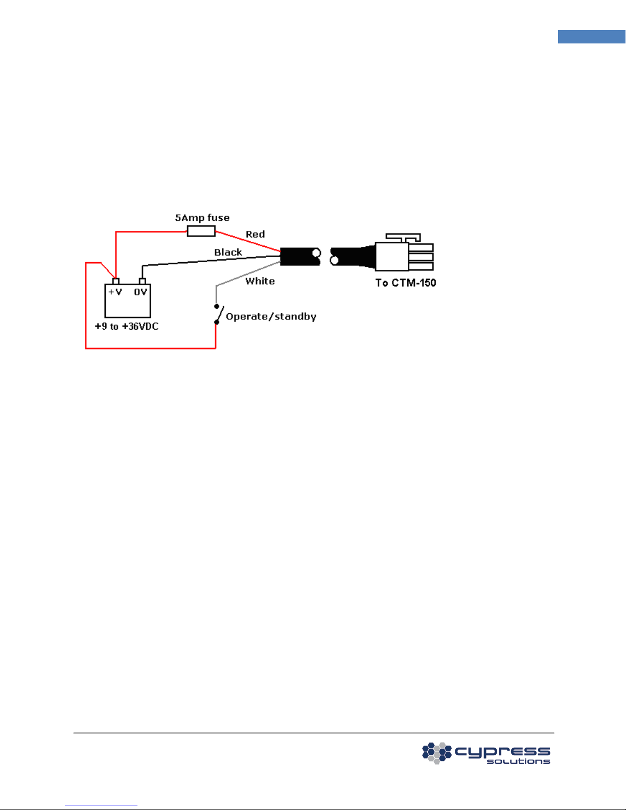
2.2 Connecting the Power Cable
The power cable has three wires:
Red +V supply (+9 to +36VDC)
Black 0V return
White Standby (+V for operation, Off for standby)
A 5 Amp “slow-blow” fuse is recommended in the +V supply line.
14 1BInstalling Your Modem
The operate/standby switch may, for example, be the accessory position on a vehicle ignition switch. In
order to minimize the acquisition time of the GPS module in the CTM-15x at power on, it is recommended
to keep the +V supply connected – this will provide the “keep-alive” power required by the GPS module
to maintain its internal almanac.
2.3 Connecting the Ethernet Cable
Plug one end of a standard Ethernet patch cable into the CTM-15x Ethernet port, and the other end into
the LAN device, PC or Ethernet peripheral. The Ethernet port is compatible with 10Base-T or 100Base-T
connection types.
2.4 Mounting and Attaching the Cell Antenna
The antenna used with the CTM-15x must be a type suitable for operation on the network for which the
modem is activated. For CDMA/EV-DO/GPRS/HSPA networks this is typically a dual band 800 Mhz and
1900 Mhz antenna.
For optimum performance the antenna should be mounted in a vertical orientation as high up as possible
and with clear line of sight in all directions. For regulatory purposes it must be mounted in such a position
as to maintain a separation distance from any person of at least 20cm (8”).
© 2009 Cypress Solutions
(Revision 1.0)
Complete Manual: CTM-15X Firmware 1. 2.0
Page 15

2
RxD
Received Data (by DTE)
CTM-15x to PC
4
DTR
Data Terminal Ready
PC to CTM-15x
The modem antenna connector is a standard SMA female type that requires the antenna cable to use a
male SMA connector. The CTM-15x can be provided with alternate antenna connector types – contact
Cypress Solutions for details.
2.5 Mounting and Attaching the GPS Antenna
The GPS antenna used with the CTM-15x (with GPS) must be an active type with gain of at least 26dB and
compatible with a 3.3 volt dc supply provided directly by the modem over the coax cable. The antenna
installation should typically be on an upper horizontal surface of a vehicle with a clear 360 degree view of
the sky.
The GPS antenna connector is a standard MCX type or SMA female depending on whether the CTM-15X
modem is PC-CARD based or Express card/module/USB based. The CTM-15x can be provided with
alternate antenna connector types – contact Cypress Solutions for details.
15 1BInstalling Your Modem
2.6 Serial Data Cable Connection
The serial data port is a standard DB9 female connector configured as Data Communication Equipment
(DCE) and is wired as per the table below.
DB9 Pin Signal Name Direction
1 DCD Data Carrier Detect CTM-15x to PC
3 TxD Transmitted Data (by DTE) PC to CTM-15x
5 GND Signal Ground
6 DSR Data Set Ready CTM-15x to PC
7 RTS Request To Send PC to CTM-15x
8 CTS Clear To Send CTM-15x to PC
9 RI Ring Indicator CTM-15x to PC
Serial data ports on most computer equipment are configured as Data Terminal Equipment (DTE) with a
DB9 male connector. A standard serial data cable will allow for direct connection of the CTM-15x to most
computer and terminal equipment. In some cases it may be necessary to insert a “null modem” or
“gender changer” in the serial data line in order to correctly connect between the devices.
2.7 Connecting to the I/O Port
The I/O port provides for the control of 4 external devices and for monitoring 6 external sensors.
Connections are made via the 12 position connector.
© 2009 Cypress Solutions
(Revision 1.0)
Complete Manual: CTM-15X Firmware 1. 2.0
Page 16

OUT1 OUT3 OUT GND IN1 IN3 IN5
1 3 5 7 9 11
2 4 6 8 10 12
OUT2 OUT4 GND IN2 IN4 IN6
2.7.1 Output Connection
The 4 outputs are configured as “open drain” which means that they can be directly connected to
energize external relays, lamps or other DC devices.
Maximum supply voltage is 36 volts, with a maximum load current of 500mA.
Recommended wire gauge for use with the connector is 16AWG. Note that the OUT GND connection is
referenced to the modem’s supply ground.
16 1BInstalling Your Modem
2.7.2 Input Connection
The 6 inputs may be configured in the modem for monitoring a digital DC voltage state or an analog DC
voltage.
For digital state monitoring the minimum input voltage is 0 volts while the maximum is 36 volts.
The threshold detection voltage is 2.5 volts with 1 volt of hysteresis. Note that the IN GND connection is
referenced to the modem’s supply ground.
© 2009 Cypress Solutions
(Revision 1.0)
Complete Manual: CTM-15X Firmware 1. 2.0
Page 17

For analog voltage monitoring the measurement range is 0 to +10 volts with 10mV resolution. The input
can withstand up to 36 volts. Note that the IN GND connection is referenced to the modem’s supply
ground.
17 2BOperating Your Modem
3 Operating Your Modem
3.1 Automatic Power Control
The supply voltage must be a minimum of 9VDC for the CTM-15x to operate. With the power applied it
will power-up in its operating mode.
Note: In some vehicle operation, when starting the engine the vehicle supply voltage will dip below 9VDC
momentarily. This will cause the modem to reset as the power dips below 9VDC. If continual operation is
required, contact Cypress Solutions for an accessory power regulator that plugs in-line with the modem
power supply. This power regulator will prevent unnecessary resets.
© 2009 Cypress Solutions
(Revision 1.0)
Complete Manual: CTM-15X Firmware 1. 2.0
Page 18

Shutdown
Only the modem’s power
The device will go back into operation mode when the
Power Consumption
Weak RF
Strong RF
Weak RF
Strong RF
The CTM-15x Chameleon device has two power modes:
Mode Description Mode change event
Operation In this mode the device is fully
powered up and ready to receive
or make network connections
The device will go back into shutdown mode when the
ignition/standby signal is deactivated or upon expiry of
the power ON timer as configured.
18 2BOperating Your Modem
management circuits are
operating.
ignition/standby signal is activated, an input event
occurs, or upon expiry of the power OFF timer as
configured.
The CTM-15x can be configured to remain on for a defined period after the standby/ignition signal has
been turned off. This enables the modem to continue sending position reports or be used for data
operations even after the vehicle ignition has been switched off – e.g. for short duration driver breaks.
When in its power shutdown mode the modem may be configured to resume full operation by either the
standby/ignition signal becoming active, an input event occurring, or the power OFF timer expiring.
3.2 Power Consumption
The power consumption of the CTM-15x modem will depend on its supply voltage, its current operating
function and its RF environment.
The following table is provided to assist application integrators in defining the power requirements for
their specific application.
signal(12V)
Shutdown Mode 1.5mA typical 1.5mA typical 2.0mA typical 2.0mA typical
Downloading (Receive
450mA max 350mA max 220mA max 195mA max
data)
Uploading (Transmit
500mA max 390mA max 260mA max 210mA max
data)
3.3 Device Reset
The CTM-15X modem may be manually reset via the front panel using a <1mm diameter (0.04”) wire tool
(a standard paper clip). This can be used to cause the modem to reset its operation, or to enter its
standby power mode.
reset: Press and hold for 0.25 to 1 second
© 2009 Cypress Solutions
(Revision 1.0)
Complete Manual: CTM-15X Firmware 1. 2.0
signal(12V)
signal(24V)
signal(24V)
Page 19

CELL
status of the device on
device is connected
N/A
device is not
shutdown: Press and hold for 2 to 5 seconds (the PWR LED will go off at the 2-second mark). Press again
for more than 0.25 second to return to operating mode.
3.4 LED Indicators
There are five LED indicators on the CTM-15x top. These are used to show the status and operation of the
device.
19 2BOperating Your Modem
For Sierra Wireless/Kyocera Wireless CDMA/EV-DO data devices or modules:
LED Description Solid Blinking Off
PWR Power status of the
device
CELL status of the device on
the wireless network
TX/RX data is being
transmitted or
received
GPS status of the GPS
module
full operating mode
and able to connect
receiving a signal
greater than or equal
device is in shutdown
mode
receiving a signal less
than -95dBm
to -95dBm
N/A Data is being
transmitted or
received
GPS module has
obtained a valid
GPS module does not
have a valid position fix
the device has no
power
device is not
detecting a valid RF
signal
no data is being
transmitted or
received
position fix
3G indicates the type of
wireless data
connection
EV-DO Rev A (typical
downlink 450 to
800kbps)
EV-DO Rev 0 (typical
downlink 400 to 700
kbps)
1xRTT (typical
downlink 40 to 100
kbps)
For Sierra Wireless HSPA, Novatel Wireless, Option or other Manufacturer devices:
LED Description Solid Blinking Off
PWR Power status of the
device
the wireless network
© 2009 Cypress Solutions
(Revision 1.0)
Complete Manual: CTM-15X Firmware 1. 2.0
full operating mode
and able to connect
to the wireless
network
device is in shutdown
mode
the device has no
power
connected to the
wireless network
Page 20

20 2BOperating Your Modem
TX/RX data is being
transmitted or
received
GPS status of the GPS
module
3G indicates the type of
N/A Data is being
transmitted or
received
GPS module has
obtained a valid
position fix
GPS module does not
have a valid position
fix
N/A N/A N/A)
no data is being
transmitted or
received
wireless data
connection
3.5 Making a Wireless Network Connection
The CTM-15X will attempt to connect to the wireless network whenever power is applied, when
configured with cmd mode 2 (default)
If no wireless network connection is available the IP address will be given as 0.0.0.0. This can be queried
using cmd ipadr For Sierra Wireless RF devices, wireless signal strength information can be queried using
cmd rssi. These values for both 1x and EV-DO are given in dBm with range typically -60dBm (very good) to
-105dBm (weak).
With the wireless network connection active you may now open Windows® applications that will make
use of this connection – this includes email, web browsers, and VPN connections.
3.6 GPS Operation
The GPS module in the CTM-15X Modem will continuously track the unit’s position whenever power is
applied and the GPS antenna has a clear view of the sky. The time taken for the module to achieve a valid
positional fix is determined by the previous state of the unit:
For a “cold” start (after all power is applied to the modem) the acquisition time typically will be less than
50 seconds.
For a “warm” start (standby power is maintained to the CTM-15x) the acquisition time will typically be
less than 38 seconds.
For reacquisition (after the GPS module has temporarily lost signal) the time to acquire a valid position fix
is typically less than 2 seconds.
The GPS information can be sent by the device as a message in any of the configured reports.
The GPS receiver uses the WGS-84 datum.
© 2009 Cypress Solutions
(Revision 1.0)
Complete Manual: CTM-15X Firmware 1. 2.0
Page 21

4 Connecting to a CTM-15X Modem Locally
The CTM-15X modem has 2 interface ports available for configuration:
• Ethernet
• Serial
4.1 Ethernet
The ethernet port supports a telnet session and an internet browser session.
Note: If your PC or Laptop is part of an existing network, you may have to disable/reconfigure your
existing network settings.
4.2 Telnet
21 3BConnecting to a CTM-15X Modem Locally
With the device powered up and connected directly to a PC with an Ethernet cable, access the command
prompt:
Start/All Programs/Accessories/Command Prompt
Enter the command:
telnet 192.168.1.1 (this is the local IP address of the CTM-15x )
The CTM-15x will respond with its login prompt:
© 2009 Cypress Solutions
(Revision 1.0)
Complete Manual: CTM-15X Firmware 1. 2.0
Page 22

At the login prompt, type in admin (default user name). At the password prompt type in Chameleon
(default password, case sensitive).
A # prompt will be displayed indicating you now have access to the device command line interface:
22 3BConnecting to a CTM-15X Modem Locally
4.3 Browser
Open an internet browser and enter the address:
http://192.168.1.1
The browser will redirect to a web page requiring a username and password.
At the login prompt, type in admin (default user name). At the password prompt type in Chameleon
(default password, case sensitive).
After successful login you will have access to a web browser based configuration.
Notes:
• Not all device functionality is supported by the web browser interface. To access all device
commands please use the command line interface.
• The embedded web server can only be used with a single client session at any time.
© 2009 Cypress Solutions
(Revision 1.0)
Complete Manual: CTM-15X Firmware 1. 2.0
Page 23

• Only 1 I/O input signal can be set from the embedded web page.
• Both GPS and IO report web pages are limited and cannot set all conditions, including minimum
time between reports.
4.4 Serial
With the device powered up and connected directly to a PC or Laptop with a serial cable, start up a
terminal emulation program such as Windows HyperTerminal or similar application.
Configure the terminal emulation program with the following parameters:
• Data rate: 115,200 baud
• Data bits: 8
• Parity: None
• Stop bits: 1
• Flow control: None
Note: The above settings are the device default settings; they can be configured using the cmd port
command.
Press the Enter key to return the # prompt:
23 3BConnecting to a CTM-15X Modem Locally
© 2009 Cypress Solutions
(Revision 1.0)
Complete Manual: CTM-15X Firmware 1. 2.0
Page 24

5 Connecting to a CTM-15X Modem Remotely
Please note:
• It is highly recommended to test all device configuration and operation before deploying devices
to remote locations.
• Not all wireless networks offer "public" IP addresses that are remotely accessible, some are
firewall protected to allow access from either the same IP pool only or restricted IP addresses.
Contact your wireless network provider or administrator to determine what options are available.
• Some networks will force device IP addresses to change at regular intervals. Without proper
configuration, this could cause a remote device to become inaccessible if the device IP address is
not known. The CTM-15X can be configured to send a message when its IP address changes using
this command: cmd iocond
• Embedded wireless radio modules must be activated before deploying to remote locations
• Incorrectly configuring the device could cause the device to become inaccessible, take care when
issuing commands via a remote session.
There are 4 ways to configure a CTM-15X remotely:
• Telnet (most flexible, allows access to the complete repository of remote commands)
• Device Embedded Web Page (provides access to a limited sub-set of device commands, used
typically for quick configuration of basic commands)
• SMS (Allows commands to be sent to the modem via SMS, this command only applies to devices
with embedded Sierra Wireless CDMA/EV-DO revision A cards,USB modems or modules)
• ULCP (Allows configuration of digital outputs only using ULCP binary format)
• For telnet to work with a remote device cmd rmttelnet 1 must be set.
For access to the Device embedded web page, cmd rmtweb 1 must be set.
Telnet and Device Embedded Web Page Configuration
Follow the directions for telnet configuration listed in How To Connect to a CTM-15X Modem - Locally
and substitute 192.168.1.1 with the known IP address of the remote device.
SMS configuration
No configuration of the CTM-15X is required for the modem to accept SMS commands.
The commands via SMS feature is supported only on CTM15x modems installed with Sierra Wireless
cards and running firmware release R1.2.0. This feature is built into the firmware and no additional
modem configuration is required to enable commands via SMS.
CTM-15X commands may be issued via a SMS text message sent from a mobile phone or from a cell
phone carrier’s web site for execution on the CTM15x modem upon receiving the SMS message. One or
more commands may be included in the body of a SMS text message up to a maximum message size of
166 characters. The destination of such a SMS message is the phone number of the modem, which may
be obtained by entering cmd dir from a Telnet or serial port console session.
24 4BConnecting to a CTM-15X Modem Remotely
© 2009 Cypress Solutions
(Revision 1.0)
Complete Manual: CTM-15X Firmware 1. 2.0
Page 25

Message format for CTM15x commands via SMS:
NNNN:<command> <parameters> … NNNN:<command> <parameters> … (up to 166 characters)
Where:
NNNN is the last 4 digits of the modem's ESN
<command> is the command to be executed. cmd should not be included in <command> and commands
do not have to be separated by a linefeed (<CR><LF>)
<parameters> are the parameters for each command
Example: If the last 4 digits of the modem’s ESN are 1234
Two commands separated by a space in SMS message
1234:gpsremip 2 123.456.78.900 1234:save
Three commands separated by <CR><LF> for each line of the SMS message:
1234:gpsremip 2 123.456.78.900
1234:gpsremport 2 15000
1234:save
ULCP configuration
ULCP configuration is performed by sending properly formatted binary messages to port 6100 of the
remotely connected device.
see ULCP Remote Configuration Messages for message format.
25 5BList of Commands
6 List of Commands
6.1.1 A
apn (set carrier access-point name) (see pg. 31)
6.1.2 B
boomreport (set the boom tracker report) (see pg. 31)
6.1.3 C
confupgrade (configures the modem for automatic configuration capability) (see pg. 32)
ctmsts (CTM status) (see pg. 33)
6.1.4 D
dir (set NAM phone number,MDN,MIN) (see pg. 33)
dout (digital outputs) (see pg. 34)
© 2009 Cypress Solutions
(Revision 1.0)
Complete Manual: CTM-15X Firmware 1. 2.0
Page 26

dyndns (dynamic DNS) (see pg. 35)
6.1.5 E
emailsrv (set email server) (see pg. 36)
enghours (calculate engine hours) (see pg. 36)
enghrmode (used to configure enghours command) (see pg. 37)
esn (electronic serial number) (see pg. 37)
ethernet (Enable/Disable Ethernet services) (see pg. 38)
6.1.6 F
factory (restores modem settings to factory default settings) (see pg. 38)
firewall (Firewall – Port forwarding) (see pg. 39)
26 5BList of Commands
6.1.7 G
gpsaccel (GPS report trigger for hard acceleration and deceleration events) (see pg. 40)
gpsaddmes (add GPS messages to a report) (see pg. 40)
gpscond (GPS report trigger conditions) (see pg. 41)
gpsdelmes (delete GPS message) (see pg. 43)
gpsemail (GPS email address) (see pg. 43)
gpsgga (GPS GGA message) (see pg. 44)
gpslocport (GPS local port) (see pg. 44)
gpsmes (GPS messages) (see pg. 45)
gpsremip (GPS remote IP) (see pg. 45)
gpsremport (GPS remote port) (see pg. 46)
gpsrep (GPS reporting) (see pg. 46)
gpsrmc (GPS RMC message) (see pg. 48)
gpssms (set destination of GPS SMS report) (see pg. 48)
6.1.8 I
igncond (ignition report trigger conditions) (see pg. 49)
ignreport (set ignition trigger report) (see pg. 50)
input (query input channels status) (see pg. 50)
insetup (input setup) (see pg. 51)
ioaddmes (add IO message) (see pg. 52)
iocond (IO report trigger conditions) (see pg. 52)
iodelmes (delete IO message) (see pg. 53)
ioemail (IO email address) (see pg. 54)
iolocport (IO local port) (see pg. 54)
iomes (IO messages) (see pg. 54)
ioremip (IO remote IP address) (see pg. 55)
© 2009 Cypress Solutions
(Revision 1.0)
Complete Manual: CTM-15X Firmware 1. 2.0
Page 27

ioremport (IO remote port) (see pg. 55)
iorep (IO reporting) (see pg. 56)
iosms (set destination of IO SMS report) (see pg. 57)
ipadr (IP address) (see pg. 57)
6.1.9 L
landhcp (LAN DHCP server settings) (see pg. 58)
landns (LAN DNS nameserver settings) (see pg. 58)
lanip (IP address of modem on LAN) (see pg. 59)
lannetmask (Netmask of modem on LAN) (see pg. 60)
lanrepip (LAN IP address for local reporting) (see pg. 60)
27 5BList of Commands
6.1.10 M
mip (mobile IP) (see pg. 58)
modbusadd (add MODBUS TCP slave, serial slave or self slave, query MODBUS slave gateway list) (pg. 61)
modbusctm130 (enable backward compatibility with CTM13x MODBUS messages over-the-air) (pg. 63)
modbusdel (delete MODBUS entry) (see pg. 63)
modbusidmap (set up MODBUS ID to modem IP:port map) (see pg. 64)
modbusmode (sets the MODBUS gateway mode) (see pg. 65)
modbusport (sets the MODBUS port number) (see pg. 66)
mode (sets connection mode) (see pg. 66)
modemid (assign modem ID) (see pg. 67)
6.1.11 N
netwd (Network watchdog) (see pg. 68)
6.1.12 O
obdcond (OBD report trigger conditions) (see pg. 69)
obddata (Display data obtained from OBDII transmitter) (see pg. 71)
obdreport (Set report for OBD trigger) (see pg. 71)
obdsp (Sets protocol used by OBDII transmitter) (see pg. 72)
odometer (GPS odometer) (see pg. 73)
otasp (Over-The-Air Service Provisioning) (see pg. 73)
© 2009 Cypress Solutions
(Revision 1.0)
Complete Manual: CTM-15X Firmware 1. 2.0
Page 28

6.1.13 P
pad (manual PAD initiation) (see pg. 74)
padecho (PAD echo mode) (see pg. 75)
padesc (PAD escape sequence) (see pg. 75)
padesct (PAD escape guard time) (see pg. 76)
padfwdc (PAD forwarding character) (see pg. 76)
padfwdl (PAD forwarding length) (see pg. 77)
padfwdt (PAD forwarding time) (see pg. 78)
padip (PAD IP address) (see pg. 78)
padmode (PAD mode) (see pg. 79)
padport (PAD port number) (see pg. 80)
padreset (PAD reset) (see pg. 81)
padsvct (PAD server connection cut-off timer) (see pg. 81)
pendantreport (set pendant report) (see pg. 82)
ping (pings a specific IP address) (see pg. 83)
pobda-pobdd (OBDII reports) (see pg. 83)
port (serial port settings) (see pg. 84)
ppp (Local Point to Point Protocol connection) (see pg. 85)
pswd (sets password used for wireless network access via simple IP) (see pg. 85)
pupcond (power up report trigger conditions) (see pg. 86)
pupreport (set power up report) (see pg. 86)
pwrmode (power mode) (see pg. 86)
pwrsdwn (power shutdown) (see pg. 87)
pwrvcct (supply voltage threshold) (see pg. 88)
pwrwoe (power wake on event) (see pg. 89)
28 5BList of Commands
6.1.14 R
ratesel (Rate select for selected data devices/modules only) (see pg. 90)
ratetmr (Rate Timer, Sierra Wireless CDMA/EVDO only ? ) (see pg. 91)
repaddmes (add messages to a report configuration, display report configuration messages) (see pg. 91)
repdelmes (delete messages from a report configuration) (see pg. 92)
repemail (configure report email address) (see pg. 93)
replocport (configure report local port) (see pg. 94)
repremip (configure report remote IP address) (see pg. 94)
repremport (configure report remote port) (see pg. 95)
repsms (configure report SMS address) (see pg. 96)
reptype (configure local and remote report types, store-and-forward) (see pg. 97)
restore (restores last saved configuration) (see pg. 98)
rmtd (reverse telnet connection) (see pg. 98)
rmttelnet (remote telnet) (see pg. 99)
rmtweb (Remote web access) (see pg. 99)
rssi (RF signal strength) (see pg. 100)
© 2009 Cypress Solutions
(Revision 1.0)
Complete Manual: CTM-15X Firmware 1. 2.0
Page 29

6.1.15 S
saltreport (set salt-spreader report) (see pg. 100)
satbackup (switch to backup satellite modem) (see pg. 101)
save (saves configuration) (see pg. 102)
showconfig (displays current configuration settings) (see pg. 102)
showstate (displays modem state) (see pg. 103)
singlepc (single pc mode) (see pg. 104)
smssend (send SMS message) (see pg. 104)
smstext (SMS text message) (see pg. 105)
smsto (send SMS to) (see pg. 105)
smsview (SMS message view) (see pg. 106)
snfdelay (Store and Forward delay period before SNF starts) (see pg. 106)
snfflush (Store and Forward Flush) (see pg. 107)
snflog (Store and Forward log) (see pg. 107)
spc (service provisioning code) (see pg. 107)
speedth (speed threshold for enabling RF module of the modem) (see pg. 108)
swipereport (set swipe-card report) (see pg. 108)
syslog (system log) (see pg. 109)
29 5BList of Commands
6.1.16 T
telnetport (telnet port) (see pg. 110)
telnetpswd (password for telnet access) (see pg. 110)
telnettimeout (telnet timeout) (see pg. 111)
6.1.17 U
univwd (configure universal watchdog) (see pg. 111)
univwdtimer (set universal watchdog timer interval) (see pg. 112)
upgradesrv (set authorized IP for remote admin) (see pg. 112)
user (sets username used for wireless network access via simple IP) (see pg. 113)
6.1.18 V
vcc (supply voltage) (see pg. 113)
vcccond (supply voltage level report trigger conditions) (see pg. 114)
vccreport (set supply voltage level report) (see pg. 114)
ver (firmware version) (see pg. 115)
© 2009 Cypress Solutions
(Revision 1.0)
Complete Manual: CTM-15X Firmware 1. 2.0
Page 30

6.1.19 W
webpswd (password for web access) (see pg. 115)
wifiwd (configures Wi-Fi Watchdog) (see pg. 116)
wpanacktype (Man Down Pendant acknowledgement type) (see pg. 116)
wpanadddev (WPAN accessory add device id, query device id) (see pg. 117)
wpandelall (WPAN accessory delete all device ids) (see pg. 118)
wpandeldev (WPAN accessory delete device id) (see pg. 118)
wpanpanid (WPAN accessory set PAN id, query PAN id) (see pg. 118)
30 5BList of Commands
© 2009 Cypress Solutions
(Revision 1.0)
Complete Manual: CTM-15X Firmware 1. 2.0
Page 31

7 Command Reference
Each command is entered as:
cmd <command> <parameters>
Use a space between all parameters (no commas or other characters).
Use cmd save to save modified values to non-volatile memory.
7.1.1 “A” Commands
apn <name-of-apn>
This command configures the APN(Access Point Name) for a modem. This command is only applicable to
GSM/GPRS/HSPA devices.
cmd apn
Examples:
1. Query current APN
will query current APN value
31 6BCommand Reference
cmd apn
cmd apn internet.com
OK
2. Set APN
cmd apn newapn.com
OK
return to list of commands
7.1.2 “B” Commands
boomreport [n]
This command sets the report to be used for boom-tracker triggered reports.
n = 0 disables the report
n = 1 to 999 report number
boomreport requires the modem to be listening for traffic from the WPAN gateway, this requires cmd
mode 10 to be configured.
© 2009 Cypress Solutions
(Revision 1.0)
Complete Manual: CTM-15X Firmware 1. 2.0
Page 32

Examples:
1. Use report #2 for boom-tracker triggered reports.
cmd boomreport 2
OK
A cmd save is required for this command to take effect.
See Also: mode, repaddmes, repdelmes, repemail, replocport, repremip, repremport, repsms, reptype
return to list of commands
32 6BCommand Reference
7.1.3 “C” Commands
confupgrade script-name url username passwd
Configures the modem for over-the-air configuration by means of a custom configuration script retrieved
from a defined ftp server.
The command has one form, which requires 4 parameters:
The script file is a text file containing modem commands used to configure a modem:
For example:
cmd mode 2
cmd gpsrep 1 0 3
cmd gpscond 1 1 30
cmd gpsremip 1 123.123.123.123
cmd gpsremport 1 5005
......
....
..
script-name the name of the configuration script to fetch/run
url the address of the ftp site (e.g. cypress.bc.ca) can also be an IP address
username username to access ftp server
passwd password to access ftp server
For example:
cmd confupgrade ctm15x-config.sh cypress.bc.ca guest guestpw where ctm15x-config.sh is the script
file, cypress.bc.ca is the ftp server guest is the username of the ftp server and guestpw is the password of
the ftp server
return to list of commands
© 2009 Cypress Solutions
(Revision 1.0)
Complete Manual: CTM-15X Firmware 1. 2.0
Page 33

ctmsts n
This command is used to configure the reporting mode of the modems status report.
This status report is controlled by GPS report #11
use gpsrep, gpslocport, gpsremip, and gpsremport to configure the reporting destination.
Default destinations are: local port 6102; remote IP 0.0.0.0, remote port 6102. This report sends
messages #03 (Modem ID), #30 (Network status), #80 (NMEA GGA), and #82 (NMEA RMC).
These messages can be imported and displayed using the Chameleon Viewer software utility running on a
local or remote PC.
The report is sent every 10 seconds.
n = 0 status reporting: disabled (default)
n = 1 local reporting only
(cmd gpsrep 1 1 3 0 – to enable local reporting)
The current setting for the modem’s status report can be queried by using the ctmsts command without
parameters
Examples:
cmd ctmsts 1 switches on local status reporting
cmd ctmsts queries the current configuration of status reporting
A cmd save is required for this command to take effect.
return to list of commands
33 6BCommand Reference
7.1.4 “D” Commands
dir pppppppppp [qqqqqqqqqq]
This command sets the NAM (Number Assignment Module) value for the modem. It is a 10-digit phone
number assigned to the modem by the service provider. Use the spc command to unlock the modem first.
The NAM value may be queried by using the dir command without parameters.
This command also sets the MIN (Mobile Identification Number) value for the modem. It is a 10-digit
number assigned to the modem by the service provider. Use the spc command to unlock the modem first.
pppppppppp 10-digit phone number (MDN) to be assigned to the modem or “+” if only MIN is to be
assigned
Optional Parameter:
qqqqqqqqqq 10-digit phone number (MIN) to be assigned to the modem
Note: Previous firmware versions included cmd min for setting the MIN value of the modem. However,
cmd min has been replaced by cmd dir. Using cmd dir as shown one of the examples below are the only
ways to set the MIN value of the modem.
© 2009 Cypress Solutions
(Revision 1.0)
Complete Manual: CTM-15X Firmware 1. 2.0
Page 34

Examples:
1. Set the modem’s MDN and MIN
cmd dir 1234567890 0987654321
OK
2. Set the modem’s 10-digit number (MDN)
cmd dir 5551234567
OK
3. Set the modem’s 10-digit number (MIN)
cmd dir + 0987654321
OK
4. Query the modem’s currently assigned phone number (MDN)
34 6BCommand Reference
cmd dir
cmd dir 6049998888
OK
A cmd save is required for this command to take effect.
http://en.wikipedia.org/wiki/Number_Assignment_Module
http://en.wikipedia.org/wiki/MIN
return to list of commands
dout n x
This command is used to set the state of each of the all outputs. There are four outputs in total.
n = 1 to 4 output channel number
x = 0 sets output to off
x = 1 sets output to on
The current settings can be queried by using the dout command without parameters.
Examples:
1. Set output #2 ON
cmd dout 2 1
OK
2. Query the state of all four outputs
cmd dout
cmd dout 1 0
cmd dout 2 1
© 2009 Cypress Solutions
(Revision 1.0)
Complete Manual: CTM-15X Firmware 1. 2.0
Page 35

cmd dout 3 0
cmd dout 4 0
A cmd save is required for this command to take effect.
return to list of commands
dyndns text1 text2 text3
This command configures the modem to perform regular updates to the Dynamic Domain Name Service.
This feature creates an alias from a dynamic IP address to a static hostname allowing the modem to be
more easily accessed over the Internet for remote configuration or for end application. For this feature,
the modem requires a public IP address. By default this feature is disabled - “, ,”. This command requires
a cmd save command and power cycle for the changes to take effect.
text1 user name for the DYNDNS service.
text2 user password for the DYNDNS service.
text3 domain (hostname) name for the DYNDNS
The current settings of the DYNDNS (Dynamic Domain Name Service) can be queried by using the dyndns
command without parameters.
DYNDNS updates can be disabled by using 0 for the user name, 0 for the user password, and 0.0.0.0 for
the hostname. Note that after disabling DYNDNS updates, the hostname will continue to point to the last
IP address of the modem. For instructions on clearing the IP address associated with the hostname,
please refer to DYNDNS documentation for details on using the offline hostname feature.
Examples:
1. Set the user name and password and the domain name
35 6BCommand Reference
cmd dyndns cypressdemo cypress cypresscamera2.dyndns.org
OK
2. Disable DYNDNS updates
cmd dyndns 0 0 0.0.0.0
OK
3. Query the modem’s setting for this setting
cmd dyndns
cmd dyndns cypressdemo cypress cypresscamera2.dyndns.org
OK
A cmd save is required for this command to take effect.
© 2009 Cypress Solutions
(Revision 1.0)
Complete Manual: CTM-15X Firmware 1. 2.0
Page 36

http://en.wikipedia.org/wiki/Dyndns
http://www.dyndns.com/
return to list of commands
7.1.5 “E” Commands
emailsrv a.a.a.a
This command is used to set the IP address of the SMTP email server that will be used by the modem for
sending email reports.
The commands gpsrep, ignreport, and reptype are used to enable email reporting.
a.a.a.a = 0.0.0.0 to 255.255.255.255 IP address of the email server to be used for email reports. Default =
0.0.0.0 The current email server IP address can be queried by using the emailsrv without parameters.
Examples:
1. Set the email server IP address to 100.120.10.10
36 6BCommand Reference
cmd emailsrv 100.120.10.10
OK
2. Query current email server
cmd emailsrv
cmd emailsrv 100.120.10.10
OK
A cmd save is required for this command to take effect.
return to list of commands
enghours xxxx n
Since total engine hours data is not available through standard OBD2 interface, Total engine hours must
be calculated using other methods.
When a modem is installed in a vehicle and the current vehicle engine hours are known, the current
engine hours will need to be programmed.
This can be done through the following command:
cmd enghours xxxx n
© 2009 Cypress Solutions
(Revision 1.0)
Complete Manual: CTM-15X Firmware 1. 2.0
Page 37

xxxx last 4 digits of the ESN of the modem.
n Total engine hours in hours (0-999999.99).
The current value of engine hours can be queried using cmd enghours without parameters and is shown
in hours.
The modem must be configured to enable engine hours counting using the enghrmode command.
Note that ESN is available on some card models only and is set to 0000000000 in all other cases.
Examples:
1. Set the engine hours to 2501 for a modem with an ESN 55555551234
cmd enghours 1234 2501
OK
return to list of commands
37 6BCommand Reference
enghrmode n
cmd enghrmode n
where n:
0 Disabled (Default, Engine hours can still be obtained if vehicle has J1939 capability)
1 Use ignition input only
2 Use OBD2 input only
3 Use combination of ignition and OBD2 inputs
A cmd save is required for this command to take effect.
return to list of commands
esn
This command queries the 32 bit ESN (Electronic Serial Number) of the embedded wireless network
access device.
The ESN is read only and cannot be altered.
Example:
1. Query the 11 digit ESN in decimal format
© 2009 Cypress Solutions
(Revision 1.0)
Complete Manual: CTM-15X Firmware 1. 2.0
Page 38

cmd esn
12345678901
OK
http://en.wikipedia.org/wiki/Electronic_Serial_Number
return to list of commands
ethernet x
This command is used to enable or disable the Ethernet services of the modem.
Ethernet services are enabled by default whenever a cmd factory is issued.
x = 0 disable Ethernet services
x = 1 enable Ethernet services
Examples:
1. Disable Ethernet services
38 6BCommand Reference
cmd ethernet 0
OK
A cmd save is required for this command to take effect.
return to list of commands
7.1.6 “F” Commands
factory
Restores the modem configuration to the factory defaults.
The only parameter for factory is gsm, cmd factory gsm will configure a modem for use on the
GSM/GPRS/HSPA network once a compatible GSM/GPRS/HSPA data device module/card has been
installed in the modem.
Restoring the modem configuration to its factory defaults should not be performed while remotely
accessing a modem. You will not be able to remotely access the modem via Telnet or the embedded
Web server after issuing this command.
Example:
1. Restore modem to factory configuration
© 2009 Cypress Solutions
(Revision 1.0)
Complete Manual: CTM-15X Firmware 1. 2.0
Page 39

cmd factory
OK
return to list of commands
firewall n eeeee lllll t iii.iii.iii.iii s
This command is used to setup the port forwarding configuration of the modem.
Up to 10 port forwarding configurations can be set.
The local IP address will default to 192.168.1.X, where X is extracted from iii.iii.iii.iii and 192.168.1 is
extracted from the IP address in the LAN Configuration setting.
n = 1 to 10 port forwarding number
eeeee = 0 to 65535 external port number to forward to
lllll = 0 to 65535 local port number to forward to
t = 0 disable
t = 1 UDP
t = 2 TCP
t = 3 both UDP and TCP
iii.iii.iii.iii = 0.0.0.0 to 255.255.255.255 local IP address to forward to
s = 0 disable forwarding
s = 1 enable forwarding
The current port forward settings can be queried by using firewall without parameters.
Note that LAN IP addresses used in port forwarding rules must match the LAN subnet as configured using
lanip, lannetmask, and lanrepip.
Examples:
1. Set port forwarding #1 to forward data destined for port 8080 (same external & local port number), on
both using UDP and TCP protocol to IP 192.168.1.20 and enabled
39 6BCommand Reference
cmd firewall 1 8080 8080 3 192.168.1.20 1
OK
2. Set port forwarding #2 to forward data destined for external port 42375 and redirect it to local port
5001, on UDP protocol to IP 192.168.1.20 and enabled.
cmd firewall 2 42375 5001 1 192.168.1.20 1
OK
3. Query the current firewall configuration
cmd firewall
cmd firewall 1 8080 8080 3 192.168.1.20 1
OK
© 2009 Cypress Solutions
(Revision 1.0)
Complete Manual: CTM-15X Firmware 1. 2.0
Page 40

A cmd save is required for this command to take effect.
return to list of commands
7.1.7 “G” Commands
gpsaccel n a d
Sets the GPS report triggers for capturing hard acceleration and deceleration events.
Reports will be triggered if the instantaneous acceleration is greater than a or the instantaneous
acceleration is less than d.
The default thresholds are 0 km/h/s for acceleration and 0 km/h/s for deceleration.
n = 1 to 8 GPS report number
a acceleration threshold in km/h/s
d deceleration threshold in km/h/s
Examples:
1. Send GPS report #7 whenever acceleration is greater than 10 km/h/s or deceleration is less than -10
km/h/s
40 6BCommand Reference
cmd gpsaccel 7 10 -10
OK
A cmd save is required for this command to take effect.
return to list of commands
gpsaddmes n x [x2] [x3] [x4]
Adds messages to a GPS report. 4 messages can be included in a single report. Duplicate messages cannot
be included in a report.
Messages will be sent in a report in the same order that they are added with this command.
ULCP header messages will be sent as individual UDP packets, NMEA format messages will be combined
into a single packet.
n = 1 to 8 GPS report number
x message type to be added, valid message types must be used - see CTM-15X message list
Examples:
1. Adds message #16 – GPS NMEA GLL – to GPS report #4
© 2009 Cypress Solutions
(Revision 1.0)
Complete Manual: CTM-15X Firmware 1. 2.0
Page 41

cmd gpsaddmes 4 16
OK
2. Query messages for GPS report #4
cmd gpsaddmes 4
cmd gpsaddmes 4 16 80 82 0
OK
A cmd save is required for this command to take effect.
See also: gpsrep, gpsdelmes, gpslocport, gpsremip, gpsremport, gpsemail, gpssms
return to list of commands
41 6BCommand Reference
gpscond n b t [d] [ms Ms] [h hs] [mt]
Sets the condition(s) that will trigger a GPS report.
The conditional operator is used to indicate how all following parameters will be used to determine if a
report is triggered.
The mt parameter must be used at the end if all other optional parameters are entered.
The default condition for report #11 is 11 1 10 (these can be changed, the first three parameters are valid
for report #11 ONLY).
n = 1 to 8 GPS report number
b = 0 conditional operator for all following parameters: Off
b = 1 conditional operator for all following parameters: AND
b = 2 conditional operator for all following parameters: OR
t = 0 timeout disabled
t = 1 to 65535 timeout in seconds
Optional parameters:
d = 0 to 65535 distance traveled threshold in meters
ms = 0 to 65535 low speed threshold in kph – use with Ms
Ms = 0 to 65535 high speed threshold in kph – use with ms
h = 0 to 359 heading change in degrees – use with hs
hs = 0 65535 minimum speed threshold to make heading measurement valid, in kph – use with h
mt = 0 to 65535 maximum reporting rate in seconds (minimum time between reports)
The current condition(s) for a report can be queried by using the gpscond n command. If n is blank, all
GPS reports will be queried.
Examples:
1. Send report #1 every 60 seconds
© 2009 Cypress Solutions
(Revision 1.0)
Complete Manual: CTM-15X Firmware 1. 2.0
Page 42

cmd gpscond 1 1 60
OK
2. Send report #2 every 60 seconds AND distance is greater than 50 metres
cmd gpscond 2 1 60 50
OK
3. Send report #4 every 60 seconds AND the distance traveled is greater than 50 metres AND the speed is
between 20kph and 60kph
cmd gpscond 4 1 60 50 20 60
OK
4. Send report #5 every 60 seconds OR when distance traveled is greater than 50 metres OR speed is
greater than 60kph, OR if the heading changes by more than 45 degrees, with a maximum report rate of
one every 10 seconds
42 6BCommand Reference
cmd gpscond 5 2 60 50 60 200 45 10 10
OK
5. Send report #6 only when distance traveled is greater than 0 metres AND the speed is between 0kph
and 5kph AND with a maximum report rate of one every 7 seconds
cmd gpscond 6 1 0 0 0 5 0 0 7
OK
6. Query the conditions used to trigger all GPS reports
cmd gpscond
cmd gpscond 1 1 30 0 0 0 0 0 0
cmd gpscond 2 1 30 0 0 0 0 0 0
cmd gpscond 3 2 10 10 0 0 0 0 0
OK
7. Query the conditions used to trigger GPS report #4
cmd gpscond 4
cmd gpscond 4 1 0 0 0 5 0 0 7
OK
A cmd save is required for this command to take effect.
return to list of commands
© 2009 Cypress Solutions
(Revision 1.0)
Complete Manual: CTM-15X Firmware 1. 2.0
Page 43

gpsdelmes n x
This command is used to delete a message type (or all messages) from a GPS report.
n = 1 to 8 GPS report number
x message type to be deleted (0 to delete all messages)
Examples:
1. Delete message type #16 from GPS report #1
cmd gpsdelmes 1 16
OK
2. Delete all messages from GPS report #4
cmd gpsdelmes 4 0
OK
A cmd save is required for this command to take effect.
See also: gpsrep, gpslocport, gpsremip, gpsremport, gpsemail, gpssms
43 6BCommand Reference
return to list of commands
gpsemail n <email address>
Sets the email address that the GPS report will be sent to (if configured for email using gpsrep).
Up to 8 email addresses may be configured – one for each of the 8 GPS reports. The default email address
is blank.
Note that an email server is required – see emailsrv.
n = 1 to 8 GPS report number
<email address> = name@domain email address to which the report will be sent
(leave blank to clear the address)
The current email address configured for all GPS reports can be queried by using the gpsemail command
without parameters.
Examples:
1. Set the destination email address for GPS report #1
cmd gpsemail 1 me@home.com
OK
2. Clear the email address for GPS report #1
cmd gpsemail 1
OK
© 2009 Cypress Solutions
(Revision 1.0)
Complete Manual: CTM-15X Firmware 1. 2.0
Page 44

3. Query the email address for all GPS reports
cmd gpsemail
cmd gpsemail 1 me@home.com
OK
A cmd save is required for this command to take effect.
See also: gpsrep, gpsdelmes, gpslocport, gpsremip, gpsremport, gpsaddmes, gpssms
44 6BCommand Reference
return to list of commands
gpsgga
Displays the current GPS position in NMEA0183 format.
This command is a read only command.
Example:
1. Return a current GPS NMEA format GGA message
cmd gpsgga
$GPGGA,215619.00,4948.7174,N,11928.6175,W,0,5,01.9,++00380,M,,M,,0000*58
OK
return to list of commands
gpslocport n xxxxx
Sets the port number of the local server that the GPS report will be sent to.
Up to 8 GPS reports may be configured.
The default port for report #11 is 6102.
n = 1 to 8 or 11 GPS report number
xxxxx = 0 to 65535 local port number in decimal
The current local port configuration for a GPS report can be queried by entering gpslocport n, where n is
the port number.
If n is omitted, all reports will be queried.
Examples:
1. Send report #1 to local port 5005
cmd gpslocport 1 5005
OK
© 2009 Cypress Solutions
(Revision 1.0)
Complete Manual: CTM-15X Firmware 1. 2.0
Page 45

2. Query the local port setting of all GPS reports
cmd gpslocport
cmd gpslocport 1 5005
OK
A cmd save is required for this command to take effect.
See also: gpsrep, gpsdelmes, gpsaddmes, gpslocport, gpsremip, gpsemail, gpssms
return to list of commands
gpsmes
Displays all messages associated with each GPS report.
This command is read only.
Example:
cmd gpsmes displays all messages associated with each GPS report
45 6BCommand Reference
return to list of commands
gpsremip n iii.iii.iii.iii
Sets the IP address of the remote server that the GPS report will be sent to. Up to 8 GPS reports can be
configured.
n = 1 to 8 or 11 GPS report number
iii.iii.iii.iii = 0.0.0.0 to 255.255.255.255 remote IP address in decimal
The remote IP address of a report can be queried by using gpsremip n where n is the report number.
If n is omitted, all reports will be queried.
Examples:
1. Report #1 will be sent to remote IP address 123.10.1.101
cmd gpsremip 1 123.10.1.101
OK
2. Query the remote IP address setting of all GPS reports
cmd gpsremip
cmd gpsremip 1 123.10.1.101
cmd gpsremip 2 99.99.99.99
OK
© 2009 Cypress Solutions
(Revision 1.0)
Complete Manual: CTM-15X Firmware 1. 2.0
Page 46

A cmd save is required for this command to take effect.
See also: gpsrep, gpsdelmes, gpslocport, gpsaddmes, gpsremport, gpsemail, gpssms
return to list of commands
gpsremport n xxxxx
Sets the IP port number of the remote server that the GPS report will be sent to.
Up to 8 GPS reports can be configured.
n = 1 to 8 or 11 GPS report number
xxxxx = 0 to 65535 remote port number in decimal
The current IP port configuration for a GPS report can be queried by using gpsremport n where n is the
report number.
If n is omitted, all reports will be queried.
Examples:
1. Report #1 will be sent to port 5005 on remote IP address set by gpsremip
46 6BCommand Reference
cmd gpsremport 1 5005
OK
2. Query the remote port setting of all GPS reports
cmd gpsremport
cmd gpsremport 1 7001
cmd gpsremport 2 4114
OK
A cmd save is required for this command to take effect.
See also: gpsrep, gpsdelmes, gpsaddmes, gpsremip, gpsremport, gpsemail, gpssms
return to list of commands
gpsrep n l r s
Sets the reporting type for each GPS report for the local and remote servers.
n = 1 to 8 or report 11 GPS report number
© 2009 Cypress Solutions
(Revision 1.0)
Complete Manual: CTM-15X Firmware 1. 2.0
Page 47

l = 0 disables local GPS report (default)
l = 1 asynchronous NMEA or ULCP messages over RS232
l = 2 asynchronous NMEA or ULCP messages with a ULCP header over RS232
l = 3 in-band NMEA or ULCP messages in a UDP Packet over Ethernet
l = 4 in-band NMEA or ULCP messages with a ULCP header and in individual UDP packets over Ethernet
l = 5 in-band NMEA or ULCP messages in a TCP Packet over Ethernet
r = 0 disables remote GPS report (default)
r = 3 in-band NMEA or ULCP messages in a UDP Packet
r = 4 in-band NMEA or ULCP messages with a ULCP header and in individual UDP packets
r = 5 in-band NMEA or ULCP messages in a TCP Packet
r = 6 email reports
r = 7 SMS reports
s = 0 disables the store and forward of GPS reports
s = 1 enables the store and forward of GPS reports
Note: For r = 7 (SMS reports), the total length of the report must not exceed 166 characters including
<CR> and <LF>
The current report type configuration for a GPS report can be queried by using gpsrep n where n is the
report number.
If n is omitted, all reports will be queried.
Examples:
1.Send GPS report #4 as a UDP packet over Ethernet and over the wireless link, do not store GPS reports
47 6BCommand Reference
cmd gpsrep 4 3 3
OK
2. Send GPS report #2 as a UDP packet over Ethernet and as an SMS message to the SMS destination set
using the gpssms command, and enable the store and forward of GPS reports
cmd gpsrep 2 3 7 1
OK
3. Queries the reporting method for all GPS reports
cmd gpsrep
cmd gpsrep 1 0 3 1
cmd gpsrep 2 3 3 0
cmd gpsrep 11 3 0 0
OK
A cmd save is required for this command to take effect.
See also: gpsaddmes, gpsdelmes, gpslocport, gpsremip, gpsremport, gpsemail, gpssms
© 2009 Cypress Solutions
(Revision 1.0)
Complete Manual: CTM-15X Firmware 1. 2.0
Page 48

return to list of commands
gpsrmc
Displays the current GPS position in NMEA0183 format.
This command is a read only command.
Example:
1. Return a current GPS NMEA format GGA message
cmd gpsrmc
$GPRMC,215812.00,V,4948.7177,N,11928.6161,W,000.0,000.0,280409,,*38
OK
48 6BCommand Reference
return to list of commands
gpssms n pppppppppp or <email address>
Sets the destination of the GPS report that is sent as an SMS message.
Up to 8 GPS reports may be configured. The default SMS destination is blank.
Note: SMS features are only available for specific manufacturer, RF modules, cards or devices. Please
contact Cypress Solutions for a complete list of products that support SMS functionality.
n = 1 to 8 GPS report number
pppppppppp phone number which the SMS report will be sent to. For long distance calls, a “1” needs to
be added In front of the phone number.
(leave blank to clear the phone number)
<email address> email address which the SMS report will be sent to.
(leave blank to clear the address)
The current SMS destination configured for all GPS reports can be queried by using the gpssms command
without parameters.
Examples:
1. Send GPS report #1 as an SMS message to the specified phone number
cmd gpssms 1 1234567890
OK
2. Send GPS report #2 as an SMS message to the specified email address
cmd gpssms 2 me@home.com
OK
© 2009 Cypress Solutions
(Revision 1.0)
Complete Manual: CTM-15X Firmware 1. 2.0
Page 49

3. Clear the SMS destination for GPS report #1
cmd gpssms 1
OK
4. Query the phone numbers or email addresses for all GPS SMS reports
cmd gpssms
cmd gpssms 1 1234567890
cmd gpssms 2 me@home.com
OK
A cmd save is required for this command to take effect.
See also: gpsrep, gpsaddmes, gpsdelmes, gpslocport, gpsremip, gpsremport, gpsemail
return to list of commands
49 6BCommand Reference
7.1.8 “I” Commands
igncond n a
Sets the condition(s) that would trigger an ignition report.
The state of the ignition is controlled by the "white" wire of the 3 wire power connection.
The conditional parameter, a is used to indicate how all following parameters will be used to determine if
a report is triggered.
n = 1 to 8 ignition condition number
a = 0 trigger disabled (default)
a = 1 trigger on ignition going OFF
a = 2 trigger on ignition going ON
a = 3 trigger on transition (ON->OFF or OFF->ON)
The current ignition condition(s) for can be queried by igncond n where n is the condition number.
If n is blank, all ignition conditions will be queried.
Examples:
1. Set ignition condition 1 to trigger when ignition is going OFF
cmd igncond 1 1
OK
2. Set ignition condition 2 to trigger when an ignition transition (ON to OFF or OFF to ON) is detected.
© 2009 Cypress Solutions
(Revision 1.0)
Complete Manual: CTM-15X Firmware 1. 2.0
Page 50

cmd igncond 2 3
OK
A cmd save is required for this command to take effect.
See Also: ignreport
return to list of commands
ignreport [n] [r]
This command sets the report to be used for ignition triggered reports.
Up to 8 ignition trigger reports can be configured.
n = 1 to 8 ignition trigger condition
r = 1 to 999 report number
r = 0 disables the report
Example:
1. Set report #2 for ignition trigger condition #1.
50 6BCommand Reference
cmd ignreport 1 2
OK
A cmd save is required for this command to take effect.
See Also: igncond, repaddmes, repdelmes, repemail, replocport, repremip, repremport, repsms, reptype
return to list of commands
input
Reads the value and state of all inputs. There are a total of six inputs.
Both the analog voltage (range 0 to 10 Volts) and digital state (0 for off and 1 for on) are returned.
This is a read only command.
Example:
1. Query the current status of input #1 through #6
cmd input
0.00V 0
0.00V 0
0.00V 0
© 2009 Cypress Solutions
(Revision 1.0)
Complete Manual: CTM-15X Firmware 1. 2.0
Page 51

0.08V 0
0.08V 0
0.08V 0
OK
return to list of commands
insetup n d x.x p a
Configures the six inputs. Their use as a digital or analog input can be set along with their alarm states.
Note: Voltage threshold values are accurate to one decimal place, (X.X), if additional decimal place values
are entered, they will be rounded to the nearest decimal place.
n = 1 to 6 input channel number
d = A set as analog input
d = D set as digital input
x.x = 0 to 9.9 sets the voltage threshold for alarm reporting (valid if input set as analog only, use 0.0 for
digital input)
p = P sets input polarity to positive (this also determines the alarm level)
p = N sets input polarity to negative (this also determines the alarm level)
a = 0 alarm off
a = 1 alarm on
a = 2 alarm on change state (valid for digital inputs only)
The current setup can be queried by using the insetup without parameters.
Note: When configuring insetup with a digital input, the voltage threshold parameter is ignored. The
modem's I/O module has fixed digital input thresholds of 3 V and 2 V (1 V hysteresis).
Examples:
1. Set input #2 as digital, with alarm when ON
51 6BCommand Reference
cmd insetup 2 D 0.0 P 1
OK
2. Set input #4 as analog, with alarm when > 7.5V
cmd insetup 4 A 7.5 P 1
OK
3. Query the setup parameters for all 6 inputs
© 2009 Cypress Solutions
(Revision 1.0)
Complete Manual: CTM-15X Firmware 1. 2.0
Page 52

cmd insetup
cmd insetup 1 A 0.0 N 0
cmd insetup 2 A 0.0 N 0
cmd insetup 3 A 0.0 N 0
cmd insetup 4 A 0.0 N 0
cmd insetup 5 A 0.0 N 0
cmd insetup 6 A 0.0 N 0
OK
A cmd save is required for this command to take effect.
return to list of commands
ioaddmes n x [x2][x3][x4]
Adds a message to an IO report. 4 messages can be included in a single report. Duplicate messages
cannot be included in a report.
Messages will be sent in a report in the same order that they are added.
Note that ULCP header messages will be sent as individual UDP packets – NMEA format messages will be
combined into one UDP packet.
n = 1 to 8 IO report number
x message type to be added, valid message types must be used - see message list
Example:
cmd ioaddmes 4 16 adds message type #16 – GPS NMEA GLL – to IO report #4
cmd ioaddmes 4 displays all messages associated with IO report #4
A cmd save is required for this command to take effect.
return to list of commands
52 6BCommand Reference
iocond n b t i1 i2 IP mt
Sets the condition(s) that would trigger an IO report.
The conditional parameter is used to indicate how all following parameters will be used to determine if a
report is triggered.
Use the Off setting to disable the report.
n = 1 to 8 IO report number
b = 0 conditional operator for the following parameters: Off (default)
b = 1 conditional operator for the following parameters: AND
b = 2 conditional operator for the following parameters: OR
© 2009 Cypress Solutions
(Revision 1.0)
Complete Manual: CTM-15X Firmware 1. 2.0
Page 53

t = 0 timeout disabled
t = 1 to 65535 timeout in seconds
i1 = 0 alarm on input trigger: disabled
i1 = 1 to 6 alarm on input trigger: input number
i2 = 0 alarm on input trigger: disabled
i2 = 1 to 6 alarm on input trigger: input number
IP = 0 report if change in IP address: disabled
IP = 1 report if change in IP address: enabled
mt = 0 to 65535 maximum reporting rate in seconds (minimum time between reports)
The current condition(s) for a report can be queried by using iocond n where n is the report number.
If n is blank, all IO reports will be queried.
Examples:
cmd iocond 1 1 60 sends report #1 every 60 seconds
cmd iocond 2 1 60 1 sends report #2 every 60 seconds if input #1 is in alarm
cmd iocond 3 1 60 1 2 send report #3 every 60 seconds if inputs #1 and #2 are in alarm
cmd iocond 4 2 0 0 0 1 send report #4 whenever the IP address of the modem changes – this indicates
that it has made a new network connection
cmd iocond 5 2 60 0 3 0 10 send report #5 every 60 seconds or while input #3 is in alarm but with a
maximum report rate of one every 10 seconds
cmd iocond 6 1 0 6 0 0 10 send report #6 only while input #6 is in alarm but with a maximum report rate
of one every 10 seconds
cmd iocond queries the conditions to trigger all IO reports
A cmd save is required for this command to take effect.
53 6BCommand Reference
return to list of commands
iodelmes n x
Deletes a message (or all messages) from an IO report.
n = 1 to 8 IO report number
x message type to be deleted or 0 to delete all messages
Examples:
cmd iodelmes 1 16 deletes message type #16 from IO report #1
cmd iodelmes 4 0 deletes all messages from IO report #4
A cmd save is required for this command to take effect.
return to list of commands
© 2009 Cypress Solutions
(Revision 1.0)
Complete Manual: CTM-15X Firmware 1. 2.0
Page 54

ioemail n <email address>
Sets the email address that the IO report will be sent to (if configured for email using iorep).
Up to 8 email addresses may be configured – one for each of the 8 IO reports. The default email address
is blank.
n = 1 to 8 IO report number
<email address> = name@domain email address to which the report will be sent
(leave blank to clear the email address)
The current email address can be queried for all IO reports by using the ioemail command without
parameters.
Note that an email server is required – see emailsrv
Examples:
cmd ioemail 1 me@… sets the send to email address for IO report #1
cmd ioemail 1 clears the email address for IO report #1
cmd ioemail returns the email address for all 8 IO reports
A cmd save is required for this command to take effect.
54 6BCommand Reference
return to list of commands
iolocport n xxxxx
Sets the port number of the local server that the IO report will be sent to. Up to 8 IO reports may be
configured.
n = 1 to 8 IO report number
xxxxx = 0 to 65535 local port number
The current local port configuration for an IO report can be queried by using iolocport n where n is the
report number.
If n is omitted, all reports will be queried.
Examples:
cmd iolocport 1 5005 report #1 will be sent to local port 5005
cmd iolocport queries the local port setting of all IO reports
A cmd save is required for this command to take effect.
return to list of commands
iomes
© 2009 Cypress Solutions
(Revision 1.0)
Complete Manual: CTM-15X Firmware 1. 2.0
Page 55

Displays all messages associated with each IO report.
This is a read only command.
Example:
cmd iomes displays all messages associated with each IO report
return to list of commands
ioremip n iii.iii.iii.iii
Set the IP address of the remote server that the IO report will be sent to. Up to 8 IO reports may be
configured.
n = 1 to 8 IO report number
iii.iii.iii.iii = 0.0.0.0 to 255.255.255.255 remote IP address in decimal
The current IP address for an IO report can be queried by using ioremip n where n is the report number.
If n is omitted, all reports will be queried.
Examples:
cmd ioremip 1 123.10.1.101 report #1 will be sent to remote IP address 123.10.1.101
cmd ioremip queries the remote IP address setting of all IO reports
A cmd save is required for this command to take effect.
55 6BCommand Reference
return to list of commands
ioremport n xxxxx
Sets the IP port number of the remote server that the IO report will be sent to. Up to 8 IO reports may be
configured.
n = 1 to 8 IO report number
xxxxx = 0 to 65535 remote port number
The current IP port configuration for an IO report can be queried by using ioremport n where n is the
report number.
If n is omitted, all reports will be queried.
Examples:
cmd ioremport 1 5005 report #1 will be sent to port 5005 on remote IP address set by ioremip
cmd ioremport queries the remote port setting of all IO reports
A cmd save is required for this command to take effect.
© 2009 Cypress Solutions
(Revision 1.0)
Complete Manual: CTM-15X Firmware 1. 2.0
Page 56

return to list of commands
iorep n l r s
Sets the reporting type for each IO report for the local and remote servers.
n = 1 to 8 IO report number
l = 0 disables the local report (default)
l = 1 asynchronous NMEA or ULCP messages over RS232
l = 2 asynchronous NMEA or ULCP messages with a ULCP header over RS232
l = 3 in-band NMEA or ULCP messages in a UDP Packet over Ethernet
l = 4 in-band NMEA or ULCP messages with a ULCP header and in individual UDP packets over Ethernet
l = 5 in-band NMEA or ULCP messages in a TCP Packet over Ethernet
r = 0 disables the remote report (default)
r = 3 in-band NMEA or ULCP messages in a UDP Packet
r = 4 in-band NMEA or ULCP messages with a ULCP header and in individual UDP packets
r = 5 in-Band NMEA or ULCP messages in a TCP Packet
r = 6 email reports
r = 7 SMS reports
s = 0 disables the store and forward of IO reports
s = 1 enables the store and forward of IO reports
Note: For r = 7 (SMS reports), the total length of the report must not exceed 166 characters including
<CR> and <LF>
The current report configuration for an IO report can be queried by using iorep n where n is the report
number.
If n is omitted, all reports will be queried.
Examples: cmd iorep 4 3 3 this will send IO report #4 as a UDP packet over Ethernet and over the wireless
link, and will not store IO reports
cmd iorep 2 3 7 1 this will send IO report #2 as a UDP packet over Ethernet and as an SMS message to the
SMS destination set using the iosms command, and will enable the store and forward of IO reports
cmd iorep queries the reporting method for all IO reports
A cmd save is required for this command to take effect.
56 6BCommand Reference
return to list of commands
© 2009 Cypress Solutions
(Revision 1.0)
Complete Manual: CTM-15X Firmware 1. 2.0
Page 57

iosms n pppppppppp or <email address>
Sets the destination of the IO report that is sent as an SMS message. Up to 8 IO reports may be
configured. The default SMS destination is blank.
Note: SMS features are only available for specific manufacturer, RF modules, cards or devices. Please
contact Cypress Solutions for a complete list of products that support SMS functionality.
n = 1 to 8 IO report number
pppppppppp phone number which the SMS report will be sent to. For long distance calls, a “1” needs to
be added In front of the phone number.
(leave blank to clear the phone number)
<email address> email address which the SMS report will be sent to.
(leave blank to clear the address)
The current SMS destination configured for all IO reports can be queried by using the iosms command
without parameters.
Examples:
cmd iosms 1 1234567890 sends IO report #1 as an SMS message to the specified phone number
cmd iosms 2 me@… sends IO report #2 as an SMS message to the specified email address
cmd iosms 1 clears the SMS destination for IO report #1
cmd iosms queries the phone numbers or email addresses for all IO SMS reports
A cmd save is required for this command to take effect.
57 6BCommand Reference
return to list of commands
ipadr
Queries the IP address assigned to the modem by the wireless network.
This is a read only command.
Example:
1. Query the current IP address of the modem
cmd ipadr
96.2.1.161
OK
return to list of commands
© 2009 Cypress Solutions
(Revision 1.0)
Complete Manual: CTM-15X Firmware 1. 2.0
Page 58

7.1.9 “L” Commands
landhcp aaa.aaa.aaa.aaa bbb.bbb.bbb.bbb n
Configures the LAN dynamic host configuration protocol (DHCP) server settings, specifically the range of
IP addresses to assign to DHCP users and the maximum number of DHCP users on the LAN.
aaa.aaa.aaa.aaa = 0.0.0.0 to 255.255.255.255 Starting DHCP IP address in decimal (default: 192.168.1.20)
bbb.bbb.bbb.bbb = 0.0.0.0 to 255.255.255.255 Ending DHCP IP address in decimal (default:
192.168.1.254)
n = 1 to 254 Maximum number of DHCP clients (default: 10)
This command requires a cmd save and power cycle to take effect.
Examples:
1. Assign DHCP users with IP addresses within 192.168.10.20 – 192.168.10.254 inclusive to a maximum of
15 users.
58 6BCommand Reference
cmd landhcp 192.168.10.20 192.168.10.254 15
OK
2. Query current DHCP range and number of users
cmd landhcp
cmd landhcp 192.168.1.20 192.168.1.254 10
OK
A cmd save is required for this command to take effect.
See also: landns, lanip, lannetmask, lanrepip
http://en.wikipedia.org/wiki/DHCP
return to list of commands
landns aaa.aaa.aaa.aaa bbb.bbb.bbb.bbb
Configures the DHCP DNS nameserver(s). Configure up to two DNS nameserver IP addresses.
aaa.aaa.aaa.aaa = 0.0.0.0 to 255.255.255.255 DNS nameserver 1 IP address (default: 204.174.120.45)
bbb.bbb.bbb.bbb = 0.0.0.0 to 255.255.255.255 DNS nameserver 2 IP address (default: 204.174.120.46)
Examples:
1. Configure DNS nameserver to IP address 199.199.199.199
cmd landns 199.199.199.199
OK
© 2009 Cypress Solutions
(Revision 1.0)
Complete Manual: CTM-15X Firmware 1. 2.0
Page 59

2. Query current DNS nameservers
cmd landns
cmd landns 204.174.120.45 204.174.120.46
OK
A cmd save is required for this command to take effect.
See also: landhcp, lanip, lannetmask, lanrepip
return to list of commands
lanip iii.iii.iii.iii
Sets the IP address of the modem on the LAN.
iii.iii.iii.iii = 0.0.0.0 to 255.255.255.255 LAN IP address of the modem in decimal (default: 192.168.1.1)
Note: Special care must be taken when configuring this command, if an improperly configured lanip IP
address is entered the ethernet port can be rendered unusable. Before configuring this command it is
advisable to make sure that a command console is available via the serial port, or the IP address is known
and remote telnet is enabled to allow the modem to be accessed wirelessly.
The current LAN IP address can be queried by using lanip.
Examples:
1. Set the LAN IP address of the modem to 192.168.10.1
59 6BCommand Reference
cmd lanip 192.168.10.1
OK
2. Query the LAN IP address of the modem
cmd lanip
cmd lanip 192.168.1.1
OK
This command requires a cmd save and power cycle to take effect. After taking effect, local Telnet should
be accessed via the IP address specified in the command.
See also: landhcp, landns, lannetmask, lanrepip
return to list of commands
© 2009 Cypress Solutions
(Revision 1.0)
Complete Manual: CTM-15X Firmware 1. 2.0
Page 60

lannetmask iii.iii.iii.iii
Sets the netmask of the modem on the LAN.
iii.iii.iii.iii = 0.0.0.0 to 255.255.255.255 LAN netmask of the modem in decimal (default: 255.255.255.0)
Note: Special care must be taken when configuring this command, if an improperly configured
lannetmask IP address is entered the ethernet port can be rendered unusable. Before configuring this
command it is advisable to make sure that a command console is available via the serial port, or the IP
address is known and remote telnet is enabled to allow the modem to be accessed wirelessly.
The current LAN netmask can be queried by using lannetmask.
Examples:
1. Set the LAN netmask of the modem to 255.255.0.0
cmd lannetmask 255.255.0.0
OK
2. Query the LAN netmask of the modem
60 6BCommand Reference
cmd lannetmask
cmd lannetmask 255.255.255.0
OK
This command requires a cmd save and power cycle to take effect.
See also: landhcp, landns, lanip, lanrepip
http://en.wikipedia.org/wiki/Netmask
return to list of commands
lanrepip iii.iii.iii.iii
Sets the IP address of the local server connected to the modem’s LAN that will receive local reports.
iii.iii.iii.iii = 0.0.0.0 to 255.255.255.255 LAN IP address to receive local reports in decimal (default:
192.168.1.20)
This command requires a cmd save and power cycle to take effect.
The LAN IP address of the server currently used to receive local reports can be queried by using lanrepip.
Examples:
1. Set the local reporting LAN IP address to 192.168.1.21
cmd lanrepip 192.168.1.21
OK
2. Query the LAN IP address to which local reports will be sent
© 2009 Cypress Solutions
(Revision 1.0)
Complete Manual: CTM-15X Firmware 1. 2.0
Page 61

cmd lanrepip
cmd lanrepip 192.168.1.20
OK
A cmd save is required for this command to take effect.
See also: landhcp, landns, lanip, lannetmask
return to list of commands
7.1.10 “M” Commands
mip n
Sets the Mobile IP operation of the modem.
n = 0 simple IP only (mobile IP disable)
n = 1 mobile IP preferred (default)
n = 2 mobile IP only
The current mobile IP can be queried by using the mip without parameters.
Examples:
cmd mip 1 sets the MIP option to be MIP preferred
cmd mip returns the current MIP value
A cmd save is required for this command to take effect.
http://en.wikipedia.org/wiki/Mobile_IP
61 6BCommand Reference
return to list of commands
modbusadd
This command when used without arguments is used to display all the entries in the MODBUS slave
gateway list.
Example:
cmd modbusadd displays the MODBUS list
modbusadd id nnn.nnn.nnn.nnn
This command is used when the modem is being used as a MODBUS SLAVE device.
Adds a MODBUS TCP Slave. The listening port for TCP slaves is the port number configured using
modbusport.
id = 1 to 247 MODBUS ID
nnn.nnn.nnn.nnn = 1.0.0.0 to 255.255.255.255 MODBUS slave IP address (IP address of MODBUS devices
connected to the modem's ethernet port)
© 2009 Cypress Solutions
(Revision 1.0)
Complete Manual: CTM-15X Firmware 1. 2.0
Page 62

modbusadd id n p d s m w
Adds a MODBUS Serial Slave
id = 1 to 247 MODBUS ID
n = 1200 1200 Baud
n = 2400 2400 Baud
n = 4800 4800 Baud
n = 9600 9600 Baud
n = 19200 19200 Baud
n = 38400 38400 Baud
n = 57600 57600 Baud
n = 115200 115200 Baud
p = n or N no parity
p = e or E even parity
p = o or O odd parity
d = 7 or 8 data bits
s = 1 or 2 stop bits
m = a or A ASCII transmission mode
m = r or R RTU transmission mode
w = f or F flow control, leave empty for no flow control
Note1: For MODBUS RTU configuration to function properly d = 8 must be entered. (This configuration is
in accordance with the MODBUS specification)
Note2: modbusadd will return “Invalid IP address (Sx)” followed by an “OK” if modbusadd is configured
with parameters missing or incorrect parameters. Ensure that the modbussadd parameters match those
from the above list.
modbusadd id
Adds MODBUS self slave - only one is permitted.
id = 1 to 247 MODBUS ID
Examples:
1. add TCP slave with ID 1 and IP 192.168.100.122
62 6BCommand Reference
cmd modbusadd 1 192.168.100.122
2. add itself as a MODBUS slave with ID = 3
cmd modbusadd 3
3. Add serial slave with baud 115200, no parity, 8 data bits, 1 stop bit and as ASCII transmission mode
cmd modbusadd 17 115200 N 8 1 a
4. Display the list of modbus devices.
© 2009 Cypress Solutions
(Revision 1.0)
Complete Manual: CTM-15X Firmware 1. 2.0
Page 63

TCP slave device with ID = 247, self slave device with ID = 10, serial slave device (baud 19200, no parity, 8
data, 1 stop, ASCII, no flow control) with ID = 155
cmd modbusadd
(192.168.1.20,247)
(Localhost,10)
(19200.N.8.1 A,155)
A cmd save is required for this command to take effect.
return to list of commands
modbusctm130 n
Enables MODBUS backward compatibility with the CTM13x by using MODBUS RTU encapsulated in UDP
packets for messages transmitted/received over-the-air.
The CTM13x modems only use MODBUS RTU over UDP as the over-the-air protocol for communicating
between other modems configured as MODBUS master and slave gateways.
n = 0 use MODBUS TCP for over-the-air communications (default)
n = 1 use MODBUS RTU over UDP for over-the-air communications
A cmd save, and a power cycle are required before the modem is configured to use the specified
MODBUS over-the-air protocol.
Examples:
cmd modbusctm130 1 Set MODBUS gateway to send/receive MODBUS RTU over UDP messages
cmd modbusctm130 Query the currently configured MODBUS over-the-air protocol
A cmd save is required for this command to take effect.
return to list of commands
63 6BCommand Reference
modbusdel n
Deletes an entry or all entries from the MODBUS list.
n = 0 deletes all MODBUS entries
n = 1 to 247 MODBUS ID entry
Examples:
cmd modbusdel 1 delete the entry with MODBUS ID 1
© 2009 Cypress Solutions
(Revision 1.0)
Complete Manual: CTM-15X Firmware 1. 2.0
Page 64

cmd modbusdel 0 delete all entries in the MODBUS list
A cmd save is required for this command to take effect.
return to list of commands
modbusidmap n a.a.a.a p
This command is only configured when using the modem as a MASTER GATEWAY (cmd modbusmode 1
or cmd modbusmode 2). This command returns ERROR if the modem is configured as a SLAVE GATEWAY
(cmd modbusmode 0).
This command sets up the MODBUS ID to modem IP for each remote MODBUS slave device (i.e. another
CTM15x modem configured as a MODBUS slave gateway).
The default for all entries is n 0.0.0.0. Use n 0.0.0.0 0 to erase an entry. Use 0 0.0.0.0 to erase all entries.
One entry is added at a time with a limit of up to 247 entries (each entry requires a unique ID).
To change an entry, one must first erase it then enter the changed IP address and port number.
n = 1 to 247 MODBUS ID, in decimal
a.a.a.a = 0.0.0.0 to 255.255.255.255 MODBUS slave modem IP address, in decimal(wireless modem IP
address)
p = 0 to 65535 Port that the slave modem will be listening on, in decimal
Examples:
1. Set the MODBUS master gateway to forward messages designated for the slave device with ID 1 to the
modem at 123.1.2.3, port 502
64 6BCommand Reference
cmd modbusidmap 1 123.1.2.3 502
OK
2. Clear the MODBUS ID to modem IP entry for slave ID 1
cmd modbusidmap 1 0.0.0.0 0
OK
3. Change slave ID 1 entry to the modem with an IP of 123.1.2.4
cmd modbusidmap 1 123.1.2.4 502
OK
4. Clear all MODBUS ID to modem IP entries
© 2009 Cypress Solutions
(Revision 1.0)
Complete Manual: CTM-15X Firmware 1. 2.0
Page 65

cmd modbusidmap 0 0.0.0.0
OK
5. Query all MODBUS ID to modem IP entries
cmd modbusidmap
OK
A cmd save is required for this command to take effect.
See Also: modbusctm130, modbusmode
return to list of commands
65 6BCommand Reference
modbusmode n
Sets the specified MODBUS gateway mode of the modem, specifically, the transmission mode between
the modem configured as the serial master gateway and the MODBUS serial device connected to the
modem.
n = 0 slave gateway (default)
n = 1 RTU master gateway
n = 2 ASCII master gateway
A cmd mode 6, cmd save, and a power cycle are required before the modem is fully configured in a
MODBUS mode.
Examples:
1. Set modem to be a MODBUS serial RTU master gateway
cmd modbusmode 1
OK
2. Query the currently configured MODBUS gateway mode
cmd modbusmode
cmd modbusmode 1
OK
A cmd save is required for this command to take effect.
See Also: mode
return to list of commands
© 2009 Cypress Solutions
(Revision 1.0)
Complete Manual: CTM-15X Firmware 1. 2.0
Page 66

modbusport xxxxx
Sets the listening port number for the MODBUS server and the listening port number for MODBUS TCP
slaves.
Default is 502.
xxxxx = 1 to 65535 MODBUS server port number
The current MODBUS port number can be queried by entering the modbusport command without
parameters.
Note:
If the modem is currently in MODBUS mode and any other LAN or firewall configuration commands are
set after issuing the modbusport command, then both a cmd save and a power cycle are required to
resume proper MODBUS operation.
Examples:
1.Set the MODBUS port to 12345
66 6BCommand Reference
cmd modbusport 12345
OK
2. Query the existing MODBUS port
cmd modbusport
cmd modbusport 502
OK
A cmd save and power cycle are required for this command to take effect.
See also: modbusadd, modbusdel, modbusctm130, modbusidmap, modbusmode, mode
return to list of commands
mode n
Sets the required connection mode of the modem.
n = 1 manual connection
n = 2 auto connect to the network (default)
n = 3 auto connect to the network and go directly into PPP mode
© 2009 Cypress Solutions
(Revision 1.0)
Complete Manual: CTM-15X Firmware 1. 2.0
Page 67

n = 4 auto connect to both the network and the PAD host interface
n = 5 auto connect to the network and serial LCD (future)
n = 6 auto connect to both the network and the MODBUS host interface
n = 8 auto connect to both the network and the Elmscan diagnostic tool for OBD II
n = 9 auto connect to both the network and the magnetic swipe card reader
n = 10 auto connect to both the network and the WPAN Gateway
n = 12 auto connect to both the network and the Chlorobyte Salt Spreader interface
For n = 3 to 8, a cmd save and a power cycle are required before the mode takes effect, for all others
mode settings a power cycle is not required.
To escape out of the mode (to get a command prompt – console) do the following:
mode = 3 – type EXIT, type cmd port nnnn (where nnnn is the current baud rate)
mode = 4 – type +++, wait 3 seconds, type cmd port nnnn (where nnnn is the current baud rate); Refer to
padesc and padesct for escape sequence
mode = 8 – change hyper terminal baud rate to 9600, type EXIT, change hyper terminal baud rate to
nnnn, type cmd port nnnn (where nnnn is the currently set baud rate)
The current mode setting can be queried by using the mode without parameters.
Examples:
1. Set the mode to auto connect
67 6BCommand Reference
cmd mode 2
OK
2. Query the current connection mode of the modem
cmd mode
cmd mode 2
OK
A cmd save is required for this command to take effect.
return to list of commands
modemid <string>
Assigns a user configurable ID to the modem.
If no ID is given then the modem’s 11-digit decimal ESN (if available) will be used.
If less than 11 characters is entered, trailing 0’s will be automatically inserted in message type 112.
Examples:
cmd modemid CAR1234 sets the modem ID to <CAR1234>
cmd modemid returns the currently configured modem ID
© 2009 Cypress Solutions
(Revision 1.0)
Complete Manual: CTM-15X Firmware 1. 2.0
Page 68

A cmd save is required for this command to take effect.
return to list of commands
7.1.11 “N” Commands
netwd t n
Sets the network watchdog feature.
This feature is used to listen for incoming data traffic to make sure there is network connectivity.
If no data is received within the watchdog timer time out period (t * n), the modem will disconnect from
the network and reconnect to the network. If the watchdog timer expires a second time after attempting
to reconnect unsuccessfully the first time (no data received), the modem will be power cycled.
The user will define the time interval (t) the command will use to monitor network activity. The user will
also define the number of times the command needs to see consecutive data packets (n) before the
watchdog timer expires and the command resets the network connection/device. If data is received
within this interval, the timer interval and number of times will be reset.
t = 0 disable (default)
t = 1 to 65535 time to wait for incoming data (seconds)
n = 0 to 65535 number of times the timer needs to expire before disconnecting and reconnecting to the
network
A cmd save and power cycle is required before this setting takes effect.
Typically, netwd is used in conjunction with the ping command. The ping command will generate the
network traffic that netwd will watch for.
Examples:
1. Set the timer to 10 seconds and check 6 times.
68 6BCommand Reference
cmd netwd 10 6
OK
In the above example, the command will look for incoming traffic from the network at 10 seconds
intervals. If no data traffic is detected for 6 consecutive intervals 6 x 10 = 60 sec. the command will
disconnect and reconnect to the network. If a reconnect does not resolve the issue (approx 10 seconds
reconnect time) the command will cycle the modem power completely (approx 50 seconds reconnect
time) after an additional 6 intervals of no data.
If data is received, the command will not reset the network connection and the device will operate
without interruption.
2. Query the current netwd configuration
© 2009 Cypress Solutions
(Revision 1.0)
Complete Manual: CTM-15X Firmware 1. 2.0
Page 69

cmd netwd
cmd netwd 10 6
OK
See also: ping
return to list of commands
7.1.12 “O” Commands
obdcond n b t mt [trig1 ... trig4]
Sets the condition(s) that will trigger an OBD report.
The conditional operator is used to indicate how all following parameters will be used to determine if a
report is triggered.
n = 1 to 8 OBD trigger number
b = 0 conditional operator for all following parameters: Off
b = 1 conditional operator for all following parameters: AND
b = 2 conditional operator for all following parameters: OR
t = 0 timeout disabled
t = 1 to 65535 timeout in seconds
mt = 0 to 65535 maximum reporting rate in seconds (minimum time between reports)
Optional parameters:
trigx trigger parameter x enclosed in single quotes and without spaces in between, in the form 'pid^val'
where:
pid = p1 to pb engine parameters as per OBD2/J1939 Parameters Table except for p4 and id
^ - > trigger using greater than operator
^ - = trigger using equal to operator
^ - < trigger using less than operator
val engine parameter value that sets off the trigger, in decimal nnnn.nn (refer to OBD2/J1939 Parameters
Table for allowable range of values)
Each OBD trigger condition may be configured with up to 4 trigger parameters.
The current parameter(s) for a trigger condition can be queried by using the obdcond n command. If n is
blank, all OBD trigger conditions will be queried.
Examples of OBD trigger parameters:
'p1>0' trigger is set off when p1 (vehicle speed) is greater than 0 km/h
'p2=5000' trigger is set off when p2 (engine RPM) is equal to 5000 RPM
'p8<200.75' trigger is set off when p8 (engine coolant temperature) is less than 200.75°C
69 6BCommand Reference
© 2009 Cypress Solutions
(Revision 1.0)
Complete Manual: CTM-15X Firmware 1. 2.0
Page 70

Examples:
1. Set OBD trigger #1 to send a report every 60 seconds
cmd obdcond 1 1 60
OK
2. Set OBD trigger #2 to send a report every 30 seconds AND P1 (vehicle speed) is equal to 0.0 km/h with
a maximum report rate of one every 5 seconds
cmd obdcond 2 1 30 5 'p1=0.0'
OK
3. Set OBD trigger #3 to send a report every 60 seconds OR P1 (vehicle speed) is greater than 0 km/h OR
P2 (engine RPM) is greater than 2000 with a maximum report rate of one every 5 seconds
cmd obdcond 3 2 60 5 'p1>0' 'p2>2000'
OK
70 6BCommand Reference
4. Set OBD trigger #4 to send a report only when P1 (vehicle speed) is less than 10 km/h AND P2 (engine
RPM) is equal to 0 RPM AND P7 (calculated engine load value) is equal to 0 percent AND P8 (engine
coolant temperature) is -40°C with a maximum report rate of one every 15 seconds
cmd obdcond 4 1 0 15 'p1<10.00' 'p2=0.00' 'p7=0.00' 'p8=-40.00'
OK
5. Query all the trigger conditions used for OBD reports
cmd obdcond
cmd obdcond 2 1 30 5 'p1=0.0'
cmd obdcond 3 2 60 5 'p1>0' 'p2>2000'
OK
6. Query the parameters for OBD trigger condition #3
cmd obdcond 3
cmd obdcond 3 2 60 5 'p1>0' 'p2>2000'
OK
A cmd save is required for this command to take effect.
See Also: OBD2/J1939 Parameters Table, obdreport, pobda-pobdd
return to list of commands
© 2009 Cypress Solutions
(Revision 1.0)
Complete Manual: CTM-15X Firmware 1. 2.0
Page 71

obddata
Displays the current OBD engine parameters and corresponding values obtained from the OBDII
transmitter and the time since they were last updated.
If no engine parameters have been obtained yet, the command returns ERROR
This command is read-only.
Example:
cmd obddata displays OBD engine parameters and time since they were last updated
# cmd obddata
These OBD engine parameters were updated 001 seconds ago
Timestamp : Thu Jan 1 00:14:48 1970
p1=131,p2=0,p3=40,p4=AGV-SIMULATOR 1.5
p5=0,p6=0,p7=16,p8=55
p9=384,p10=128,p12=80,p13=81.92
id=0013A200403078CF,pa=0,pb=0
OK
71 6BCommand Reference
return to list of commands
obdreport [n] [r]
This command sets the report to be used for a OBD triggered report.
n = 1 to 8 number of the OBD trigger condition
r = 1 to 999 report number
r = 0 disables the report
obdreport requires the modem to be listening for traffic from the WPAN gateway, this requires cmd
mode 10 to be configured.
Example:
1. Set report #2 for OBD triggered report #1.
cmd obdreport 1 2
OK
A cmd save is required for this command to take effect.
See Also: mode, obdcond, repaddmes, repdelmes, repemail, replocport, repremip, repremport, repsms,
reptype
return to list of commands
© 2009 Cypress Solutions
(Revision 1.0)
Complete Manual: CTM-15X Firmware 1. 2.0
Page 72

obdsp n
Sets the protocol used by the OBDII transmitter.
n = 0 Automatic
n = 1 SAE J1850 PWM
n = 2 SAE J1850 VPW
n = 3 ISO 9141-2
n = 4 ISO 14230-4 KWP (slow)
n = 5 ISO 14230-4 KWP (fast)
n = 6 ISO 15765-4 CAN (11 bit ID, 500 Kbaud)
n = 7 ISO 15765-4 CAN (29 bit ID, 500 Kbaud)
n = 8 ISO 15765-4 CAN (11 bit ID, 250 Kbaud)
n = 9 ISO 15765-4 CAN (29 bit ID, 250 Kbaud)
n = 10 SAE J1939 CAN (29 bit ID, 250 Kbaud)
n = 11 USER1 CAN (11 bit ID, 125 Kbaud)
n = 12 USER2 CAN (11 bit ID, 50 Kbaud)
The current OBDII transmitter protocol can be queried by using the obdsp command without parameters.
Note that option 0 (Automatic) only replaces OBD2 protocol options 1-9. Some vehicles may exhibit
problems with automatic protocol discovery. obdsp must specifically be set to match the protocol on
those vehicles.
Examples:
1. Set the OBDII transmitter to use the J1939 protocol
72 6BCommand Reference
cmd obdsp 10
OK
2. Query the current OBDII transmitter protocol
cmd obdsp
cmd obdsp 7
OK
A cmd save is required for this command to take effect.
return to list of commands
© 2009 Cypress Solutions
(Revision 1.0)
Complete Manual: CTM-15X Firmware 1. 2.0
Page 73

odometer n
Sets the GPS odometer.
The GPS odometer keeps track of the distance travelled in km by using GPS position data. If n is omitted,
the current value of the GPS odometer will be queried.
The maximum odometer value is 1999999 km. The odometer will roll over to 0 km when the current
odometer value exceeds the maximum.
The GPS odometer is reset to 0 km whenever one of these cases applies:
(i) n is specified as reset
(ii) n is specified as 0
(iii) cmd factory is issued.
Examples:
1. Reset the GPS odometer value to 0
73 6BCommand Reference
cmd odometer reset
OK
2. Reset the GPS odometer value to 0
cmd odometer 0
OK
3. Set the GPS odometer to 100000 km
cmd odometer 100000
OK
4. Query the current GPS odometer value in km
cmd odometer
1245 KM
OK
return to list of commands
otasp
This command is used to perform automatic wireless network activation and updates any required
network related files that are embedded in the wireless modem.
The modem responds with one or more of the following messages:
• SPL Unlocked
© 2009 Cypress Solutions
(Revision 1.0)
Complete Manual: CTM-15X Firmware 1. 2.0
Page 74

• Authentication key has been exchanged
• Shared secrets data has been updated
• New NAM parameters have been downloaded
• New MDM has been downloaded
• IMSI has been downloaded
• PRL has been downloaded
During updating, if any of the above data is unsuccessful, an OTASP Timeout message will be displayed.
A progress message OTASP Processing will be displayed every 10 seconds.
When the OTASP process has been completed, the OTASP Disconnected message will be displayed.
Example:
1. Initiate automatic wireless network activation
cmd otasp
OK
74 6BCommand Reference
return to list of commands
7.1.13 “P” Commands
pad
Initiates a packet data connection. Use this to initiate a manual PAD connection from the serial port
console. Do not use this command from telnet console!
Use cmd mode 4 to put the modem in permanent PAD mode (enter PAD automatically after a power
cycle).
Example:
1. Initiate a manual PAD packet connection to the wireless network
cmd pad
OK
See also: padecho, padesc, padesct, padfwdc, padfwdl, padfwdt, padip, padmode, padport, padreset,
padsvct
return to list of commands
© 2009 Cypress Solutions
(Revision 1.0)
Complete Manual: CTM-15X Firmware 1. 2.0
Page 75

padecho n
Sets the PAD echo mode – if echo is enabled then all data sent to the modem on its RS232 port by an
external device is echoed back to that device.
n = 0 PAD echo mode: disabled
n = 1 PAD echo mode: enabled (default) The current PAD echo mode can be queried by using the
padecho command without parameters.
Examples:
1. Disable the PAD echo – characters received on the modem’s RS232 port will not be echoed to the
connected device
cmd padecho 0
OK
2. Query the current PAD echo setting
75 6BCommand Reference
cmd padecho
cmd padecho 1
OK
A cmd save is required for this command to take effect.
See also: pad, padesc, padesct, padfwdc, padfwdl, padfwdt, padip, padmode, padport, padreset, padsvct
return to list of commands
padesc <str>
Sets the PAD escape sequence used to return to command line mode.
Default is +++.
When using the escape sequence it is necessary to wait the guard time (padesct) before entering data
Enter only the escape sequence (do not enter any other characters including <CR> or <LF>)
If PAD forwarding time (padfwdt) is set there will be a delay until the escape characters are forwarded.
The guard time (padesct) must also be honored, to allow the modem to escape from PAD mode.
<str> PAD escape sequence, 10 characters maximum, no spaces, case sensitive
The current PAD escape sequence can be queried by using the padesc command without parameters.
Examples:
1. Set the PAD escape sequence to ASCII string 12345
cmd padesc 12345
OK
© 2009 Cypress Solutions
(Revision 1.0)
Complete Manual: CTM-15X Firmware 1. 2.0
Page 76

2. Query the current PAD escape string
cmd padesc
cmd padesc +++
OK
A cmd save is required for this command to take effect.
See also: pad, padecho, padesct, padfwdc, padfwdl, padfwdt, padip, padmode, padport, padreset,
padsvct
return to list of commands
76 6BCommand Reference
padesct n
Sets the PAD escape guard time.
This is the idle time before and after the PAD escape sequence which must be present for the escape
sequence to be recognized.
n = 0 to 65535 PAD escape guard time in seconds. Default is 3 seconds.
NOTE: values greater than 8 seconds shouldn't be used in TCP PAD client mode.
The current PAD escape guard time can be queried by using the padesct command without parameters.
Examples:
1. Set the PAD escape guard time to 4 seconds
cmd padesct 4
OK
2. Query the current PAD escape guard time
cmd padesct
cmd padesct 3
OK
A cmd save is required for this command to take effect.
See also: pad, padecho, padesc, padfwdc, padfwdl, padfwdt, padip, padmode, padport, padreset, padsvct
padfwdc x
© 2009 Cypress Solutions
(Revision 1.0)
Complete Manual: CTM-15X Firmware 1. 2.0
Page 77

Sets the PAD forwarding character. Default = 13 (ASCII <enter>)
x = 0 padfwdt or padfwd will invoke sending the packet
x = 1 to 255 PAD forwarding character representing an ASCII character.
The current PAD forwarding character can be queried by using the padfwdc command without
parameters .
Examples:
1. sets the PAD forwarding character to ASCII <space>
cmd padfwdc 32
OK
2. Query the current PAD forwarding character
cmd padfwdc
cmd padfwdc 32
OK
77 6BCommand Reference
A cmd save is required for this command to take effect.
See also: pad, padecho, padesc, padesct, padfwdl, padfwdt, padip, padmode, padport, padreset, padsvct
return to list of commands
padfwdl x
Sets the maximum PAD packet length. Default = 40.
If 0 is specified then every character is sent immediately.
x = 0 sent every characters immediately
x = 1 to 1000 maximum PAD packet length
The current PAD packet length can be queried by using the padfwdl command without parameters.
Examples:
1. Configure the received RS232 data to be sent in packets of 10 characters each
cmd padfwdl 10
OK
2. Query the current PAD forwarding length setting
cmd padfwdl
cmd padfwdl 10
OK
© 2009 Cypress Solutions
(Revision 1.0)
Complete Manual: CTM-15X Firmware 1. 2.0
Page 78

A cmd save is required for this command to take effect.
See also: pad, padecho, padesc, padesct, padfwdc, padfwdt, padip, padmode, padport, padreset, padsvct
78 6BCommand Reference
return to list of commands
padfwdt x
Sets the PAD forwarding time. Default = 1 second.
If 0 is specified then this disables the forwarding timer and every character will be sent immediately.
x = 0 to 255 PAD forwarding time in increments of 50ms
The current PAD forwarding time can be queried by using the padfwdt command without parameters.
Examples:
1. Set the PAD forwarding time to 2 seconds
cmd padfwdt 40
OK
2. Query the current PAD forwarding time
cmd padfwdt
cmd padfwdt 40
OK
A cmd save is required for this command to take effect.
See also: pad, padecho, padesc, padesct, padfwdc, padfwdl, padip, padmode, padport, padreset, padsvct
padip iii.iii.iii.iii
Sets the remote PAD IP address.
iii.iii.iii.iii = 0.0.0.0 to 255.255.255.255 remote IP address
Use 0.0.0.0 to set the modem in PAD server mode. Default is 0.0.0.0
The current remote PAD IP address can be queried by using the padip command without parameters.
Examples:
1. Set the PAD IP address to 192.168.1.1
cmd padip 192.168.1.1
OK
© 2009 Cypress Solutions
(Revision 1.0)
Complete Manual: CTM-15X Firmware 1. 2.0
Page 79

2. Query the current PAD IP address
cmd padip
cmd padip 192.168.1.1
OK
A cmd save is required for this command to take effect.
See also: pad, padecho, padesc, padesct, padfwdc, padfwdl, padfwdt , padmode, padport, padreset,
padsvct
return to list of commands
79 6BCommand Reference
padmode x
Sets the PAD mode.
x = 0 start up UDP PAD mode. The modem will revert to server mode once the connection is closed.
(default)
x = 1 start up TCP PAD mode. The modem will revert to server mode once the connection is closed.
x = 2 start up UDP PAD client mode - one session. The modem will revert to command mode once the
connection is closed.
x = 3 start up TCP PAD client mode - one session. The modem will revert to command mode once the
connection is closed.
x = 4 start up persistent UDP PAD client mode
x = 5 start up persistent TCP PAD client mode
The current PAD mode can be queried by entering the padmode command without parameters. The
connection is closed if one of the following occurs:
• padsvct idle timeout expires
• padsvct maximum session timeout expires
• cmd padreset is executed
• The connection is closed by remote host (TCP PAD only)
If padip is set to 0.0.0.0, PAD will start in client mode. Otherwise it will start in server mode. Note that for
the client modes (2, 3, 4 and 5), padip must be different than 0.0.0.0.
Examples:
1. Set to TCP PAD mode
cmd padmode 1
OK
© 2009 Cypress Solutions
(Revision 1.0)
Complete Manual: CTM-15X Firmware 1. 2.0
Page 80

2. Query the current PAD mode
cmd padmode
cmd padmode 1
OK
A cmd save is required for this command to take effect.
See also: pad, padecho, padesc, padesct, padfwdc, padfwdl, padfwdt, padip, padport, padreset, padsvct
80 6BCommand Reference
return to list of commands
padport xxxxx
Sets the remote PAD port number.
This is the listening port if the modem is in PAD server mode. Default is 5005.
xxxxx = 0 to 65535 remote PAD port number
The current PAD port number can be queried by entering the padport command without parameters.
Note:
If the modem is currently in PAD mode and any other LAN or firewall configuration commands are set
after issuing the padport command, then both a cmd save and a power cycle are required to resume
proper PAD operation."
Examples:
1.Set the PAD port to 5005
cmd padport 5005
OK
2. Query the existing PAD port
cmd padport
cmd padport 5005
OK
A cmd save is required for this command to take effect.
See also: pad, padecho, padesc, padesct, padfwdc, padfwdl, padfwdt, padip, padmode, padreset, padsvct
return to list of commands
© 2009 Cypress Solutions
(Revision 1.0)
Complete Manual: CTM-15X Firmware 1. 2.0
Page 81

padreset
Resets the PAD connection.
The actions taken by padreset are to drop the PAD connection and to return the modem to server mode.
These actions are equivalent to those that occur when the padsvct timer expires.
Examples:
1. Reset the PAD port
cmd padreset
OK
81 6BCommand Reference
See also: pad, padecho, padesc, padesct, padfwdc, padfwdl, padfwdt, padip, padmode, padport, padsvct
return to list of commands
padsvct n [c]
Sets the PAD server connection timeout.
If no data is sent or received within this timeout value, the PAD connection will be dropped and the
modem will return to server mode.
If the optional parameter for the maximum PAD connection timer is specified, once the timer expires, the
current PAD connection will be dropped regardless of the data connection condition.
The modem will revert to the current PAD mode setting and maintain the PAD session.
n = 0 PAD server connection timeout: disabled
n = 1 to 65535 PAD server connection timeout in seconds. Default is 15 seconds
Optional Parameter:
c = 0 Maximum PAD connection time: disabled (default)
c = 1 to 65535 Maximum PAD connection time in seconds.
The current PAD server connection timeout setting can be queried by entering padsvct command without
parameters
Examples:
1. Configure the modem to revert to server mode after 10 seconds of data inactivity
© 2009 Cypress Solutions
(Revision 1.0)
Complete Manual: CTM-15X Firmware 1. 2.0
Page 82

cmd padsvct 10
OK
2. Configure the PAD connection to be dropped after 60 seconds
cmd padsvct 15 60
OK
3. Query the current padsvct settings
cmd padsvct
cmd padsvct 15 0
OK
A cmd save is required for this command to take effect.
See also: pad, padecho, padesc, padesct, padfwdc, padfwdl, padfwdt, padip, padmode, padport, padreset
82 6BCommand Reference
return to list of commands
pendantreport [n]
This command sets the report to be used for pendant triggered reports.
n = 0 disables the report
n = 1 to 999 report number
pendantreport requires the modem to be listening for traffic from the WPAN gateway, this requires cmd
mode 10 to be configured.
The modem must be configured using the commands wpanadddev and wpanacktype and wpanpanid for
pendantreport to function properly.
Example:
cmd pendantreport 1 uses report #1 for pendant triggered reports.
A cmd save is required for this command to take effect.
See Also: mode, repaddmes, repdelmes, repemail, replocport, repremip, repremport, repsms, reptype
return to list of commands
© 2009 Cypress Solutions
(Revision 1.0)
Complete Manual: CTM-15X Firmware 1. 2.0
Page 83

ping n [iii.iii.iii.iii or <website name>]
Configures the modem to ping a specific IP address or website periodically.
This feature is similar to ppp keep alive.
n = 0 disables ping
n = 1 to 65535 number of seconds between pings
iii.iii.iii.iii IP address of the site to ping, IP Address must be in the range 0 to 255 for each value of iii, If
values outside this range are entered, it will be interpreted as a URL
<website name> website to ping
The current ping setting can be queried by using the ping command without parameters.
Examples:
1. ping www.google.ca every 10 seconds
cmd ping 10 www.google.ca
OK
83 6BCommand Reference
2. ping 66.102.7.147 every 15 seconds
cmd ping 15 66.102.7.147
OK
3. Disable ping
cmd ping 0 0.0.0.0
OK
4. Queries the modem’s ping setting
cmd ping
cmd ping 15 66.102.7.147
OK
See also: netwd
return to list of commands
pobdx n1 [n2] [n3] [n4]
Configures the engine - vehicle diagnostic report messages.
Maximum of 4 report messages.
© 2009 Cypress Solutions
(Revision 1.0)
Complete Manual: CTM-15X Firmware 1. 2.0
Page 84

Maximum of 4 parameters can be configured for each report message.
x = a, b, c, d
n1 (n2, n3, n4 are optional parameters) = engine parameters as per table
Examples:
cmd pobda p1 reports vehicle speed
cmd pobdb p2 p12 p25 reports engine speed, intake air temperature and total engine hours
cmd pobdc pa pb reports calculated peak acceleration and calculated peak deacceleration
cmd pobdd p20 reports distance travelled since diagnostic trouble codes cleared
A cmd save is required for this command to take effect.
return to list of commands
84 6BCommand Reference
port n d p s f
Configures the modem’s serial port baud rate and data format.
After implementing this command it will be necessary to change the baud rate of the host application to
match the new configuration.
n = 1200 1200 Baud
n = 2400 2400 Baud
n = 4800 4800 Baud
n = 9600 9600 Baud
n = 19200 19200 Baud
n = 38400 38400 Baud
n = 57600 57600 Baud
n = 115200 115200 Baud (default)
d = 5,6,7 or 8 number of data bits (d=8, default)
p = n or N no parity (default)
p = e or E even parity
p = o or O odd parity
s = 1 or 2 number of stop bits (s=1, default)
f = 0 no flow control (default)
f = 1 software flow control
f = 2 hardware flow control
The current port setting can be queried by entering the port command without parameters.
Examples:
cmd port 115200 8 n 1 2 baud rate=115200bps, 8 data bits, no parity, 1 stop bit and hardware flow
control
cmd port returns the current port value
Note: For MODBUS Serial Master Gateway there are 2 options only for the data bit configuration:
© 2009 Cypress Solutions
(Revision 1.0)
Complete Manual: CTM-15X Firmware 1. 2.0
Page 85

• 7 and 8 for ASCII Mode.
• 8 for RTU-over-UDP Mode.
A cmd save and a powercycle is required for this command to take effect.
return to list of commands
ppp
Provide the connected device a PPP connection through the serial port.
After the modem is powered up, enter the cmd ppp command and disconnect from the terminal
program.
Use a Windows Dial Up Network (DUN) connection to connect to the modem.
To escape from this mode and return to the command line, type EXIT in the terminal program.
Use cmd mode 3 to put the modem into permanent PPP mode.
Example:
1. Start the modem into PPP mode
85 6BCommand Reference
cmd ppp
OK
return to list of commands
pswd n
Sets the password used for wireless network access via simple IP. This is often set to the electronic serial
number (ESN) of the modem.
n a maximum of 40-character alpha-numeric username
A save operation is required.
Examples:
cmd pswd 12345678900 sets the password to 12345678900
cmd pswd displays the current password used for wireless network access via simple IP
A cmd save is required for this command to take effect.
See Also: mip, user
return to list of commands
© 2009 Cypress Solutions
(Revision 1.0)
Complete Manual: CTM-15X Firmware 1. 2.0
Page 86

pupcond n a
Sets the condition(s) that would trigger a power up report.
The conditional parameter is used to indicate how all following parameters will be used to determine if a
report is triggered.
n = 1 to 8 power up condition numbers
a = 0 power up trigger disabled
a = 1 power up trigger enabled
The current power up reporting condition(s) can be queried by entering the pupcond n where n is the
condition number.
If n is blank, all power up condition triggers will be queried.
Examples:
cmd pupcond 1 1 enables powerup condition 1
cmd pupcond 2 0 disables powerup condition 2
cmd pupcond queries the conditions to trigger all power up reports
A cmd save is required for this command to take effect.
See Also: pupreport
86 6BCommand Reference
return to list of commands
pupreport [n] [r]
This command sets the report to be used for power-up triggered reports.
Up to 8 ignition trigger reports can be configured.
n = 1 to 8 power-up trigger condition
r = 1 to 999 report number
r = 0 disables the report
Example:
1. Configure report #2 for power-up trigger condition #1.
cmd pupreport 1 2
OK
© 2009 Cypress Solutions
(Revision 1.0)
Complete Manual: CTM-15X Firmware 1. 2.0
Page 87

A cmd save is required for this command to take effect.
See Also: pupcond, repaddmes, repdelmes, repemail, replocport, repremip, repremport, repsms, reptype
return to list of commands
pwrmode n
Controls the modem’s power mode.
n = 1 puts the modem in shutdown mode - it can be woken up either by a power cycle, an input alarm
event if configured, or a configured periodic wakeup, see pwrwoe.
n = 2 will power cycle the modem immediately
This command is immediate and does not require a save operation.
Example:
cmd pwrmode 2 this command will power cycle the modem
87 6BCommand Reference
return to list of commands
pwrsdwn a ddddd
Places the modem into shutdown mode(blinking power LED) based on the state of the modem's standby
signal(ignition).
The ignition state is controlled by the "white" wire of the 3 wire power connection to the modem.
To disable any ignition sense capability connect the "white" wire to the + Voltage "Red" wire.
Default is pwrsdwn 1 10 (modem will switch off based on the standby (ignition) signal state changing with
a 10 second delay before entering shutdown mode).
a = 0 disables the standby signal (ignition) event qualifier
a = 1 enables the standby signal (ignition) event qualifier (default)
ddddd = 10 to 65535 the delay time in seconds after the standby signal event changing state that the
modem will go into power shutdown mode.
The current configuration can be queried by using the pwrsdwn without parameters.
Examples:
© 2009 Cypress Solutions
(Revision 1.0)
Complete Manual: CTM-15X Firmware 1. 2.0
Page 88

cmd pwrsdwn 1 3600 this will cause the modem to power down when the standby signal (ignition) has
been inactive for 1 hour. The modem will power back up when the standby signal becomes active with no
delay.
cmd pwrsdwn returns the current settings of enable/disable and delay time
A cmd save is required for this command to take effect.
return to list of commands
pwrvcct vv.v t
Controls the supply voltage below which the modem will automatically go into shutdown mode (blinking
power LED). This command is useful for battery powered applications where the modem can be put into a
very low power consumption mode (shutdown mode) to prevent draining the battery.
vv.v = 9.0 to 25.5 The threshold supply voltage at which the modem will go into shutdown (default =
9.0V, typical for 12V battery operation)
t = 10 to 255 the time in seconds after which the modem will go into shutdown once the supply voltage
has gone below the threshold voltage. (default = 10)
Note that this timeout applies for powering the modem back up as well.
The current setting can be queried by entering the pwrvcct command without parameters.
Examples:
1. Set the threshold to 20.0 volts with 10 seconds delay – this may be appropriate for a 24 volt battery
88 6BCommand Reference
cmd pwrvcct 20.0 10
OK
2. Query the current voltage and time settings
cmd pwrvcct
cmd pwrvcct 9.0 10
OK
A cmd save is required for this command to take effect.
return to list of commands
© 2009 Cypress Solutions
(Revision 1.0)
Complete Manual: CTM-15X Firmware 1. 2.0
Page 89

pwrwoe m t1 t2 i
Configures what event will wake the modem up (input alarm event or timer expire) and how long the
modem will stay awake after the event.
This is used to have the modem in minimum power mode(< 2 mA) until it is required to communicate
over the wireless network.
If it is required to have the modem start its shutdown mode immediately (without waiting for timer t1 to
expire) than use the pwrmode command to put the modem into shutdown with immediate effect.
If the standby signal in the pwrsdwn command is enabled or on then this will cause the modem to be on
whenever the standby signal is on. The modem will only use the pwrwoe parameters when the standby
signal is off (and after the delay timer has expired). If the standby signal is disabled then the pwrwoe
parameters will be in effect all the time.
This command can also be used to configure scheduled power cycles without having to put the modem
into shutdown.
m = 0 disables the power wake on event operation
m = 1 shutdown
m = 2 shutdown with periodic wakeup when ignition is off
t1 = 0 disables the ON timer (stay on forever – pwrsdwn can be enabled to shutdown the modem)
t1 = 1 to 65535 the ON time in minutes – the modem will remain on for this time once it has woken up
due to an input alarm event, or periodic wakeup (set by parameter t2)
t2 = 0 disables the OFF timer (stay in shutdown mode forever or until an input alarm event occurs –or
standby signal if enabled in pwrsdwn).
t2 = 1 to 255 the OFF time in minutes - the time that the modem will stay in shutdown if an input alarm
event (or standby signal if enabled in pwrsdwn) does not occur
t2 = c power cycle the modem immediately once the ON timer expires (only use with m = 1 and i = 0)
i = 0 disables the input event trigger
i = 1 to 6 selects which input going into alarm will trigger wake up
Default configuration is 0 0 10 0 (wake on event disabled). The current configuration can be queried by
using the pwrwoe without parameters.
Examples:
1. Configure the modem to go into shutdown mode in 5 minutes. An alarm event on input #2 – and only
this - will cause it to wake up for 5 minutes then go back into shutdown
89 6BCommand Reference
cmd pwrwoe 1 5 0 2
OK
2. Configure the modem to go into shutdown mode in 5 minutes. Every 55 minutes it will wake up and
remain on for 5 minutes then go back into shutdown.
cmd pwrwoe 1 5 55 0
OK
3. Configure the modem to power cycle after 60 minutes.
© 2009 Cypress Solutions
(Revision 1.0)
Complete Manual: CTM-15X Firmware 1. 2.0
Page 90

cmd pwrwoe 1 60 c 0
OK
4. QUery the current configured parameters for wake on event
cmd pwrwoe
cmd pwrwoe 0 0 10 0
OK
A cmd save is required for this command to take effect.
return to list of commands
90 6BCommand Reference
7.1.14 “R” Commands
ratesel n
Sets the required network rate mode (CDMA vs. EV-DO) of the device. This command is not valid for
GSM/GPRS/HSPA devices.
Note:
• Prior to using the cmd ratesel command, use cmd mode to verify that the modem is in manual
connection mode=1. Otherwise, use cmd mode 1 to put the modem in manual connection mode.
The ratesel command talks directly to the embedded card/module and does not require cmd
save for the setting to be saved.
• Entering cmd ratesel without parameters before setting the command to 0 or 1 will return an
“ERROR”, this is normal operation.
• ratesel is valid for Sierra Wireless CDMA/EV-DO data devices and modules, and Kyocera
KPC650/KPC680 data devices only
• The Sierra Wireless AC580 (EV-DO revision 0, Cardbus device) only supports ratesel n = 2
n = 0 1xRTT only
n = 1 EV-DO only
n = 2 Auto Rate Select (hybrid mode) - default
The network rate mode can be queried by entering ratesel without parameters.
Examples:
1. Set the network rate mode to 1xRTT only
cmd ratesel 0
OK
© 2009 Cypress Solutions
(Revision 1.0)
Complete Manual: CTM-15X Firmware 1. 2.0
Page 91

2. Query the current network rate mode of the device
cmd ratesel
cmd ratesel 0
OK
return to list of commands
ratetmr n
Sets the required network rate test timer of the device. This is used to configure the modem to test for an
available EV-DO network while it is in a 1xRTT connection.
This command is valid for Sierra Wireless CDMA/EV-DO data devices and modules only.
n = 0 disable the timer (default)
n = 1 to 65535 time in seconds. Note that time in second is an approximate value; the time between
periods will be greater than the “n” value set
The current timer setting can be queried by entering the ratetmr without parameters.
Examples:
1. During a 1xRTT connection the modem will disconnect approx. every 120 seconds and then reconnect
on the EV-DO network if available, otherwise it will reconnect on the 1xRTT network
91 6BCommand Reference
cmd ratetmr 120
OK
2. Query the current network rate test timer setting
cmd ratetmr
cmd ratetmr 120
OK
A cmd save is required for this command to take effect.
return to list of commands
repaddmes n x [x2][x3][x4]
Adds a message type to a report. 4 messages can be included in a single report. Duplicate messages
cannot be included in a report.
Messages will be sent in a report in the same order that they are added.
© 2009 Cypress Solutions
(Revision 1.0)
Complete Manual: CTM-15X Firmware 1. 2.0
Page 92

ULCP header messages will be sent as individual UDP packets – NMEA format messages will be combined
into a single UDP packet.
n = 1 to 999 report number
x message type to be added, valid message types must be used - see message list
The messages associated with a single report can be displayed by using the repaddmes n command. If n is
omitted, the messages associated with all configured reports will be displayed.
Examples:
1. Add message type #16 – GPS NMEA GLL – to report #4
cmd repaddmes 4 16
OK
2. Query messages associated with report #4
cmd repaddmes 4
cmd repaddmes 4 80 82 3 30
OK
92 6BCommand Reference
3. Query messages associated with all configured reports
cmd repaddmes
cmd repaddmes 1 80 82
cmd repaddmes 4 80 82 3 30
OK
A cmd save is required for this command to take effect.
See Also: messages, repdelmes, repemail, replocport, repremip, repremport, repsms, reptype
return to list of commands
repdelmes n x
This command is used to delete a message type (or all messages) from a report.
n = 1 to 999 report number
x message type to be deleted (0 to delete all messages)
Examples:
1. Delete message type #16 from report #1
cmd repdelmes 1 16
OK
© 2009 Cypress Solutions
(Revision 1.0)
Complete Manual: CTM-15X Firmware 1. 2.0
Page 93

2. Delete all messages from report #4
cmd repdelmes 4 0
OK
A cmd save is required for this command to take effect.
See Also: repaddmes, repemail, replocport, repremip, repremport, repsms, reptype
return to list of commands
repemail n <email address>
Sets the email address that the report will be sent to (if configured for email using reptype).
The default email address is blank.
Note that an email server is required – see emailsrv.
n = 1 to 999 report number
<email address> = name@domain email address to which the report will be sent
The current email address configured for all reports can be queried by using the repemail command
without parameters.
Examples:
1. Set the send to email address for report #1
93 6BCommand Reference
cmd repemail 1 me@home.com
OK
2. Query the email address for report #1
cmd repemail 1
cmd repemail 1 me@home.com
OK
3. Query the email address for all reports
cmd repemail
cmd repemail 2 me@home.com
OK
A cmd save is required for this command to take effect.
See Also: repaddmes, repdelmes, replocport, repremip, repremport, repsms, reptype
return to list of commands
© 2009 Cypress Solutions
(Revision 1.0)
Complete Manual: CTM-15X Firmware 1. 2.0
Page 94

replocport n xxxxx
Sets the port number of the local server that the report will be sent to.
Up to 999 reports may be configured.
n = 1 to 999 report number
xxxxx = 0 to 65535 local port number in decimal
The current local port configuration for a report can be queried by entering replocport n, where n is the
port number.
If n is omitted, all reports will be queried.
Examples:
1. Report #1 will be sent to local port 5005
94 6BCommand Reference
cmd replocport 1 5005
OK
2. Query the local port setting of all reports
cmd replocport
cmd replocport 1 7000
OK
A cmd save is required for this command to take effect.
See Also: repaddmes, repdelmes, repemail, repremip, repremport, repsms, reptype
return to list of commands
repremip n iii.iii.iii.iii
Sets the IP address of the remote server that the report will be sent to. Up to 999 reports may be
configured.
n = 1 to 999 report number
iii.iii.iii.iii = 0.0.0.0 to 255.255.255.255 remote IP address in decimal
The current IP address for a report can be queried by using the repremip n where n is the report number.
If n is omitted, all reports will be queried.
© 2009 Cypress Solutions
(Revision 1.0)
Complete Manual: CTM-15X Firmware 1. 2.0
Page 95

Examples:
1. Report #1 will be sent to remote IP address 123.10.1.101
cmd repremip 1 123.10.1.101
OK
2. Query the remote IP address setting of all reports
cmd repremip
cmd repremip 1 123.10.1.101
cmd repremip 2 199.99.99.99
OK
A cmd save is required for this command to take effect.
See Also: repaddmes, repdelmes, repemail, replocport, repremport, repsms, reptype
95 6BCommand Reference
return to list of commands
repremport n xxxxx
Sets the IP port number of the remote server that the report will be sent to.
n = 1 to 999 report number
xxxxx = 0 to 65535 remote port number
The current IP port configuration for a report can be queried by using remport n where n is the report
number.
If n is omitted, all reports will be queried.
Examples:
1. Report #1 will be sent to port 5005 on remote IP address set by repremip
cmd remport 1 5005
OK
2. Query the remote port setting of all reports
cmd report
cmd remport 1 5001
cmd remport 2 5005
OK
A cmd save is required for this command to take effect.
© 2009 Cypress Solutions
(Revision 1.0)
Complete Manual: CTM-15X Firmware 1. 2.0
Page 96

See Also: repaddmes, repdelmes, repemail, replocport, repremip, repsms, reptype
return to list of commands
repsms n pppppppppp or <email address>
Sets the destination of the report that is sent as an SMS message. Up to 999 reports may be configured.
The default SMS destination is blank.
Note: SMS features are only available for specific manufacturer, RF modules, cards or devices. Please
contact Cypress Solutions for a complete list of products that support SMS functionality.
n = 1 to 999 report number
pppppppppp phone number which the SMS report will be sent to. For long distance calls, a “1” needs to
be added In front of the phone number.
<email address> email address which the SMS report will be sent to.
The current SMS destination configured for all reports can be queried by using the repsms command
without parameters.
Examples:
1. Send report #1 as an SMS message to the specified phone number
96 6BCommand Reference
cmd repsms 1 1234567890
OK
2. Send report #2 as an SMS message to the specified email address
cmd repsms 2 me@home.com
OK
3. Query the SMS destination for report #1
cmd repsms 1
cmd repsms 1 1234567890
OK
4. Query the SMS phone numbers or email addresses for all reports
cmd repsms
cmd repsms 1 1234567890
cmd repsms 2 me@home.com
OK
A cmd save is required for this command to take effect.
© 2009 Cypress Solutions
(Revision 1.0)
Complete Manual: CTM-15X Firmware 1. 2.0
Page 97

See Also: repaddmes, repdelmes, repemail, replocport, repremip, repremport, reptype
97 6BCommand Reference
return to list of commands
reptype n l r s
Sets the reporting type for local and remote servers.
Note: SMS features are only available for specific manufacturer, RF modules, cards or devices. Please
contact Cypress Solutions for a complete list of products that support SMS functionality.
n = 1 to 999 report number
l = 0 disables local report (default)
l = 1 asynchronous NMEA or ULCP messages over RS232
l = 2 asynchronous NMEA or ULCP messages with a ULCP header over RS232
l = 3 in-band NMEA or ULCP messages in a UDP Packet over Ethernet
l = 4 in-band NMEA or ULCP messages with a ULCP header and in individual UDP packets over Ethernet
l = 5 in-band NMEA or ULCP messages in a TCP Packet over Ethernet
r = 0 disables remote report (default)
r = 3 in-band NMEA or ULCP messages in a UDP Packet
r = 4 in-band NMEA or ULCP messages with a ULCP header and in individual UDP packets
r = 5 in-band NMEA or ULCP messages in a TCP Packet
r = 6 email reports
r = 7 SMS reports
s = 0 disables the store and forward of report
s = 1 enables the store and forward of report
Note: For r = 7 (SMS reports), the total length of the report must not exceed 166 characters including
<CR> and <LF>
The current report type configuration for a report can be queried by using reptype n where n is the
report number.
If n is omitted, all reports will be queried.
Examples:
1. Send report #4 as a UDP packet over Ethernet and over the wireless link, and will not store reports
cmd reptype 4 3 3
OK
2. Send report #2 as a UDP packet over Ethernet and as an SMS message to the SMS destination set using
the repsms command, and will enable the store and forward of reports
© 2009 Cypress Solutions
(Revision 1.0)
Complete Manual: CTM-15X Firmware 1. 2.0
Page 98

cmd reptype 2 3 7 1
OK
3. Query the reporting methods for all reports
cmd reptype
cmd reptype 1 3 0 0
cmd reptype 2 3 0 0
cmd reptype 10 0 6 0
OK
A cmd save is required for this command to take effect.
See Also: repaddmes, repdelmes, repemail, replocport, repremip, repremport, repsms
return to list of commands
98 6BCommand Reference
restore
Restores the configuration to the previously saved version (overwrite any commands not yet saved).
This command has the same effect as a power cycle with regard to the configuration.
Example:
cmd restore
return to list of commands
rmtd iii.iii.iii.iii xxxx
Configures the modem to perform a reverse telnet connection to an IP address and port.
The modem tries to connect periodically until a connection is established.
By default this is disabled with IP 0.0.0.0 and port 0.
iii.iii.iii.iii = 0.0.0.0 to 255.255.255.255 remote IP address. 0.0.0.0 = disabled (default)
xxxxx = 0 to 65535 remote port number. 0 = disabled (default)
The current state of remote reverse telnet setting can be queried by using the rmtd command without
parameters
© 2009 Cypress Solutions
(Revision 1.0)
Complete Manual: CTM-15X Firmware 1. 2.0
Page 99

Examples:
cmd rmtd 204.123.1.10 5000 sets the IP to 204.123.1.10 and the port to 5000
cmd rmtd queries the modem’s rtmd setting
A cmd save is required for this command to take effect.
99 6BCommand Reference
return to list of commands
rmttelnet
This command configures the modem to respond to incoming telnet commands over the wireless
network.
The modem must be connected to a wireless network.
n=0 remote telnet = disabled (default)
n=1 remote telnet = enabled
The current state of remote telnet setting can be queried by using the rmttelnet command without
parameters.
Examples:
cmd rmttelnet 1 sets the modem to respond to incoming telnet commands
cmd rmttelnet queries the modem’s setting for remote telnet access
A cmd save is required for this command to take effect.
return to list of commands
rmtweb n
Enables or disables remote access to the embedded web server feature of the modem.
If enabled, it will be possible to access the modems embedded web pages by using the current IP address
allocated to the modem by the network.
n = 0 remote access = disabled (default)
n = 1 remote access = enabled
The current status of remote web server access can be queried by using the rmtweb command without
parameters.
Examples:
cmd rmtweb 1 enables remote access to the modem’s web pages
© 2009 Cypress Solutions
(Revision 1.0)
Complete Manual: CTM-15X Firmware 1. 2.0
Page 100

cmd rmtweb queries the current status of remote web
A cmd save is required for this command to take effect.
100 6BCommand Reference
return to list of commands
rssi
This command queries to the current wireless network signal strength seen by the modem for both the 1x
and EV-DO networks.
The values are given in dBm in the range, for example: -105dBm (poor), to -60dBm (excellent).
Note: This command is not supported by all wireless network cards and modules.
This is a read only command.
Example:
1. Query the current network signal strengths seen by the modem
cmd rssi
EVDO: -98dBm
1xRTT: -99dBm
OK
return to list of commands
7.1.15 “S” Commands
saltreport [n]
This command sets the report to be used for the chlorobyte salt-spreader interface triggered reports.
n = 0 disables the report
n = 1 to 999 report number
When saltreport is configured to use a report [n], it appends to the already existing messages configured
in the report a modified 114 message.
The appended message contains the specific salt spreader parameters received on the serial port. mode
must be configured correctly to allow the spreader controller to communicate with the modem.
Example:
cmd saltreport 2
cmd repaddmes 2 114
cmd save
© 2009 Cypress Solutions
(Revision 1.0)
Complete Manual: CTM-15X Firmware 1. 2.0
 Loading...