

Page 1
CE223726 – PSoC 6 TFT Display Interface
with EmWin Graphics Library
www.cypress.com Document Number: 002-23726 Rev. *B 1
Objective
This code example shows how to control a TFT display using EmWin Graphics Library in PSoC® 6 MCU.
Overview
This code example demonstrates how to display graphics on a TFT display using EmWin Graphics Display Library. EmWin
graphics library implements 2D graphics and provides easy-to-use API functions to display text, 2D graphics (lines, rectangles,
circles, etc.), and bitmap images. In PSoC Creator™, EmWin graphics library is implemented as a PDL middleware library.
This code example assumes that you are familiar with the PSoC 6 MCU and the PSoC Creator Integrated Design Environment
(IDE). If you are new to PSoC 6 MCU, see the application note AN210781 – Getting Started with
PSoC 6 MCU with Bluetooth Low Energy (BLE) Connectivity.
For details of EmWin Graphics Library API, see the EmWin documentation UM03001_emWin5.pdf in the Program Files
(x86)\Cypress\PDL\3.x.x\doc\ folder.
Requirements
Tool: PSoC Creator 4.2; Peripheral Driver Library (PDL) 3.0.4
Programming Language: C (Arm® GCC 5.4.1)
Associated Parts: All PSoC 6 MCUs
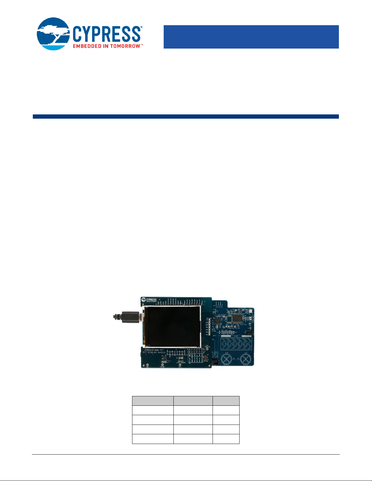
Related Hardware: CY8CKIT-062-BLE PSoC 6 BLE Pioneer Kit, CY8CKIT-028-TFT TFT Shield
Hardware Setup
1. Plug in the TFT display shield on to the Pioneer Board as Figure 1 shows.
Figure 1. Hardware Setup
2. Set the switches and jumpers on the Pioneer Board as shown in Table 1.
Table 1. Switch and Jumper Selection
Switch/Jumper
Position
Location
SW5
3.3 V
Front
SW6
PSoC 6 BLE
Back
SW7
V
DDD
/ KitProg2
Back
J8
Installed
Back
Page 2
PSoC 6 TFT Display Interface with EmWin Graphics Library
www.cypress.com Document Number: 002-23726 Rev. *B 2
Software Setup
Install the CY8CKIT-62-BLE PSoC 6 BLE Pioneer Kit software, which contains all the required software to evaluate this code
example. No additional software setup is required.
Operation
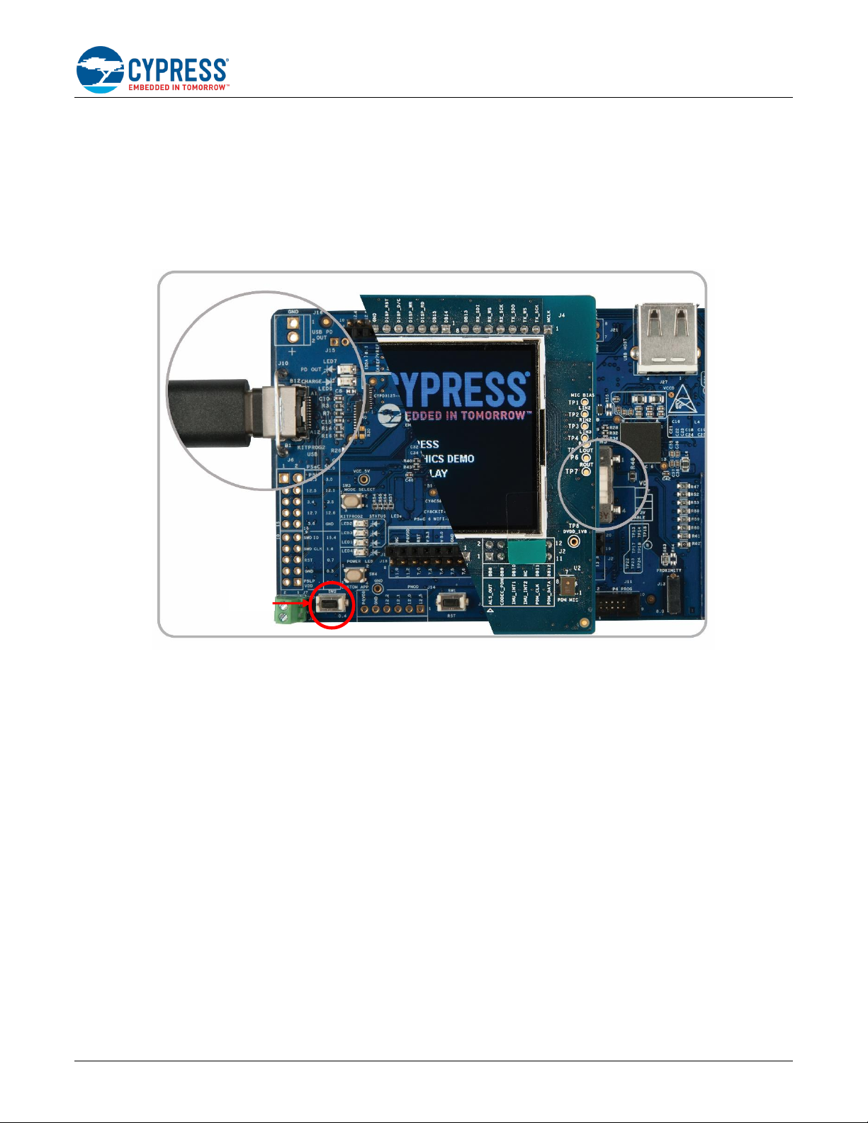
1. Connect the Pioneer Board to your PC using the provided USB cable through the USB connector (J10).
Figure 2. Connecting the USB Cable to the Pioneer Board
2. Program the Pioneer Board with the CE23726_EmWin_TFT_Display_ST7789 project. See the CY8CKIT-062-BLE kit guide
for details on how to program firmware into the device.
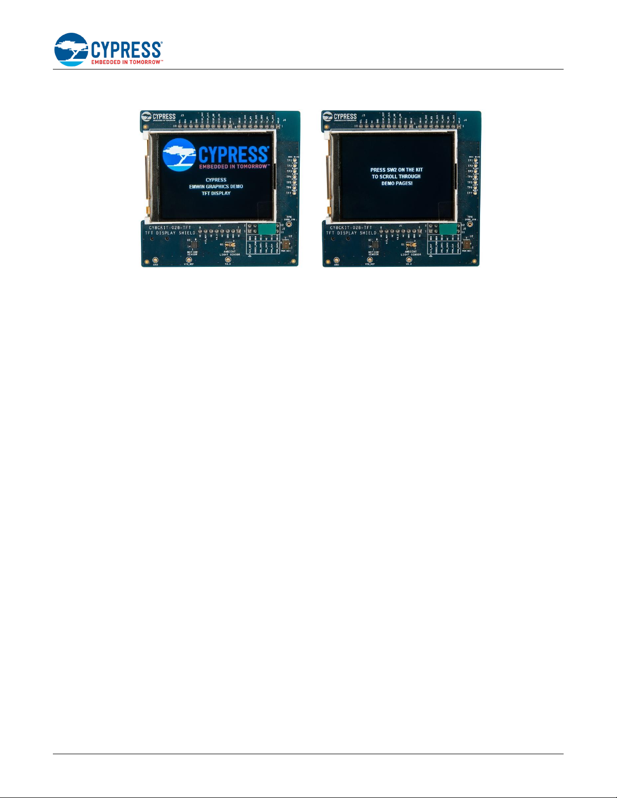
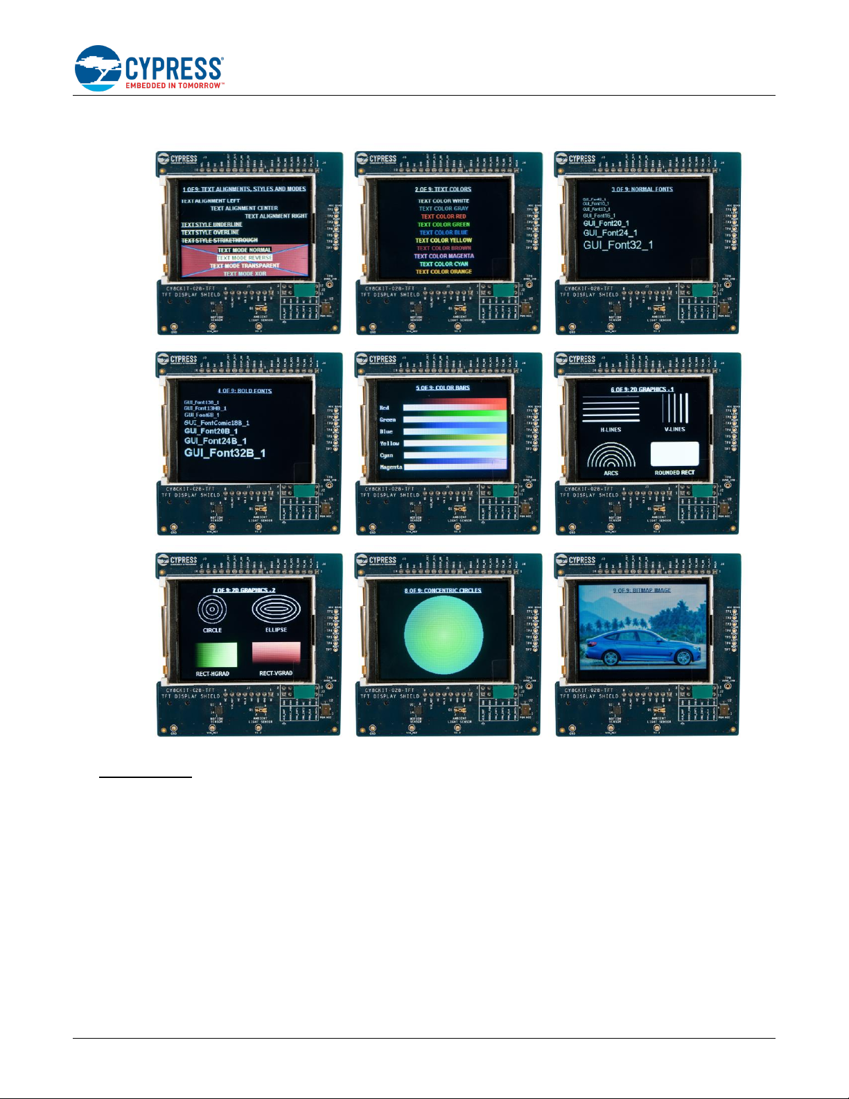
The TFT display shows the startup screen for three seconds, followed by a screen that displays instructions to press SW2
to scroll through various demo pages. Press SW2 to advance through the following pages that demonstrate various graphics
features in EmWin.
• Text alignments, styles, and modes
• Text colors
• Normal fonts of various sizes
• Bold fonts of various sizes
• Color bars
• 2D graphics with vertical lines, horizontal lines, arcs, and rectangles
• 2D graphics with concentric circles and ellipses, and rectangles with gradient fills
• Concentric circles
• Bitmap image
Figure 3 shows the startup and instructions screens. Figure 4 shows all the screens that are shown in sequence.
Page 3
PSoC 6 TFT Display Interface with EmWin Graphics Library
www.cypress.com Document Number: 002-23726 Rev. *B 3
Figure 3. Startup Screen and Instructions Screen
Page 4
PSoC 6 TFT Display Interface with EmWin Graphics Library
www.cypress.com Document Number: 002-23726 Rev. *B 4
Figure 4. Pages Shown in Sequence
Important Note:
When you build the project, you will see the following notification. Click OK.
Page 5

PSoC 6 TFT Display Interface with EmWin Graphics Library
www.cypress.com Document Number: 002-23726 Rev. *B 5
Figure 5. Build Messages
After this, a notification is displayed.
Figure 6. Updated Configuration Files
Deselect the file (it is deselected by default), and click Replace. If you select the file and click Replace, the configuration file in
the code example project will be replaced by the default configuration file.
Design and Implementation
This project uses a CY8CKIT-028-TFT TFT Display Shield together with the CY8CKIT-062-BLE Pioneer Board. The TFT shield
has a Newhaven 2.4″ 320×240 TFT display with a Sitronix ST7789 display controller and uses the 8080-Series Parallel Interface.
There are two important parts in this code example:
1. EmWin Graphics Library: The EmWin Graphics Library is implemented as a middleware in PDL and implements all
graphics functions. The library manages a display buffer and updates this display buffer with pixel data according to graphics
operations performed. The library also communicates with the display driver using the 8-bit parallel interface implemented
using the GraphicLCDIntf Component, and the LCD access routines defined in the LCDConf.c file.
2. Application Code: The application code calls the EmWin graphics APIs to perform various graphics functions.
Page 6

PSoC 6 TFT Display Interface with EmWin Graphics Library
www.cypress.com Document Number: 002-23726 Rev. *B 6
Include and Configure EmWin Graphics Library
1. In PSoC Creator, go to Project > Build Settings, and select Peripheral Driver Library. Under the Graphics > emWin
section, select the Core and LCD Driver options.
Figure 7. Build Settings
2. Select the nOSnTS option for Core because this project does not use RTOS or Touch support.
Figure 8. Core Option
3. Select “FlexColor” option for the “LCD Driver” parameter. This driver supports the ST7789 display controller.
Figure 9. Select LCD Driver Options
4. Click Generate Application.
Figure 10. Generate Application
Page 7

PSoC 6 TFT Display Interface with EmWin Graphics Library
www.cypress.com Document Number: 002-23726 Rev. *B 7
PSoC Creator generates the configuration files for EmWin under the Shared Files folder as shown in Figure 11.
Figure 11. Configuration Files Generated
5. Open the LCDConf.c file and configure the X and Y sizes of the display, the color palette, and display driver.
Figure 12. Setting the X and Y Values and Color Conversion
The ST7789S controller has a resolution of 240x320 pixels.
This controller supports various color palettes. This project uses the 16 bits per pixel RGB 5-6-5 color palette (5 bits R,
6 bits G, 6 bits G). Per the EmWin user guide Section 15.6 “Fixed Palette Modes”, this color palette is named
GUICC_M565.
The ST7789S controller is supported by the FlexColor driver; therefore, set the driver to GUI_FLEXCOLOR.
6. In the LCDConf.c file, write code in the _InitController function to initialize the hardware interface and display
controller. The EmWin library calls this function during the initialization stage. Some code snippets from this function
are shown below.
Page 8

PSoC 6 TFT Display Interface with EmWin Graphics Library
www.cypress.com Document Number: 002-23726 Rev. *B 8
/* Start the parallel interface */
GraphicLCDIntf_1_Start();
/* Reset - High, Low (reset), High */
Cy_GPIO_Set(LCD_RESET_N_0_PORT, LCD_RESET_N_0_NUM);
GUI_Delay(20);
Cy_GPIO_Clr(LCD_RESET_N_0_PORT, LCD_RESET_N_0_NUM);
GUI_Delay(100);
Cy_GPIO_Set(LCD_RESET_N_0_PORT, LCD_RESET_N_0_NUM);
GUI_Delay(100);
….
GraphicLCDIntf_1_Write8_A0(0x28);
GraphicLCDIntf_1_Write8_A0(0x11); //Exit Sleep mode
GUI_Delay(100);
GraphicLCDIntf_1_Write8_A0(0x36);
GraphicLCDIntf_1_Write8_A1(0xA0);//MADCTL: memory data access control
GraphicLCDIntf_1_Write8_A0(0x3A);
GraphicLCDIntf_1_Write8_A1(0x65);//COLMOD: Interface Pixel format
….
If a different display controller is used, this function must be modified to send the appropriate command and data bytes
as defined in the controller data sheet.
7. In the LCDConf.c file, the LCD_X_Config function configures various parameters required by the driver. Some
important parts of this function are shown below.
The GUI_DEVICE_CreatAndLink function sets the display driver and color palette.
GUI_DEVICE * pDevice;
pDevice = GUI_DEVICE_CreateAndLink(DISPLAY_DRIVER, COLOR_CONVERSION, 0, 0);
The configuration structure is updated with the display orientation; the GUIDRV_FlexColor_Config function sets up
the display driver. The ST7789S controller has a resolution of 240x320. However, the display used in the TFT shield
has a resolution of 320x240. Because of this swapping of X and Y resolutions, the orientation is set to swap X and Y
axes and mirror the Y axis.
CONFIG_FLEXCOLOR Config = {0};
Config.Orientation = GUI_MIRROR_Y | GUI_SWAP_XY;
GUIDRV_FlexColor_Config(pDevice, &Config);
The PortAPI structure sets the pointers to the APIs that perform read and write through the GraphicLCDIntf parallel
interface. The GUIDRV_FlexColor_SetFunc function is called to configure the Port APIs, specific display controller,
and interface.
GUI_PORT_API PortAPI = {0};
PortAPI.pfWrite8_A0 = GraphicLCDIntf_1_Write8_A0;
PortAPI.pfWrite8_A1 = GraphicLCDIntf_1_Write8_A1;
PortAPI.pfWriteM8_A1 = GraphicLCDIntf_1_WriteM8_A1;
PortAPI.pfRead8_A1 = GraphicLCDIntf_1_Read8_A1;
PortAPI.pfReadM8_A1 = GraphicLCDIntf_1_ReadM8_A1;
GUIDRV_FlexColor_SetFunc(pDevice, &PortAPI, GUIDRV_FLEXCOLOR_F66709, GUIDRV_FLEXCOLOR_M16C0B8);
See Section 33.7.4 “GUIDRV_FlexColor” in the EmWin user guide for details.
8. Open the GUIConf.c file. This file manages the RAM allocation for the EmWin library. The value of the macro
GUI_NUMBYTES macro must be set according to the approximate memory requirement based on EmWin library
features used by the application. This will depend on the various options enabled in the GUIConf.h file. See Section
37.2, “Memory Requirements” in the EmWin user guide for details on the memory usage for various features. For this
code example, the memory size has been set to an arbitrary 0x1000 bytes. You can set this to a smaller value based
on the features used in your application.
9. The GUI_X.c file has timing functions used by the EmWin library. The content of this file varies based on the OS
support selected. No modifications are required in this file for this code example.
Page 9

PSoC 6 TFT Display Interface with EmWin Graphics Library
www.cypress.com Document Number: 002-23726 Rev. *B 9
Main Application:
Hardware:
Figure 13 shows the schematics of the main application.
Figure 13. Schematic
The GraphicLCDIntf Component is used to implement the 8-bit parallel interface to communicate with the display controller. The
PortAPI structure of the EmWin driver is updated with the APIs from this Component.
SW2 is a digital input that is connected to SW2 on the CY8CKIT-062-BLE kit. This pin is configured as Resistive Pull Up. SW2
is connected to a Status Register to read the switch status. A 100-Hz clock is connected to the clock input of the Status Register
which also provides a 10-ms debounce.
Figure 14 shows the port pin configuration for GraphicLCDIntf and SW2.
Figure 14. Port Pin Configuration for GraphicLCDIntf and SW2
Firmware:
The main application is implemented in the main_cm4.c file. The following functions are performed in main:
1. Initializing the EmWin graphics engine
2. Displaying the startup screen
Page 10

PSoC 6 TFT Display Interface with EmWin Graphics Library
www.cypress.com Document Number: 002-23726 Rev. *B 10
3. Displaying the instructions screen that prompts the user to press SW2 to scroll through various display pages
4. Displaying the following pages in an infinite loop. After displaying each page, waiting for a press and release event of
SW2.
a. Text alignments, styles, and modes
b. Text colors
c. Normal fonts
d. Bold fonts
e. Color bars
f. 2D graphics with horizontal lines, vertical lines, arcs, and filled rectangle
g. 2D graphics with concentric circles, concentric ellipses, rectangles with horizontal, and vertical gradient fills
h. Concentric circles with color gradient
i. Bitmap image with overlaid text
Components
Component
Instance Name
Function
GraphicLCDIntf
GraphicLCDIntf_1
8-bit parallel interface for the LCD driver
Digital Output Pin
LCD_RESET_N
This GPIO is used to reset the display controller.
Digital Input Pin
SW2
This pin is connected to an external switch SW2 on the CY8CKIT-062-BLE board.
Status Register
Status_SW2
This status register is used to read SW2 status.
See the PSoC Creator project for more details on PSoC Component configurations and design-wide resource settings.
Related Documents
Application Notes
AN210781 – Getting Started with PSoC 6 MCU
with Bluetooth Low Energy (BLE) Connectivity
Describes PSoC 6 MCU with BLE Connectivity devices and how to build your first PSoC
Creator project
AN215656 – PSoC 6 MCU: Dual-CPU system
Design
Describes the dual-CPU architecture in PSoC 6 MCU, and shows how to build a simple
dual-CPU design
AN219434 – Importing PSoC Creator Code
into an IDE for a PSoC 6 MCU Project
Describes how to import the code generated by PSoC Creator into your preferred IDE
PSoC Creator Component Datasheets
Pins
Supports connection of hardware resources to physical pins
Clock
Supports local clock generation
Status Register
Can be used to read the state of digital signals
Graphic LCD Interface
Implements 8 or 16 bit i8080 parallel interface
Device Documentation
PSoC 6 MCU: PSoC 63 with BLE Datasheet
PSoC 6 MCU: PSoC 63 with BLE Architecture Technical Reference Manual
Development Kit Documentation
CY8CKIT-062-BLE PSoC 6 BLE Pioneer Kit
Training Videos
PSoC 6 101: Lesson 1-4 FreeRTOS
Page 11

PSoC 6 TFT Display Interface with EmWin Graphics Library
www.cypress.com Document Number: 002-23726 Rev. *B 11
Document History
Document Title: CE223726 – PSoC 6 TFT Display Interface with EmWin Graphics Library
Document Number: 002-23726
Revision
ECN
Orig. of
Change
Submission
Date
Description of Change
**
6299269
GRAA
09/18/2018
New code example
*A
6393764
SRDS
11/26/2018
Updated the TFT display model details.
*B
6509596
SRDS
03/15/2019
Updated the TFT display link.
Page 12

PSoC 6 TFT Display Interface with EmWin Graphics Library
www.cypress.com Document Number: 002-23726 Rev. *B 12
Worldwide Sales and Design Support
Cypress maintains a worldwide network of offices, solution centers, manufacturer’s representatives, and distributors. To find the
office closest to you, visit us at Cypress Locations.
Products
Arm® Cortex® Microcontrollers
cypress.com/arm
Automotive
cypress.com/automotive
Clocks & Buffers
cypress.com/clocks
Interface
cypress.com/interface
Internet of Things
cypress.com/iot
Memory
cypress.com/memory
Microcontrollers
cypress.com/mcu
PSoC
cypress.com/psoc
Power Management ICs
cypress.com/pmic
Touch Sensing
cypress.com/touch
USB Controllers
cypress.com/usb
Wireless Connectivity
cypress.com/wireless
PSoC® Solutions
PSoC 1 | PSoC 3 | PSoC 4 | PSoC 5LP | PSoC 6 MCU
Cypress Developer Community
Community | Code Examples | Projects | Videos | Blogs
| Training | Components
Technical Support
cypress.com/support
All other trademarks or registered trademarks referenced herein are the property of their respective owners.
Cypress Semiconductor
198 Champion Court
San Jose, CA 95134-1709
© Cypress Semiconductor Corporation, 2018-2019. This document is the property of Cypress Semiconductor Corporation and its subsidiaries (“Cypress”). This
document, including any software or firmware included or referenced in this document (“Software”), is owned by Cypress under the intellectual property laws and
treaties of the United States and other countries worldwide. Cypress reserves all rights under such laws and treaties and does not, except as specifically stated in
this paragraph, grant any license under its patents, copyrights, trademarks, or other intellectual property rights. If the Software is not accompanied by a license
agreement and you do not otherwise have a written agreement with Cypress governing the use of the Software, then Cypress hereby grants you a personal, nonexclusive, nontransferable license (without the right to sublicense) (1) under its copyright rights in the Software (a) for Software provided in source code form, to
modify and reproduce the Software solely for use with Cypress hardware products, only internally within your organization, and (b) to distribute the Software in binary
code form externally to end users (either directly or indirectly through resellers and distributors), solely for use on Cypress hardware product units, and (2) under
those claims of Cypress’s patents that are infringed by the Software (as provided by Cypress, unmodified) to make, use, distribute, and import the Software solely
for use with Cypress hardware products. Any other use, reproduction, modification, translation, or compilation of the Software is prohibited.
TO THE EXTENT PERMITTED BY APPLICABLE LAW, CYPRESS MAKES NO WARRANTY OF ANY KIND, EXPRESS OR IMPLIED, WITH REGARD TO THIS
DOCUMENT OR ANY SOFTWARE OR ACCOMPANYING HARDWARE, INCLUDING, BUT NOT LIMITED TO, THE IMPLIED WARRANTIES OF
MERCHANTABILITY AND FITNESS FOR A PARTICULAR PURPOSE. No computing device can be absolutely secure. Therefore, despite security measures
implemented in Cypress hardware or software products, Cypress shall have no liability arising out of any security breach, such as unauthorized access to or use of
a Cypress product. CYPRESS DOES NOT REPRESENT, WARRANT, OR GUARANTEE THAT CYPRESS PRODUCTS, OR SYSTEMS CREATED USING
CYPRESS PRODUCTS, WILL BE FREE FROM CORRUPTION, ATTACK, VIRUSES, INTERFERENCE, HACKING, DATA LOSS OR THEFT, OR OTHER
SECURITY INTRUSION (collectively, “Security Breach”). Cypress disclaims any liability relating to any Security Breach, and you shall and hereby do release
Cypress from any claim, damage, or other liability arising from any Security Breach. In addition, the products described in these materials may contain design
defects or errors known as errata which may cause the product to deviate from published specifications. To the extent permitted by applicable law, Cypress reserves
the right to make changes to this document without further notice. Cypress does not assume any liability arising out of the application or use of any product or circuit
described in this document. Any information provided in this document, including any sample design information or programming code, is provided only for reference
purposes. It is the responsibility of the user of this document to properly design, program, and test the functionality and safety of any application made of this
information and any resulting product. “High-Risk Device” means any device or system whose failure could cause personal injury, death, or property damage.
Examples of High-Risk Devices are weapons, nuclear installations, surgical implants, and other medical devices. “Critical Component” means any component of a
High-Risk Device whose failure to perform can be reasonably expected to cause, directly or indirectly, the failure of the High-Risk Device, or to affect its safety or
effectiveness. Cypress is not liable, in whole or in part, and you shall and hereby do release Cypress from any claim, damage, or other liability arising from any use
of a Cypress product as a Critical Component in a High-Risk Device. You shall indemnify and hold Cypress, its directors, officers, employees, agents, affiliates,
distributors, and assigns harmless from and against all claims, costs, damages, and expenses, arising out of any claim, including claims for product liability, personal
injury or death, or property damage arising from any use of a Cypress product as a Critical Component in a High-Risk Device. Cypress products are not intended
or authorized for use as a Critical Component in any High-Risk Device except to the limited extent that (i) Cypress’s published data sheet for the product explicitly
states Cypress has qualified the product for use in a specific High-Risk Device, or (ii) Cypress has given you advance written authorization to use the product as a
Critical Component in the specific High-Risk Device and you have signed a separate indemnification agreement.
Cypress, the Cypress logo, Spansion, the Spansion logo, and combinations thereof, WICED, PSoC, CapSense, EZ-USB, F-RAM, and Traveo are trademarks or
registered trademarks of Cypress in the United States and other countries. For a more complete list of Cypress trademarks, visit cypress.com. Other names and
brands may be claimed as property of their respective owners.
 Loading...