

Page 1

CDPS-UC4H4CVES
4 by 4 HDMI 4K UHD over CAT5e/6/7Matrix
with
Micro Control
System
O
Oppeerraattiioonn
M
Maannuuaall
Page 2

DISCLAIMERS
The information in this manual has been carefully checked and is
believed to be accurate. Cypress Technology assumes no
responsibility for any infringements of patents or other rights of third
parties which may result from its use.
Cypress Technology assumes no responsibility for any inaccuracies
that may be contained in this document. Cypress also makes no
commitment to update or to keep current the information contained
in this document.
Cypress Technology reserves the right to make improvements to this
document and/or product at any time and without notice.
COPYRIGHT NOTICE
No part of this document may be reproduced, transmitted,
transcribed, stored in a retrieval system, or any of its part translated
into any language or computer file, in any form or by any means—
electronic, mechanical, magnetic, optical, chemical, manual, or
otherwise—without express written permission and consent from
Cypress Technology.
© Copyright 2011 by Cypress Technology.
All Rights Reserved.
Version 1.1 August 2011
TRADEMARK ACKNOWLEDGMENTS
All products or service names mentioned in this document may be
trademarks of the companies with which they are associated.
3
Page 3

SAFETY PRECAUTIONS
Please read all instructions before attempting to unpack, install or
operate this equipment and before connecting the power supply.
Please keep the following in mind as you unpack and install this
equipment:
• Always follow basic safety precautions to reduce the risk of fire,
electrical shock and injury to persons.
• To prevent fire or shock hazard, do not expose the unit to rain,
moisture or install this product near water.
• Never spill liquid of any kind on or into this product.
• Never push an object of any kind into this product through any
openings or empty slots in the unit, as you may damage parts
inside the unit.
• Do not attach the power supply cabling to building surfaces.
• Use only the supplied power supply unit (PSU). Do not use the PSU
if it is damaged.
• Do not allow anything to rest on the power cabling or allow any
weight to be placed upon it or any person walk on it.
• To protect the unit from overheating, do not block any vents or
openings in the unit housing that provide ventilation and allow for
sufficient space for air to circulate around the unit.
REVISION HISTORY
VERSION NO. DATE (DD/MM/YY) SUMMARY OF CHANGE
VR0 24/09/15 Preliminary Release
VR1 17/02/16 Release RS-232 Command case-
insensitive
4
Page 4

CONTENTS
1. Introduction............................................ 6
2. Applications ........................................... 6
3. Package Contents ................................ 6
4. System Requirements............................ 7
5. Features
.................................................. 7
6. Operation Controls and Functions ....... 8
6.1 Front Panel ........................................
8
6.2 Rear Panel.........................................
9
6.3 Remote Control..............................
11
6.4 IR Cable Pin Assignments ..............
12
6.5 RS-232 Protocols .............................
13
6.6 RS-232 and Telnet Commands .....
13
6.7 OLED Menu .....................................
27
6.8 IP Searching Application ..
.........
...
30
6.9 Telnet Control ..............................31
6.10 WebGUI Control ..... ....................
34
6.10.1 Routing Settings..................
34
6.10.2 HDBaseT Info.......................
35
6.10.3 HDBaseT Settings ................
35
6.10.4 EDID Settings.......................
36
6.10.5 Macro Settings ...................
36
6.10.6 Command
Creation and
Settings.....
39
6.10.7 Trigger Settings ...................
42
6.10.8 UART Settings ......................
42
6.10.9 Network Settings ................
43
6.10.10 System Settings.................
43
7.
Connection Diagram ........................ 44
8. Specifications ..................................... 46
8.1 Technical Specifications ...............
46
8.2 Supported Resolutions ...................
47
5
Page 5

1. INTRODUCTION
This 4K2K 4 x 4 HDMI over CAT5e/6/7 Matrix with fast switch and
control system allows 4 HDMI signal sources to be routed to 4
HDBaseT™ outputs over a single CAT5e/6/7 cable up to 100 m for
each output. The Control System functions provide not only direct
but also indirect control interfaces for all your connected devices.
Supporting traditional direct control systems like IR, Relay and DC
trigger and indirect control systems like IR Learning, RS-232, Telnet/
WebGUI controls, it allows user with PC or APP based control systems
great flexibilities in controlling devices. The operation of the system
can be easily managed through
WebGUI
on PC/Laptop or APP on
mobile devices, on-panel buttons, IR remote, RS-232, Telnet
or Ethernet protocols.
2. APPLICATIONS
• Entertainment Room / Home Theater Display and System Controls
• Show Room / Demo Room Display and System Controls
• Lecture Room/Hall Presentation Display and System Control
• Public Commercial Display and System Control
• Information Board Display and System Control
3. PACKAGE CONTENTS
• 1×4 by 4 HDMI 4K UHD over CAT5e/6/7 Matrix
• 1×Remote Control with Battery
• 1×IR
3.5 mm standard
Extender
• 1×IR
3.5 mm
Blaster
• 1×IR
3.5 mm
Learner Extender
(red dot)
• 4×Terminal Blocks
• 1×Set of Rack Ears
• 1×24 V/2.7 A DC Power Adaptor
• 1× Power Cord
• 1×Operation Manual
6
Page 6

4. SYSTEM REQUIREMENTS
Input source equipment such as Blu-ray/DVD/PS3 player or Set-Top-Box
and output HDBaseT Receivers to TV/Display and or audio amplifier
with connection cables.
Control system input devices such as security door/windows, lights,
curtain, or devices like players, sound systems, or any other
controllable device with IR/RS-232 or net service link design with PC/
smart phone to send commands to control the whole system.
5. FEATURES
• HDMI with 3D & 4K2K supported, HDCP and DVI compliant
• Supports HDTV resolutions up to 4K2K (3840x2160@24/25/30,
3840x2160@50/60_YUV420 & 4096x2160 @24/25/30, 4096x2160
@50/60_YUV420)
• Supports individual EDID or common EDID
• Supports pass through of audio formats: LPCM 2/5.1/7.1CH, Dolby
Digital 2/5.1CH, DTS 2/5.1CH, Dolby Digital Plus, Dolby TrueHD, Dolby
Atmos and DTS-HD Master Audio
• HDCP 1.4 for 4 HDMI inputs and 4 HDBaseT outputs with HDBaseT
5PlayTM features
• Input port HDCP support Standard and Apple mode. The Apple
mode selection to guarantees the use of Apple devices
• Compliant with DVI source (Not support Deep color and Color
space YCbCr 422/444)
• Supports IR Learning function: Allows IR signals to be stored in the
system and used for control
external devices
• Supports eight Terminal Block inputs with voltage of 5~15V
• Supports 1 IR Learning port, 8 IR outputs, 8 control inputs, 8 Relay
outputs, 2 COM ports, and 4 Ethernet ports
• Supports Baud rates up to 115,200bps
• Supports 10/100Mbps Ethernet network connection
7
Page 7

6. OPERATION CONTROLS AND FUNCTION
6.1 Front Panel
8 9 111 13
1 POWER: Press this button to turn ON the device and the LED
will illuminated.
2 IR WINDOW: This IR Receiver receives the remote control signal
only from the IR Control included in the package.
3 OUT A~D: Press OUT button once a time along with an IN
buttons to select an input source for an output display. i.e. OUT
A→ IN1→TAKE or OUT B→ IN4→TAKE.
4 IN 1~4: Press IN button to select input from 4 sources.
5 TAKE: Press this button to confirm the selection of an IN and
an OUT button. If this button is not pressed the selection will not
execute.
6 CANCEL: Press this button to cancel the selection.
7 MENU: Press to enter into the menu.
8 ENTER: Press to confirm selection.
9 PLUS (+)/MINUS (-): Press to select page up and down under
menu select.
10 ALL: Press to select an input into all output.
11 PRESET: Press this button, the OLED will show preset selection
then select from IN 1~4 and press “TAKE” to confirm the
selection or press “CANCEL” to cancel the selection.
12 LOCK: Press to lock on all button functions on the front panel.
Press for 3 seconds to relieve the lock function.
13 MODE: Press this button to switch in between the TAKE
mode/Real Time mode. OLED will show current selection on the
top right side, press TAKE to confirm the switch.
14 OLED: Display input and output selection and menu
selection.
8
Page 8

6.2 Rear Panel
1 IRL: Connect with IR Receiver, provided with the unit, for IR signal
learning. Send the IR signal to be learnt direct towards the Receiver and
use WebGUI to store the IR code. For details please refers to section
6.10.4
Note: Although both IR Extender and IR Learner may look
the same, they are however different. IR Extender is
designed with more reddish color whereas IR Learner has
a brownish color and a “
red dot”
on the back. Please pay
extra attention in connecting and using it.
2 EXT OUT 1~8: Connect with IR Blaster for IR signal
transmitting.
3 TRIGGER IN 1~8: Connect with external event device
signals such window security alarm, door switch, etc…
The trigger IN 1÷8 ports are isolated current loop with no reference to
ground. The upper leads are positive and lower leads are negative
In the example below drawn, the external sensor permits the current flow
from positive to negative terminal. The user must limit the current with an
external resistor (typically 1Kohm). The external sensor can be a “dry
contact” or an “open collector” device. The threshold is about 6 mA
9
Page 9

Warning:
The trigger event causes the execution of the Macro
with the same number
For example, the event on trigger N°1, if enabled,
causes the execution of the Macro N°1
It’s possible to set by GUI the mode of the event
(rise, falling, change).
When the input trigger is disabled
the event on the input trigger has no effect.
4 RELAY OUT 1~8: N° 8 dry contacts are provided to perform the
necessary external functions.
5 COM 1/2: Connect to peripherals that present RS-232 for control
purpose. Use also TELNET client to send command directly to the
peripherals. Set the connected port to 7501 for COM 1 and 7502 for
COM2
6
LAN 1~4: Connect with devices that obtain RJ-45 input for control
and data transmitting purpose within the connected LAN system.
7 HDMI IN 1~4 and IR OUT: Connect the source equipment such as
Blu-ray/DVD/PS3 players and Set-Top-Box. IR OUTs must be
connected with IR Blaster for IR signal transmission from IR receivers
connected to the HDBaseT Receivers/Zone.
8 CAT5e/6 OUT A~D and IR IN 1~4: Connect to HDBaseT Receivers by
CAT6 cable. IR IN must be connected to IR Receivers for IR signal
transmission from the designated input HDMI ports
to zones A-D
.
9 SERVICE: This slot is reserved for firmware update use only.
10 CONTROL: Connect from PC/Laptop with active internet service
or Ethernet switch/Hub for WebGUI control and or data transmitting.
11 RS-232: Connect from PC/Laptop for RS-232 command sending to
control the device.
12 ALL IR OUT: Connect with IR Blaster for IR signal transmission with
signal received from the all zone. Place the IR Blaster in direct line-
of-sight of the equipment to be controlled.
10
Page 10

13 ALL IR IN: Connect with IR Receiver for IR signal transmission to all
the zone. Ensure that Remote Control being used is within the direct
line-of-sight of the IR Receiver.
14 DC 24V: Connect the adaptor with power cord included in the
package and connect to AC wall outlet for power supply.
6.3 Remote Control
1. POWER: Press this button to switch
the system ON/OFF.
2. OUT A÷D: Press one button to select OUT;
then press IN 1÷4 to select the input to be
routed
3. IN 1÷4: Press one button to select the
input to be routed to the output
previously selected
4. ALL: Press this button to select all outputs
5. TAKE: Press this button to confirm the
previous selection OUT / IN. If not pressed,
the selection is not executed
6. CANCEL: Press this button to cancel the selection.
7. PRESET: Press this button, the OLED will show preset selection. Select
IN 1~4 and press “TAKE” to confirm or “CANCEL” to clear.
8. LOCK: Press to lock on all button functions on the front panel. Press
again to relieve the lock function.
9. MENU: Press to enter into the menu.
10. ENTER: Press to enter into the menu selections.
PLUS (+)/MINUS (-): Press to select the page of the Menu up and down
MODE Press to switch between TAKE mode and Real Time mode
(OUT IN or IN OUT)
11
Page 11

6.4 IR Cable Pin Assignments
IR Blaster
1
Power
2
IR
Signal
3
NC
IR Extender
IR Learner
(Red dot)
1
IR Signal
2
Power
3
Grounding
1
IR Signal
2
Power
3
Grounding
Note: Due to both IR Extender and IR Learner cables are with similar
outlook, a part no. "CBL-IR10C3SA200A sticker has been placed
to differentiate the difference on IR Learner. IR Learner also
presents a “Red Dot” on its back
12
Page 12
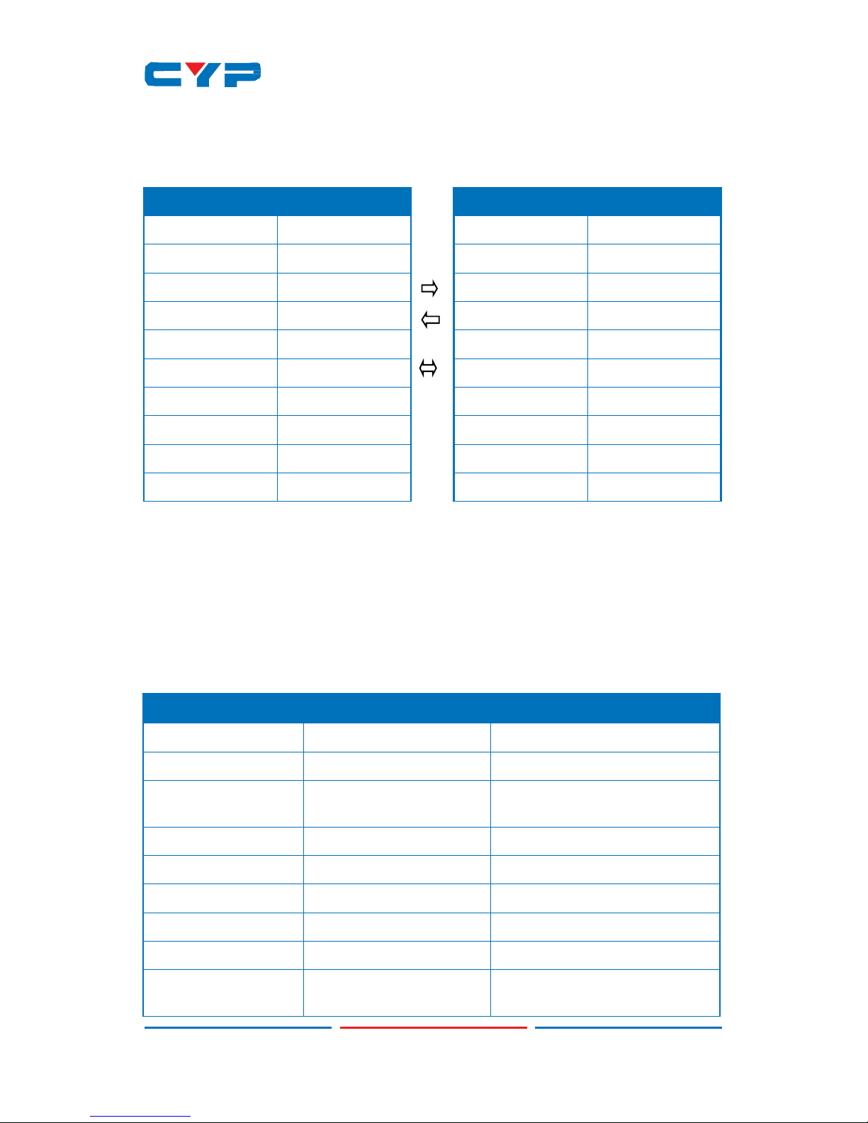
MATRIX
Pin
Assignment
1
NC
2
TXD
3
RXD
4
NC
5
GND
6
NC
7
NC
8
NC
9
NC
CONTROL DEVICE (Host)
Pin
Assignment
1
NC
2
RXD
3
TXD
4
NC
5
GND
6
NC
7
NC
8
NC
9
NC
6.5 RS-232 Protocols
Use an RS232 with Sub-D 9 pin F/M straight cable
Baud Rate: 115200 bps
Data bit: 8 bits
Parity: None
Flow Control: None
Stop Bit: 1
6.6 RS-232 and Telnet Commands
COMMAND DESCRIPTION PARAMETER
P0 Power Off (Standby) None
P1 Power On None
IPCONFIG Display The Current IP
Configure
None
SIPADDR X.X.X.X Set Ethernet IP Address X=0~255
SNETMASK X.X.X.X Set Ethernet Net Mask X=0~255
SGATEWAY X.X.X.X Set Ethernet Gateway X=0~255
HTTPPORT N1 Set Http Port Number N1=10~65535
TELNETPORT N1 Set Telnet Port Number N1=10~65535
RSTIP IP Configuration Set To
<DHCP>
None
13
Page 13

COMMAND DESCRIPTION PARAMETER
A N1 Select input N to output A N1=1~4
B N1 Select input N to output B N1=1~4
C N1 Select input N to output C N1=1~4
D N1 Select input N to output D N1=1~4
I N1
Select input N to all
output
N1=1~4
EDIDMODE Show EDID Mode None
EDIDMODE N1 Set EDID Mode N1=0 (Appoint), 1(All)
EDIDALL Show EDID Mode
Source for All
None
EDIDALL N1
Set EDID Mode Source
for All (See Note 1)
N1=0~9* (ref. OLED EDID ALL)
EDIDIN Show Input EDID Source None
EDIDIN N1
Show Input N1 EDID
Source
N1=1~4
EDIDIN N1 N2
Set Input N1 EDID
Source
N1=1~4
N2=0~9* (ref. OLED EDID ALL)
HDCPIN
Show All Input HDCP
Status
None
HDCPIN N1
Show Input N1 HDCP
Status
N1=1~4
HDCPIN N1 N2
Set Input N1 HDCP ON/
OFF
N1=1~4
N2=0 (OFF), 1 (ON)
PRESET Show All Preset
Configure
None
PRESET N1 Set Preset N1 Source to
Outputs
N1=1~4
PRESET N1 N2 Set Preset N1 Configure N1=1~4
N2=AXBXCXDX (X=1~4)
SOURCEDET Show All Input Signal None
SOURCEDET N1 Show Input N1 Signal N1=1~4
14
Page 14

COMMAND DESCRIPTION PARAMETER
SINKINFO Show All Output
Information
None
SINKINFO N1 Show Output N1
Information
N1=A~D
INNAME Show all Input name None
INNAME N1 Show Input N1 name N1=1~4
INNAME N1 N2 Set Input N1 Name N1=1~4
N2=ABCDEFGH…(Max
Length=8)
OUTNAME Show all Output name None
OUTNAME N1 Show Output N1 name N1=A~D
OUTNAME N1 N2 Set Output N1 name N1=A~D
N2=ABCDEFGH…(Max
Length=8)
MATRIXMODE
Show Matrix Current
mode
None
MATRIXMODE N1 Set Matrix mode N1 N1=0 (Real-time), 1 (Take)
VER
Show Device Firmware
version
None
REBOOT System Reboot None
HELP(?) Show Command list None
HELP(?) N
Show Command
description
N=Command name
UART_ROUTE UART Route Setting
Command
UART_ROUTE all
Allow UART Commands
to send out to all
HDBaseT output port
UART_ROUTE none
Block UART Commands
to send out to HDBaseT
output port
UART_ROUTE A~D
Send UART Commands
to the designated
output HDBaseT port
A~D
15
Page 15

COMMAND DESCRIPTION PARAMETER
IR_SELECT
IR Mask Addition/
Deletion command
IR_SELECT a[n] show Show IR port Status
(See Note 2)
(See 6.6.1 IR Signals
Flow)
a= to_zone[A~D]
to_source[1~4]
to_mcu[1]
to_notice[1]
n=A~D or 1~4
ex: IR_SELECT TO_ZONE[A]
SHOW
IR_SELECT ShowAll Show Current Setting
(See Note 3)
IR_SELECT a[n] add
b[n] c[n]…
Add IR command to
port
(See Note 4)
(See 6.6.2 IR
Command Function)
a= to_zone[A~D]
to_source[1~4]
to_mcu[1]
to_notice[1]
b c…=from_zone[A~D]
from_source[1~4]
from_mcu[1]
from_notice[1]
n=A~D or 1~4
ex: IR_SELECT TO_ZONE[A]
ADD FROM_NOTICE[1]
IR_SELECT a[n] del
b[n] c[n] …
Delete IR command
from port
(See Note 4)
(See 6.6.2 IR
Command Function)
a= to_zone[A~D]
to_source[1~4]
to_mcu[1]
to_notice[1]
b c…=from_zone[A~D]
from_source[1~4]
from_mcu[1]
from_notice[1]
n=A~D or 1~4
ex: IR_SELECT TO_MCU[1]
DEL FROM_ZONE[A]
16
Page 16

COMMAND DESCRIPTION PARAMETER
VALENS read a b c
d e…
Read and display
Valens Information
(See 6.6.3 HDBaseT
Command Function)
a= Local/Remote (HDBaseT
TX/RX)
b= HDBaseT output A~D
c d e...=FwID, FwDate,
FwType, HwType,
LnkSts, Cable, BERs,
AutoModeCap,
OperMode,
MemProtectSts,
RunningBankSts
VALENS write a b c
d
Write Valens Settings
(See 6.6.3 HDBaseT
Command Function)
a= Local/Remote (HDBaseT
TX/RX)
b= HDBaseT output A~D
c= MemProtection/
OperMode
d= On/Off (MemProtection)/
HdmiPassThrough,
EthernetFallBack, LPPF1,
LPPF2, LongReach,
HDBaseT, Auto
(OperMode)
VALENS FwUpd a b Update Valens Firmwa
re of Specified Chip
(See 6.6.3 HDBaseT
Command Function)
a= Local/Remote (HDBaseT
TX/RX)
b= HDBaseT output A~D
FADEFAULT All Configure Set to
Factory Default
ETH_FADEFAULT All Ethernet Configure
Set to Factory Default
CYP Set Ethernet MAC
address 48-Bit
c= nn-nn-nn-nn-nn-nn
d= nn=MAC Address
CMDTBL show Show All Command list Up to 128
CMDTBL show n Show Command list n=1~128
CMDTBL add n n1 Add Command n=1~128
n1= Command string up to
439 spaces
ex: CMDTBL ADD 1 SET A=1
1\x0d\x0a
CMDTBL del n Delete Command n=1~128
17
Page 17

COMMAND DESCRIPTION PARAMETER
CMDTBL name n
n1
Name Command n=1~8
n1=Up to 24 characters
including space
MACRO run n
Execute Macro
Command
n=1~8
COMCONF N1 N2
N3 N4 N5 N6
Set UART's Parameters
(See Note 5)
N1=COM/Zone
N2= Port/Zone no. 1~2/A~D
N3=Baud rate (4800~115200)
N4=Data bit (7~8)
N5=Parity (none/odd/even)
N6=Stop bit (1/2)
ex: COMCONF COM 2
115200 8 None 1
COMSEND n
n1 n2
Command Send to
Designated COM Port
(See Note 6)
n=COM/Zone
n1=Port/Zone no. 1~2/A~D
n2=Data
Note: Some command may
require to add a carriage
return (eg: \r or \x0D) in the
end to allow the system to
recognize it as an end of the
command.
IREMIT n
n1 n2 n3
Send IR Code to
Designated Output
Port (See Note 7)
n=IR/Zone/Source
n1=1~8/A~D/1~4
n2=0
n3=IR Code
IRLEARN N
IR Signal Learning and
Save into Data
N=IR code string
RELAY N N1
Relay Switch Setting
(See Note 8)
N= 1~8
N1= Open, Close, Toggle
ex: RELAY 1 Close
TRIGGER N N1 N2
Trigger Switch Setting
(See Note 9)
N= Status/Info/Active/Mode
N1= 1~8
N2=Active (Enable/Disable)/
Mode (Raising/Falling/
Change)
ex: TRIGGER Mode 5 Raising
18
Page 18

Warning
:
1.
Any commands will not be executed unless followed by a
carriage return. Commands are case-insensitive.
2. Commands with one asterisk (**) and two asterisks (***) please
refers to IR and HDBaseT Command Function below.
Note 1: For the EDIDALL N1 command, the EDID contents is:
0=Output A
1=Output B
2=Output C
3=Output D
4=8bit/2D/PCM/720p 5=8bit/2D/PCM/AC3/720p
6=8bit/2D/PCM/1080p 7=8bit/2D/PCM/AC3/1080p
8=8bit/2D/PCM/4K2K@60 9=8bit/2D/PCM/AC3/4K2K@60
Note 2: How to know the IR flow of the matrix
19
Page 19

Note 3: How to know the global status of the IR flows
Send the string as below: ir_select showall and the matrix replies with the
whole status.
Global status IR flow (10 rows)
20
Page 20

Note 4: How to enable or inhibit IR flows
Note 5: This command is useful to set the COM port to match the
specifications of the peripheral to be commanded by RS232.
As example, if the peripheral connected to COM1 is setted at 9600
baud, 8 bits, no parity, 1 stop bit, the following command must be sent to
the matrix:
COMCONF COM 1 9600 8 None 1\x0D where:
COMCONF command syntax
COM Referred to COM1 or COM2; else, Zone
1 Number of port COM on matrix (in this case
COM1)
9600
baud rate of the peripheral connected to
COM1
(in this case 9600)
8 data bits (in this case 8)
None Parity (in this case, no parity)
1 Number of stop bits (in this case 1)
\x0D CR (to close the command)
21
Page 21

Note 6: This command is useful to send a RS232 string to a peripheral
device connected to port COM1, COM2 or COM port of Zone A÷D.
As example, to send the simple command “1” followed by CR to the
peripheral connected to COM1, the string to be sent is:
COMSEND COM 1 1\
x0D
\x0D
where:
COMSEND command syntax
COM Referred to COM1 or COM2; else, Zone
1 Number of port COM on matrix (in this case
COM1)
1 ASCII character of the string sent through COM1
\
x0D
CR sent through COM1 on behalf of the
peripheral
\x0D CR in behalf of the matrix to close the
command string
Note 7: This command is useful to send by RS232 an IR string to an
external device by an IR emitter connected to one of the 8 IR port of the
matrix CDPS-UC4H4CVES, or to IR OUT jack of the HDBaseT Receiver
located in Zone A÷D, or to IR OUT jack of the matrix CDPS-UC4H4CVES.
In the GUI Control, go to the Command Settings section, open an IR
command and copy the string to be transmitted.
7.1 E.g., suppose that you want to send the IR “string” via IR port #5
Copy and p
aste the “string” in your RS232 command as it follows:
IREMIT IR 5 0 “string”\x0D where:
IREMIT command sysntax
IR
referred to the IR OUT of the matrix CDPS-UC4H4CVES
5
Number of port IR on matrix (in this case #5)
0 command syntax
“string” ASCII characters pasted
\x0D CR (to close the command)
22
Page 22

7.2 As second example, suppose that you want to send the IR “string” via
the IR Out jack of the HDBaseT receiver located in Zone A.
Paste the “string” in your RS232 command as it follows:
IREMIT zone A 0 “string”\x0D where:
IREMIT command sysntax
zone
referred to one of the four zones (A÷D)
A Number of Zone (in this case #A)
0 command syntax
“string” ASCII characters pasted
\x0D CR (to close the command)
Note 8: This command is suited to open, close or toggle one out of the
eight relays in the CDPS-UC4H4HFS
As example, to close the Relay #4 the string to be sent is:
RELAY 4 Close\x0D where:
Relay command syntax
4 Relay whose contact is connected to port #4
Close Command for Relay (may be also “open” or
“toggle”)
\x0D CR (to close the command)
Note 9: This is a complex command suited to know the status of a Trigger
Input, to set the characteristics of the Input trigger as Enable/Disable
and the mode, that can be Raising, Falling and Change.
a) To know the status of the trigger Input #1, send the string as it’s shown:
TRIGGER N1 N2\x0D where:
N1="Status"
N2=Port number.(1~8)
\x0D is CR
Sending command:
trigger status 1 CR
The matricx replies:
Port 1=High (or low)
23
Page 23

b) To know the status and Mode of the trigger Input #1, send the string
as it’s shown:
TRIGGER N1 N2\x0D where:
N1="Info"; N2=Port number.(1~8); \x0D is CR
Sending command:
trigger info 1
The matricx replies:
Port 1:=Status=High,
Active=Enable, Mode=Change
(it means that the status of trigger #1 is high and that it’s enabled on
change of the status)
c) To set the mode of the trigger Input #1 as “Falling”, send the string as
it’s shown:
TRIGGER N1 N2 N3\x0D where:
N1="Mode" ; N2=Port number.(1~8); N3="Raising" /"Falling"/ "Change";
\x0D is CR
Sending command:
trigger mode 1 falling
The matricx replies:
Port 1:=Status=High,
Active=Enable, Mode=Falling
(it means that it has setted the mode Falling on trigger #1)
d) To disable or enable the trigger Input #1, send the string as it’s shown:
TRIGGER N1 N2 N3\x0D where:
N1="Active"; N2=Port number.(1~8); N3="Enable"/"Disable"; \x0D is CR
Sending command:
trigger active 1 disable
The matricx replies:
Port 1:=Status=High,
Active=Disable, Mode=Falling
(it means that it has setted the trigger #1 disabled)
Sending command:
trigger active 1 enabled
The matricx replies:
Port 1:=Status=High,
Active=Enable, Mode=Falling
(it means that it has setted the trigger #1 enabled)
24
Page 24

6.6.1 IR Signals flow
The names used in the RS232 commands identify the various blocks of
the system in which the matrix is the core.
a) IR signal injected in the ALL IR IN “From_Notice” of the matrix is
transmitted to all blasters connected to IR OUT jack of the receivers
HDBase T located in the Zone 1÷4. The path must be enabled
b) IR signal generated by the IR receivers connected to the IR IN jack of
the receivers HDBaseT located in the Zone 1÷4, is repeated by the
blaster connected to ALL IR OUT “To_Notice” of the matrix. The path must
be enabled
c) The single IR signal generated by the IR receiver connected to the IR
IN1÷4 of the matrix “From_Source”, is repeated by the blaster connected
to IR OUT jack of the receivers HDBaseT located in the Zone A÷D and
follows the connection of the matrix. The path must be enabled
d) The single IR signal generated by the IR receiver connected to the IR
IN jack of the receivers HDBaseT located in the Zone A÷D, is repeated
by the blaster connected to IR OUT (HDMI IN 1÷4) of the matrix
“To_Source” and follows the connection of the matrix. The path must be
enabled
25
Page 25

6.6.2 IR Command Function
Parameter Allow Allow Not Allow Not Allow
to_zone from_notice from _mcu from_zone from_source
1
to_source from_notice from _mcu from_zone
2
from_source
to_mcu from_zone from_source from_notice from_mcu
to_notice from_zone from_source from_notice from_mcu
1. Though "from_source" is not allowed but actual hardware design
has built-in a router to transfer the IR signal from Source to zone
according to the matrix status.
2. Though "from_zone" is not allowed but actual hardware design
has built-in a route to transfer the IR signal from zone to source
according to the matrix status
6.6.3 HDBaseT Command Function
If
HDBaseT connection between local (the Matrix unit) and remote
(HDBaseT Receiver units) is not made, none of the command will be
executed.
- FwID: Firmware version information.
- FwDate: Firmware release date.
- FwType: Reveal current firmware if for TX end chip or Rx end chip.
- HwType: Reveal current chip hardware is Tx end or Rx end.
- LnkSts: HDBaseT link status.
- CableLen: Approximated cable length of current HDBaseT
connection on specified port.
- BERS: Approximated Bit Error Rate of current HDBaseT connection
on specified port.
- OperMode: Current chip connection mode on specified port.
- HDBaseT: Make HDBaseT connection between local and remote
chips.
- Auto: Automatic detection and connection making between
local and remote and chips.
- LongReach: Long reach mode between local and remote chips.
- HdmiPassThrough: HDMI pass through mode between local and
remote chips.
- EthernetFallBack: Fallback to normal Ethernet connection instead
of HDBaseT.
- LPPF1: Low Power Profile mode 1 between local and remote chips.
- LPPF2: Low Power Profile mode 1 between local and remote chips.
26
Page 26

6.7 OLED Menu
MAIN MENU SUB MENU DESCRIPTION DEFAULT
EDID Mode All
All Input port is
using same EDID.
In menu “EDID All”,
can select suitable
EDID.
All
Appoint
Each Input port can
select individual
EDID.
In menu “EDID
IN1~4” select
suitable EDID.
Exit
EDID All Sink A Copy Output A~D
display EDID
8/2D/
PCM/1080P
Sink B
Sink C
Sink D
8/2D/PCM/720P Standard EDID
settings.
Deep Color/2D3D/
Audio/Native
resolution.
8/2D/PCM/AC3/720P
8/2D/PCM/1080P
8/2D/PCM/AC3/1080P
8/2D/PCM/4K2K
8/2D/PCM/AC3/4K2K
Exit
EDID IN1 Same as EDID All. Select Input 1~4
EDID.
Same as EDID
All.
EDID IN2
EDID IN3
EDID IN4
Matrix
Preset
Preset 1 IN/OUT default
No.1~4.
A=1, B=2, C=3,
D=4
Preset 2
Preset 3
Preset 4
Exit
27
Page 27

MAIN MENU SUB MENU DESCRIPTION DEFAULT
HDCP Input IN1 Standard/ Apple
Set IN1~4 in
Standard/ Apple
mode.
Standard
IN2 Standard/ Apple
IN3 Standard/ Apple
IN4 Standard/ Apple
Exit
Network
Setup
IP Mode DHCP, Static Static
IP Setup Static IP. 192.168.1.50
Mask Setup Static Mask. 255.255.255.0
Gate Setup Static
Gateway
192.168.5.254
Do Re-Link
Re-Link After Setup
Network, the System
need to re-link.
Exit
Network
Status
Get IP
Network Status
DHCP, Static or Not
Linked.
Get Netmask
Get Gateway
System MAC
Exit
Source
Detection
IN1 On/Off
Detect IN1, IN2
source with/without
signal & HDCP.
IN2 On/Off
IN3 On/Off
Detect IN3, IN4
source with/without
signal & HDCP.
IN4 On/Off
Exit
Sink A Info HPD On/Off
Detect Sink
A
display with/without
Hot-Plugging&
R-sense.
Type Manuf./
Native/Video
Format/Audio
Format
RSEN On/Off
Exit
28
Page 28

MAIN MENU SUB MENU DESCRIPTION DEFAULT
Sink B Info Same as Sink A Info. Detect Sink B
display with/without
Hot-Plugging&
R-sense.
Same as Sink A
Info.
Sink C Info
Detect Sink C
display with/without
Hot-Plugging&
R-sense.
Sink D Info
Detect Sink D
display with/without
Hot-Plugging&
R-sense.
Firmware FW Version
Display Model
number & FW
Version.
Update FW Update.
Exit
Factory
Reset
Do Reset Do System Reset.
Exit
Exit
29
Page 29

6.8. IP Searching Application
Please download the software from www.cypress.com.tw with file
name CDPS V2.000 and save it in a directory where you may use it
later. Alternatively download the software “Browser for LAN
Modules” in the Available Software section of the page that show
the CDPS-UC4H4CVES in the web site Elpro
http://bit.ly/1UhkCSB
Connect the Control System with PC/Laptop through the Ethernet port
through an active network system and open the CDPS V2.000
application. Click on Find Devices on Network and a list of the devices
connected to the Control System will show up.
Then user may set the IP Address, SubNet Mask and Gateway of the
device to control it by Telnet and/or GUI
Then user m
ust
use the IP Address
set
to find the control device
through
Telnet, WebGUI or even RS-232/Hyper Terminal tools.
30
Page 30

6.9 Telnet Control
Under Mac iOS X, go to Go→Application→Utilities→Terminal.
To access the telnet control under MS windows 7, click ‘Start’ menu and
type “cmd” in the search field then press enter.
To access the telnet control under Windows 10, click “All Applications”,
then twice Windows PowerShell. See below
the
N°3 examples:
Mac iOS
Windows 7
Windows 10
31
Page 31

Once the command line interface (CLI) appears, type "Telnet", then the
IP address (in the case shown is 192.168.1.76), “23” and hit enter. (23 is
the port number of CDPS-UC4H4HFS)
This will bring into the unit which we wish to control. After the prompt
> appears, type "?” or “help" to list the available commands.
32
Page 32

Note: All the commands will be not executed unless followed by a
carriage return. Commands are case-insensitive
Warning:
To operate by Telnet under the Windows
systems, the functions “Client Telnet” and
“Client TFTP” must be enabled.
33
Page 33

6.
10 WebGUI Control
On a PC/Laptop that is connected to an active network system, open
a web browser and type device’s IP address (available from OLED
monitor) on the web address entry bar.
A security page will appear to ask for User and Password, please key
in “admin” for both and click Submit to enter.
Note: The Default IP setting is on Static with address at 192.168.1.50
The browser will display the device’s Routing, HDBaseT Info & Settings,
EDID, Macro, Command, Trigger, UART, Network and System Settings
Configuration pages for users to control.
6.10.1 Routing Settings
Click on 'Routing Settings' to select an input for output and the
selection will turn orange, naming inputs & outputs, preset and restore
video preset.
34
Page 34

6.10
.2 HDBaseT Info
Click on HDBaseT Info to read current CAT5e/6 output ports status.
6.10.3 HDBaseT Settings
Click on HDBaseT Settings to set both the CAT5e/6 output A~D and
the connected Receivers A~D’s HDBaseT mode, behavior and can
also update its firmware.
35
Page 35

6.10.4 EDID Settings
Click on EDID Settings to select EDID Mode and Set EDID Input
content.
6.10.5 Macro Settings
Macro 1~8 works aligned with Trigger IN 1~8. This means that when a
trigger signal is activated, the control system will execute the
Macro
with the same number.
Click on 'Macro Settings' to execute Macro. Click on the mark to
edit the command settings. Up to 16 command per each Macro can be
edited.
a) How to Add, cancel or modify the commands within a Macro
After clicking on the the mark, a mask appears: Command can be
set to control the internal System/SysCMD, RS-232 COM ports, IR and
Relays. It is suggested the delay time is >100ms among command
See the figure on the following page:
36
Page 36

Click on Add button to insert commands. Then click on the command to
be added
Command must be setted depending on the destination:
-SysCMD (internal the CDPS-UC4H4
CVES
, e.g. routing an Input to an Output)
-Telnet (external devices, e.g. towards a CDPS-CS4)
-COM
(COM1 or COM2 of CDPS-UC4H4H
CVES)
-IR
(IR1÷IR8 ports of CDPS-UC4H4H
CVES)
-Relay
(Relay #1÷ Relay #8 of the CDPS-UC4H4H
CVES)
The following page shows the setting for Telnet, COM, IR and Relay.
37
Page 37

Click on Save Change to confirm the settings.
Note 1: When a command is intended to an external Telnet address, it’s
necessary to set the Port Number as it follows:
23
Port number for
CDPS-CS4,
CDPS-
UC4H4HFS
, CDPW-K1/CDPW-K1S
7501
COM1 port number of CDPS-CS4
or CDPS-4H4HFS
7502
COM2 port number of CDPS-CS4
or CDPS-4H4HFS
Note 2: Delay paramenter is the delay before the following command is
executed. Standard delay is 100ms; for consecutive Telnet is 500 ms
Port 23: See Note 1 in end of page
Delay 100: See Note 2 in end of page
38
Page 38

6.10.6 Command Creation and Settings
The user can set up to 128 commands.
The “standard” commands can have up to 128 characters.
It’s possible to create “big” commands that have from 128 up to 512
characters. In this case, we can have 32 “big” commands and 96
“standard” commands.
To create a command, click on
the label “Command
settings”
Then click on “Edit”
a) How to create (and store) an IR command
Warning: First of all, be sure that the proper IR receiver (with the dot) is
connected to the “IRL” jack of the matrix CDPS-UC4H4
CVES
.
After click on “Edit” a mask appears:
Click on IR Learn and, within 5 seconds,
hit the IR receiver with the IR beam that
you want to store.
After the IR is learnt, in the mask is
visible the IR string.
Click on Save Change to store the
command. (Not visible here)
39
Page 39

a1) On the other hand, there is a second way to store the IR code.
You also can use the RS232 command "IRLEARN" to fetch the IR code;
then you can copy the IR code shown on the console screen and paste
it in the editing area Command (see above), and press "Save Change"
to save it.
a2) Or, third way, if you have an IR code that was fetched before, you
can do the same copy-and-paste to save the IR code in the editing
area Command (see above).
b) How to create a command RS232
After click on “Edit” a mask appears:
Type the desired
name of the
command (in this
case, “RS232 string)
Type the RS232
string.
E.g., if you want to
send the hex string:
31 0D, type
\x31\x0D
Then click on “Save
Change”, on the
rigth side (not visible
here)
Note: Some command may require to add a carriage return
(eg:\r or \x0D) in the end to allow the system to recognize it as
an end of the command.
40
Page 40

c) How to create a command to close, open or toggle a relay
After click on “Edit” a mask appears:
Type the desired name of the command (in this case, “Close Relay”)
Type the parameter of command extracted from the RS232 parameters;
in this case, “close”.
Please note that if we want to open the relay, the command must be
“open” and if we want to change status of the relay, the command
must be “toggle”
41
Page 41

6.10.7 Trigger Settings
Click on 'Trigger Settings' to view the current trigger status and edit
the trigger behavior. Default setting Status is on Low, Active is on
Enable and Mode is on Change, where Status represent the current
input connection signal status
; Active represent enabling or not the
trigger action and Mode represent the trigger setting of the input
signal. Under mode selection there are Raising, Falling and Change
where Raising represent the signal from low to high, falling represent
the signal from high to low and change represent both high and low
signals transition
.
6.10.8 UART Settings
Click on 'UART Settings' to set each COM port's Baud rate, Data bit, Parity
and Stop bit. Figures out of the selection range can be set under RS-232
or Telnet as well
.
42
Page 42

6.10.9 Network Settings
Click on Network Settings to set the device’s IP Mode. Once the change
is saved the system will reset the IP address on the device automatically
and user will need to re-enter the IP address to continue the WebGUI
function.
6.10.10 System Settings
Click on System Settings to set power to On/Standby. Matrix Mode is to
allow the device’s front panel I/O selection to be real time or must press
the take button to execute the selection. Download Current
Configuration is to save the current setting into your PC/Laptop and
Restore Configuration is to bring up a saved setting from your PC/
Laptop. Reset to Default and Reboot the Unit is to set the device back to
factory setting and restart the device again.
43
Page 43

8
60°
60
RX
7. CONNECTION DIAGRAM
Alarm
Sensor
Blind
Contr ol
Scree n
Contr ol
Lighti ng
Contr ol
Integrated 3rd Party Control
RS-
232 Connectio
IR
Blasters
1.5m
°
3m
3m
7m
IR Learner
IRL
EXTT OUT
COM 11
COM 22
LAN
11
2 3 4 5 6 7
IN
OUT
11 22 33 44
IR OUTT IIRR OUTT IIRR OUTT IIRR OUTT IIRR IN 11 IR IN 22 IR IN 33 IR IN 44
IR BLASTER
IR RECEIVER
HDMI IN 11
HDMI IN 22
HDMI IN 33
HDMI IN 44
CAT5e/6 OUTT AA CAT5e/6 OUTT BB CAT5e/6 OUTT CC CAT5e/6 OUTT DD
SERVICE CONTROL
HDMI Inputs & IR Extenders
HDMI
Out
LAN
RS-232 Out
Receiver
CAT5e/6 to HDMI with LAN/IR/R S232
Set-top Box
Satellite Receiver
DVD/Blu-ray Player DVD/Blu-ray Player Smart TV
44
Page 44

RX
RX
RX
RS-232 Controlled
Devices
ns
Games Console
Smart TV
PC/Laptop
Media Sever
LAN Connections
ALLL
RS232
IR OUT IRR IN DC
24V
Power Supply
RS-232
RS-232
Equipped
PC/Laptop
IR Blaster
IR Extender
LAN
Internet
Connected
Router
CAT5e/6/7 Cable Outputs
HDMI O ut
RS-23 2 Out
Receiver
LAN
CAT5e/6 to HDMI with L AN/IR/RS232
HDMI Out
RS-23 2 Out
Receiver
LAN
CAT5e/6 to HDMI with L AN/IR/RS232
HDMI
Out
RS-23 2 Out
Receiver
LAN
CAT5e/6 to HDMI with L AN/IR/RS232
Smart TV Smart TV Smart TV
45
Page 45

8. SPECIFICATIONS
8.1 Technical Specifications
Video Bandwidth 300 MHz/3 Gbps
Input Ports 4×HDMI, 1×RS-232, 1×Control, 5x IR IN,
2×COM port (D-Sub 9-pin), 4×LAN, 8×Input
(0~15V, 0~5/level low, 5~15/level high),
1×IR Learner, 1×USB (service)
Output Ports
4×CAT5e/6, 8×Relay Output, 8×IR, 5×IR
OUT
Supported Resolutions 480i~1080p@24/50/60, 4K2K@24/25/30,
4K2K@50/60 (YUV420) & VGA~WUXGA (RB)
HDMI Cable Length 10M/1080p, 5M/4K2K
CAT Cable Length 100M/1080p, 70M/4K2K
IR Frequency
30~50 kHz
Baud Rate Up to 115200 bps
Power Supply 24 V/2.7 A DC (US/EU standards, CE/FCC/
UL certified)
ESD Protection Human Body model:
± 8kV (air-gap discharge)
± 4kV (contact discharge)
Weight
3450 g
Chassis Material Metal
Silkscreen Color Black
Dimensions
438
mm
(W)×269
mm
(D)×44
mm
(H)/Jacks
Excluded
482
mm
(W)×274
mm
(D)×49
mm
(H)/Jacks
Included
Operating Temperature 0˚C~40˚C/32˚F~104˚F
Power Consumption
61 W
46
Page 46

8.2 Supported Resolutions
RESOLUTION INPUT OUTPUT
640×480@60, 72, 75, 85 √ √
720×400@85 √ √
800×600@56, 60, 72, 75, 85 √ √
1024×768@60, 70, 75, 85 √ √
1152×864@75 √ √
1280×720@60 √ √
1280×768@60, 75, 85 √ √
1280×800@60RB, 60 √ √
1280×960@60 √ √
1280×1024@60 √ √
1360×768@60 √ √
1366×768@60 √ √
1400×1050@60RB, 60 √ √
1440×900@60RB, 60 √ √
1600×900@60 √ √
1600×1200@60 √ √
1680×1050@60RB, 60 √ √
1920×1080@60 √ √
1920×1200@60RB √ √
1440×576i@50 √ √
1440×480i@60 √ √
720×480p@60 √ √
720×576p@50 √ √
1280×720p@50, 60 √ √
1920×1080i@50, 60 √ √
47
Page 47

RESOLUTION INPUT OUTPUT
1920×1080p@24, 25, 30, 50, 60 √ √
3840×2160p@24, 25, 30 √ √
3840×2160p@50, 60 (YUV420) √ √
4096×2160p@24, 25, 30 √ √
4096×2160p@50, 60 (YUV420) √ √
9. ACRONYMS
ACRONYM COMPLETE TERM
CLI
Command Line Interface
DVI
Digital Visual Interface
GUI
Graphical User Interface
HDCP
High-bandwidth Digital Content Protection
HDMI
High-Definition Multimedia Interface
HDTV
High-Definition Television
IR
Infrared
OLED
Organic Light-Emitting Diode
USB
Universal Serial Bus
VGA
Video Graphics Array
WUXGA (RB)
Widescreen Ultra Extended Graphics Array (Reduce
Blanking)
Revised by Elpro Video Labs srl on March 23rd, 2016
CYPRESS TECHNOLOGY CO., LTD
Home page: http://www.cypress.com.tw
48
 Loading...