

Page 1

Please note that Cypress is an Infineon Technologies Company.
The document following this cover page is marked as “Cypress” document as this is the
company that originally developed the product. Please note that Infineon will continue
to oer the product to new and existing customers as part of the Infineon product
portfolio.
Continuity of document content
The fact that Infineon oers the following product as part of the Infineon product
portfolio does not lead to any changes to this document. Future revisions will occur
when appropriate, and any changes will be set out on the document history page.
Continuity of ordering part numbers
Infineon continues to support existing part numbers. Please continue to use the
ordering part numbers listed in the datasheet for ordering.
www.infineon.com
Page 2

www.cypress.com Document Number: 002-24283 Rev. *B 1
AN224283
How to Use CXPI Controller in Traveo II Family
Author: Quang Pham Minh
Associated Part Family: Traveo™ II Family CYT2/CYT3/CYT4 Series
Related Documents: see Related Documents
This application note describes how to use the Clock Extension Peripheral Interface (CXPI) controller in Traveo™ II
family MCU. The CXPI Controller of Traveo II supports autonomous transfer of the CXPI frame, to reduce the CPU
processing.
Contents
1 Introduction .................................................................. 1
2 Overview of CXPI ........................................................ 1
2.1 CXPI Network ..................................................... 1
2.2 CXPI Bus Access Method ................................... 2
2.3 Message Frame Format ...................................... 3
3 CXPI Controller in Traveo II ......................................... 4
3.1 Mode of Operation .............................................. 4
3.2 Baud Rate and Sampling Concept ...................... 5
3.3 CXPI Message Transmission Commands and
Interrupt Events ................................................... 6
3.4 PID Arbitration .................................................... 9
4 Example of CXPI Controller Operation ...................... 10
4.1 CXPI Controller Initialization ............................. 11
4.2 Message Frame Transmission/Reception ......... 13
5 Glossary .................................................................... 26
6 Related Documents ................................................... 26
Document History ............................................................ 27
Worldwide Sales and Design Support ............................. 28
1 Introduction
This application note describes how to use the CXPI controller in Traveo™ II family MCU.
To understand the described functionality and the terminologies used in this application note, see the “Clock Extension
Peripheral Interface (CXPI)” chapter of the Architecture Technical Reference Manual (TRM).
This document is applicable to CYT2/CYT3/CYT4 Series devices.
2 Overview of CXPI
This section provides an overview of CXPI communication.
2.1 CXPI Network
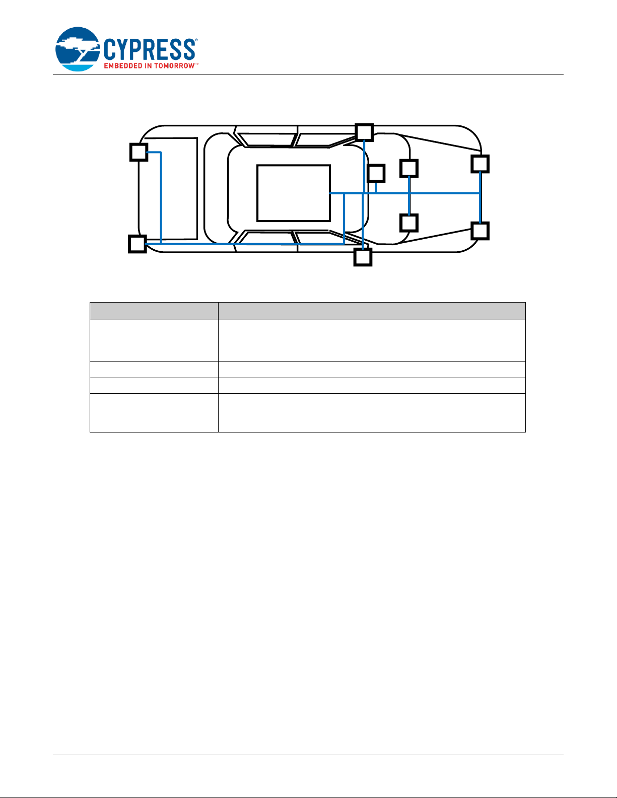
Figure 1 shows an example of the CXPI network in a vehicle.
CXPI protocol provides a low speed, low cost, and light weight connection in automotive controls of simple devices like
wipers, sensors, or switches. As an example, in Figure 1, the MCU with a CXPI controller would be the CXPI master
node whereas, the devices attached to the CXPI network would be the CXPI slave nodes. The CXPI controller can
control the devices, get status and confirmation from devices via the CXPI communication bus.
Comparing to LIN protocol, CXPI protocol provides a better performance in communication since it can handle
multiplexing between multiple devices in a more efficient manner by making the arbitration decision at the lower layer
(hardware) rather than having higher layer (software) assistance. Table 1 shows an overview of CXPI protocol feature.
Page 3
How to Use CXPI Controller in Traveo II Family
www.cypress.com Document Number: 002-24283 Rev. *B 2
Figure 1. Example of CXPI Network in a Vehicle
MCU with
CXPI
Controller
Interface
CXPI bus
Light
Light
Light
Light
Wiper
Wiper
Steering
Light
Light
Table 1. CXPI Protocol Feature
Terms
Description
Network layout
• Single master node and multiple slave nodes
• Data with clock is transmitted and received on a single communication bus
• Up to 16 nodes connected to a CXPI communication bus
Communication baud rate
Maximum baud rate of 20 kbit/s.
Network protocol
Collision Resolution supported Carrier Sense Multiple Access (CSMA/CR)
Bus access method
• Event Trigger method to support the responsiveness of slave node
communication
• Polling method to support periodic schedules
2.2 CXPI Bus Access Method
The CXPI protocol is based on a single master and multiple slave communication systems and supports two
methodologies about how and when data is transferred: Event trigger method and Polling method. In both
communication methods, only the master node provides the clock to the communication bus and all slave nodes
connected to the bus receive the clock from the communication bus and use it for communication processing. Only one
of the two methods can be implemented in all nodes connected to the CXPI communication bus:
▪
Event Trigger method: Each node can freely issue the “PID” field, if idle state of the communication bus is detected.
If several nodes transmit the PID field at the same time and the PID field collides on the communication bus, and
non-destructive arbitration is performed, then the highest priority PID field is transmitted to the communication bus.
▪
Polling method: Master node can freely issue a “PID” field to request a response from the slave nodes. Slave node
can only issue the “PID” field after receiving PTYPE sent from the master node.
The difference between the Event Trigger method and Polling method is that the Polling method requires the master
node to control the network communication by issuing PTYPE field request, which allows all nodes to issue an event
driven PID field on the communication bus. In conclusion, Polling method is suitable for a network which requires high
periodicity communications while Event Trigger method is suitable for the network that requires high responsivity to
events.
In this application note, message frame refers to the entire transmitted frame (including PID/FrameInfo/Data/CRC bytes
in one message frame) whereas byte frame refers to the byte (in terms of PID byte, FrameInfo byte, Data byte, CRC
byte individually). These terminologies will be used throughout this document.
Page 4
How to Use CXPI Controller in Traveo II Family
www.cypress.com Document Number: 002-24283 Rev. *B 3
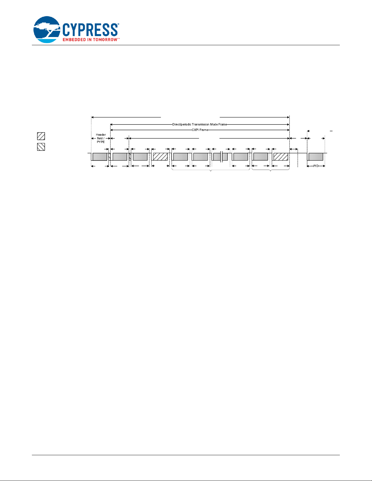
2.3 Message Frame Format
The basic CXPI frame has normal and long frames. Due to two different bus communication methods, the basic CXPI
gets an extension by an additional request field (event), usually described as PTYPE field.
Figure 2 illustrates the message frame format based on byte fields, each with a START and STOP bit and the least
significant bit (LSb) first. The Inter Byte Space (IBS) defines the idle time between two bytes within a message frame.
The Inter Frame Space (IFS) defines the period (minimum 20 Tbit) before a next frame can be transmitted by any node.
Figure 2. CXPI Message Frame Format
Header
field /
PID
CXPI bus
Response Field
Data 1 Data 2 Data N CRC
PID
FI
IBS
Normal Frame: N ≤ 12
Long Frame: N ≤ 255
IBS IBS IBSIBS IBS
IFS
DLCEXT
IBS
CRC
IBS
In long frame only
Not supported in HW
EOF
Request
field /
Header
Message frame
PTYPE
Direct-in-periodic Transmission Mode Frame
IBS
The fields of the CXPI Message frame format includes a PTYPE field (only in Polling method), a PID field, a Frame
information field, a Data Length Code Extension (DLXECT, only for Long frame), a Data field, and a CRC field.
PTYPE Field (only in Polling Method)
The 8-bit Protected Type field (PTYPE), only applicable in the Polling method, corresponds to a PID field with the
identifier value 0x00 (0x80 including parity bit). The master node sends a PTYPE byte to allow all slave nodes to send
a request field for this time slot.
Protected Identifier (PID) Field
The request field (header) consists of an 8-bit PID field, which contains a 7-bit frame identifier and a 1-bit odd parity
over the frame identifier.
Frame Information (FI) Field
As the first byte field of the response, the FI field provides information on Data Length Code (DLC), Network
Management (NM), and a frame Counter (CT).
Data Length Code Extension (only for Long frame)
A long frame can have up to 255 data bytes. In this case, the DLC of the FI field must be set to 15 and the DLCEXT
field will be present to indicate the number of data bytes in the message frames.
Data Field
The Data field can be transmitted by every node. In the normal frame, the Data field is present when DLC > 0, and can
be a maximum of 12 bytes long. In the long frame, the Data field will be present when DLC_EXT > 0 and the maximum
length is 255 bytes.
Cyclic Redundancy Check (CRC) Field
The end of a message frame consists of a CRC field and is accessible by the CRC register. The CRC length differs for
normal and long frames. For the normal frame, an 8-bit CRC polynomial is computed over the PID, FI, and Data fields.
For a long frame, a 16-bit CRC polynomial is calculated over the PID, FI, DLCEXT, and Data fields. The PTYPE field
is not included in the CRC calculation.
Page 5
How to Use CXPI Controller in Traveo II Family
www.cypress.com Document Number: 002-24283 Rev. *B 4
3 CXPI Controller in Traveo II
This section gives an overview of the CXPI Controller in Traveo II family.
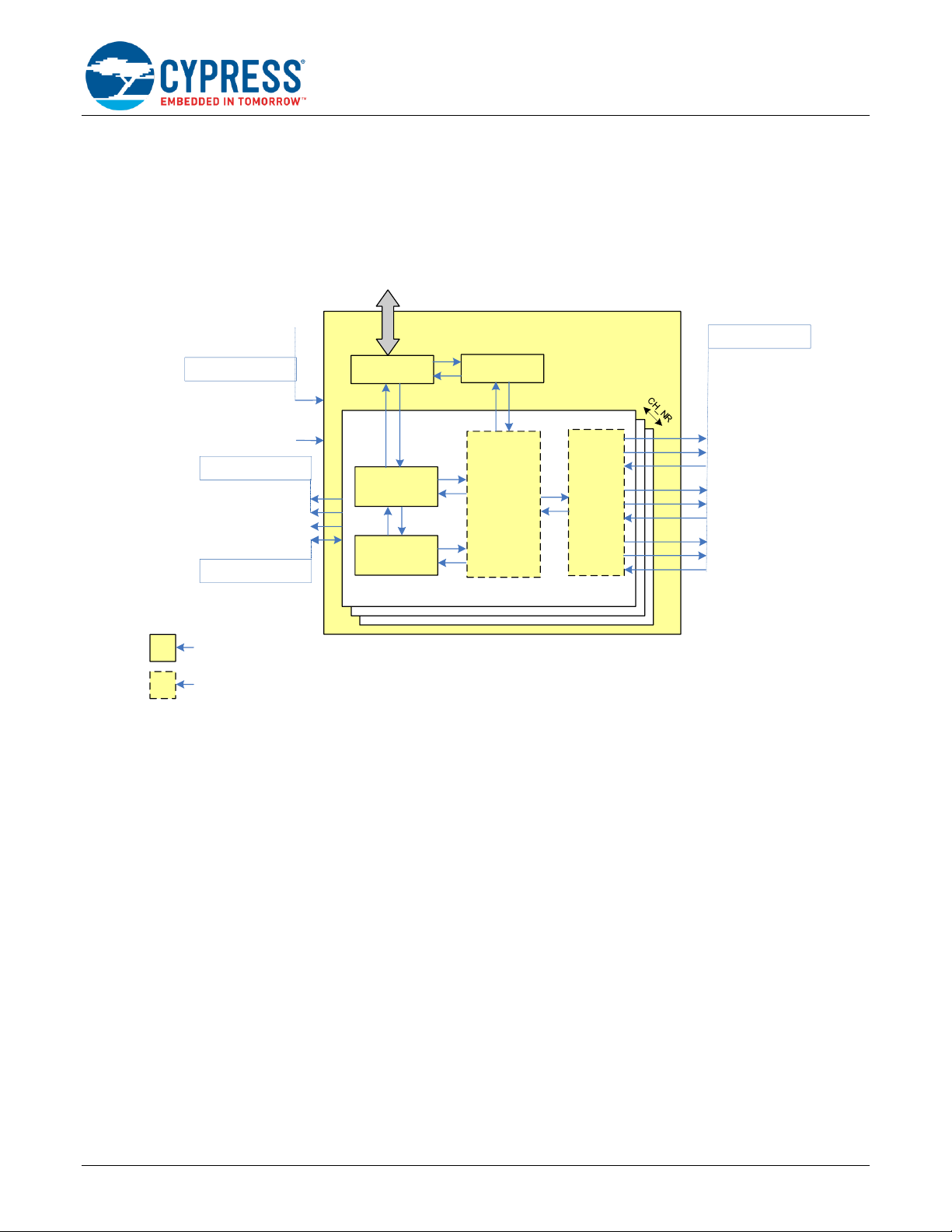
Figure 3 shows the block diagram of CXPI Controller in Traveo II. The CXPI channels are part of a common CXPI
module. Each channel has its own control, status registers, and interrupts. The total number of available CXPI channels
depends on the device variant. For details, see the device datasheet.
Figure 3. CXPI Block Diagram
CXPI Module Block
Test Registers
clk_peri
AHB
From PERI/PCLK
CXPI Channel [i]
CXPI IO
Signal
Router
Channel
Registers
cxpi_interrupts_[i]_IRQn
cxpi_en_out[i]
cxpi_rx_out[i]
cxpi_rx_in[i]
From/To IOSS/HSIOM
cxpi_tx_out[i]
cxpi_tx_in[i]
AHB Slave IF
TCPWM_TO_CXPI_TR[i]
CXPI_TR_tx_REQ[i]
CXPI_TR_tx_REQ[i]
Trigger to P-DMA
Trigger from TCPWM IP
PCLK_CXPI_CLOCK_CH_EN[i]
Definition:
i: channel
CH_NR: max. channel number
FIFO
CXPI
Controller
PCLK_CXPI_CLOCK_CH_EN[i]
clk_peri
cxpi_en_in[i]
cxpi_en_out_en[i]
cxpi_tx_out_en[i]
cxpi_rx_out_en[i]
3.1 Mode of Operation
The CXPI Controller in the Traveo II family MCU supports CXPI communication protocol in two operation modes: NRZ
mode and PWM mode.
NRZ mode is associated with CXPI controller interfacing with an external transceiver chip that has PWM
encoder/decoder logic.
PWM mode is associated with CXPI controller interfacing with an external driver/receiver chip that level shifts the
3.3 V or 5 V signaling to signaling at CXPI bus voltage without changing the encoding of the signal.
Master Node
▪
NRZ mode: When the CXPI channel is the master node (CTL0.MASTER = 1) and the CXPI transceiver does the
PWM bus signal encoding, the channel generates only the NRZ signal. As the channel does not provide the CXPI
clock signal, the clock must be generated by another module (for instance, TCPWM) separately.
▪
PWM mode: The PWM mode must be selected for the CXPI channel to process PWM signals. The PWM encoding
and decoding is done in the CXPI channel. Hence, additional device is not needed to generate the clock on the
CXPI bus.
Slave Node
▪
NRZ mode: When the CXPI channel is a slave node (CTL0.MASTER = 0) and the CXPI transceiver does the PWM
bus signal encoding/decoding, then the module must process NRZ signals.
▪
PWM mode: To process PWM signals directly, the CXPI module must be configured to the PWM mode.
Page 6

How to Use CXPI Controller in Traveo II Family
www.cypress.com Document Number: 002-24283 Rev. *B 5
3.2 Baud Rate and Sampling Concept
3.2.1 Baud Rate
The CXPI channel uses a fixed oversampling of 400. This means that the CXPI channel clock’s frequency is 400 times
the required CXPI interface frequency, i.e. baud rate of the CXPI channel. For details of sampling concept, see the
“Clock Extension Peripheral Interface (CXPI)” chapter of the Architecture TRM.
The baud rate can be configured for each channel individually. Relationship between the target baud rate and the clock
divider is shown in Equation 1.
Equation 1
Here,
▪
: Peripheral clock shown as PCLK_CXPI_CLOCK_CH_EN in Figure 3
▪
: Target baud rate
▪
: Peripheral Clock Divider for dedicated CXPI channel
To achieve the target baud rate with permitted relative tolerance of the nominal CXPI bit time, you can apply a fractional
clock divider.
Example:
Equation 2 shows an example of the divider setting value, when the peripheral clock is 80 MHz and the target baud
rate is 19.2 kbps (19.2 kHz).
Equation 2
To have the nearest divider value, choose a 16.5-bit divider with an integer divide value of 10 and a fractional divider
of 13, which has a divider value of
Equation 3
and generates
Equation 4
Applying the fractional divider results in a relative bit time tolerance of 0.1% while applying an integer divider of 10 or
11 results in relative bit time tolerance of 4.2% and 5.3% respectively.
For details on the clock divider settings and the clock tree, see the Clock System chapter in the Architecture TRM.
3.2.2 Sampling Concept
When transmitting, CXPI channels provide two registers, CTL1.T_LOW1 and CTL1.T_LOW0, to configure the low count
of logic ‘1’ and ‘0’ respectively. CTL1.T_LOW1 and CTL1.T_LOW0 indicate the number of clocks per CXPI channel to
drive a '0' at CXPI bus before releasing it to indicate a logical '1' and a logical ‘0’ respectively.
When receiving, the CXPI channel starts counting after the detection of the falling edges on the RX signal and the
register CTL1.T_OFFSET indicates value of offset that is used for sampling the RX signal.
As described before, the CXPI channel uses a fixed oversampling of 400, meaning 1 Tbit is equivalent to 400 samplings.
To achieve the target width of transmission low level when outputting logical value “1” and “0” and the sampling point
of RX signal, set value of the registers CTL1.T_LOW1, CTL1.T_LOW0, and CTL1.T_OFFSET as shown in Equation 5,
Equation 6, and Equation 7.
Equation 5
Page 7
How to Use CXPI Controller in Traveo II Family
www.cypress.com Document Number: 002-24283 Rev. *B 6
Equation 6
Equation 7
Here,
▪
: Width of transmission low level when outputting logical value “1”
▪
: Width of transmission low level when outputting logical value “0”
▪
: “cxpi_rx_in” sampling point
Example:
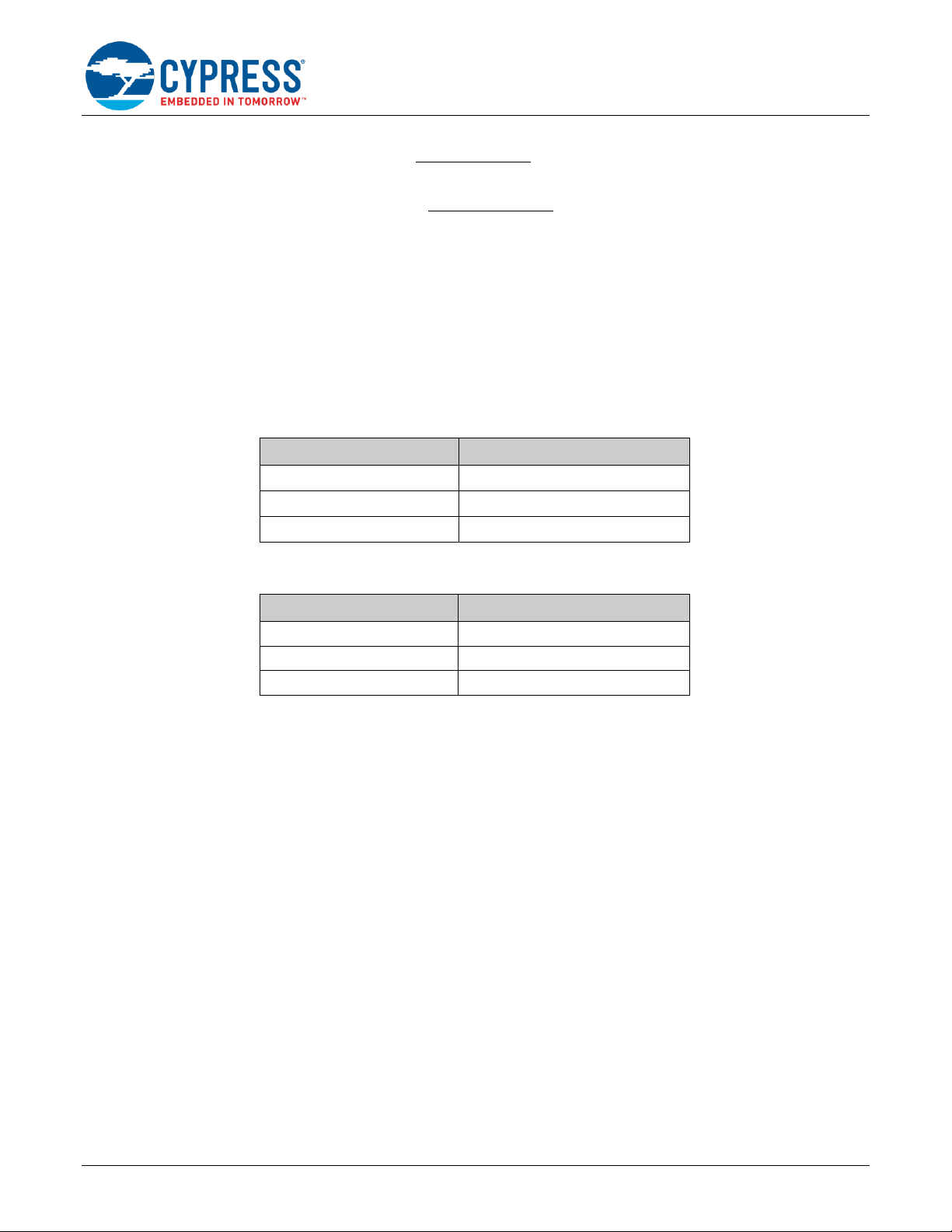
Table 2 shows the sample values set for the registers CTL1.T_LOW1, CTL1.T_LOW0, and CTL1.T_OFFSET to satisfy
timing parameters shown in Table 3.
Table 2. Timing Parameters
Item
Value
Table 3. Values of CTL1.T_LOW1, CTL1.T_LOW0, and CTL1.T_OFFSET
Item
Value
CTL1.T_LOW1
102
CTL1.T_LOW0
177
CTL1.T_OFFSET
118
3.3 CXPI Message Transmission Commands and Interrupt Events
3.3.1 Message Transfer Operation
CXPI controller supports different message types such as transmission and reception of header/response. Message
transfer processing is done by command sequences. Every command is listed in the CMD register.
Header Field Transmission/Reception supporting commands:
▪
CMD.RX_HEADER (C.RXH): This command is used to enable PTYPE and normal PID field reception.
▪
CMD.TX_HEADER (C.TXH): This command is used to request PTYPE and normal PID field transmission.
Response Field Transmission/Reception supporting commands:
▪
CMD.RX_RESPONSE (C.RXR): This command is used to enable the response field reception.
▪
CMD.TX_RESPONSE (C.TXR): This command is used to request response field transmission.
IFS check supporting command:
▪
CMD.IFS_WAIT (C.IFS): This command is used to direct HW to check bus idleness before transmitting or receiving
header.
The use case for the combination of commands to transmit/receive message frames is shown in Table 4 with
abbreviation of commands is shown along with the commands above.
Page 8

How to Use CXPI Controller in Traveo II Family
www.cypress.com Document Number: 002-24283 Rev. *B 7
Table 4. Combination of Commands 1
Transfer
Method
Master/Slave
Configuration
No.
Transaction
Setting for {C.IFS,
C.TXH, C.RXH,
C.TXR, C.RXR}
Description
Event
Trigger
Master/Slave
1
Transmit both header
(PID) and response
{1, 1, 1, 1, 1}
Master/slave in Event Trigger method uses
this combination to transmit both header (PID)
and response
In this case, HW will check for IFS before
transmitting header and response.
CMD.RX_HEADER and
CMD.RX_RESPONSE are set to 1 to
anticipate receiving PID and response while
checking the duration of bus idleness and
receiving response if arbitration is lost.
2
Transmit header (PID)
and receive response.
{1, 1, 1, 0, 1}
Master/slave in Event Trigger method uses
this combination to transmit header (PID)
CMD.RX_HEADER is set to 1 to anticipate
receiving PID while checking the duration of
bus idleness.
3
Receive both header
(PID) and response
{0, 0, 1, 0, 1}
Enable header and response reception
immediately.
4
{1, 0, 1, 0, 1}
Setting CMD.IFS_WAIT = 1 can make HW
wait for CLT0.IFS before enabling header and
response reception.
5
Transmit response only
{0, 0, 0, 0, 1}
Master/slave in Event Trigger method uses
this combination to transmit response after
receiving relevant PID
Polling
Master
6
Transmit PTYPE and
receiving header (PID)
and response
{1, 1, 1, 0, 1}
Master in Polling method uses this
combination to transmit PTYPE then receive
PID and response
7
Transmit both header
(PID) and response
{1 or 0, 1, 0, 1, 1}
Master in Polling method uses this
combination to transmit both header (PID) and
response.
Setting CMD.IFS = ‘1’ is to make sure that IFS
is checked before transmitting header but is
not mandatory.
CMD.IFS is set to 0 if master transmits PID
after transmitting PTYPE.
8
Transmit header (PID)
and receiving response
{1 or 0, 1, 0, 0, 1}
Master in Polling method uses this
combination to transmit PID and receive
response.
CMD.IFS is set to 0 if master transmits PID
after transmitting PTYPE
9
Transmit response only
{0, 0, 0, 0, 1}
Master in Polling method uses this
combination to transmit response
1
See the “Clock Extension Peripheral Interface (CXPI)” chapter of the Architecture TRM for details on the priority of these commands.
Page 9
How to Use CXPI Controller in Traveo II Family
www.cypress.com Document Number: 002-24283 Rev. *B 8
Transfer
Method
Master/Slave
Configuration
No.
Transaction
Setting for {C.IFS,
C.TXH, C.RXH,
C.TXR, C.RXR}
Description
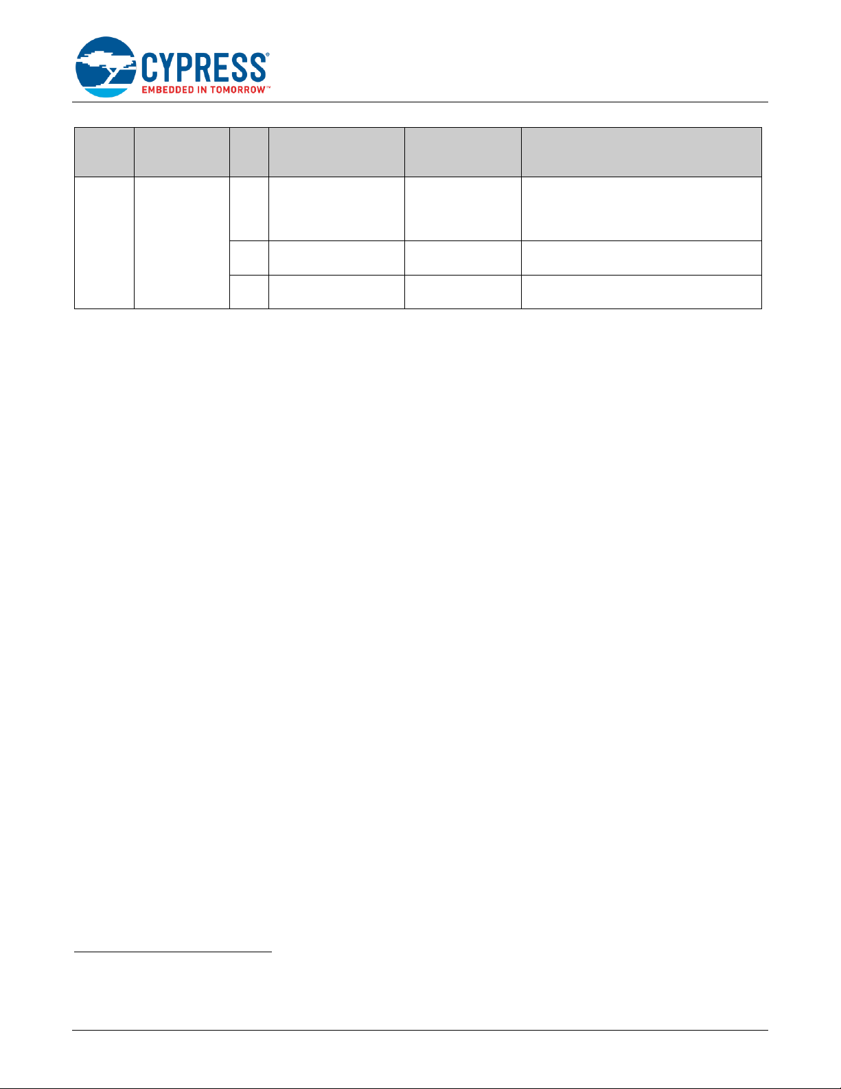
Polling
Slave
(ensure
CTL0.RXPIDZE
RO_CHECK_E
N=1) 2
10
Transmit header (PID)
and response
{0, 1, 0, 1, 1}
Slave in Polling method uses this combination
to transmit both PID and response
CMD.RX_RESPONSE is set to 1 to anticipate
receiving response after arbitration is lost.
11
Receive header (PTYPE
and PID) and response
{0, 0, 1, 0, 1}
Slave in Polling method uses this combination
to receive PTYPE/PID and response
12
Transmit response only
{0, 0, 0, 0, 1}
Slave in Polling method uses this combination
to transmit response
3.3.2 Interrupt Events
Each CXPI channel has a dedicated set of interrupt registers: INTR, INTR_SET, INTR_MASK, and INTR_MASKED. In
general, INTR registers are the interrupt event logging registers that are set by HW and cleared by SW (as part of the
interrupt service handler).
Software uses INTR_SET register to set INTR register for testing purpose. Writing ‘1’ into a bit of this register will set
the corresponding bit of INTR register.
The INTR_MASK register is used to mask interrupt sources. Only the interrupt sources with their masks enabled,
meaning corresponding bit in INTR_MASK register is set to ‘1’, can trigger the interrupt.
The INTR_MASKED register is bitwise and between the INTR and INTR_MASK. This register allows SW to read the
status of all mask-enabled interrupt causes with a single load operation.
These interrupt causes are grouped as either functional interrupts or error reporting interrupts. The following are the
functional interrupt causes:
▪
TX_HEADER_DONE: Transmission of frame header is completed.
▪
TX_RESPONSE_DONE: Transmission of frame response is completed.
▪
TX_WAKEUP_DONE: Transmission of wake up is done.
▪
TX_FIFO_TRIGGER: TX FIFO’s number of used slot is less than TRIGGER_LEVEL.
▪
RX_HEADER_DONE: Reception of frame header is completed and will be set only if reception of response is
completed.
▪
RX_HEADER_PID_DONE: This bit is set when reception of frame header is completed without waiting for the
completion of reception of response.
▪
RX_RESPONSE_DONE: Reception of frame response is completed.
▪
RX_WAKEUP_DETECT: Falling edge of RX pin in Sleep mode is detected.
▪
RX_FIFO_TRIGGER: RX FIFO’s number of used slot is greater than TRIGGER_LEVEL.
▪
TXRX_COMPLETE: HW sets this field to '1', when message frame ends after End of Frame (EOF) is confirmed
and TX/RX_DATA_LENGTH_ERROR=0.
▪
TX_HEADER_ARB_LOST: HW sets this field to '1', when it detects arbitration is lost after the number of retries
has exceeded the maximum allowed retries defined in CTL2.RETRY.
▪
TIMEOUT: HW sets this field to '1', when the transmitted/received IBS within a message frame exceeds
CTL2.TIMEOUT_LENGTH.
2
CTL0.RXPIDZERO_CHECK_EN = ‘1’ makes HW (slave) does not clear CMD.RX_HEADER and HW is able to continue receiving header coming after
PTYPE.
Page 10

How to Use CXPI Controller in Traveo II Family
www.cypress.com Document Number: 002-24283 Rev. *B 9
The following are the error reporting interrupts:
▪
TX_BIT_ERROR: HW sets this field to '1', when a transmitted "cxpi_tx_out" value does not match with a received
"cxpi_rx_in" value.
▪
RX_CRC_ERROR: HW sets this field to '1', when received CRC does not match with the CRC computed from
header and response.
▪
RX_HEADER_PARITY_ERROR: HW sets this field to '1', when the received PID field or PType field has a parity
error.
▪
RX_DATA_LENGTH_ERROR: HW sets this field to '1, when the received message frame's data fields are not
equal to the value specified in DLC (for normal frame) or DLCEXT (for long frame).
If the received message frame's data fields are greater than the value specified in DLC, it may result in
RX_CRC_ERROR error before RX_DATA_LENGTH_ERROR.
▪
TX_DATA_LENGTH_ERROR: HW sets this field to '1, when the transmitted message frame's data fields are not
equal to the value specified in DLC (for normal frame) or DLCEXT (for long frame).
▪
RX_OVERFLOW_ERROR: HW sets this field to '1', when the RX data is overwritten by HW before the SW reads
from it.
▪
TX_OVERFLOW_ERROR: HW sets this field to '1', when the TX data is overwritten by SW before the HW reads
from it to transmit on to the CXPI bus.
▪
RX_UNDERFLOW_ERROR: HW sets this field to '1', when RX FIFO is empty and SW reads from it.
▪
TX_UNDERFLOW_ERROR: HW sets this field to '1', when TX FIFO is empty and HW reads from it
▪
RX_FRAME_ERROR: HW sets this field to '1', when the stop bit of a byte frame is incorrect.
▪
TX_FRAME_ERROR: HW sets this field to '1', when the stop bit of a byte frame is incorrect.
3.4 PID Arbitration
An arbitration is done to avoid collisions between different nodes during PID field transmission. The arbitration loss is
determined through a mismatch between the transmitted header and the received header.
CXPI controller provides an automated retransmission feature, that is, the command for requesting header transmission
CMD.TX_HEADER is not cleared after losing arbitration but retained as ‘1’ to trigger the retransmission. The register
field CTL2.RETRY predefines the maximum number of PID retransmissions, whereas STATUS.RETRIES_COUNT
shows the number of retries. When the number of retransmissions exceeds CTL2.RETRY, the flag
INTR.TX_HEADER_ARB_LOST is set.
The following scenario explains the operation of software and hardware at arbitration loss:
(1) Software sets {C.IFS, C.TXH, C.RXH, C.TXR, C.RXR} = {‘1’, ‘1’, ‘1’, ‘1’, ‘1’} to request both header and response
transmission or sets {C.IFS, C.TXH, C.RXH, C.TXR, C.RXR} = {‘1’, ‘1’, ‘1’, ‘0’, ‘1’} to request header transmission
and enable response reception.
(2) Hardware transmits header and it detects lost arbitration. Hardware stops transmitting and receives the “winning”
header. Hardware notifies software that it has received PID by setting INTR.RX_HEADER_PID_DONE = ‘1’. If the
number of header transmission does not exceed CTL2.RETRY, CMD.TX_HEADER is not cleared but kept as ‘1’,
else, hardware notifies software by setting INTR.TX_HEADER_ARB_LOST flag and clears the TX_HEADER and
TX_RESPONSE command (if TX_RESPONSE is set).
CMD.TX_RESPONSE=1 has higher priority over CMD.RX_RESPONSE=1 when arbitration is “won”. However, if
arbitration is “lost”, then CMD.RX_RESPONSE has higher priority over CMD.TX_RESPONSE.
Note: There is a possibility that hardware receives a header while waiting for IFS. In this case, CMD.TX_HEADER
is cleared by hardware and INTR.TX_HEADER_ARB_LOST is not set. Software can check these two bits to
distinguish with arbitration lost case.
(3) Software reads the received header and determines the next step.
If the received PID indicates that the node that lost arbitration should receive the response.
CMD.RX_RESPONSE is set in advance, so software does nothing but wait for INTR.RX_RESPONSE_DONE
flag. After that, if arbitration lost count does not exceed the maximum number of retries defined by CTL2.RETRY,
hardware will continue to transmit the previous header.
The transmission happens after fulfilling IFS only if software sets IFS_WAIT.
Page 11

How to Use CXPI Controller in Traveo II Family
www.cypress.com Document Number: 002-24283 Rev. *B 10
If the received PID indicates that the node that lost arbitration should transmit response, software needs to
clear TX FIFO and CMD.TX_HEADER (to stop pending retry for arbitration lost). Software needs to prepare
response in TX FIFO and set CMD.TX_RESPONSE=1. Besides that, software needs to clear
CMD.RX_RESPONSE for hardware to service CMD.TX_RESPONSE command. Hardware will transmit the
response and notify software after it completes the transmission by setting INTR.TX_RESPONSE_DONE=1.
In this case, hardware will not attempt any retry for the previous header since software already cancelled the
transaction. Software needs to reprogram the previous message frame if it needs hardware to re-attempt.
STATUS.RETRIES_COUNT is also reset when software clears CMD.TX_HEADER.
4 Example of CXPI Controller Operation
This section shows an example of software implementation for the CXPI controller in Traveo II family. Figure 4 shows
an example of the CXPI controller setup flow. In this example, software will take care of PID re-transmission after
arbitration is lost.
Additionally, this example will focus on using of command sequences to perform transmission and reception of the
message frame. The use case is simplified so that there is no transmission or reception of frame whose data length is
larger than 16 bytes.
In a long frame, up to 255 data bytes are transferred/received. To avoid additional CPU access to the FIFO buffers,
every CXPI channel is connected to the P-DMA with trigger signal lines for both FIFO buffers. See the “Clock Extension
Peripheral Interface (CXPI)” chapter of the Architecture TRM for details.
(1) Initialize clock: See Baud Rate for example of clock divider setting and see the related chapter of Architecture TRM
for details on clock setting.
(2) Port settings: Enable and configure the I/O ports used for CXPI communication. Enable external CXPI transceiver
or driver/receiver before starting CXPI communication.
(3) System Interrupt Settings: Map the CXPI system interrupt source to the available external CPU interrupt.
(4) CXPI Controller initialization: See CXPI Controller Initialization for an example of CXPI Controller initialization flow.
(5) Move the CXPI controller to Normal mode. It is assumed that the CXPI bus is in active state, which means that the
wake up and sleep modes are not discussed in this application note. For details on the power modes of the CXPI
Controller, see the “Clock Extension Peripheral Interface (CXPI)” chapter of Architecture TRM.
(6) Start message transmission/reception. See Message Frame Transmission/Reception for an example of CXPI
message frame transmission/reception flow.
Figure 4. Example of the CXPI Setup Flow
Start
Initialize Clock
Initialize CXPI Controller
Port Settings
System Interrupt Settings
Message
Transmission
Move to Normal mode
(1)
(2)
(3)
(4)
(5)
(6)
Page 12

How to Use CXPI Controller in Traveo II Family
www.cypress.com Document Number: 002-24283 Rev. *B 11
4.1 CXPI Controller Initialization
Figure 5 shows an example of CXPI channel initialization flow. The following are the steps involved in initialization flow:
(1) Disable the CXPI channel.
Configure CTL0.ENABLE to “0” to disable the CXPI channel before performing initialization.
(2) Set master/slave and Mode of operation (NRZ or PWM).
Configure CTL0.MODE to”0” for NRZ mode, to “1” for PWM mode.
Configure CTL0.MASTER to “0” for slave mode, to “1” for master mode.
(3) Turn Automatic Transceiver Handling ON/OFF:
Configure CTL0.AUTO_EN to “0” to turn Automatic Transceiver Handling OFF and to “1” to turn Automatic
Transceiver Handling ON.
(4) Turn Receive PID Zero check ON/OFF.
Configure CLT0.RXPIDZERO_CHECK_EN to “1” only for slave mode in Polling method.
For other modes, set CLT0.RXPIDZERO_CHECK_EN to “0”.
(5) Turn RX filtering ON/OFF.
Configure CTL0.FILTER_EN to “0” to turn RX filtering OFF, to “1” to turn RX filtering ON.
(6) Set IFS length and IBS length.
Configure CTL0.IFS to desired Inter Frame Space in bit periods. Values lesser than 10 are not allowed.
Configure CTL0.IBS to desired Inter Byte Space in bit periods. Values greater than 9 are invalid per specification
of CXPI protocol.
(7) Turn TX Abort for bit error detection ON/OFF.
Specifies the behavior on a detected bit error during header or response transmission by setting
CTL0.BIT_ERROR_IGNORE to:
'0': Message transfer is aborted.
'1': Message transfer is NOT aborted.
(8) Define PWM pulse (only for PWM mode).
Configure CTL1.T_LOW1 and CTL2.T_LOW2 to define PWM pulse corresponding to logic “1” and logic “0”. See
Sampling Concept for example of settings.
(9) Configure sample point.
Configure CTL1.T_OFFSET to configure RX sample point. See Sampling Concept for example of settings.
(10) Define TX wake-up pulse length.
Configure CTL2.T_WAKEUP_LENGTH to specify the wake-up pulse low period in Tbits that is transmitted during
Standby mode.
(11) Select Time-out.
Configure CTL2.TIMEOUT_LENGTH to specify the number of Tbits to exceed timeout between frame bytes within
a message frame. CXPI spec states that the maximum allowed inter byte space (IBS) is 9Tbits.
Configure CTL2.TIMEOUT_SEL to one of following value:
"0" - Timeout check is disabled. HW clears timeout counter.
"1" - Timeout check is enabled and HW will refer to CTL2.TIMEOUT_LENGTH as number of Tbits allowed
between header and response.
"2" - Timeout check is enabled to check header-header, header-response, and header-header-response within
a message frame to be space within CTL2.TIMEOUT_LENGTH bit time.
(12) Set the number of retries after arbitration loss to CLT2.RETRY.
In this example, software will take care of PID re-transmission after arbitration loss, therefore, CLT2.RETRY is set
to ‘0’.
Page 13

How to Use CXPI Controller in Traveo II Family
www.cypress.com Document Number: 002-24283 Rev. *B 12
(13) Enable CXPI channel.
Configure CTL0.ENABLE to “1” to enable the CXPI channel.
Figure 5. Example of CXPI Controller Initialization Flow
Disable CXPI Channel
Set Master/SLave Mode and Mode of Operation (NRZ/
PWM)
Turn Automatic Transceiver Handling ON/OFF
Turn Receive PID Zero Check ON/OFF
Turn RX filtering ON/OFF
Set IFS length and IBS length
Turn TX Abort for Bit Error Detection ON/OFF
Define PWM Pulses (only PWM mode)
Define TX Wake-up Pulse Length
Configure Sample Point
Select Time-out
Enable CXPI Channel
CXPI Controller Initialization
END
(1)
(2)
(3)
(4)
(5)
(6)
(7)
(8)
(9)
(10)
(11)
(13)
Set Number of Retries after Arbitration Loss(12)
Page 14

How to Use CXPI Controller in Traveo II Family
www.cypress.com Document Number: 002-24283 Rev. *B 13
4.2 Message Frame Transmission/Reception
This section shows an example of CMD register usage for message frame transmission/reception. In this example, two
state variables, cxpi_state and arbitration_state, are used to manage the communication state and arbitration state.
Concretely, the setting of the command sequence is managed by two state variables.
“cxpi_state”: communication state variable has one of the following values:
▪
CXPI_STATE_TXRX_PENDING: Message frame transmission/reception pending state. This state indicates that
the message frame reception has been enabled, the node is waiting for coming message frame, or user requested
message frame transmission
▪
CXPI_STATE_TX_PTYPE: This state indicates that master node is transmitting PTYPE field. This state is available
only for the master node in Polling method.
▪
CXPI_STATE_TX_HDR_TX_RESP: This state indicates that master/slave node is transmitting both header and
response.
▪
CXPI_STATE_TX_HDR_RX_RESP: This state indicates that master/slave node is transmitting header and
receiving response.
▪
CXPI_STATE_RX_HDR_TX_RESP: This state indicates that master/slave node received a relevant PID and is
sending response.
▪
CXPI_STATE_RX_HDR_RX_RESP: This state indicates that master/slave node received a relevant PID and
continues receiving response.
“arbitration_state” arbitration state variable has one of the following values:
▪
CXPI_ARB_PENDING: Arbitration pending state. No arbitration loss is detected.
▪
CXPI_ARB_LOST_TX_RESP: Master/slave node attempted to send both header and response but lost the
arbitration.
▪
CXPI_ARB_LOST_RX_RESP: Master/slave node attempted to send a header to receive response but lost the
arbitration.
Figure 6 shows the transition of “cxpi_state”.
Page 15

How to Use CXPI Controller in Traveo II Family
www.cypress.com Document Number: 002-24283 Rev. *B 14
Figure 6. Transition of "cxpi_state"
CXPI_STATE_RX_HDR_TX_RESP
CXPI_STATE_RX_HDR_RX_RESP
CXPI_STATE_TXRX_PENDING
CXPI_STATE_TX_HDR_TX_RESP CXPI_STATE_TX_PTYPE
CXPI_STATE_TX_ HDR_RX_RESP
(1) (2) (3)
(4)
(5)
(6)
(7)
(8)
(9)
(10)
(11)
(12)
(13)
(14)
Only available in Polling method
Available in both Event trigger
method and Polling method
(0)
(initialization)
(15)
(16)
Table 5. Condition for Transition of Communication State
No
Present State
Next State
Conditions
Command
Sequence Issued
in Transition
(No. in Table 4)
(0)
(after initialization)
CXPI_STATE_TXRX_PENDING
User enables Message Frame
Reception.
No.4 or No.11
Not required for
master in Polling
method
(1)
CXPI_STATE_TXRX_PENDING
CXPI_STATE_TX_HDR_TX_RESP
User requests both header
and response transmission.
No.1, No.7, or
No.11
(2)
CXPI_STATE_TXRX_PENDING
CXPI_STATE_TX_HDR_RX_RESP
User requests both header
transmission and enables
response reception.
No.2, No.8
(3)
CXPI_STATE_TXRX_PENDING
CXPI_STATE_TX_PTYPE
User requests PTYPE field
transmission.
No.6
(4)
CXPI_STATE_TXRX_PENDING
CXPI_STATE_RX_HDR_TX_RESP
Master/slave node received a
header and the received
header indicates that this node
should transmit/receive
response.
No.5, No.9, or
No.12
(5)
CXPI_STATE_TXRX_PENDING
CXPI_STATE_RX_HDR_RX_RESP
Not required
Page 16

How to Use CXPI Controller in Traveo II Family
www.cypress.com Document Number: 002-24283 Rev. *B 15
No
Present State
Next State
Conditions
Command
Sequence Issued
in Transition
(No. in Table 4)
(6)
CXPI_STATE_TX_HDR_TX_RESP
CXPI_STATE_TXRX_PENDING
Message frame reception or
transmission is done (even in
error case). User enabled
Message Frame Reception
and this node backs to
transmission/reception
pending state.
For all nodes in
Event Trigger
method:
• No.3, if there is
no error
• No.4, if an error
occurred
• For slave node
in Polling
Method: No.11
(7)
CXPI_STATE_TX_HDR_RX_RESP
CXPI_STATE_TXRX_PENDING
(8)
CXPI_STATE_TX_PTYPE
CXPI_STATE_TXRX_PENDING
Master in Polling method
finished transmitting PTYPE.
Not required
(9)
CXPI_STATE_RX_HDR_TX_RESP
CXPI_STATE_TXRX_PENDING
Message frame reception or
transmission is completed
(even in error case). User
enable Message Frame
Reception and this node backs
to transmission/reception
pending state.
For all nodes in
Event Trigger
method:
• No.3, if there is
no error
• No.4, if error an
occurred
• For slave node
in Polling
Method: No.11
(10)
CXPI_STATE_RX_HDR_RX_RESP
CXPI_STATE_TXRX_PENDING
(11)
CXPI_STATE_TX_HDR_TX_RESP
CXPI_STATE_RX_HDR_TX_RESP
This node attempted to
transmit header but received a
header while waiting for IFS or
lost the arbitration.
The received header indicates
that this node should
transmit/receive response.
No.5
(12)
CXPI_STATE_TX_HDR_TX_RESP
CXPI_STATE_RX_HDR_RX_RESP
Not required
(13)
CXPI_STATE_TX_HDR_RX_RESP
CXPI_STATE_RX_HDR_TX_RESP
No.5
(14)
CXPI_STATE_TX_HDR_RX_RESP
CXPI_STATE_RX_HDR_RX_RESP
Not required
(15)
CXPI_STATE_TX_HDR_TX_RESP
CXPI_STATE_TX_HDR_TX_RESP
This node attempted to
transmit header but lost the
arbitration and received an
irrelevant PID. After that, the
node retries to transmit header
and transmit/receive response.
No.1
(16)
CXPI_STATE_TX_HDR_RX_RESP
CXPI_STATE_TX_HDR_RX_RESP
This node attempted to
transmit header but lost the
arbitration and received an
irrelevant PID. After that, the
node retries to transmit header
and transmit/receive response.
No.2
Page 17

How to Use CXPI Controller in Traveo II Family
www.cypress.com Document Number: 002-24283 Rev. *B 16
4.2.1 Enable Message Frame Reception
Figure 7 shows an example for enabling message frame reception.
Figure 7. Message Frame Reception Enable Flowchart
Enable Message
Frame Reception
Mask INTR Register
Set CMD
Wait for CXPI IRQ
(1)
(2)
(3)
(4)
cxpi_state =
CXPI_STATE_TXRX_
PENDING
arb_state =
CXPI_ARB_PENDING
(1) Initialize arbitration state variable
Set arb_state = CXPI_ARB_PENDING
(2) Initialize communication state variable
Set cxpi_state = CXPI_STATE_TXRX_PENDING
(3) Mask INTR register by setting INTR_MASK:
INTR_MASK.RX_HEADER_PID_DONE = ‘1’
INTR_MASK.RX_RESPONSE_DONE = ‘1’
INTR_MASK.TXRX_COMPLETE = ‘1’
(4) Set CMD (Enable Header/Frame reception)
Configure {C.IFS, C.TXH, C.RXH, C.TXR, C.RXR} = {‘0’, ‘0’, ‘1’, ‘0’, ‘1’} to enable header/frame reception.
If slave node joins the CXPI bus in the middle, configure CMD.IFS_WAIT to ‘1’ and CLT0.IFS = ‘20’ to make
hardware check for bus idleness before enabling header/frame reception.
After message reception is enabled, SW waits for occurrence of CXPI interrupt. CXPI interrupt handler is explained in
CXPI Interrupt Handle.
Page 18

How to Use CXPI Controller in Traveo II Family
www.cypress.com Document Number: 002-24283 Rev. *B 17
4.2.2 Request Message Frame Transmission
Figure 8 shows an example of request message frame transmission.
Figure 8. Flowchart for Requesting Message Frame Transmission
No
Yes
Request Message
Transmission Operation
Write Data to TX FIFO
cxpi_state =
CXPI_STATE_TX_HDR_TX
_RESP
Set CTL0.IFS
Set CMD
Wait for CXPI IRQ
cxpi_state =
CXPI_STATE_TX_HDR_RX
_RESP
Set PIDSet PID
Yes
(1)
(2)
(4)
(6)
(7.1) (7.2)
Set CTL0.IFS
Set CMD
Send PID and
Receive Response
Clear TX FIFO
Clear RX FIFO
Send both PID and
Response
Set Frame Information(5)
Mask INTR Register
Mask INTR Register
Send PTYPE only
Yes
cxpi_state =
CXPI_STATE_TX_PTYPE
Set PID
(7.2)
Set CTL0.IFS
Set CMD
Mask INTR Register
(8.1) (8.2)
(8.2)
(3)
(9.1) (9.2)
(9.2)
Only available for master
node in Polling method
Available for all nodes in
all methods
No
(1) Clear TX FIFO in advance
Configure TX_FIFO_CTL.CLEAR to ‘1’ and followed by ‘0’ to perform clearing TX FIFO
(2) Clear RX FIFO in advance
Configure RX_FIFO_CTL.CLEAR to ‘1’ and followed by ‘0’ to perform clearing RX FIFO
(3) Set the PID/PTYPE field of the header by setting TXPID_FI.PID as listed in Table 6
Page 19

How to Use CXPI Controller in Traveo II Family
www.cypress.com Document Number: 002-24283 Rev. *B 18
Table 6. PID/PTYPE Field Setting
Register
Bit
Description
TXPID_FI
PID[6:0]
PID to be transmitted
This field can be used to transmit PTYPE field as the hardware
handles both PID and PTYPE the same way, i.e. setting
TXPID_FI.PID[6:0]= 0 to transmit PTYPE field.
PID[7]
Odd parity bit and is calculated by the hardware
PID[7] = ! (ID[6] ^ ID[5] ^ ID[4] ^ ID[3] ^ ID[2] ^ ID[1] ^ ID[0])
(4) Set the Frame Information field of the response by setting TXPID_FI.FI. as listed in Table 7
Table 7: Frame Information Setting
Register
Bit
Description
TXPID_FI
FI [7:4]
Denotes the data length count (DLC).
FI [3:2]
Denotes Network Management.
FI[3] - wakeup.ind
FI[2] - sleep.ind
FI [1:0]
denotes CT
(5) Set the Data Length Code Extension field for long frame by writing the data length to TXPID_FI.DLCEXT. This field
is only valid if TXPID_FI.FI[7:4] = 4'b1111. The value specified in this field will be the new data length count. Valid
values are 0-255.
(6) Write each byte of data to TX_FIFO_WR.DATA[7:0]. Hardware shadows over the write data to TX FIFO after SW
performs a write to this field.
(7) Modify value of communication state variable ‘cxpi_state’ depending on the requested transmission.
(8) Set INTR_MASK register to enable the event interrupt according to the requested transmission:
(8.1) CXPI_STATE_TX_HDR_TX_RESP case:
INTR_MASK.TX_HEADER_DONE = ‘1’
INTR_MASK.RX_HEADER_PID_DONE = ‘1’
INTR_MASK.TX_RESPONSE_DONE = ‘1’
INTR_MASK.RX_RESPONSE_DONE = ‘1’
INTR_MASK.TXRX_COMPLETE = ‘1’
(8.2) CXPI_STATE_TX_HDR_RX_RESP case:
INTR_MASK.TX_HEADER_DONE = ‘1’
INTR_MASK.RX_HEADER_PID_DONE = ‘1’
INTR_MASK.RX_RESPONSE_DONE = ‘1’
INTR_MASK.TXRX_COMPLETE = ‘1’
(8.3) CXPI_STATE_TX_PTYPE case:
INTR_MASK.TX_HEADER_DONE = ‘1’
INTR_MASK.RX_HEADER_PID_DONE = ‘1’
INTR_MASK.RX_RESPONSE_DONE = ‘1’
INTR_MASK.TXRX_COMPLETE = ‘1’
In all cases, enable necessary error reporting interrupts by configuring the corresponding bits in INTR_MASK to ‘1’.
Page 20

How to Use CXPI Controller in Traveo II Family
www.cypress.com Document Number: 002-24283 Rev. *B 19
(9) Set the command sequence according to state according to the requested transmission.
(9.1) CXPI_STATE_TX_HDR_TX_RESP case:
Configure {C.IFS, C.TXH, C.RXH, C.TXR, C.RXR} = {‘0’ or ‘1’, ‘1’, ‘1’, ‘1’, ‘1’}
(9.2) CXPI_STATE_TX_HDR_RX_RESP case:
Configure {C.IFS, C.TXH, C.RXH, C.TXR, C.RXR} = {‘0’ or ‘1’, ‘1’, ‘1’, ‘0’, ‘1’}
(9.3) CXPI_STATE_TX_PTYPE case:
Configure {C.IFS, C.TXH, C.RXH, C.TXR, C.RXR} = {‘0’ or ‘1’, ‘1’, ‘1’, ‘0’, ‘1’}
Note: Set CMD.IFS_WAIT = ‘0’ if IFS checking is not required, i.e. transmitting header after transmitting or receiving
PTYPE.
If IFS checking is required, before setting CMD register, set CLT0.IFS to number of ‘1’ logic bit that needs to be
fulfilled before transmitting header.
After requesting message transmission, SW waits for occurrence of CXPI interrupt. CXPI interrupt handler is explained
in CXPI Interrupt Handle.
Page 21

How to Use CXPI Controller in Traveo II Family
www.cypress.com Document Number: 002-24283 Rev. *B 20
4.2.3 CXPI Interrupt Handle
This section explains the implementation of CXPI Interrupt handling (see Figure 9).
Figure 9. CXPI Interrupt Handle Flowchart
yes
Transmitting Error
Or Timeout
no
CXPI IRQ Handle
Get INTR_MASKED
Clear all Accepted interrupt
cxpi_state ==
CXPI_STATE_TX_HDR_TX_RESP or
CXPI_STATE_TX_HDR_RX_RESP
cxpi_state ==
CXPI_STATE_TXRX_
PENDING
INTR.RX_HEADER_
PID_DONE == 1
INTR.TX_HEADER_
ARB_LOST == 1
Header Reception Operation
arb_state =
CXPI_ARB_LOST_TX_RESP
or
CXPI_ARB_LOST_RX_RESP
INTR.TX_RESP_DONE == 1
Transmission of Response
is Finished
Wait for EOF
INTR.RX_RESPONSE_
DONE == 1
Reception of Response is
Finished
Read Received Response
Wait for EOF
INTR.TX_RESPONSE_
DONE == 1
Transmission of Response
is Finished
Wait for EOF
INTR.RX_RESPONSE_
DONE == 1
TXRX Completion Operation
Error Handler
cxpi_state ==
CXPI_STATE_TX_PTYPE
Request message frame
transmission operation
Continue Transmitting
Message after PTYPE
cxpi_state =
CXPI_STATE_TXRX_PEND
ING
Wait for CXPI IRQ
yes
no
yes
no
yes
no
no
yes
yes
no
no
yes
yes
no
yes
no
yes
no
yes
no
(1)
(2)
(3)
(4)
(5)
(6)
(7)
(8)
(9)
(10)
(11)
(12)
(13)
(14)
(15)
(16)
Reception of Response is
Finished
Read Received Response
Wait for EOF
(17)
(18)
(19)
(20)
(21)
(22)
(23)
Only available for master
node in Polling method
Available for all nodes in
all methods
INTR.TXRX_COMPLETE = 1
INTR.TXRX_COMPLETE = 1
cxpi_state =
CXPI_STATE_RX_HDR_TX_RESP or
CXPI_STATE_RX_HDR_RX_RESP
(1) Acquire interrupt information from INTR_MASKED register
(2) Clear all accepted interrupts
Page 22

How to Use CXPI Controller in Traveo II Family
www.cypress.com Document Number: 002-24283 Rev. *B 21
(3) Check if error occurred. If yes, go to (4)
(4) Handle error. An example flowchart of error handling is explained in section 4.2.6 Error Handler.
(5) If the current state is CXPI_STATE_TXRX_PENDING, then go to (6) to perform header reception operation. Else, go
to (7).
(6) Header reception operation. See Header Reception Operation for the software flowchart.
(7) If the current state is CXPI_STATE_TX_PTYPE, then go to (8), else go (11).
(8) PTYPE is transmitted properly, set communication state to CXPI_STATE_TXRX_PENDING.
(9) If master continues transmitting message frame after PTYPE transmission, to go (10) to request message frame
transmission. If not, master stays in transmission/reception pending state.
(10) Request message frame transmission. See Request Message Frame Transmission for the software flowchart.
(11) If the current state is CXPI_STATE_TX_HDR_TX_RESP or CXPI_STATE_TX_HDR_RX_RESP, then go to (12), else,
go to (19).
(12) Check if INTR.RX_HEADER_PID_DONE flag is set. If yes, go to (13), else go to (15).
(13) Check if INTR.TX_HEADER_ARB_LOST flag is set. If yes, this node has lost arbitration when attempting to transmit
header. Clear INTR.TX_HEADER_ARB_LOST and go to (14). If no, go to (6) to perform header reception operation.
(14) Change arbitration state variable to indicate that arbitration is lost
If arbitration is lost when transmitting both header and response, set arb_state = CXPI_ARB_LOST_TX_RESP.
If arbitration is lost when transmitting header and receiving response, set arb_state = CXPI_ARB_LOST_RX_RESP.
Then, go to (6) to perform header reception operation.
(15) Check if INTR.TX_RESPONSE_DONE flag is set. If yes, go to (16), else go to (17).
(16) Response transmission is done. Wait for hardware to confirm EOF after frame transmission, i.e. wait for
INTR.TXRX_COMPLETE flag to be set by hardware.
(17) Check if INTR.RX_RESPONSE_DONE flag is set. If yes, go to (18), else go to (23).
(18) Response reception is done. Read received response from RX FIFO and wait for hardware to confirm EOF after frame
reception, i.e. wait for INTR.TXRX_COMPLETE flag to be set by hardware.
(19) Check if INTR.TX_RESPONSE_DONE flag is set. If yes, go to (20), else go to (21).
(20) Response transmission is done. Wait for hardware to confirm EOF after frame response transmission, i.e. wait for
INTR.TXRX_COMPLETE flag to be set by hardware.
(21) Check if INTR.RX_RESPONSE_DONE flag is set. If yes, go to (22), else go to (23).
(22) Response reception is done. Read received response in RX FIFO and wait for hardware to confirm EOF after frame
reception, i.e. wait for INTR.TXRX_COMPLETE flag to be set by hardware.
(23) Hardware confirmed EOF after frame ends without data length error. See TXRX Completion Operation for example
of software flowchart.
Page 23

How to Use CXPI Controller in Traveo II Family
www.cypress.com Document Number: 002-24283 Rev. *B 22
4.2.4 Header Reception Operation
Figure 10 shows an example flowchart for header reception.
Figure 10. Header Reception Flowchart
Header Reception Operation
no
Prepare response data
Mask INTR register
Set CMD
Wait for CXPI IRQ
yes
Transmit Response?
Relevant PID?
arb_state==
CXPI_ARB_LOST_TX_
RESP
Clear TX FIFO
arb_state==
CXPI_ARB_LOST_TX_RESP or
CXPI_ARB_LOST_RX_RESP
Retry to transmit
Message frame
Set CTL0.IFS
Set CMD
Mask INTR register
cxpi_state =
CXPI_STATE_RX_HDR_
TX_RESP
cxpi_state =
CXPI_STATE_RX_HDR_
RX_RESP
cxpi_state =
CXPI_STATE_TXRX_
PENDING
Received PTYPE?
Request message
transmission?
Request message
transmission operation
(2)
(3)
(4)
(5)
(6)
(8)
(9)
(10)
(11)
(12)
(14-1)
(14-3)
(15-1)
(15-3)
(13-1) (13-2) (13-3)
Only available for slave
node in Polling method
Available for all node in
all methods
Read received header(1)
yes
yes
yes
yes
no
no
no
no
yes
yes
no
Clear CMD.RX_RESP
(7)
Page 24

How to Use CXPI Controller in Traveo II Family
www.cypress.com Document Number: 002-24283 Rev. *B 23
(1) Read the received header by reading the RXPID_FI.PID field:
RXPID_FI.PID[6:0] shows received PID/PTYPE.
RXPID_FI.PID[7] shows received odd parity bit.
(2) If PTYPE is received, go to (3), else if normal PID is received then go to (5).
(3) If there is a request message for frame transmission, go to (4), if no continue waiting for header/response.
(4) Request message frame transmission. The flowchart is shown in Request Message Frame Transmission.
Note that IFS checking is not required before transmitting PID after receiving PTYPE.
(5) Check if the received PID is a relevant PID.
If yes, go to (8) to check if transmission of response is needed.
If no, go to (6) to clear CMD.RX_RESP.
(6) Clear CMD.RX_RESP to stop receiving response.
(7) Check if PID arbitration is lost by checking arbitration state variable.
If yes, go to (8) to request message frame re-transmission.
If no, go to (13-3) to move hardware back to transmission/reception pending state.
(8) At this stage, arbitration is lost and the “won” PID is received, but the received PID can be ignored. Check if PID
that lost arbitration needs to be re-transmitted. If yes, go to (4) to request message frame transmission, else go to
(13-3).
(9) If the received PID indicates that this node should transmit response, go to (10), else go to (13-2).
(10) Check if PID arbitration is lost during the attempt to transmit both header and response. If yes,
CMD.TX_RESPONSE is still set to ‘1’ and TX FIFO is still filled by old response data, therefore go to (11). If no,
go to (12).
(11) Clear TX FIFO:
Configure TX_FIFO_CTL.CLEAR to ‘1’ and followed by ‘0’ to perform clearing TX FIFO.
(12) Prepare response to be transmitted by writing each byte of response to TX_FIFO_WR.DATA[7:0].
(13) Modify value of communication state variable ‘cxpi_state’ depending on the requested transmission.
(14) Set INTR_MASK register to enable the event interrupt according to the transmission:
(14-1) CXPI_STATE_RX_HDR_TX_RESP
INTR_MASK.TX_RESPONSE_DONE = ‘1’
INTR_MASK.TXRX_COMPLETE = ‘1’
(14-3) CXPI_STATE_TXRX_PENDING case
INTR_MASK.RX_HEADER_PID_DONE = ‘1’
INTR_MASK.RX_RESPONSE_DONE = ‘1’
INTR_MASK.TXRX_COMPLETE = ‘1’
(15) Set the command sequence according to state according to the requested transmission:
(15-1) CXPI_STATE_RX_HDR_TX_RESP
Configure {C.IFS, C.TXH, C.RXH, C.TXR, C.RXR} = {‘0’, ‘0’, ‘0’, ‘1’, ‘0’}.
(15-3) CXPI_STATE_TXRX_PENDING
Configure CLT0.IFS = ‘20’.
Configure {C.IFS, C.TXH, C.RXH, C.TXR, C.RXR} = {‘1’, ‘0’, ‘1’, ‘0’, ‘1’} to enable header/frame reception.
Page 25

How to Use CXPI Controller in Traveo II Family
www.cypress.com Document Number: 002-24283 Rev. *B 24
CMD.IFS_WAIT is set to ‘1’to make the hardware wait for 20Tbit of logic ‘1’ before enabling header/frame
reception.
4.2.5 TXRX Completion Operation
Figure 11 shows an example flowchart for TXRX completion, indicating a finished message transfer independently if
the transfer had an error.
Figure 11. TXRX Completion Flowchart
TXRX Completion Operation
Set CMD
Mask INTR Register
Wait for CXPI IRQ
cxpi_state ==
CXPI_STATE_TX_HDR_TX_RESP or
CXPI_STATE_TX_HDR_RX_RESP
Request Message Frame
Transmission Operation
Retry to transmit
Message frame?
cxpi_state =
CXPI_STATE_TXRX_
PENDING
arb_state==
CXPI_ARB_LOST_TX_RESP or
CXPI_ARB_LOST_RX_RESP
arb_state =
CXPI_ARB_PENDING
(1)
Yes
No
(2)
(3)
(4)
(5)
yes
yes
No
No
(6)
(7)
(9)
(8)
cxpi_state =
CXPI_STATE_TXRX_
PENDING
cxpi_state =
CXPI_STATE_RX_HDR_TX_RESP or
CXPI_STATE_RX_HDR_RX_RESP
(1) If the current state is CXPI_STATE_TX_HDR_TX_RESP or CXPI_STATE_TX_HDR_RX_RESP then go to (2).
Else, current state is CXPI_STATE_RX_HDR_TX_RESP or CXPI_STATE_RX_HDR_RX_RESP, go to (6).
(2) Reset arb_state to CXPI_ARB_PENDING.
(3) Reset cxpi_state to CXPI_STATE_TXRX_PENDING.
(4) Mask INTR register:
INTR_MASK.RX_HEADER_PID_DONE = ‘1’
INTR_MASK.RX_RESPONSE_DONE = ‘1’
INTR_MASK.TXRX_COMPLETE = ‘1’
(5) Set CMD register:
Configure {C.IFS, C.TXH, C.RXH, C.TXR, C.RXR} = {‘0’, ‘0’, ‘1’, ‘0’, ‘1’} to enable header/frame reception.
(6) Check if arbitration is lost by checking arb_state. If yes, go to (8), else go to (2).
Page 26

How to Use CXPI Controller in Traveo II Family
www.cypress.com Document Number: 002-24283 Rev. *B 25
(7) Arbitration lost. Check if message frame retransmission is required. If yes, go to (9) to request message frame
transmission. If not, go to (2).
(8) Set cxpi_state to CXPI_STATE_TXRX_PENDING.
(9) Request message frame transmission. See Request Message Frame Transmission for the software flowchart.
4.2.6 Error Handler
Figure 12 shows an example of error handling implementation.
Figure 12. Flowchart for Error Handling
Error Handler
User defined Error Handle
Set CLT0.IFS
Set CMD
Mask INTR register
cxpi_state =
CXPI_STATE_TXRX_
PENDING
Wait for CXPI IRQ
arb_state =
CXPI_ARB_PENDING
Clear CMD(1)
(2)
(3)
(4)
(5)
(6)
(1) Clear CMD register to stop requesting transmission/reception.
(2) Reset arbitration state variable:
arb_state = CXPI_ARB_PENDING
(3) Reset communication state variable:
cxpi_state = CXPI_STATE_TXRX_PENDING
(4) Mask INTR register by setting INTR_MASK:
INTR_MASK.RX_HEADER_PID_DONE = ‘1’
INTR_MASK.RX_RESPONSE_DONE = ‘1’
INTR_MASK.TXRX_COMPLETE = ‘1’
(5) Set CLT0.IFS then set CMD register to enable header/response reception:
Configure {C.IFS, C.TXH, C.RXH, C.TXR, C.RXR} = {‘0’, ‘0’, ‘1’, ‘0’, ‘1’} to enable header/frame reception.
(6) Execute the error handler defined by user.
Page 27

How to Use CXPI Controller in Traveo II Family
www.cypress.com Document Number: 002-24283 Rev. *B 26
5 Glossary
Terms
Description
CXPI
Clock Extension Peripheral Interface
NRZ mode
Non-Return-to-Zero mode. CXPI controller interfacing with external transceiver chip that has PWM
encoder/decoder logic
PWM mode
CXPI controller interfacing with external driver chip that level shifts the 3.3 V or 5 V signaling to 12 V CXPI
signaling without changing the encoding of the signal
GPIO
General Purpose Input/Output
AUTOSAR
AUTomotive Open System ARchitecture
Header
Consists of PID field and PTYPE field transmitted by the master and the slave. PTYPE can only be
transmitted by the master in polling method. See the CXPI Message Frame Format section in the CXPI
chapter of the Architecture TRM for details.
Response
Consists of frame information, data fields and CRC field, transmitted by the master and the slave. See the
CXPI Message Frame Format section in the CXPI chapter of the Architecture TRM for details.
PID
Protected Identifier field
PTYPE
The 8-bit Protected Type field (PTYPE), only applicable in the Polling Method, corresponds to a PID field with
the identifier value 0x00 (0x80 included parity bit)
CRC
Cyclic Redundancy Check field.
PERI clock
PERipheral Interconnect clock
IRQ
Interrupt ReQuest
6 Related Documents
The following are the Traveo II family series datasheets and Technical Reference Manuals. Contact Technical Support
to obtain these documents.
▪
Device datasheet
CYT2B9 Datasheet 32-Bit Arm® Cortex®-M4F Microcontroller Traveo™ II Family
CYT3DL Datasheet 32-Bit Arm® Cortex®-M7 Microcontroller Traveo™ II Family
CYT4DN Datasheet 32-Bit Arm® Cortex®-M7 Microcontroller Traveo™ II Family
▪
Body Controller Entry Family
Traveo™ II Automotive Body Controller Entry Family Architecture Technical Reference Manual (TRM)
Traveo™ II Automotive Body Controller Entry Registers Technical Reference Manual (TRM) for CYT2B9
▪
Cluster 2D Family
Traveo™ II Automotive Cluster 2D Family Architecture Technical Reference Manual (TRM)
Traveo™ II Automotive Cluster 2D Registers Technical Reference Manual (TRM)
Page 28

How to Use CXPI Controller in Traveo II Family
www.cypress.com Document Number: 002-24283 Rev. *B 27
Document History
Document Title: AN224283 - How to Use CXPI Controller in Traveo II Family
Document Number: 002-24283
Revision
ECN
Submission
Date
Description of Change
**
6459396
07/10/2019
New application note
*A
6726411
11/08/2019
Added target parts number (CYT4D series)
*B
6905363
06/25/2020
Changed target parts number (CYT2/CYT3/CYT4 series)
Page 29

How to Use CXPI Controller in Traveo II Family
www.cypress.com Document Number: 002-24283 Rev. *B 28
Worldwide Sales and Design Support
Cypress maintains a worldwide network of offices, solution centers, manufacturer’s representatives, and distributors. To find the
office closest to you, visit us at Cypress Locations.
Products
Arm® Cortex® Microcontrollers
cypress.com/arm
Automotive
cypress.com/automotive
Clocks & Buffers
cypress.com/clocks
Interface
cypress.com/interface
Internet of Things
cypress.com/iot
Memory
cypress.com/memory
Microcontrollers
cypress.com/mcu
PSoC
cypress.com/psoc
Power Management ICs
cypress.com/pmic
Touch Sensing
cypress.com/touch
USB Controllers
cypress.com/usb
Wireless Connectivity
cypress.com/wireless
PSoC® Solutions
PSoC 1 | PSoC 3 | PSoC 4 | PSoC 5LP | PSoC 6 MCU
Cypress Developer Community
Community | Code Examples | Projects | Videos | Blogs |
Training | Components
Technical Support
cypress.com/support
All other trademarks or registered trademarks referenced herein are the property of their respective owners.
© Cypress Semiconductor Corporation, 2019-2020. This document is the property of Cypress Semiconductor Corporation and its subsidiaries (“Cypress”). This
document, including any software or firmware included or referenced in this document (“Software”), is owned by Cypress under the intellectual property laws and
treaties of the United States and other countries worldwide. Cypress reserves all rights under such laws and treaties and does not, except as specifically stated in
this paragraph, grant any license under its patents, copyrights, trademarks, or other intellectual property rights. If the Software is not accompanied by a license
agreement and you do not otherwise have a written agreement with Cypress governing the use of the Software, then Cypress hereby grants you a personal, nonexclusive, nontransferable license (without the right to sublicense) (1) under its copyright rights in the Software (a) for Software provided in source code form, to
modify and reproduce the Software solely for use with Cypress hardware products, only internally within your organization, and (b) to distribute the Software in binary
code form externally to end users (either directly or indirectly through resellers and distributors), solely for use on Cypress hardware product units, and (2) under
those claims of Cypress’s patents that are infringed by the Software (as provided by Cypress, unmodified) to make, use, distribute, and import the Software solely
for use with Cypress hardware products. Any other use, reproduction, modification, translation, or compilation of the Software is prohibited.
TO THE EXTENT PERMITTED BY APPLICABLE LAW, CYPRESS MAKES NO WARRANTY OF ANY KIND, EXPRESS OR IMPLIED, WITH REGARD TO THIS
DOCUMENT OR ANY SOFTWARE OR ACCOMPANYING HARDWARE, INCLUDING, BUT NOT LIMITED TO, THE IMPLIED WARRANTIES OF
MERCHANTABILITY AND FITNESS FOR A PARTICULAR PURPOSE. No computing device can be absolutely secure. Therefore, despite security measures
implemented in Cypress hardware or software products, Cypress shall have no liability arising out of any security breach, such as unauthorized access to or use of
a Cypress product. CYPRESS DOES NOT REPRESENT, WARRANT, OR GUARANTEE THAT CYPRESS PRODUCTS, OR SYSTEMS CREATED USING
CYPRESS PRODUCTS, WILL BE FREE FROM CORRUPTION, ATTACK, VIRUSES, INTERFERENCE, HACKING, DATA LOSS OR THEFT, OR OTHER
SECURITY INTRUSION (collectively, “Security Breach”). Cypress disclaims any liability relating to any Security Breach, and you shall and hereby do release
Cypress from any claim, damage, or other liability arising from any Security Breach. In addition, the products described in these materials may contain design
defects or errors known as errata which may cause the product to deviate from published specifications. To the extent permitted by applicable law, Cypress reserves
the right to make changes to this document without further notice. Cypress does not assume any liability arising out of the application or use of any product or circuit
described in this document. Any information provided in this document, including any sample design information or programming code, is provided only for reference
purposes. It is the responsibility of the user of this document to properly design, program, and test the functionality and safety of any application made of this
information and any resulting product. “High-Risk Device” means any device or system whose failure could cause personal injury, death, or property damage.
Examples of High-Risk Devices are weapons, nuclear installations, surgical implants, and other medical devices. “Critical Component” means any component of a
High-Risk Device whose failure to perform can be reasonably expected to cause, directly or indirectly, the failure of the High-Risk Device, or to affect its safety or
effectiveness. Cypress is not liable, in whole or in part, and you shall and hereby do release Cypress from any claim, damage, or other liability arising from any use
of a Cypress product as a Critical Component in a High-Risk Device. You shall indemnify and hold Cypress, its directors, officers, employees, agents, affiliates,
distributors, and assigns harmless from and against all claims, costs, damages, and expenses, arising out of any claim, including claims for product liability, personal
injury or death, or property damage arising from any use of a Cypress product as a Critical Component in a High-Risk Device. Cypress products are not intended
or authorized for use as a Critical Component in any High-Risk Device except to the limited extent that (i) Cypress’s published data sheet for the product explicitly
states Cypress has qualified the product for use in a specific High-Risk Device, or (ii) Cypress has given you advance written authorization to use the product as a
Critical Component in the specific High-Risk Device and you have signed a separate indemnification agreement.
Cypress, the Cypress logo, Spansion, the Spansion logo, and combinations thereof, WICED, PSoC, CapSense, EZ-USB, F-RAM, and Traveo are trademarks or
registered trademarks of Cypress in the United States and other countries. For a more complete list of Cypress trademarks, visit cypress.com. Other names and
brands may be claimed as property of their respective owners.
 Loading...