

Cynix SE-N22DC SE Series, SE-P22DC SE Series Instruction Manual

INSTRUCTION MANUAL Ver 1. 0
Speed Dome Camera / SE Series
Speed Dome Camera Instruction Manual
2/35
This lightning flash with arrowhead symbol is intended to alert the user to the
presence of uninsulated "dangerous voltage" within the product's enclosure that
may be of sufficient magnitude to constitute a risk of electric shock to persons.
This exclamation point symbol is intended to alert the user to the presence of
important operating and maintenance (servicing) instructions in the literature
accompanying the appliance.

Speed Dome Camera Instruction Manual
3/35
Important Safeguard
1. Read Instructions
Read all of the safety and operating instructions before using the product.
2. Retain Instructions
Save these instructions for future reference.
3. Attachments / Accessaries
Do not use attachments or accessories unless recommended by the appliance manufacturer as they may
cause hazards, damage product and void warranty.
4. Water and Moisture
Do not use this product near water or moisture.
5. Installation
Do not place or mount this product in or on ana unstable or improperly supported location. Improperly
installed product may fall, causing serious injury to a child or adult, and damage to the product. Use only
with a mounting device recommended by the manufacturer, or sold with the product. To insure proper
mounting, follow the manufacturer's instructions and use only mounting accessories recommended by
manufacturer.
6. Power source
This product should be operated only from the type of power source indicated on the marking label.
Precautions
Operating
z Before using, make sure power supply and others are properly connected.
z While operating, if any abnormal condition or malfunction is observed, stop using the camera
immediately and then contact your local dealer.
Handling
z Do not disassemble or tamper with parts inside the camera.
z Do not drop or subject the camera to shock and vibration as this can damage camera.
z Care must be taken when you clean the clear dome cover. Especially, scratch and dust will ruin your
quality of camera.
Installation and Storage
z Do not install the camera in areas of extreme temperature, which exceed the allowable range.
z Avoid installing in humid or dusty places.
z Avoid installing in places where radiation is present.
z Avoid installing in places where there are strong magnetic fields and electric signals.
z Avoid installing in places where the camera would be subject to strong vibrations.
z Never expose the camera to rain and water.
NOTICENOTICENOTICENOTICENOTICENOTICENOTICENOTICENOTICENOTICENOTICENOTICENOTICENOTICENOTICENOTICENOTICE

Speed Dome Camera Instruction Manual
4/35
○
1
Introduction
Features 5
Product & Accessories
6
Parts Name & Functions
7
○
2
Installation
Rear Bracket Disassembling / Assembling 8
DIP Switch Setup
9
Direct Installation on the Ceiling
12
Installation using In-Ceiling Mount Bracket
13
Installation using Ceiling Mount Bracket
15
Installation using Wall Mount Bracket 16
Cabling
17
○
3
Operation
Checking Before Operation 19
Start OSD Menu
20
Reserved Preset
20
Relay Output Control 20
Preset
21
Swing
21
Group 22
Other Motion Functions
23
OSD Display of Main Screen
24
○
4
How to use OSD Menu
General Rules of Menu Operation 25
Main Menu
25
Display Menu for Main Screen
25
Camera Module Setup
26
Motion Setup
26
Preset Setup
28
Swing Setup
30
Group Setup
31
○5 Specifications
SE-N(P)22CC 32
SE-N(P)22DC
33
Dimension 34
CONTENTS

Speed Dome Camera Instruction Manual
5/35
Fe at u re s
Camera Specifications
z CCD Sensor : 1/4" Super HAD CCD
z Zoom Magnification : × 22 Optical Zoom, × 10 Digital Zoom (Max. × 220 Zoom in Total)
z Day & Night Function → SE-x22DC Model
Powerful Pan/Tilt Functions
z Max. 240°/sec high speed Pan/Tilt Motion
z Using Vector Drive Technology, Pan/Tilt motions are accomplished in a shortest path. As a result,
time to target view is reduced dramatically and the video on the monitor is very natural to watch.
z For jog operation using a controller, since ultra slow speed 0.1°/sec can be reached, it is very easy
to locate camera to desired target view.
Preset, Swing and Group Functions
z Max. 64 sets of position and zoom magnification are designated and stored as Preset. For each
Preset, additional information such as Dwell time (pause time in Group action when camera reaches
to a certain Preset position), Alarm action and area Label can be assigned independently to meet to
your requirements.
z 8 of Swing action can be stored. This enables to move camera repetitively between two preset
positions with designated speed.
z 8 set of Group action can be stored. This enables to move camera repetitively with combination of
Preset or Swing. A Group is composed of max. 20 entities of Preset or Swings.
PTZ Control
z With RS-485 communication, max. 255 of cameras can be controlled at the same time.
z Pelco-D or Pelco-P protocol can be selected as a control protocol in the current version of firmware.
OSD(On Screen Display) Menu
z OSD menu is provided to display the status of camera and to configure the functions interactively.
z The information such as Camera ID, Pan/Tilt angle, Alarm I/O, Preset info can be displayed on the
screen.
Alarm I/O Functions
z 2 alarm sensor Inputs and 2 alarm Output relays are available.
z To reject external electric noise and shock perfectly, alarm sensor Input is decoupled with photo
coupler and the relay is used for alarm output.
z The signal range of sensor input is from DC 5.0 to 12.0 volts to adopt various applications.
Meanwhile, the maximum load of relay contact is AC 250V, 5A or DC 28V, 5A.
z If an external sensor is activated, camera can be set to move to the corresponding Preset position.
Meanwhile, the output relay can be matched to some specific Preset positions to do counteractions
such as turning on the light or sound the alarm.
INTRODUCTION
1 1
Speed Dome Camera Instruction Manual
6/35
Product & Accessories
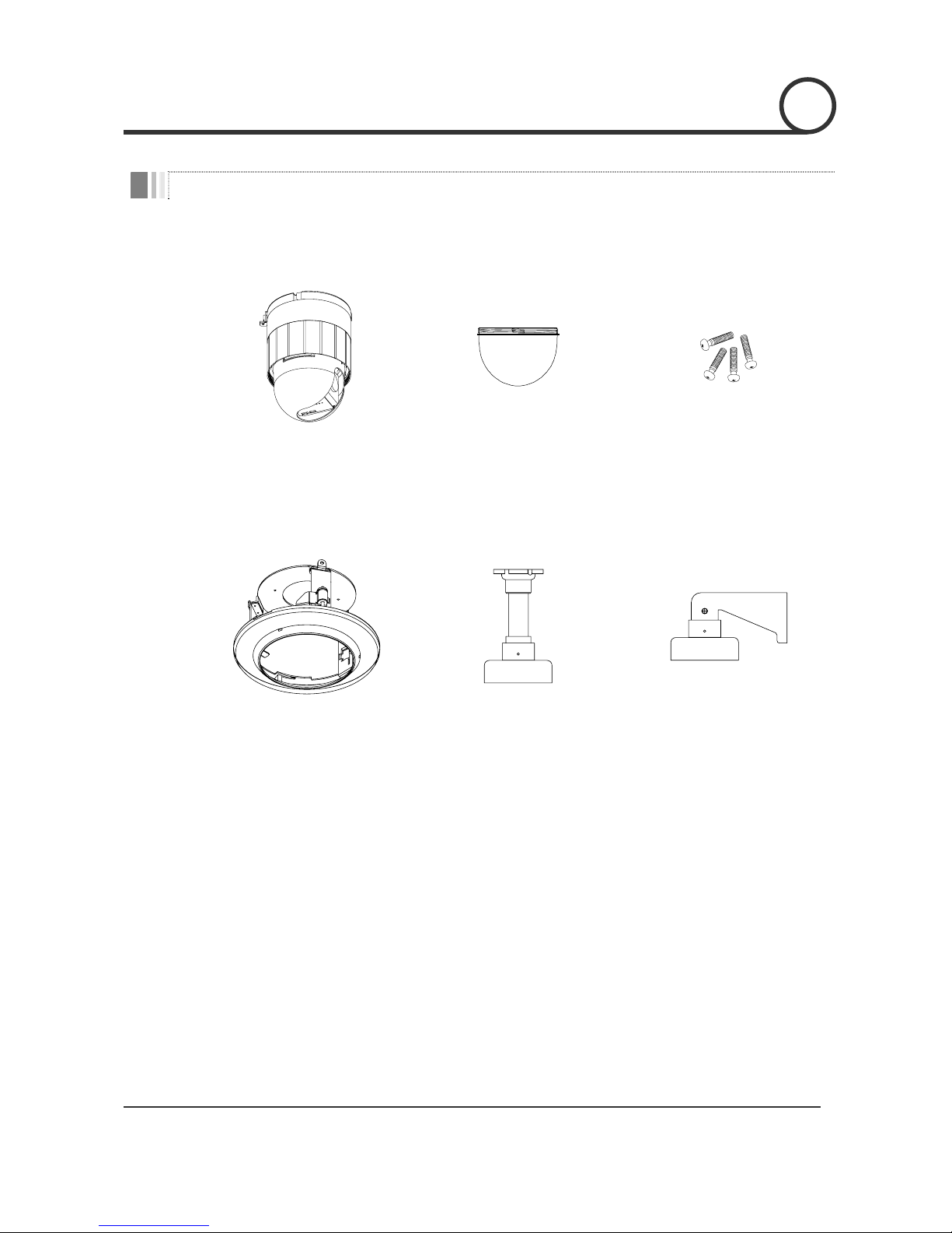
Product & Accessories
z Camera Body z Dome Cover z Screws
Options
z In-Ceiling Mount Bracket
(SBI-100)
z Ceiling Mount Bracket
(SBC-100)
z Wall mount bracket
(SBW-100)
INTRODUCTION
1
Speed Dome Camera Instruction Manual
7/35
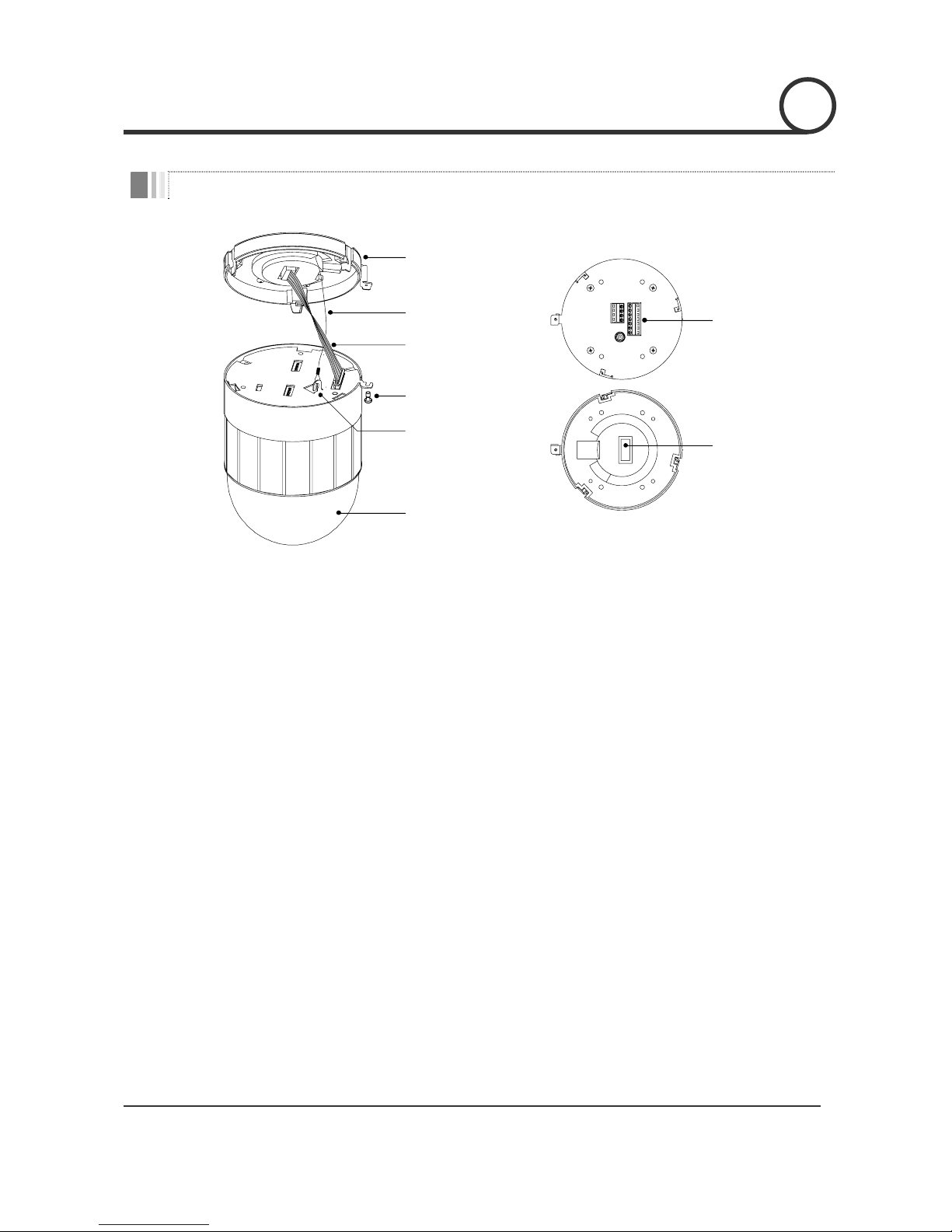
Parts Name & Functions
Rear Bracket
Lockup Screw
Dome Cover
Drop Prevention
Spring
Drop Prevention
Hook
Signal Cable
Fuse
Cabling
Terminal Block
z Main Body z Rear Bracket
z Dome Cover
Care must be taken when you clean the clear dome cover. Since
scratch, finger print and dust on the dome cover will ruin quality of
camera, do not remove the vinyl tape on cover before installation is
completed.
z Rear Bracket
This rear bracket is used to install the camera directly on the ceiling or
attach to the other brackets such as wall, ceiling, and outdoor mount.
After separating this bracket first and then attach this directly to ceiling
or to the other bracket. Camera must be assembled at the last stage.
z Drop Prevention Spring
Drop Prevention Hook
This part keeps the camera from dropping during installation and
maintenance. After install the Rear Bracket, please, hang the spring to
the drop prevention hook of main body as shown in picture for further
tasks.
z Signal Cable
Do not forget to connect this cable before you assemble Rear bracket
and Main body of camera.
z Lockup Screw
Tighten this screw to fix the camera into the bracket after you assemble
Rear bracket and Main body by turning the Main body.
z Fuse
If the fuse is burnt to protect your came from over-current damage, the
fuse have to be replace with new one. The fuse specification is 250V 2A.
However, we recommend consulting with supplier to remove the cause
of over-current.
z Cabling Terminal Block
During installation, Power, Video, Communication, Alarm I/O cables are
connected on to this cabling terminal block.
INTRODUCTION
1
Speed Dome Camera Instruction Manual
8/35
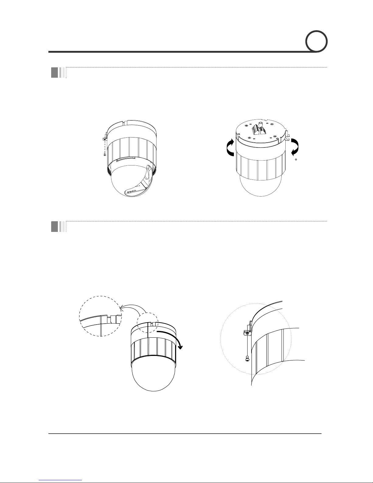
Rear Bracket Disassembling
① Remove the fixing screw as shown bellow. ② Dismantle the Rear bracket by turning main
body about 15°.
15
Rear Bracket Assembling
① After you locate the internal cable properly, place
the Rear Bracket on to Main body by considering
the matching line of both parts as show in picture
bellow. Then, slightly turn the Rear Bracket
clockwise to assemble.
② Tighten the fixing screw as shown bellow.
INSTALLATION
2
Speed Dome Camera Instruction Manual
9/35
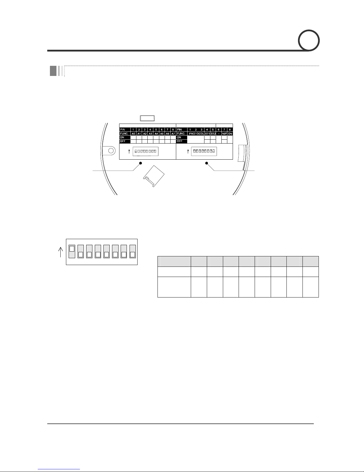
DIP Switch Setup
Before you install the camera, you should set the DIP switches to configure the camera ID, communication
protocol.
1 2 4 8 16 32 64 128
ON
N.C N.C PAL
N.O N.O
NTSC
Refer to
the Manual
0000 0000
ON
OPTIONS
ADDRESS (ID)
RESERVED
Communication Protocol
Sensor Type
Camera ID
Camera ID Setup
123456
ON
ON
78
z ID number of camera is set using binary number. The example is
shown bellow.
Pin 1 2 3 4 5 6 7 8
ID Value 1 2 4 8 16 32 64 128
ex) ID=5 on off on off off off off off
ex) ID=10 off on off on off off off off
z The range of ID is 1~255. Do not use 0 as camera ID. Factory default
of Camera ID is 1.
z If you want to control a certain camera, you must match the camera
ID with Cam ID setting of DVR or Controller. Don’t forget Camera ID.
2
INSTALLATION

Speed Dome Camera Instruction Manual
10/35
Communication Protocol Setup
123456
ON
O
N
78
Sensor Type Setup
123456
ON
ON
78
z Select the appropriate Protocol with DIP switch combination.
Switch State
Pin 1 Pin 2 Pin 3
Protocol/Baud rate
OFF OFF OFF PELCO-D, 2400 bps
ON OFF OFF PELCO-D, 9600 bps
OFF ON OFF PELCO-P, 4800 bps
ON ON OFF PELCO-P, 9600 bps
Otherwise Reserved
z If you want to control using DVR or P/T controller, their protocol must
be identical to camera. Otherwise, you can not control the camera.
z If you changed camera protocol by changing DIP S/W, the change
will be effective after you reboot the camera.
z Factory default of protocol is ‘Pelco-D, 2400 bps.
z If you want to use Alarm Input, the types of sensor must be selected.
The sensor types are Normal Open and Normal.
~ Normal Open Output Voltage is high state when sensor is
activated.
~ Normal Close Output Voltage is high state when sensor is not
activated.
Pin No. Switch State Sensot Type
ON Sensor 1 : Normal Close Type
Pin4
OFF Sensor 1 : Normal Open Type
ON Sensor 2 : Normal Close Type
Pin5
OFF Sensor 2 : Normal Open Type
z If sensor type is not selected properly, the alarm can be activated
rever sely.
INSTALLATION
2 2
Speed Dome Camera Instruction Manual
11/35
Reserved for Supplier
123456
ON
ON
78
z Since Pin 6 ~ Pin 8 is only for supplier, DO NOT CHANGE THESE ITS
ORIGINAL STATE. If you change one of these, proper operation can
not be achieved.
~ Pin 6 Reserved for future upgrade.
~ Pin7 PAL / NTSC system selection of Camera.
~ Pin 8 Factory default is ON state. This pin is used for system
firmware upgrade. DO NOT CHANGE THIS PIN
.
INSTALLATION
2
 Loading...