

Page 1
series L
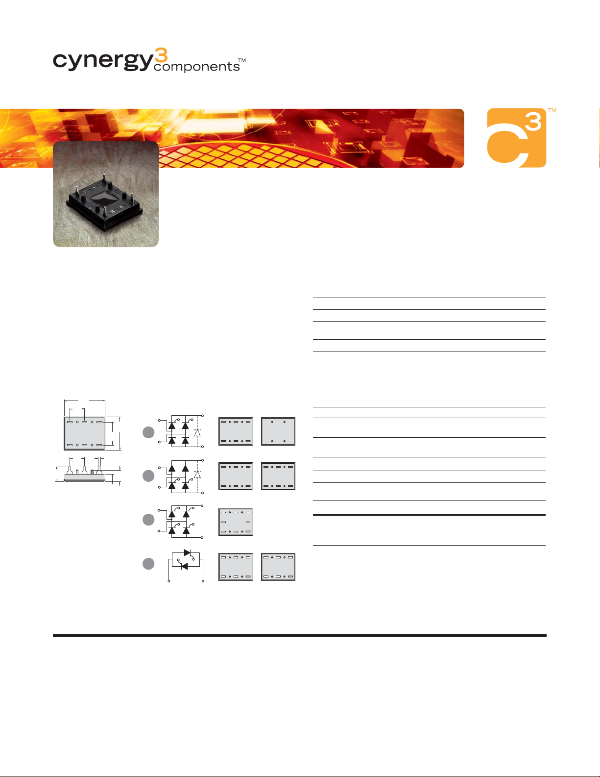
15-42.5Amp • SCR/Diode Modules
Circuit Modules provide ratings up to 42.5 amps in a low
profile package designed for printed circuit board connections.
Available in three standard bridge circuits and an AC switch
version, all models have 2500 Vrms isolation and are UL
recognized E72445. Mounting clip available, order part no. LMC-1.
Part Number Indentification
Series Current Circuit Type AC Line Voltage Options
L 3 - 15 Amps 1 - 5 1 - 120 Vac F - Free
5 - 25 Amps (see schematic 2 - 240 Vac Wheeling
6 - 42.5 Amps* diagrams) 3 - 280 Vac Diode
4 - 480 Vac (Circuits 1, 2)
Example:
L512F * 42.5 Amp Rating Not Available In Circuit 4
Mechanical Dimensions
All dimensions are in inches (millimeters)
1.38
(35.0)
.500
.500
(12.7)
(12.7)
.500
(12.7)
.78
(19.8)
.050 Typ.
(1.2)
.25
(6.3)
1.12
(28.4)
.39
(9.8)
AC1
G2
G1
1
AC2
AC1
2
AC2
AC1
4
AC2
5
G2
G1
G2G1
G4
G3
G1
G2
AC1
AC2
+
AC1
AC2
--
+
AC1
AC2
--
+
AC2
AC1
--
AC2
AC1
L3, L5 L6
G1
--
G2
+
G1
--
G2
+
G2
--
G1 G4
G3
+
G2
AC2
G1
AC1
#
Low Profile
#
Designed for PCB Connections
RATINGS
Electrical Specifications
L3 L5 L6
IDMaximum DC Output Current @ Tc = 85˚C (A) 15 25 42.5
VFMaximum Voltage Drop @ Amps Peak
2.2V @ 15A 1.65V @ 25A 1.6V @ 42.5A
TJOperating Junction Temperature Range -40˚C to +125˚C
di/dt Critical Rate of Rise of On-State
Current @ TJ=125˚C (A/µs)
100
dv/dt Critical Rate of Rise of Off-State Voltage 500
AC Line Input Voltage 240 (600 V
V
RMS
(Repetitive Peak Reverse Voltage) 280 (800 V
Maximum Non-Repetitive
I
TSM
Surge Current (A) [ 1/2Cycle, 60Hz]
225 300 600
120 (400 V
480 (1200 V
)
RRM
)
RRM
)
RRM
RRM
)
I2T Maximum I2T for Fusing (A2sec) [t=8.3ms] 210 375 1500
G2
G1
+
AC1
AC2
--
G1
AC1
--
G2
AC2
+
Maximum Required Gate Current
I
GT
to Trigger @ 25˚C (mA)
Maximum Required Gate
V
GT
Voltage to Trigger @ 25˚C (V)
P
Average Gate Power 0.5W
G(AV)
60 60 80
2.5 2.5 3.0
VGMMaximum Peak Gate Voltage (Reverse) 5.0V
Maximum Thermal Resistance Junction to
R
OJC
Ceramic Base per Chip
V
Isolation Voltage 2500 V
ISOL
1.25˚C/W 0.9˚C/W 0.7˚C/W
RMS
Mechanical Specifications
Weight (Typical) .5 oz. (14.4 g)
G2
AC2
AC2
G1
AC1
AC1
ISO9001 CERTIFIED
Approvals
UL - E72445
© 2006 Cynergy3 components, All Rights Reserved.
Competitive part number cross-reference available at:
USA
Sales & Tech Support
Email:
sales@cynergy3.com
(866) 258-5057
Cynergy3 Components
2320 Paseo de las Americas, Suite 104
San Diego, CA 92154
EUROPE - UK
Telephone
+44 (0) 1202 897969
Fax
+44 (0) 1202 891918
Email:
sales@cynergy3.com
Cynergy3 Components Ltd.
7 Cobham Road
Ferndown Industrial Estate
Wimborne, Dorset BH21 7PE
Specifications are subject to change without prior notice. Cynergy3 components and the Cynergy3 components logo are trademarks of Cynergy3 components Corp.
www.cynergy3.com
ASIA - Thailand
Telephone
Fax
+66 (0)2 665 2588
Cynergy 3 Components, Asia
18/8 Fico Place 12th Floor
Soi Sukhumvit 21 (Asoke)
Klongtoey Nua, Wattana
Bangkok, Thailand 10110
+66 (0)2 665 2517
 Loading...