

Cynergy3 UF Series Installation Instructions Manual
www.cynergy3.com
© 2014 Cynergy3 Components, All Rights Reserved. Specifications are subject to change without prior notice. Cynergy3 Components and the Cynergy3 Components logo are trademarks of Cynergy3 Components Limited.
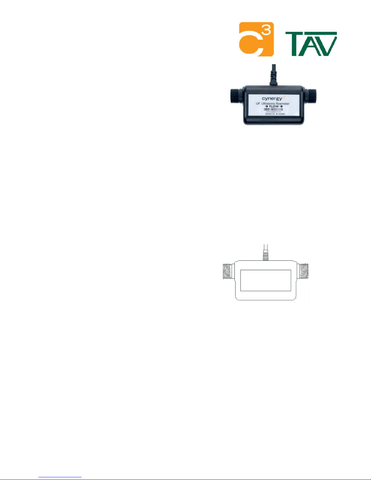
UF installation instructionsSeries
The pulse output versions are recommended for best performance.
The analogue 4-20mA versions must be connected to a measurement or display
instrumentation with a total load impedance less than100 ohms, including the wiring
between the meter and the user equipment.
Mechanical Installation
The may be installed at any angle, although it is recommended that it beunit
installed with the pipe entry and exit horizontal and the cable entry at the top, so
that the U-shaped measurement section remains full of liquid, should the process
empty of liquid.
3/8BSP plastic fitting must be used to connect to the UF25 to avoidunit
damaging the pipe connection threads. DO NOT OVERTIGHTEN. Max tightening
torque 3Nm.
Suitable John Guest pushfit connectors are PI451613S for the UF25 and PI0412S
for the UF08B100
The outer case is sealed to IP66
Electrical Installation
An eight core cable is used to connect to this unit. This should be connected as follows:
Supply: - Red: + (8 - 2 Vdc only), Black: common ground, Green: ground (internally connected to black).4
Selectable outputs:- Blue: NPN Pulse, White: PNP Pulse, Orange: Voltage 0-5Vdc, Brown: Current 4-20mA
Yellow wire should not be connected at all.
Applications information
Installation position
The unit should not be placed on the suction side of a pump,
always on the outlet side. The unit may be supported by
pipework of hoses due to its low weight, but should not be used
to support pipework or be subjected to vibration.
Liquids
The measuring tube is manufactured from a food grade plastic,
so is safe for use with drinking water and other beverages. Most
oils and other non-corrosive liquids can also be used. Liquid
and ambient temperatures must not be exceeded.
Pipe inlet diameter
A pipe diameter that matches the inlet on the unit is
recommended. Inlet bore diameters are 10mm on the UF25 and
7mm on the UF08.
Entrained gas/solids
This unit is designed to operate with clean liquids only. If
amounts of gas or solids increase beyond 1% by volume,
accuracy can be affected. Higher levels of gas or solids can
prevent transmission of the ultrasonic signal and the output will
fall to zero.
ISO
9001
CERTIFIED
Cynergy3 Components Ltd.
7 Cobham Road
Ferndown Industrial Estate
Wimborne, Dorset BH21 7PE
Telephone +44 (0) 1202 897969
Email:sales@cynergy3.com
Please see connection circuits overleaf

Connecting a 4-20mA Output device
4-20mA Standard
4-20mA output systems are an industrial control standard as they allow input signal changes, without affecting the output current. This also
means that the output signal is relatively immune to noise (as most noise will cause voltage disturbances, and not affect the regulated
current). This makes 4-20mA devices more suited to critical-control systems.
Cable Connection Red: Power Supply +ve connection Black: Common : Current Sink (4-20mA)s - , , Brown
Excessive Load Resistance will cause current sourcing that will affect the accuracy of this device's current output.
Maximum Load Impedance: ( 5) x 40
RL= Vin -
Note: There is no requirement for a minimum Load resistance, as this is a current sink device
An ammeter (or suitably arranged multi-meter), placed in series at the Iout point, will give an indication of the sensors current performance i.e.
flow.
If the meter used has adjustable zero and span, then the meter could be altered to represent the flow in litres/min.
Iout
4-20mA
UF
Sensor
Supply +V
(8-24Vdc)
Brown
Current Sink
Red +V
Power Supply
I
Black
Common
R
Load(circuit)
Connecting an Open Collector Pulse Output device
The term typically refers to a transistor output where the collector (output) of the transistor is not connected to a positiveopen-collector
voltage. Since a transistor used in outputs is a saturated switch, the collector needs to be connected to a positive voltage to complete the
transistor circuit. This positive voltage need not be any specific value as long as it is above the saturation of the transistor. Because of this, an
open collector output can be connected to a range of voltages using a pullup resistor. This resistor is required for the output to function as it
completes the transistor's circuit.
Many circuits use open-collector outputs to be able to provide Different Voltage Interfacing
Since the exact voltage of the pullup resistor is not critical, an open-collector output can be used to interface one logic voltage level with
another.
UFunit
UFunit
Counter
Counter
10kR
10kR
Supply +V2
5-2 Vdc4
Supply +V
8-2 Vdc4
Supply +V1
8-2 Vdc4
Red
Red
Blue
Blue
Black
Black
Circuit using different voltages
Circuit using common voltage supply
www.cynergy3.com
© 2014 Cynergy3 Components, All Rights Reserved. Specifications are subject to change without prior notice. Cynergy3 Components and the Cynergy3 Components logo are trademarks of Cynergy3 Components Limited.
ISO
9001
CERTIFIED
 Loading...