

Page 1
SAFETY PRECAUTIONS
This radio control model is not a toy!
lFirst-time builders should seek advice from people having building
experience in order to assemble the model correctly and to produce
its performance to full extent.
,
lAssemble this kit only in places out of childrens reach!
lTake enough safety precautions prior to operating this model.
,
You are responsible for this models assembly and safe operation!
lAlways keep this instruction manual ready at hand for quick
reference,even after completing the assembly.
lCould cause serious injury or even death
SPECIFICA TION
Wing Span:3000mm (118.1in)
2
Wing Area:102.9dm(1 549.6sq.in)
Total Length: 1970 mm (77.6 in)
Engine :80-100cc gas engine
Radio : 5channels ,9 servos(landplane)
6channels ,11servos(floatplane)
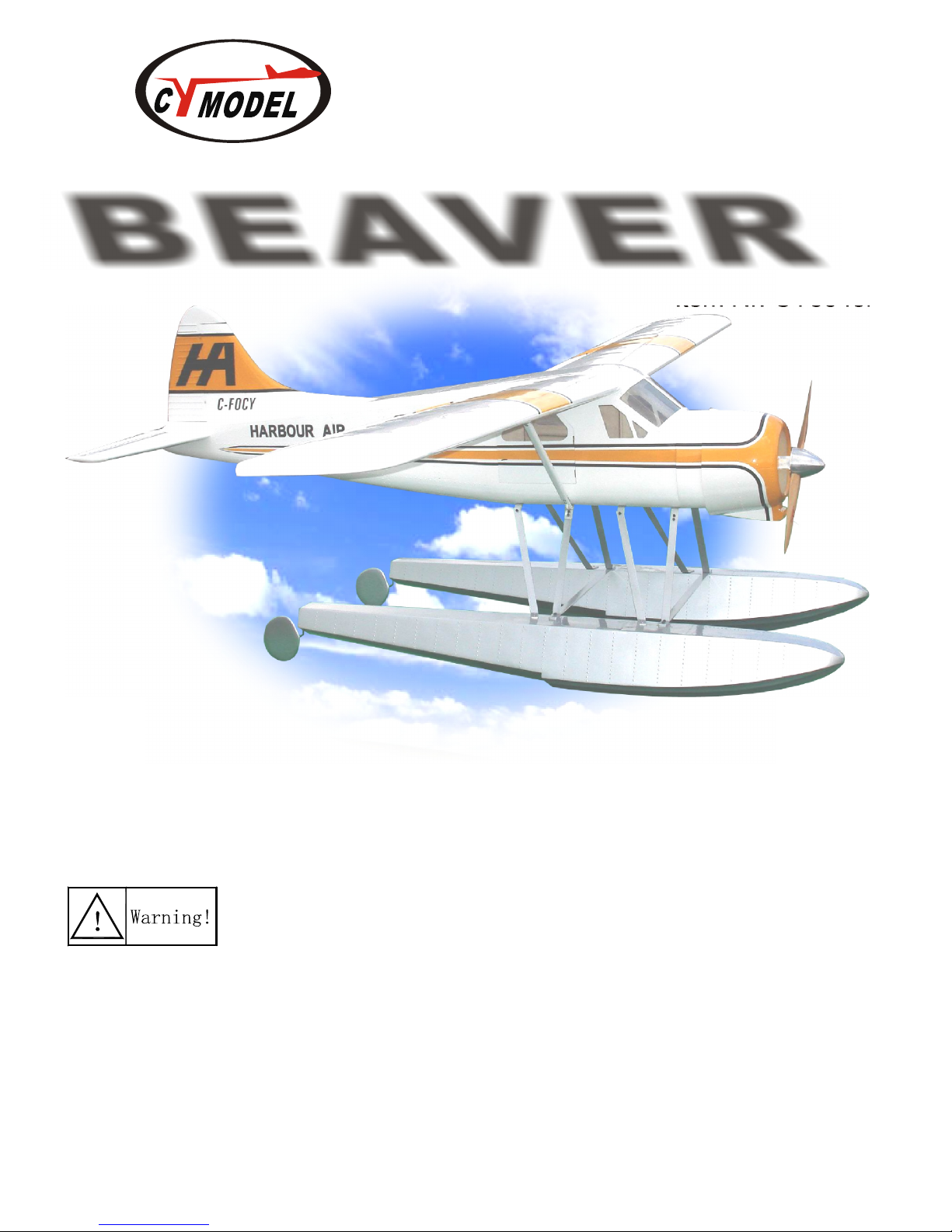
BEAVER
ALMOST - READY - TO - FLYALMOST - READY - TO - FLY
Before commencing assembly,please read these instructions thoroughly.
Thank you for choosing CYmodel
Global : www.cymodel.com
Australia : www.austars-model.com
Italia : www.biellaexpress.com
Instruction Manual
Item Nr: CY8043B
Page 2
22
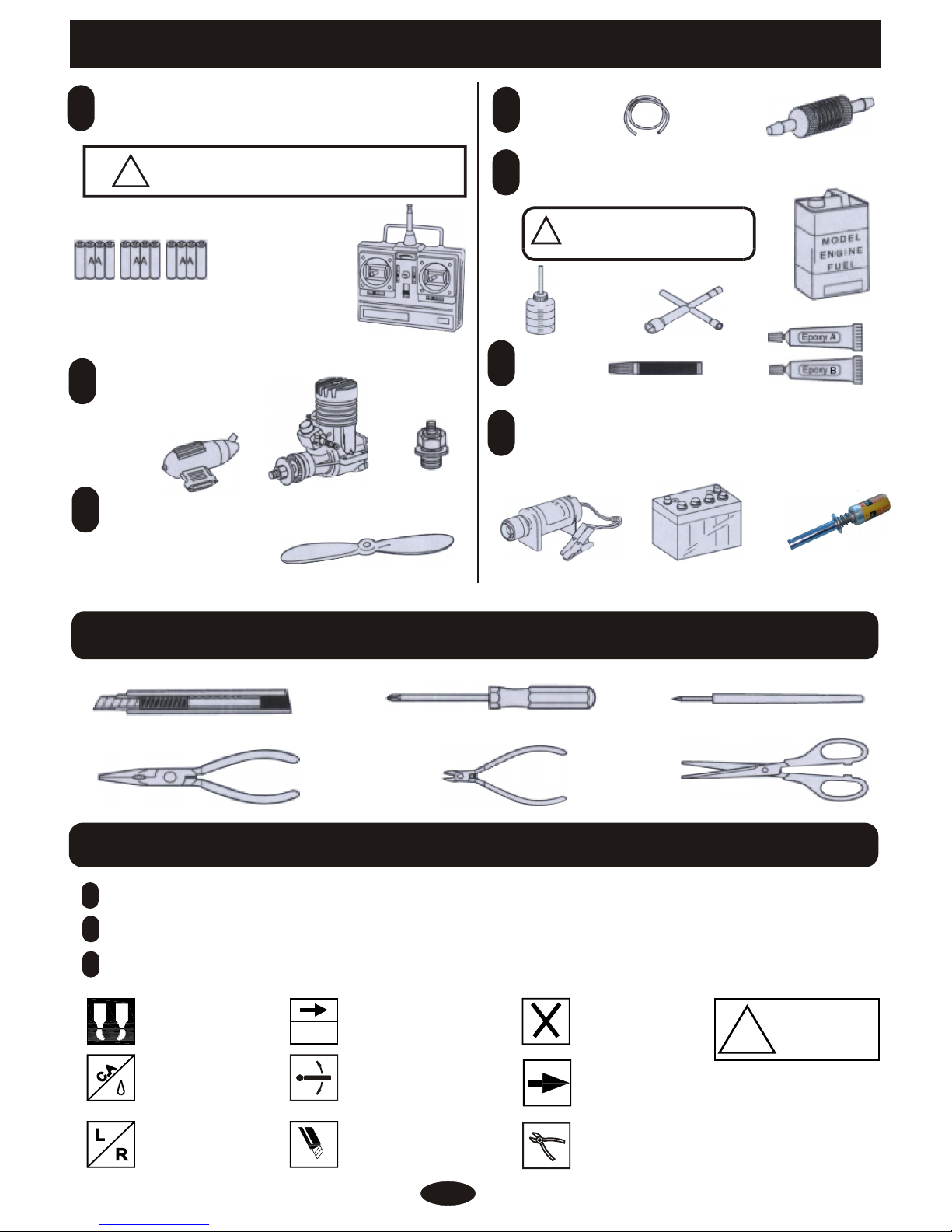
REQUIRED FOR OPERATION (Purchase separately) REQUIRED FOR OPERATION (Purchase separately)
TOOLS REQUIRED ( Purchase separately)TOOLS REQUIRED ( Purchase separately)
BEFORE YOU BEGINBEFORE YOU BEGIN
Sharp Hobby Knife
Phillips Screw Driver
Awl
Needle Nose Pliers
Wire Cutters
Scissors
Read through the manual before you begin ,so you will have an overall idea of what to do.
Check all parts .if you find any defective or missing parts .contact your local dealer.
Symbols used throughout this instruction manual,comprise.
11
22
33
.
.
.
Warning!
£¡
Cut off shaded portion.
Ensure smooth non-binding
movement while assembling.
Must be purchased
separately!
Pay close attention
here!
Drill holes with the specified
Diameter(here:2mm)
2mm
Assemble left and right
Sides the same way.
Apply instant glue
(CA glue,super glue).
Apply epoxy glue.
BA
Cut off excess.
!
Do not overlook this symbol.
11
A minimum 5channel radio for airplanes (with 9servos).
And dry batteries.
CAUTION: Only use a minimum 5channel radio for
airplanes! (No other radio may be used!)
!
12 AA-size Batteries
A minimum 5 channel
transmitter for airplanes.
22
For handing the radio properly.refer to its instruction manual.
Engine and Muffler
Muffler
Glow plug
33
Purchase a propeller that
will match your engine
44
Silicone Tube
Fuel Filter
55
Required for engine starting
Glow engine fuel only.
WARNING: Normal gasoline cannot
be used with glow engines.
!
Fuel Pump
Plug Wrench
33
Glue
66
Instant glue
Epoxy Glue
33
Other equipment for enhancing
airplane operation & perormance
77
12V Battery (for starter)
Engine Starter
Propeller splinner
MA
odel irplane engine
Ignition
80-100cc gas engine
Page 3
!
3
2
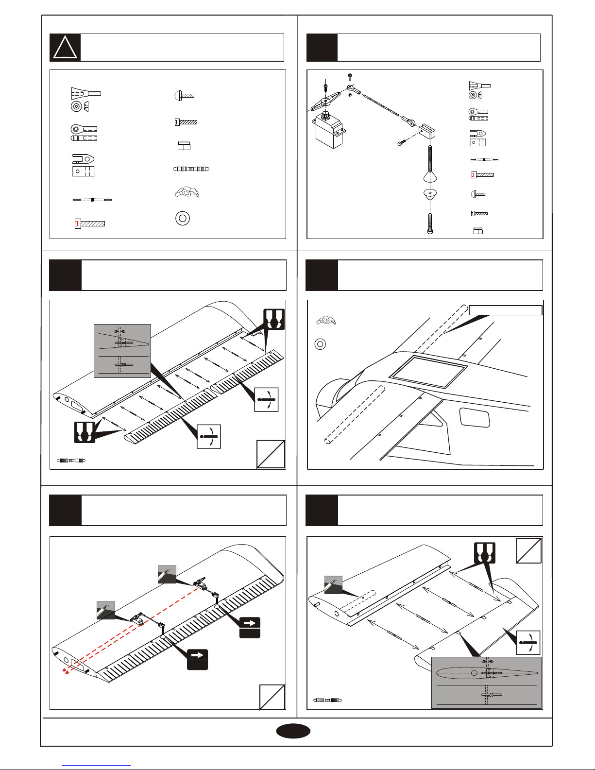
Install the aileron and flap
1
5
4
33
Main wing
Hinge
- - - - - - 18
Install the servo of aileron and flap
Top view
Bottom view
Install the elevator
Install the servo of aileron and flap
Servo line
25X1195mm tube
Bottom view
Hinge
- - - - - - 8
Hinge
Accessory list for this page.
L
R
L
R
The servo must be purchase separatelyThe servo must be purchase separately
L
R
Horn
Rod adjuster
Connecting rod head
2.5X85mm rod
4X35mm screw
3X10mm Screw
3X14mm Screw
3mm Lock nut
- - - - - - 4
- - - - - - 4
- - - - - - 8
- - - - - - 4
- - - - - - 4
- - - - - - 4
- - - - - - 4
- - - - - - 4
- - - - - - 4
55
8mm washer
- - - - - - 4
8mm nylon Nut
- - - - - - 4
55
4mm4mm
4mm4mm
A B
A B
A B
Horn
Rod adjuster
Connecting rod head
2.5X85mm rod
4X35mm screw
3X10mm Screw
3X14mm Screw
3mm Lock nut
- - - - - - 4
- - - - - - 4
- - - - - - 8
- - - - - - 4
- - - - - - 4
- - - - - - 4
- - - - - - 4
- - - - - - 4
- - - - - - 4
8mm washer
- - - - - - 4
8mm nylon Nut
- - - - - - 4
- - - - - - 26
Page 4
!
8
7
10
99
44
6
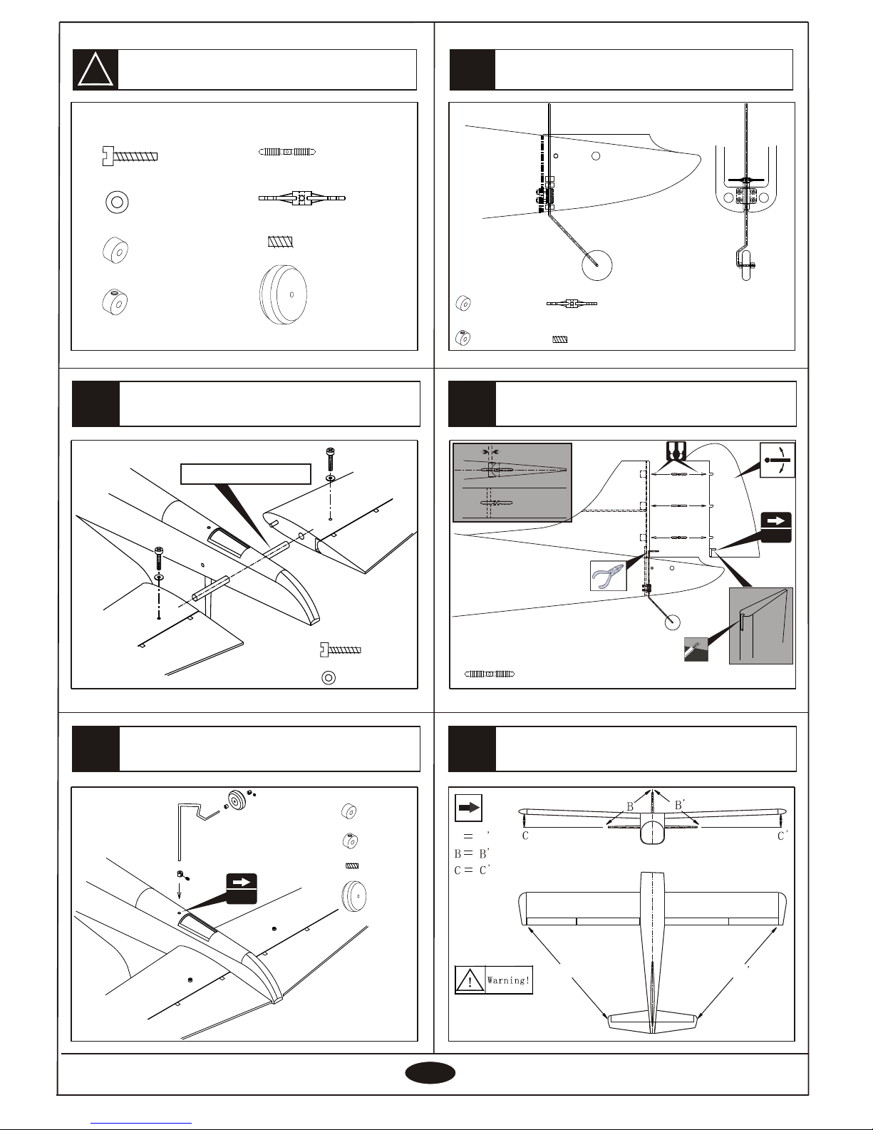
Accessory list for this page.
Install the elevator
4X20mm Screw
- - - - - - 2
4mm washer
- - - - - - 2
12.5X325mm tube
Install the tail wheel
Install the rudder
Hinge
- - - - - - 3
55
Diameter
3mm3mm
3.2mm Nylon Collar
3.2mm Collar
3X3mm Screw
- - - - - - 2
- - - - - - 1
- - - - - - 2
45mm wheel
- - - - - - 1
3.2mm Nylon Collar
3.2mm Collar
3X3mm Screw
- - - - - - 1
- - - - - - 1
- - - - - - 2
Install the tail wheel
3.2mm Rocker
- - - 1
Horizontal/Vertical tail
Securely glue together
,if coming off during flights.
You lose control of your airplane
which leads to accidents!
AA
A
A
3mm3mm
A B
4X20mm Screw
- - - - - - 2
4mm washer
- - - - - - 2
3.2mm Nylon Collar
3.2mm Collar
3X3mm Screw
- - - - - - 3
- - - - - - 2
- - - - - - 4
3.2mm Rocker
- - - 1
Hinge
45mm wheel
- - - - - - 1
- - - - - - 3
Page 5
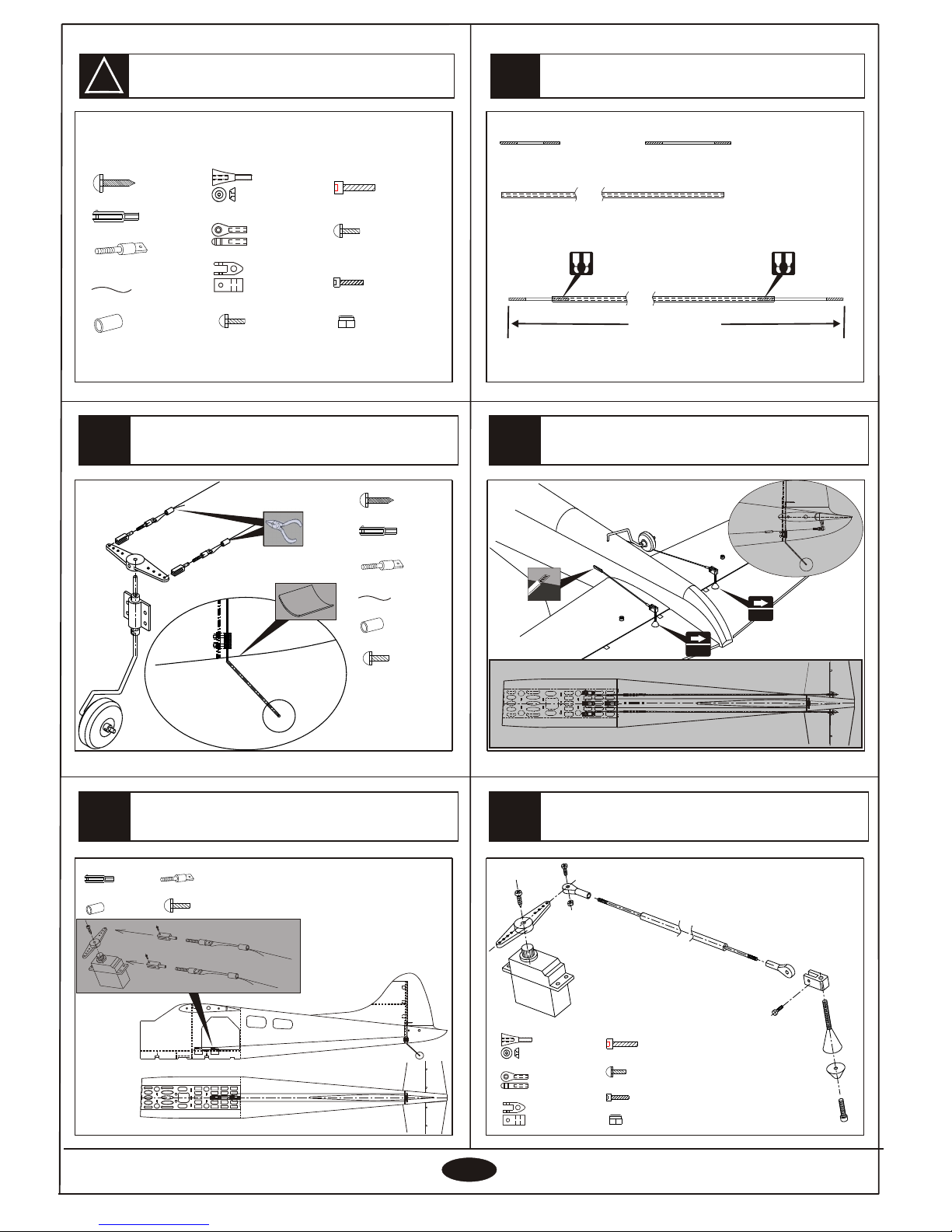
!
13
12
15
14
11
55
Accessory list for this page.
Install the rod of elevator
Rod
2X8mm screw
- - - - 2
- - - - 2
Rod adjuster
- - - - 2
Aluminium tube
- - - - 2
1500mm Steel wire
- - - - 2
2.3X10mm Tp screw
- - - - - - 4
The cover
Install the servo of rudder and tail wheel
Install the servo of rudder and tail wheel
Rod
2X8mm screw
- - - - 2
- - - - 2
Rod adjuster
- - - - 2
Aluminium tube
- - - - 2
The servo must
be purchase
separately
The servo must
be purchase
separately
Install the servo of elevator
Horn
Rod adjuster
Connecting rod head
4X35mm screw
3X10mm Screw
3X14mm Screw
3mm Lock nut
- - - - - - 2
- - - - - - 2
- - - - - - 4
- - - - - - 2
- - - - - - 2
- - - - - - 2
- - - - - - 2
- - - - - - 2
1187mm
2.5X100 rod 2.5X310 rod
5X3X870 carbon rod
- - - - - 2
- - - - - 2
- - - - - 2
Install the servo of elevator
The servo must be
purchase separately
The servo must be
purchase separately
4mm4mm
4mm4mm
A B A B
Rod
2X8mm screw
- - - - 4
- - - - 4
Rod adjuster
- - - - 4
Aluminium tube
- - - - 4
1500mm Steel wire
- - - - 2
2.3X10mm Tp screw
- - - - - - 4
Horn
Rod adjuster
Connecting rod head
4X35mm screw
3X10mm Screw
3X14mm Screw
3mm Lock nut
- - - - - - 2
- - - - - - 2
- - - - - - 4
- - - - - - 2
- - - - - - 2
- - - - - - 2
- - - - - - 2
- - - - - - 2
Page 6
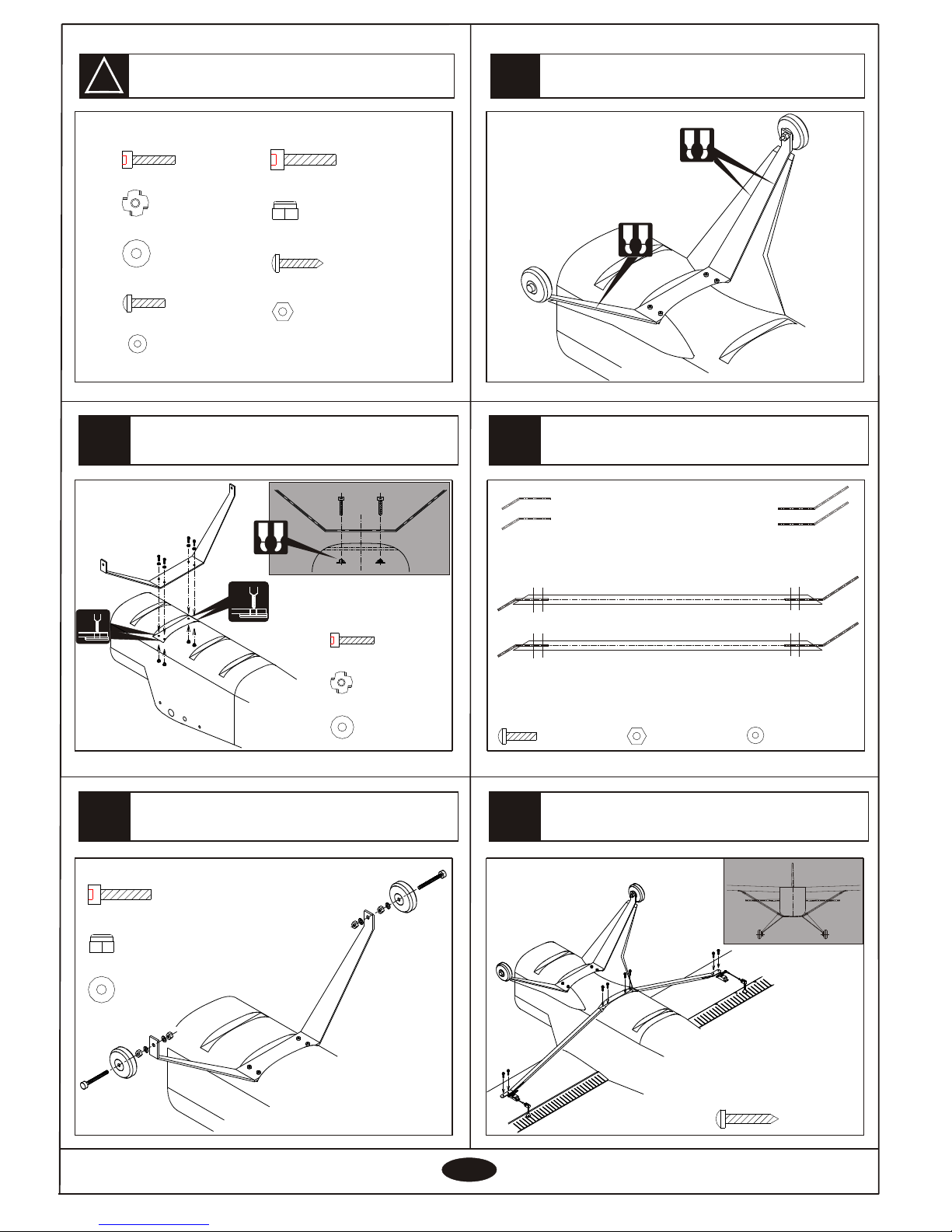
!
18
17
20
19
66
16
Accessory list for this page.
Install the main landing gear
Engine:100cc gasEngine:100cc gas
Diameter
5X25mm screw
5mm Bind nut
5mm Washer
- - - - - - - - 4
- - - - - - - - 4
- - - - 4
Install the engine
5X55mm screw
5mm Lock nut
5mm Washer
- - - - - - - - 4
- - - - - - - - 4
- - - - 2
Install the main landing gear
5.2mm5.2mm
5.2mm5.2mm
A B
A B
Install the wing support
A B
Install the wing support
3X20mm screw
3mm nut
3mm Washer
- - - - - - - - 16
- - - - - - - - 8
- - - - - - - - 8
Aluminum plank
Aluminum plank
Wood support
3X20mm Tp screw
- - - - - - - 8
5X25mm screw
5mm Bind nut
5mm Washer
- - - - - - - - 8
- - - - - - - - 4
- - - - 4
5X55mm screw
5mm Lock nut
- - - - - - - - 4
- - - - 2
3X20mm screw
3mm nut
3mm Washer
- - - - - - - - 16
- - - - - - - - 8
- - - - - - - - 8
3X20mm Tp screw
- - - - - - - 8
Page 7
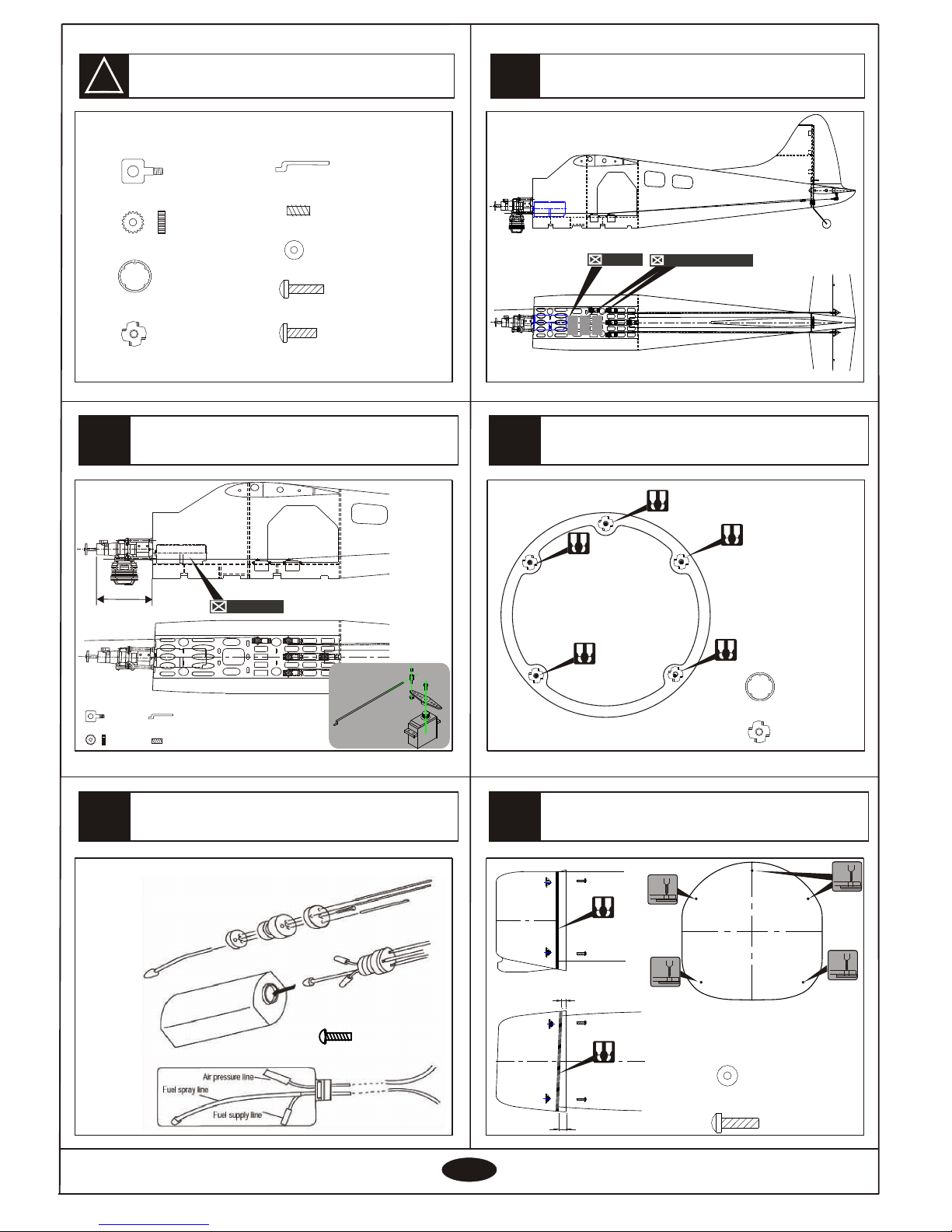
!
23
22
25
24
77
21
Accessory list for this page.
Install the engine
3X20mm Screw
- - - - 1 - - - - 1
Assembly of the full tank
Install the cowling
1.8X450mm Rod
- - - - - - 1
Linkage Stopper
2mm Nut
- - - - 1 - - - - 1
- - - - 1
3X3mm Screw
- - - - - - 1
160mm
Fuel tankFuel tank
Engine :80-100cc gas
Radio Equipment
Install the cowling
BatteryBattery
Receiver/BatteryReceiver/Battery
3mm Bind nut
- - - - - - - - 5
6mm Plywood
- - - - - - - - 1
A B
A B
A B
A B
A B
3.2mm
A B
A B
10.5mm
20mm
3.2mm
3X25mm screw
3mm Washer
- - - - - - - - 5
- - - - - - - - 5
1.8X450mm Rod
- - - - - - 1
Linkage Stopper
2mm Nut
- - - - 1
- - - - 1
3X3mm Screw
- - - - - - 1
3mm Bind nut
- - - - - - - - 5
6mm Plywood
- - - - - - - - 1
3X25mm screw
3mm Washer
3X20mm Screw
- - - - - - 5
- - - - - - 1
- - - - - - 5
After confirming the
position(see front of
fuel tank).
Insert and tighten
the screw.
3.2mm
3.2mm
Page 8
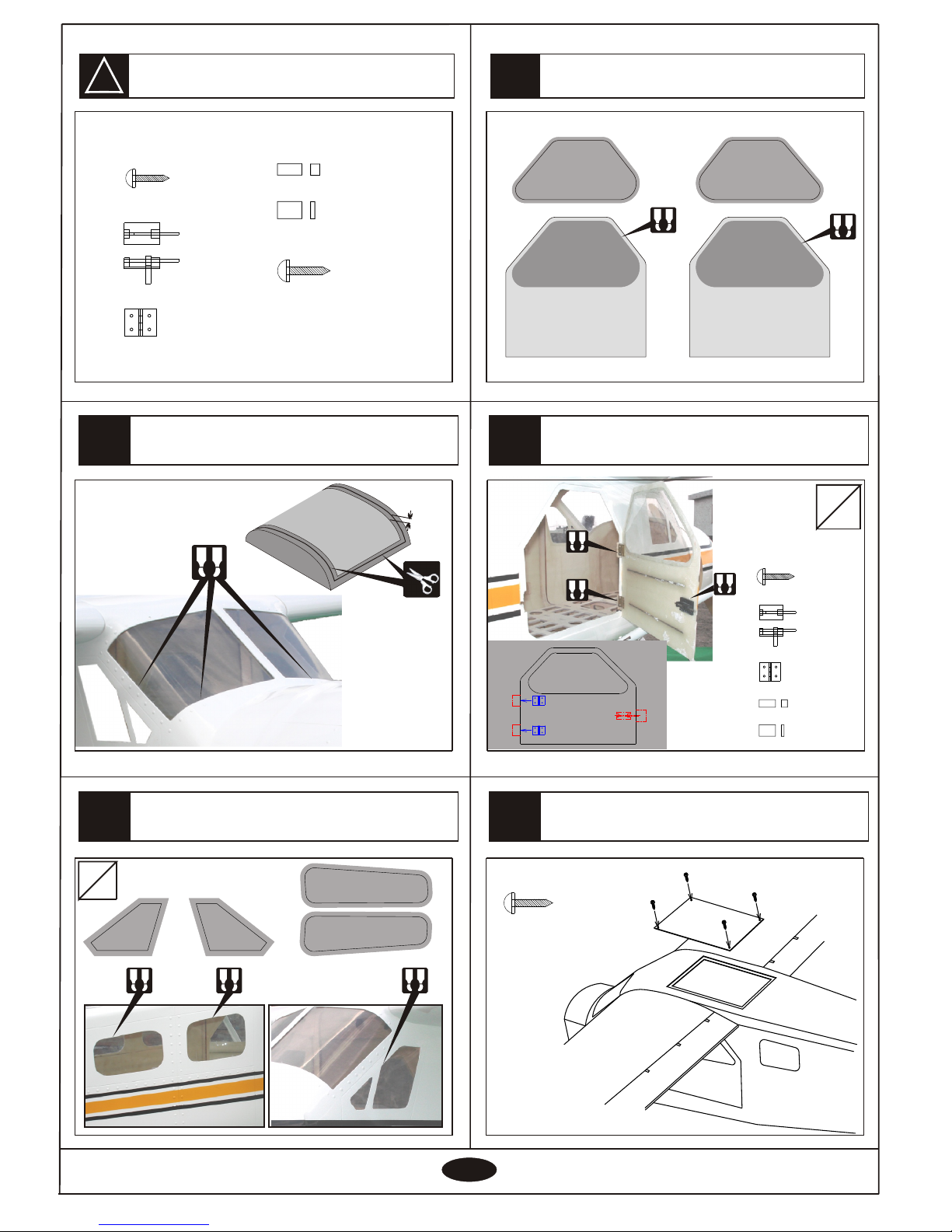
!
28
27
30
29
88
26
Accessory list for this page.
Install the canopy
Cut away the surplus pats of canopy
care fully along the shaded line,
Outside the line 8mm
A B
8mm
A B A B A B
A B
A B
A B
L
R
A B
A B
Fasten
Loose-leaf
Hard wood
Balsa
- - - - - 2
- - - - - 4
- - - - - 4
- - - - - 2
Hard wood
Hard wood
Balsa
Loose-leaf
Fasten
Loose-leaf
2.3X8mm Tp screw
- - - - - - 8
Fasten
Loose-leaf
Hard wood
Balsa
- - - - - 2
- - - - - 4
- - - - - 4
- - - - - 2
2.3X8mm Tp screw
- - - - - - 8
Install the windows
Install the door and windows
2.3X10mm Tp screw
- - - - - - 4
Install the coverInstall the cover
Install the door and windows
2.3X10mm Tp screw
- - - - - - 4
L
R
Page 9
!
33
32
35
34
99
31
Accessory list for this page.
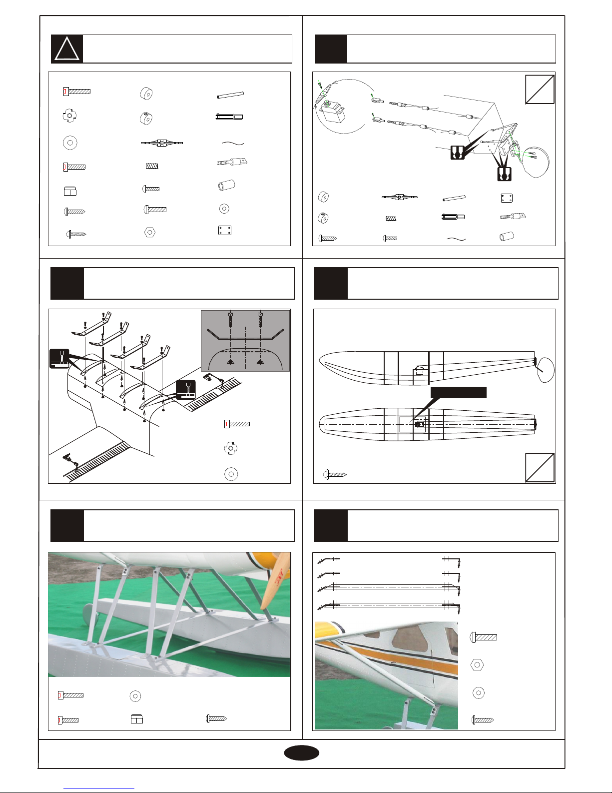
Install the float
you should install the float to fly
the plane on water.
Install the servo of float
The wing support's install method
while installing float.
Diameter
4X25mm screw
4mm Bind nut
4mm Washer
- - - - - - - - 8
- - - - - - - - 8
- - - - 8
4.2mm4.2mm
Install the float
4.2mm4.2mm
4X25mm screw
4mm Washer
- - - - - - - - 8
- - - - 8
4X16mm screw
- - - - 12
3X20mm screw
3mm nut
3mm Washer
- - - - - - - - 16
- - - - - - - - 8
- - - - - - - - 8
4mm Lock nut
- - - - - - - - 12
3X20mm Tp screw
- - - - - - - 8
3X20mm Tp screw
- - - - - - - - 4
2.3X10mm Tp screw
- - - - 8
L
R
L
R
The coverThe cover
3X20mm Tp screw
3.2mm Nylon Collar
3.2mm Collar
3X3mm Screw
- - - - - - 2
- - - - - - 2
- - - - - - 4
3.2mm Rocker
- - - 2
- - - - - - 8
Rod
2X8mm screw
- - - - 4
Rod adjuster
- - - - 4
Aluminium tube
- - - - 8
1800mm Steel wire
- - - - 4
- - - - - - 4
3.5X50 mm Pvc tube
- - - - 4
3X20mm screw
3mm nut
3mm Washer
- - - - - - - - 16
- - - - - - - - 8
3.2mm Nylon Collar
3.2mm Collar
3X3mm Screw
- - - - - - 2
- - - - - - 2
- - - - - - 4
3.2mm Rocker
- - - 2
Rod
2X8mm screw
- - - - 4
Rod adjuster
- - - - 4
Aluminium tube
- - - - 8
1800mm Steel wire
- - - - 4
- - - - - - 4
3.5X50 mm Pvc tube
- - - - 4
4mm Bind nut
4mm Washer
- - - - - - - - 16
- - - - - - - - 8
4X25mm screw
- - - - 16
4X16mm screw
- - - - 12
4mm Lock nut
3X20mm Tp screw
- - - - - - - 20
2.3X10mm Tp screw
- - - - 8
- - - - - - - - 12
- - - - - - - - 8
A B
9mm plywood
- - - - 2
9mm plywood
- - - - - - - - 2
A B
Page 10
38
37
39
Side view
ELEV A TOR
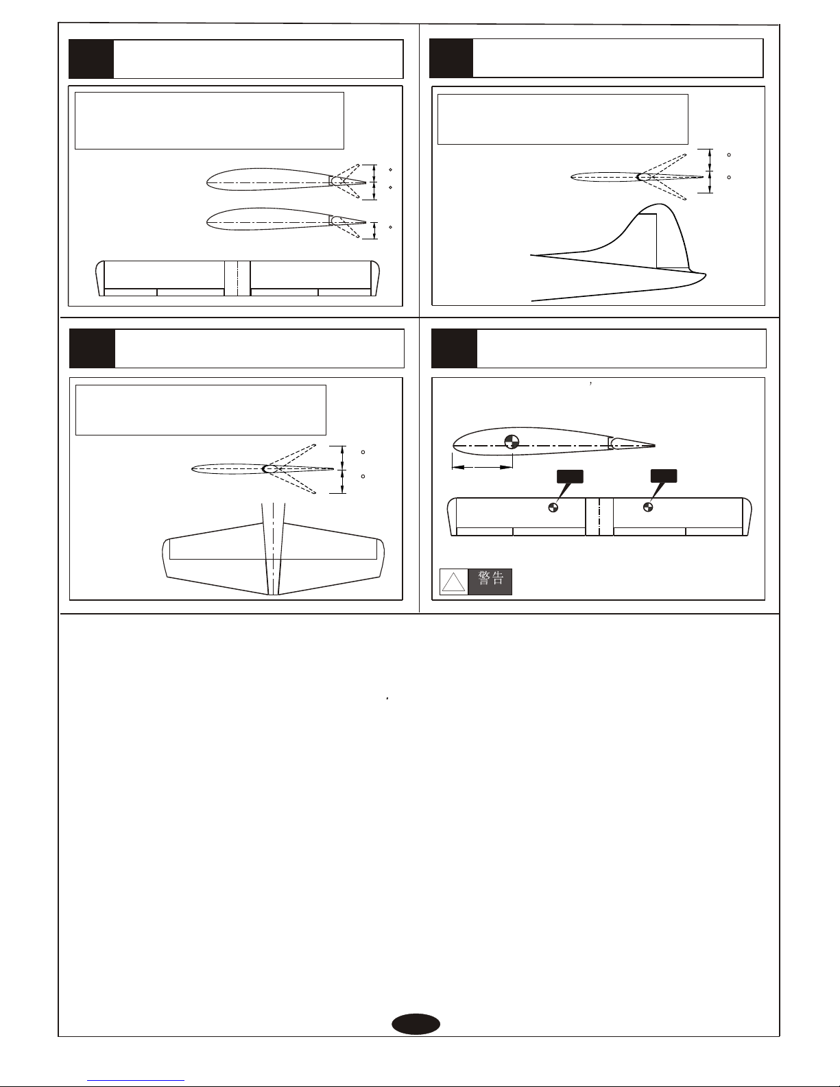
Adjust the travel of each control surface to the
values in the diagrams.
These values fit general flight capabilities.
Readjust according to your needs and flight level.
Top view
36
AILERON
Adjustment.
Top view
Adjust the travel of each control surface to the
values in the diagrams.
These values fit general flight capabilities.
Readjust according to your needs and flight level.
1010
Adjustment.
Never fly before checking the Cg s required position.
In order to obtain th e CG specified ,reposition the
receiver and battery.
NEVER fly the model
without well balancing.
Warning!
!
CGCG
Side view
Rudder
Adjust the travel of each control surface to the
values in the diagrams.
These values fit general flight capabilities.
Readjust according to your needs and flight level.
Top view
100-1 10mm100-110mm
Adjustment
Side view
Adjustment.
Aileron
Flap
CGCG
45
45
45
45
45
45
45
 Loading...