

Cylon CBX series, FLX-4R4-H, FLX-8R8, CBX-8R8, FLX-8R8-H Technical Datasheet And Installation Manual
...
DS0119 rev 40 ©2018 Cylon All Rights Reserved. Subject to change without notice
WWW.CYLON.COM
WWW.CYLON-AUTOMATRIX.COM
page 1 of
14
TECHNICAL DATASHEET & INSTALLATION GUIDE
CBX System
CBX System
CBX-8R8|CBX-8R8-H|FLX-4R4|FLX-4R4-H|FLX-8R8|FLX-8R8-H|FLX-16DI
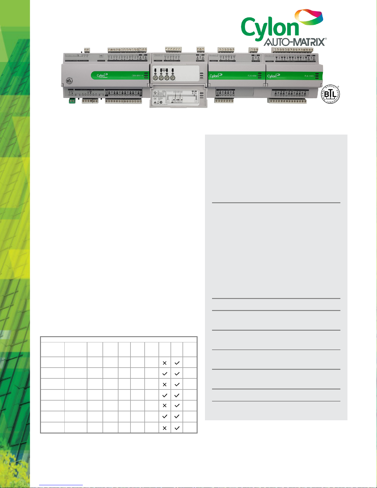
DESCRIPTION
The CBX-8R8(-H) is a fully programmable BTL-listed BACnet®
Advanced Application Controller (B-AAC) that communicates on
an RS-485 local area network using the BACnet® MS/TP protocol.
This controller features 8 UniPuts™ with Relay and 8 Universal
Inputs as well as support for up to three FLX (Field Level
eXpansion) series extension modules providing up to 64 points
of control. FLX expansion modules are available in a variety of
options to allow maximum flexibility in achieving the required
point configuration.
The CBX-8R8(-H) is designed for a wide range of applications for
intelligent control of HVAC equipment, lighting control, and
electrical systems including metering applications.
APPLICATION
The CBX-8R8(-H) is suitable for controlling various equipment
such as; air handling units, boilers, chillers, cooling towers, pump
systems, central plant equipment, variable frequency drives,
lighting control and metering. The controller supports multi-
protocol communications simultaneously including BACnet®
MS/TP and Modbus® RTU.
The fully programmable CBX-8R8(-H) can be tailored to meet a
variety of applications by creating and modifying strategies using
Cylon's CXpro
HD
programming interface.
Product Selection Chart
Part Number
Module
Service
UniPutsTM
with Rel ay1
Universal
Inputs
Digital
Inputs
Modbus
RTU
Devices
CBT-STAT
Bus
HOA
Switch
& Pot.
18 V
Aux
Power
FLX
I/O
Modules
CBX-8R8
Main
Controller
8 8 0 4* 1
3
CBX-8R8-H
Main
Controller
8 8 0 4* 1
3
FLX-4R4
Expansion
Module
4 4 0 0 0
-
FLX-4R4-H
Expansion
Module
4 4 0 0 0
-
FLX-8R8
Expansion
Module
8 8 0 0 0
-
FLX-8R8-H
Expansion
Module
8 8 0 0 0
-
FLX-16DI
Expansion
Module
0 0 16 0 0
-
Note: 1 – UniPutsTM are software configurable for point types AI, DI, AO or DO-R.
Note: * – CBX Modbus® RTU supports a total of 40 points across 4 devices
CBX-8R8
8 UniPuts™ + Relays
hardware connections that can be used as
inputs, outputs or relays (software selectable)
8 Universal Inputs
CBX-8R8-H
Including Hand/Off/Auto Local Override
Function
Field Level eXpansion Modules
FLX-4R4
4 UniPuts™ with Relay
4 Universal Inputs
FLX-8R8
8 UniPuts™ with Relay
8 Universal Inputs
FLX-16DI
16 Digital Inputs
FLX-4R4-H, FLX-8R8-H
Including Hand/Off/Auto Local Override
Function
Support for Cylon smart thermostat bus
LED status on all I/O channels provides
indication of fault or override status
Compact form factor to maximize enclosure
space
Scalable from 16 points to 64 points using FLX
modules
Easy module expansion using simple bus
connectors
Up to 64 Trendlogs, 1024 entries per Trendlog
Accurate Universal Inputs support a variety of
thermistors and RTDs that range from 0 to 450 kΩ
INSTALLATION GUID E : see page 5
DS0119 rev 40 ©2018 Cylon All Rights Reserved. Subject to change without notice
WWW.CYLON.COM
WWW.CYLON-AUTOMATRIX.COM
page 2 of
14
CBX System
TECHNICAL DATASHEET & INSTALLATION GUIDE
SPECIFICATIONS
MECHANICAL
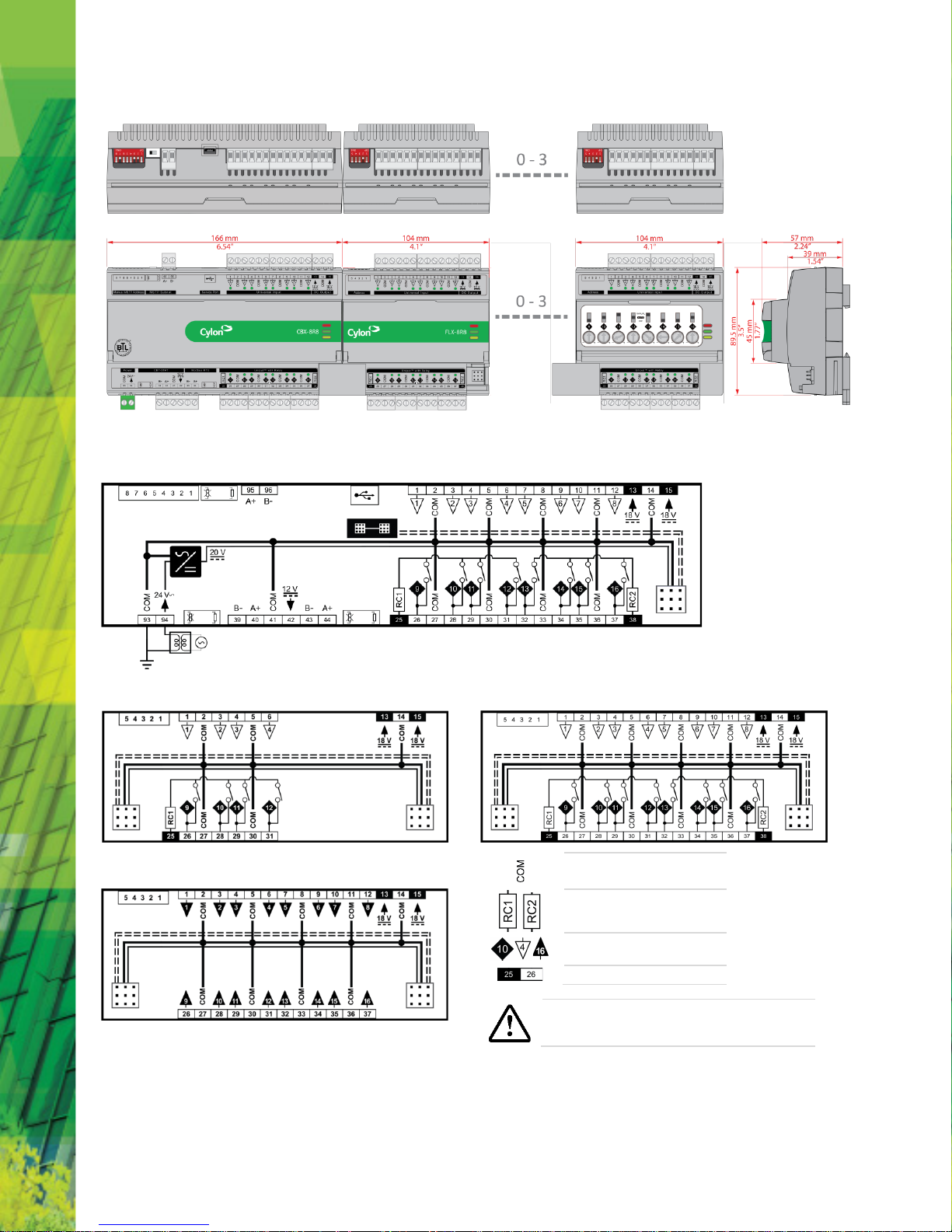
Size
(excluding terminal plugs)
CBX-8R8
CBX-8R8-H
166 x 89.5 x 57 mm [6.5 x 3.55 x 2.25”]
FLX-4R4
FLX-4R4-H
FLX-8R8
FLX-8R8-H
FLX-16DI
104 x 89.5 x 57 mm [4.1 x 3.55 x 2.25”]
Enclosure
Flame-Retardant ABS
DIN 43880 type-2 compatible
Mounting
DIN rail
CONNECTION
Note: Use Copper or Copper Clad Aluminum 70 °C conductors only.
Terminals
PCB mounted plug terminal connections
Conductor Area
Max: AWG 12 (3.31 mm2)
Min: AWG 22 (0.355 mm
2
)
ENVIRONMENT
Note: This equipment is intended for field instal lation within an enclosure.
Ambient Temperature
-25 °C … 50 °C (-13 °F … 122 °F)
Ambient Humidity
0% … 90% RH non-condensing
Storage Temperature
-30 °C … +70 °C (-22 °F … 158 °F)
EMC Immunity
EN 61326-1: 2013
EMC Emission
EN 61326-1: 2013
EN 61000-3-2: 2014
EN 61000-3-3: 2013
Approvals
UL Listed (CDN & US) UL916 Energy Management
Equipment – File No. E176435
ELECTRICAL
Supply Requirements
24 V AC ±20 % 50/60 Hz
Supply
Rating
CBX
50 VA (no FLX modules)
CBX + 1 x FLX
66 VA
CBX + 2 x FLX
82 VA
CBX + 3 x FLX
98 VA
FLX Power
Connection Proprietary FLX bus connector carries power and
comms from CBX-8R8(-H) unit. CBX-8R8(-H) can
supply power to up to 3 FLX modules.
Auxiliary
Power 18 V DC / 60 mA output
BACnet® Loading
¼ unit load device
PROCESSOR
Type
STM32 ARM Cortex-M3 proce ssor
Clock Speed
8 MHz crystal, 72 MHz internal processor clock rate
System Memory
1MByte external SRAM + 16 Mbyte external flash
(soldered to PCB not removable)
Real
-Time Clock Battery backed for 2 years minimum
COMMUNICATIONS
Local serial port
USB Micro-B socket (used as service port)
BACnet
® MS/TP port RS485 @ 9K6,19K2, 38K4, 57K6, 76K8 or 115k2
Baud
(defaults to 38K4). Max cable length 1.2 km
Modbus Port
Support for Modbus RTU
(4 Modbus devices or 40 points)
CBT-STAT Port
RS485 with a maximum cable length 500 m
FLX bus
115.2K Baud
Max bus length (including e xtension cables):
30 m / 10 0 ft. using 1 8 AWG conductors
15 m / 50 ft. using 22 AWG conduct ors
FLX bus Connection
FLX bus connector carries inter-module
communications and module power
INPUTS / OUTPUTS
Note: Shielded cable i s recommended for al l input connections.
UniPuts™ with Relay
When configured as Input:
Analog Input
Range: 0 ... 10 V @ 40 kΩ
Accuracy: ±0.5% full scale [50mV]
Resistance measurement
Range: 0 ... 450 kΩ
Accuracy: ±0.5% of measured resistance
Temperature measurement
Range: -40 °C ... +110 °C
Accuracy: 10k NTC sensors (e.g. 10k Type 2 ( 10K3A1) or
10k Type 3 (10K4A1) : ±0.3 °C, -40 to 90 °C (40°F to 194°F); ±0. 4 °C > 90 °C (194°F)
Current input
Range: 0 ... 20 mA @ 390 Ω
Note: Curre nt Input re quires user-supplied external
390 Ω resistanc e.
Accuracy: depends on user supplied external resistor
Digital Volt-Free contact, 2 mA contact-wettin g current
Pulse counting up to 20 Hz, 25 ms - 25 ms
When configured as
Output:
Analog Output 0 ... 10 V, 20 mA, 12-bit resolution
Digital Output 0 ... 10 V, 20 mA
Relay Contacts with ability to switch up to 24 V AC
Maximum Load: 24 V AC, 2 (1) A resistive (inductive)
for all relay contacts
Universal Inputs
Analog Input
Range: 0 ... 10 V @ 130 kΩ
Accuracy: ±0.5% full scale [50mV]
Resistance measurement
Range: 0 ... 450 kΩ
Accuracy: ±0.5% of measured resistance
Temperature measurement
Range: -40 °C ... +110 °C
Accuracy: 10k NTC sensors (e.g. 10k Type 2 ( 10K3A1) or
10k Type 3 (10K4A1) : ±0.3°C, -40 to 90°C (-40°F
to 194°F); ±0.4°C > 90°C (194°F)
Current input
Range: 0 ... 20 mA @ 390 Ω
Accuracy: ±0.5% full scale [100μA]
Digital Volt-Free contact, 2 mA contact-wettin g current
Pulse counting up to 20 Hz, 25 ms – 25 ms
Digital Inputs
Digital Volt-Free contact, 2 mA contact-wettin g current
Pulse counting up to 20 Hz, 25 ms – 25 ms
Notes: 1) All inputs and outputs are protected against short circuit, as well as over-
voltage up to 24 V AC.
2) Inputs use on-board 16-bit anal og to digital conve rtor.
3) 18 V DC supply, max 60mA per CBX/FLX unit , is available for powering
sensors.
SOFTWARE FEATURES
Maximum number of Stra tegy Blocks
1024
Maximum number of Trendlog Modules
64
Maximum internal Trendlog capacity (standard)
1024
Data Security
Strategy and Set points backed up in Flash
INTERFACE
Engineering Software
CXproHD
DS0119 rev 40 ©2018 Cylon All Rights Reserved. Subject to change without notice
WWW.CYLON.COM
WWW.CYLON-AUTOMATRIX.COM
page 3 of
14
CBX System
TECHNICAL DATASHEET & INSTALLATION GUIDE
DIMENSIONS
WIRING
CBX-8R8 and CBX-8R8-H
FLX-4R4 and FLX-4R4H
FLX-8R8 and FLX-8R8H
FLX-16DI
Common
Relay Common
Point Numbers (24 V only)
Terminal Numbers
CAUTION - DANGER OF EXPLOSION IF BATTERY IS INCORRECTLY REPLACED.
REPLACE ONLY WITH THE SAME OR EQUIVALENT TYPE RECOMMENDED BY
THE MANUFAC TURER. DISPOSE OF USED BATTERIES AC CORDING TO THE
MANUFACTURER'S INSTRUCTIONS.
DS0119 rev 40 ©2018 Cylon All Rights Reserved. Subject to change without notice
WWW.CYLON.COM
WWW.CYLON-AUTOMATRIX.COM
page 4 of
14
CBX System
TECHNICAL DATASHEET & INSTALLATION GUIDE
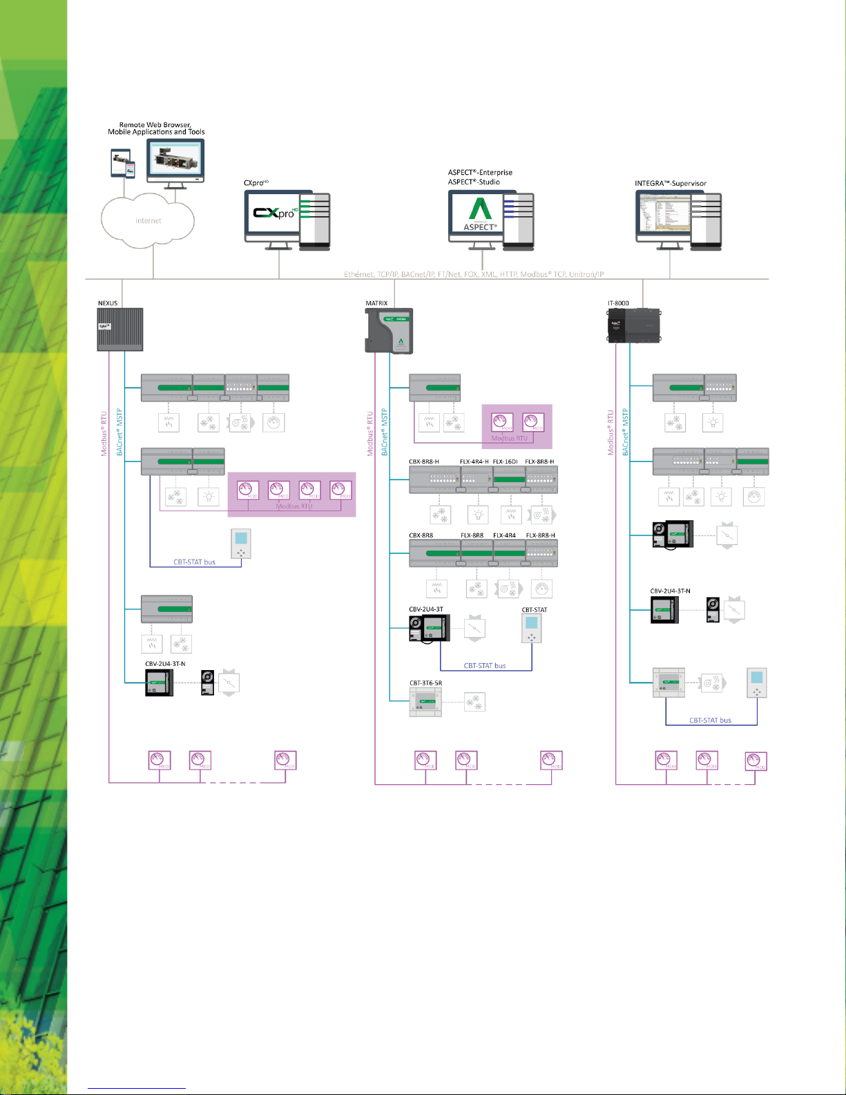
SYSTEM ARCHITECTURE
DS0119 rev 40 ©2018 Cylon All Rights Reserved. Subject to change without notice
WWW.CYLON.COM
WWW.CYLON-AUTOMATRIX.COM
page 5 of
14
CBX System
TECHNICAL DATASHEET & INSTALLATION GUIDE
INSTALLATION GUIDE
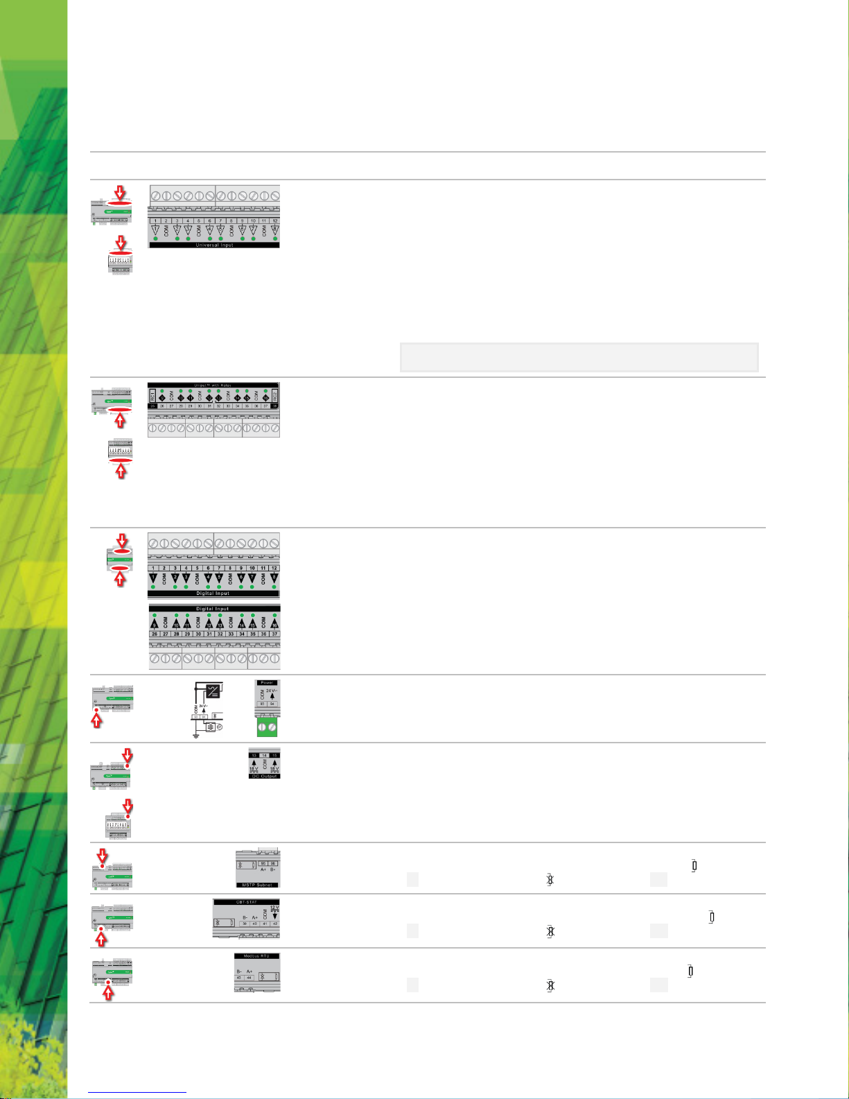
TERMINALS
Location
Illustration
Terminal
Numbers
Description
1 … 12
Universal Inputs
When input is configured as
Digital
:
• LED
Off
: open circuit or logic 'off'
• LED On: logic 'on'
When input is configured as
Resistor/thermistor
:
• LED
Off
: valid resistance connected (
Note
: 0 Ω is counted as valid)
• LED
Slow blink
: resistor/thermistor not connected
When input is configured as
Analog
:
• LED intensity is modulated by the analog signal
When the LED is blinking:
•
Fast blink
indicates error condition
•
Two short flashes followed by a value*
indicates the input is in an override state (overridden
by CXpro
HD
).
*Note: The LED intensity illustrates the value measured at the input terminals. The flash
indicates that this value has been overridden.
25 … 38
UniPuts™ + Relay
When a UniputTM channel is configured as an input, the LED signals are identical to Universal Inputs
above. When configured as an output the following apply:
When output is configured as
Digital
:
• LED
Off
: open circuit or logic 'off'
• LED On: logic 'on'
When output is configured as
Analog
:
• LED intensity is modulated by the analog signal
When the LED is blinking:
•
Fast blink
indicates error condition
•
Two short flashes followed by a value
indicates the output is in an override state
(overridden by CXproHD or HOA).
1 … 12,
26 … 37
Digital Inputs (FLX16DI only)
• LED
Off
: open circuit or logic 'off'
• LED On: logic 'on'
When the LED is blinking:
•
Fast blink
indicates error condition
•
Two short flashes followed by a value
indicates the output is in an override state
(overridden by CXpro
HD
).
93, 94 24 V AC Power
13 … 15
Auxiliary Power: 18 V DC o utput on 2 terminals, 60 mA total
95, 96
BACnet® MS/TP Port (RS-485) screw terminal
MS/TP subnet terminator switch is located beside the port. If the switch is towards the icon, then
termination is in and if the switch is towards the icon then termination is out.
39 … 42
UCU Room Display / CBT-STAT Port
The CBT-STAT bus Terminator Switch is located beside the port. If the switch is towards the icon, then
termination is in and if the switch is towards the icon then termination is out.
43, 44
Modbus RTU
The Modbus Terminator Switch is located beside the port. If the switch is toward s the icon, then
termination is in and if the switch is towards the icon then termination is out.

DS0119 rev 40 ©2018 Cylon All Rights Reserved. Subject to change without notice
WWW.CYLON.COM
WWW.CYLON-AUTOMATRIX.COM
page 6 of
14
CBX System
TECHNICAL DATASHEET & INSTALLATION GUIDE
Location
Illustration
Description
Service Port (Micro USB)
8-Way MS/TP address DIP switch (CBX only)
The controller’s BACnet® MAC address can be set either electronically (USB or BACnet®) or manually using the 8-way
DIP swi tch.
1)
Manual setting for ease of replacement
: Setting the 8-way DIP sw itch to an address between 1 and 254, and
then cycling the power, will force the controller to update its MAC address to match the DIP settings. To
replace a manually-addressed controller in the field simply copy t he DIP s witch setting of the controller you are
replacing.
2)
Electronic setting for remote configuration
: Setting the 8-way DIP s witch to all zeros will allow the MAC address
to be set electronically either locally by USB or remotely over BACnet®.
It is also possible to use manual setting for initial commissioning, and then cycling the power to force the
controller to update its MAC address to match the DIP settings. To enable subsequent electronic configuration,
set the DIP switch to all zeros. The controller will retain the manually-set address until i t is electronically
overwritten.
5-Way FLX bus address DIP switch (FLX only).
This sets the address of the FLX unit on its local FLX bus.
Output Override (-H variants only: CBX-8R8-H, FLX-8R8-H, FLX-4R4-H)
Bottom position
: Off - outputs forced off.
Centre position
: Auto - outputs are controll ed by strategy.
Top position
: Manual – for digital outputs, the output is forced on. For analog outputs the knob setting controls the
output value.
Note: Manual position is supervised, i.e. the strategy is aware of the manual value.
Inter-module connection sockets
Inter-module connector
FLX bus terminator
Indicator LEDs
Off On Slow Blink Fast blink
Red LED
(Power)
Power is off Power is on
____
Unit Rebooting
____
Green LED
(Status)
Unit is not
running
Strategy Loaded
but no network
connectivity
Strategy Loaded and
device communicating
on network
No Strategy
loaded
Yellow LED
(FLX)
FLX bus
comms are ok
No FLX bus comm s FLX bu s address cl ash
FLX bus comms
error
During firmware upgrade the Yellow LED will remain on while the strategy/comms section reboots, and then the
LEDs will rotate Red-Green-Yellow while the IO section reboots.
Note: Durin g typical operation, the Red LED should be on, the Gree n
LED should be blinking, and the Yellow LED should be off.

DS0119 rev 40 ©2018 Cylon All Rights Reserved. Subject to change without notice
WWW.CYLON.COM
WWW.CYLON-AUTOMATRIX.COM
page 7 of
14
CBX System
TECHNICAL DATASHEET & INSTALLATION GUIDE
INSTAL LATIO N
1. Apply power to the CBX-8R8(-H) ......................................................... 7
1.1. Set the CBX MS/TP Address........................................................................... 7
1.2. Connect 24 V AC Power to the CBX-8R8(-H) ................................................ 7
2. Connect t he CBX to the MS/TP Net work
.......................................................... 7
2.1. Attach RS-485 communication wires to the MS/TP Subnet port ................ 7
2.2. Terminate the MS/TP netw ork...................................................................... 8
3. Configure the CBX-8R8(-H) for BACnet® communications ................. 8
3.1. CBX-8R8(-H) Default Settings ........................................................................ 8
3.2. Connect CXproHD to the CBX-8R 8(-H) ........................................................... 8
3.3. (If required) Set Device In stance & MS/TP Address ........................................ 8
3.4. Confirm or set MS/TP parameter s ................................................................ 8
4. Connect the CBX-8R8(-H) to FLX units ................................................. 8
4.1. Set the FLX address........................................................................................ 8
4.2. Join or terminate the FLX bus ....................................................................... 9
4.3. (If required) Set up FLX bus ext ension .......................................................... 9
5. Add the Controller to the Site ............................................................ 10
5.1. Set Controller Date and Tim e ...................................................................... 10
5.2. Set I/O to a known Safe Mode .................................................................... 10
5.3. Set up the CBX and connected FLX in a Site ............................................... 10
5.4. Set up the Controller Strategy..................................................................... 11
1. APPLY POWER TO THE CBX-8R8(-H)
1.1. Set the CBX MS/TP Address
To communicate to other MS/TP devices on a BACnet® MS/TP network, the MS/TP
address must be set to a unique address within the MS/TP subnet. Where possible,
there should be no gaps between addresses. The BACnet® Instance Number must also
be unique for the BACnet®site.
The 8-way DIP switch can be used to set the MS/TP address when the device is first
powered on.
• The address is set in binary, from 1 (0000001) to 127 (1111111).
• A switch moved to the center (towards the ‘ON’ mark) represents 1, moved
to the edge represents 0.
• The right-most switch (labeled “1”) is the least-significant bit; the switch on
the left (labeled “8”) is the most-significant bit.
00000001
Address 1
01000000
Address 64
01011000
Address 88
11111111
Address255
0000000
Software Selectable*
*Note: If it is required that t he CBX-8R8(-H)’s address can be configured r emotely via
BACnet ® or electronically via USB, t hen once the CBX-8R8(-H) has been
powered up (Installation step 1.2) the 8-way DIP switch should be set to all zeros.
Setting the 8-way DIP switch to all zeros will allow the MAC address to be set
electronica lly either local ly by USB or remotely over BACnet®.
It is also possible to use manual setting for initial commissioning, and then
cycling the power to f orce the controller to update its M AC address to match
the DIP settings. To enable subsequent electronic configuration, set the DIP
switch t o all zeros. The contr oller wil l retain th e manually-set address until it is
electronica lly overwritten.
Note: If no address had previously been set (e.g. when the device is received from the
factory), then a device tha t is powered-on with the DIP sw itch set to all zeros
will use t he last 2 digits of its s erial number as its initial address.
The MS/TP baud rate must match on all devices on the MS/TP subnet.
1.2. Connect 24 V AC Power to the CBX-8R8(-H)
For the ini tial configuration of the device, the controller must f irst be powered on .
Note: Service Port (USB connection) must no t be connec ted until after the de vice is
powered on.
The CBX-8R8(-H) requires 24 V AC supplied from an externally mounted power
transformer. One conductor of the transformer must be grounded to an earth ground
to avoid damage to the controller. This conductor will be wired to the COM (common)
terminal of the controller. The wiring diagram is shown here:
Note: Ensure the 24 V AC and Common wires are correctly connected to the
controller. If the wires are swapped, it may cause damage to anything
connected t o the controller.
2. CONNECT THE CBX TO THE MS/TP NETWORK
2.1. Attach RS-485 communication wires to
the MS/TP Subnet port
Wiring the RS-485 network involves connecting the A+ (95) and B- (96) terminals in a
daisy-chained configuration. One end of the network will be connected to the
Fieldbus of the Network-level controller or BACnet® router. At the other end of the
network, the last device must be “terminated” by either installing a 100 Ω … 120 Ω
resistor or, if the last device is a CBX, users can switch the MS/TP Subnet terminator
switch (located beside the MS/TP port) towards the icon. This will effectively terminate
the network. The shield (screen) must be carried through the entire network.
If the RS-485 network is wired to an eSC, then the shield will be grounded at the eSC.
If the RS-485 network is wired to a CBR, the shield must be grounded at one point on
the network as shown below:
Network-level Cont roller or Ro uter
CBX-8R8(-H)
Network Segment end
- - - - - -
CBX-8R8(-H)
Network end
Shield connected at end of
network only
Network
Termination
switch set to OFF
Shield continuous
throughout the
network
Network cable segment
daisy-chained to next device
Network Termination
switch set to ON at end
of network
Shield connected to earth
at one end of network
only

DS0119 rev 40 ©2018 Cylon All Rights Reserved. Subject to change without notice
WWW.CYLON.COM
WWW.CYLON-AUTOMATRIX.COM
page 8 of
14
CBX System
TECHNICAL DATASHEET & INSTALLATION GUIDE
2.2. Terminate the MS/TP network
If the CBX-8R8(-H) is the last device on the RS-485 network, then its MS/TP subnet
terminator switch must be set to “in”
3. CONFIGURE THE CBX-8R8(-H) FOR
BACNET® COMMUNICATIONS
3.1. CBX-8R8(-H) Default Settings
The CBX-8R8(-H) is shipped with the following default settings:
MS/TP Address: last 2 digits of the numeric portion of the seri al number*
BACnet® Instance
Number:
entire numeric portion of the Controlle r's serial number*
MS/TP Baud Rate: 38,400 bps
*Note CBX serial numbers are structured as “CCBX” followed by a sequential
number fo llowed by a letter : CCBX (numeric portion) (letter)
Note If the ‘numeric portion’ of the Controller serial number ends with ‘00’ then
the MS/TP addre ss is set to 100 rather than 0 to avoid conflict with the CBR
default MS/TP address.
e.g. If the Controller serial number is CCBX727458C, the ‘numeric portion’ is
727458. In that case the MS/TP address would be 58 and the BACnet
Instance Number would be 727458.
If the Controller serial num ber is CCBX812300C, the ‘numeric portion’ is
812300. In that case the MS/TP address would be 100 and the BACnet
Instance Number would be 812300.
3.2. Connect CXproHD to the CBX-8R8(-H)
Connect the laptop to the CBX-8R8(-H) through a BACnet® Router such as CBR or
ASPECT® Control Engine (ACE - Matrix or Nexus Series) via Ethernet, or directly
using a standard Micro-B USB cable.
Note: When the CXproHD PC is connec ted to the CBX USB port for the first time,
you will be pr ompted to install a driver. Install “ STMicroelectronics Virtual
COM port ”, and then sel ect the corresponding serial port i n CXpro
HD
to
connect to the CBX. If you are using Windows 8.1 this driver may not be
available by default, please c ontact Cylon TSG for a copy of the drive r.
Once connected to the controller, it is possible to change the settings on the
controller using CXpro
HD
- for details see the CXproHD User Guide (MAN0133)
available from the Cylon support site (http://support.cylon.com
).
Note: It is not requ ired to cha nge the Site Number or Comms Controller preset
values. It is however recommended to match the Field Controller address
with the MS/TP Station a ddress (see below).
3.3. (If required) Set Device Instance & MS/TP
Address
Note: This is only possible if the MS/TP address switch is set to Zero.
3.4. Confirm or set MS/TP parameters
MS/TP Baud Rate is the Baud rate at which all the other devices on the subnet
(Fieldbus) are communicating. All devices must be configured for the same baud
rate for communications on the subnet.
Device ID is the BACnet device instance number. Every BACnet controller within
the site must receive a unique BACne t instance number to ensure pr oper
communications. This BA Cnet i nstance number should be unique even across
subnets. By default, it is set is set to the entire numeric portion of the Controller's
serial number. See the Cylon BACnet® Manual (MAN0106US) for further
information.
Device Name is the user-assigne d name for the controller. This is not necessary
for BACnet communications; however, it is useful to name each controller for
organizational purposes.
APDU Timeout Seconds leave this at the default setting of 3 seconds.
MS/TP Station is the device MS/TP address. This is the unique address users
must give each controller on the subnet (Fieldbus).
MS/TP Max Masters is the maximum address that this controller will poll when in
the “poll for masters” state. Because thi s is a BACnet master device, it will go into
this state to search for the next BACnet master device to pass the token to. To
optimize the speed of the netw ork, it is recommended that the last master device
on the subnet be set at the maximum MS/TP addre ss on the network. For
example, if the last device on the subnet (Fieldbus) is the CBX at address 63, then
users would set the MS/TP Max Masters to 63. This will speed up
communications as it will not go into the “poll for masters” state and immediately
pass the token back to the eSC or CBM at MS/TP address 0.
See the Cylon BACnet® Manu al (MAN0106US ) for more details regarding this
functionality and for other tips on optimizing the BACnet network.
4. CONNECT THE CBX-8R8(-H) TO FLX
UNITS
The I/O capabilities of a CBX-8R8(-H) can be extended by the addition of FLX-8R8
and FLX-8R8-H devices.
These are connected to the CBX-8R8(-H) by means of a standard module
interconnector (FLX bus connector), one of which is shipped with each FLX device.
4.1. Set the FLX address
Each of the FLX units connected to a single CBX must have an address that is
unique on that CBX’s FLX bus. The address is set by the 5-way DIP switch.
The terminals on a FLX unit will be accessible within the CBX Strategy with point
numbers prefixed by this address as illustrated below:
Inter-module bus
Address
DIP switch setting Point numbers
00001
1
101 … 116
00010
2
201 … 216
00011
3
301 … 316

DS0119 rev 40 ©2018 Cylon All Rights Reserved. Subject to change without notice
WWW.CYLON.COM
WWW.CYLON-AUTOMATRIX.COM
page 9 of
14
CBX System
TECHNICAL DATASHEET & INSTALLATION GUIDE
Note: If there are 2 devices on the same FLX bus w ith the same address –including
0, the address of the CBX - then the bottom (yellow) status LED wil l blink
slowly to indicate a FLX bus address clash
4.2. Join or terminate the FLX bus
Place the devices side-by-side and place the FLX bus connector into
the two adjacent sockets at once.
The end device on a CBX set (either a FLX device or the CBX itself if no FLX devices
are connected) must have a terminator inserted into its interconnector socket.
One terminator is shipped with each CBX-8R8(-H) device.
4.3. (If required) Set up FLX bus extension
If a FLX device cannot be located beside a CBX device or another FLX device then
The FLX bus can be connected by cable using two FLX-RMC Remote Module
Connectors, sold separately.
Connect cables to the two supplied FLX-RMC screw-terminal connectors as shown
above with the appropriate length of cable.
Note: Use Copper or Copper Clad Aluminum conductors only. Multiple wired
connections can be used between FLX mod ules, but the t otal FLX bus FL X
bus length must not exceed the following lengths:
Cable gauge
Max length
AWG 18
30 m / 100 ft.
AWG 22
15 m / 50 ft.
Remove the Interconnect (if installed) from the right-hand side of the FLX or CBX
where the RMC is to be installed.
Slide one RMC connector into the T-slot of the CBX or FLX at the point at which
the BUS is to be extended.
Replace the Interconnect
Slide the other RMC connector into the Left-Hand T-slot of the remote FLX.
Insert the second interconnect

DS0119 rev 40 ©2018 Cylon All Rights Reserved. Subject to change without notice
WWW.CYLON.COM
WWW.CYLON-AUTOMATRIX.COM
page 10 of
14
CBX System
TECHNICAL DATASHEET & INSTALLATION GUIDE
5. ADD THE CONTROLLER TO THE SITE
5.1. Set Controller Date and Time
Use CXproHD to set the controller’s Date and Time.
Alternatively, if a device on the site has been set up as a Time Sync Master, then
the CBX-8R8(-H) controller time will be automatically updated.
5.2. Set I/O to a known Safe Mode
Before connecting equipment to the CBX-8R8(-H) or FLX devices, carry out a Wipe
Controller command from CXpro
HD
to put I/O into a Kno wn Safe Mode :
• In CXpro
HD
select Wipe Controller from the Controller tab on the Ribbon .
In the Wipe Controller dialog, click in the ' Wipe All' checkbox.
• Click on the ' Wipe ' button.
When the Wipe operation is complete, a ' Controller Wiped ' message is displayed:
5.3. Set up the CBX and connected FLX in a
Site
In the Cylon Configuration Utility (CCConfig) select the CBR Comms Controller to
which the CBX device is connected, and add a new controller by clicking the Add
button:
In the New Field Controller Details dialog change the Controller Type to CBX8R8.
This will cause an I/O Modules table to become visible in the New Field Controller
Details dialog:
If the CBX device has one or more FLX modules connected to it, add the same
number of entries in the I/O Modules table:
When FLX modules have been added, the specific FLX type can be set in the I/O
Modules Table Type Column:

DS0119 rev 40 ©2018 Cylon All Rights Reserved. Subject to change without notice
WWW.CYLON.COM
WWW.CYLON-AUTOMATRIX.COM
page 11 of
14
CBX System
TECHNICAL DATASHEET & INSTALLATION GUIDE
If you attempt to add more modules than the CBX can support, an error message
will be displayed:
When the correct number of FLX modules has been added, enter a Device Instance
number and click OK.
Note: The IO module configuration can be changed later by openin g the FL X
Module Configuration dialog fr om the Site Tree :
In the Strate gy drawing, IO blocks can be added up to the total on the configured
FLX modules plus the CBX onboard IO.
Note: If a FLX module is deleted fr om a CBX configuration (in CCConfig) after the
Strategy drawing has been set up, the blocks associa ted with that FLX’s IO
will be ‘greyed out’ to indicate that they are inactive.
5.4. Set up the Controller Strategy
In CXproHD, double-click on the controller in the Site Tree to open its Strategy:
If there is no existing Strategy in the controller, an invitation to cre ate a new one
will be displayed:
Click Yes to open a new blank stra tegy drawing:
Add strategy blocks and points to create the required strategy – see MAN0133
CXpro
HD
User Guide for m ore detail.
Note that in CBX-8R8(-H) controllers there are:
• a total of 1024 strategy bl ocks, numbered 1 - 1024
• a total of 1024 analog virtual points 1 - 1024
• a total of 1024 binary virtual points 1 - 1024
• a minimum of 16 and a maximum of 64 hardware points:
oThe first 16 are nu mbered 1-16, represent ing the intern al I/O in the CBX
oThe 16 points in an attached FLX with MS/TP address set to “1” are numbered 1 01-116
oThe 16 points in an attached FLX with MS/TP address set to “2” are numbered 2 01-216
oThe 16 points in an attached FLX with MS/TP address set to “3” are numbered 3 01-316

DS0119 rev 40 ©2018 Cylon All Rights Reserved. Subject to change without notice
WWW.CYLON.COM
WWW.CYLON-AUTOMATRIX.COM
page 12 of
14
CBX System
TECHNICAL DATASHEET & INSTALLATION GUIDE
OPERATION
Inputs and Outputs ............................................................................................... 12
Auxiliary Power out puts ....................................................................................... 13
Using a Keypad with the CBX ............................................................................... 13
Output Override .................................................................................................... 14
Inputs and Outputs
The CBX-8R8(-H), FLX-8R8 and FLX-8R8-H have identical I/O capabilities – each has
a set of 8 Universal Inputs and a set of 8 UniPuts
TM
with relay.
FLX-4R4 and FLX- 4R4-H have 4 Universal Inputs and 4 UniPuts
TM
with relay.
FLX-16DI has 16 Digital Inputs only.
Any of the terminals can be configured as inputs. Any of the UniPut™ terminals
can be configured as an output.
Input modes
Universal Input terminals and UniPut™ terminals can be configured as inputs in
almost identical fashion:
Measurement
Mode
Universal Input
UniPut™ as Input:
Digital
Input
Resistance
Resistance measurement
Range: 0 ... 450 kΩ
Accuracy: ±0.5% of measured resistance
-
Temperature measurement
Range: -40 °C ... +110 °C
Accuracy: 10k NTC sensors (e.g. 10k Type 2 (10K3A1) o r
10k Type 3 (10K4A1) : ±0.3 °C, -40 to 90 °C (-40°F
to 194°F); ±0.4 °C > 90 °C (194°F)
-
Digital Volt-Free contact, 2 mA contact-wetting c urrent
Pulse counting (volt-free)
up to 20 Hz, 25 ms – 25 ms
-
-
24 V AC Detect
-
Voltage
Analog Input
Range: 0 ... 10 V
@ 130 kΩ
Accuracy: ±0.5% f ull scale
[50mV]
Analog Input
Range: 0 ... 10 V
@ 40 kΩ
Accuracy: ±0.5% full scale
[50mV]
-
Pulse counting (0 … 10 V) up t o 20 Hz, 25 m s – 25 ms -
Current
Current input
Range: 0 ... 20 mA
@ 390 Ω
Accuracy: ±0.5% full sca le
[100μA]
Current input
Range: 0 ... 20 mA
@ 390 Ω
Note:
Current Input
requires user-
supplied
external 390 Ω res istance.
Accuracy: depends on
user supplied
external resistor
-
Note: Inputs use on-board 16-bit ana log to digital conve rtor.
Note: All inputs and outputs are protecte d against short circuit, as well a s over-
voltage up to 24 V AC.
Hardware point numbers for these inputs in the CBX-8R8(-H)'s strategy:
CBX
1
… 8
9
… 16
FLX address 1
101
…
108
109
…
116
FLX address 2
201
…
208
209
…
216
FLX address 3
301 … 308 309 …316
Resistance Input mode (Passive Input)
Passive Inputs are all those devices that vary in resistance, including switch
contacts. These all require a current supplied by the CBX-8R8(-H) terminal so that
this resistance can be measured.
The passive sensor types supported by the CBX-8R8(-H) are:
• Pre-programmed Passive Temperature Sensors.
• Potentiometer (normally used as a 0 to 10 KΩ or a 1 KΩ to 11 KΩ variable
resistor to give a 0 to 100 % output).
• Volt-Free Digital Input (the controller strategy measures the contact resistance
and gives a 0 or 1 output).
• Straightforward Resistance measurement. This can be used with the Make
Linear block to give a temperature output for temperature sensors that are not
factory pre-programmed into the CBX-8R8(-H).
In CXproHD simply select ‘Resistance ’ sensor type in the Point Module and select
Pulsed in the Advanced parameters (the Pulsed option increases accuracy by
eliminating any self-heating in the passive temperature sensor, while the
Continuous option can trade absolute accuracy for speed).
In Passive Input Mode the Uniputs™ and Universal Inputs configure like this:
Note: The refere nce voltage can be pulsed or continuous, using the solid state
switch.
A pulsed reference gives optimum accuracy by eliminating self-heating in
the sensor, and this is the defa ult setting.
UniPutTM 24 V AC Detection
If 24 V AC is connected to a Uniput™ terminal, then the 24 V AC Detect circuit will
detect this and will open switch SW1. SW1 stays open for the duration of the 24 V
AC state. When 24 V AC is removed from the Uniput™ terminal then the short
circuit or open circuit states can again be detected.
Voltage input mode (Active Input)
Note: Inp ut Impedance for Univer sal Input terminals is 130 kΩ.
Input Impe dance for Uniput™ terminals is 40 kΩ.
The 0 … 10 V input is used for Active analog and binary measureme nts. ‘Active’
means that there is no current supplied by the CBX-8R8(-H) fo r the sensor, as the
signal is generated completely by the Sensor.
The ‘mV’ sensor setting gives a value between 0 and 10,000, which represents
voltage in mV.
In 0 ... 10V Input Mode, the Uniputs™ configure like this:

DS0119 rev 40 ©2018 Cylon All Rights Reserved. Subject to change without notice
WWW.CYLON.COM
WWW.CYLON-AUTOMATRIX.COM
page 13 of
14
CBX System
TECHNICAL DATASHEET & INSTALLATION GUIDE
Current Input mode (Active Input)
The Current Input is used for 0 ... 20 mA or 4 ... 20 mA Active sensors.
4 ... 20 mA scaling can easily be achieved using CXproHD by entering range
values in the Point Module ‘ Advanced ’ parameters.
Output modes
UniPut™ terminals can generate an output as follows:
Analog Output 0 ... 10 V, 20 mA, 12-bit resolution
Digital Output 0 ... 10 V, 20 mA
Relay Contacts with ability to switch up to 24 V AC
Maximum Load: 24 V AC, 2 (1) A resistive (inductive) for all relay contacts
Analog 0 … 10 V output mode
In Analog 0 ... 10 V output Mode, the UniputsTM configure themselves like this:
where the D/A is the digital to analog converter. All circuitry is fully protected
against 24 V AC .
Digital 0 … 10 V output mode
In Digital 0 ... 10 V output Mode, the Uniputs™ configure in the same way as for
analog:
In this mod e the output toggle s between the volt ages defined as “ON” and “OFF”.
Relay Mode
In Relay mode the UniputsTM are configured with a single relay common for each
half of the terminals:
Auxiliary Power outputs
The CBX and FLX modules each have two 18 V DC outputs, for I/O devices that
require loop power.
For 3-wire connections return can be through any COM terminal, but it is
recommended that Auxiliary power wiring is through terminal 14, the COM
between the two Auxiliary power terminals.
The DC output terminals provide a minimum of 18 V DC, but the combined load
(on each IO module) must remain below 60 mA.
Using a Keypad with the CBX
A CBT-STAT or UCU Room Display keypad can be connected to the CBX at the
CBT-STAT port.
Note: If UCU Room Display is used, refer to t he DS0064 UCU10FC/K for the
corresponding Strategy Point Setup.

DS0119 rev 40 ©2018 Cylon All Rights Reserved. Subject to change without notice
WWW.CYLON.COM
WWW.CYLON-AUTOMATRIX.COM
page 14 of
14
CBX System
TECHNICAL DATASHEET & INSTALLATION GUIDE
Output Override
HOA variants (CBX-8R8-H, FLX-4R4-H and FLX-8R8-H) include hardware override
switches for each of their outputs. The override controls are located behind the
flap on the front of the device:
CBX-8R8-H
FLX-4R4-H
FLX-8R8-H
And consist of a switch and a rotary knob for each output:
The channel number correspon ding to the switch is shown directly below the switch.
The switch can be set to one of 3 position s:
When a switch is set to the
Centre position
the
corresponding output channel is set to Auto mode – the
output is controlled by strategy.
The rotary knob has no effect in this mode.
When a switch is set to the
Bottom position
the
corresponding output is forced to Off – both the strategy
setting and the rotary knob have no effect.
When a switch is set to the Top position the corresponding
output is set to Manual mode
• for digital outputs, the output is forced on
• for analog outputs the rotary knob setting controls the
output value.
Note: Manual positi on is super vised, i.e. the strategy is
aware of the manual value.
The Controller Strategy can determine if an override is in place is by connecting to
the Override point on the output module:
The value of the Override point will be '0' when the output is active and ‘1’ when
the point has been manually overridden. This allows the strate gy to react to the
fact that a point has been overridden.
Note: The corres ponding terminal LED will indicate the override condition.
 Loading...