

Cylon CBX series, FLX-4R4-H, FLX-8R8, CBX-8R8, FLX-8R8-H Technical Datasheet And Installation Manual
...
DS0119 rev 40 ©2018 Cylon All Rights Reserved. Subject to change without notice
WWW.CYLON.COM
WWW.CYLON-AUTOMATRIX.COM
page 1 of
14
TECHNICAL DATASHEET & INSTALLATION GUIDE
CBX System
CBX System
CBX-8R8|CBX-8R8-H|FLX-4R4|FLX-4R4-H|FLX-8R8|FLX-8R8-H|FLX-16DI
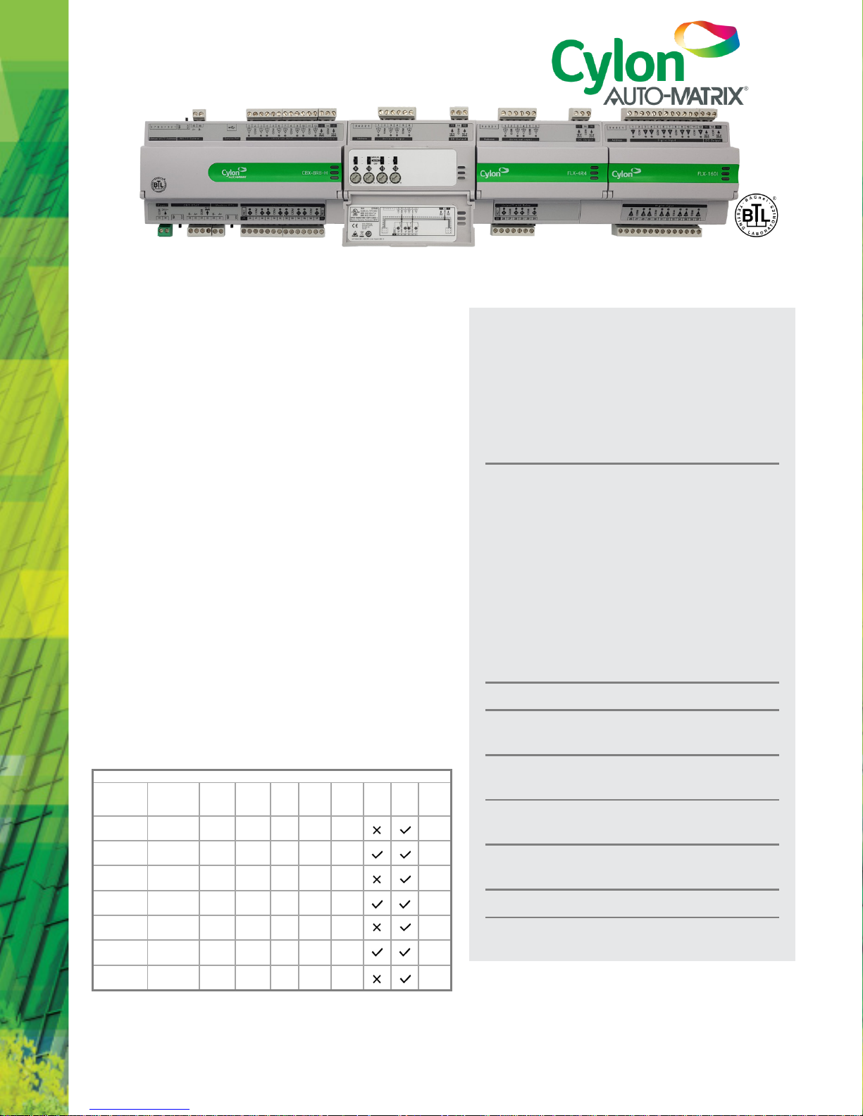
DESCRIPTION
The CBX-8R8(-H) is a fully programmable BTL-listed BACnet®
Advanced Application Controller (B-AAC) that communicates on
an RS-485 local area network using the BACnet® MS/TP protocol.
This controller features 8 UniPuts™ with Relay and 8 Universal
Inputs as well as support for up to three FLX (Field Level
eXpansion) series extension modules providing up to 64 points
of control. FLX expansion modules are available in a variety of
options to allow maximum flexibility in achieving the required
point configuration.
The CBX-8R8(-H) is designed for a wide range of applications for
intelligent control of HVAC equipment, lighting control, and
electrical systems including metering applications.
APPLICATION
The CBX-8R8(-H) is suitable for controlling various equipment
such as; air handling units, boilers, chillers, cooling towers, pump
systems, central plant equipment, variable frequency drives,
lighting control and metering. The controller supports multi-
protocol communications simultaneously including BACnet®
MS/TP and Modbus® RTU.
The fully programmable CBX-8R8(-H) can be tailored to meet a
variety of applications by creating and modifying strategies using
Cylon's CXpro
HD
programming interface.
Product Selection Chart
Part Number
Module
Service
UniPutsTM
with Rel ay1
Universal
Inputs
Digital
Inputs
Modbus
RTU
Devices
CBT-STAT
Bus
HOA
Switch
& Pot.
18 V
Aux
Power
FLX
I/O
Modules
CBX-8R8
Main
Controller
8 8 0 4* 1
3
CBX-8R8-H
Main
Controller
8 8 0 4* 1
3
FLX-4R4
Expansion
Module
4 4 0 0 0
-
FLX-4R4-H
Expansion
Module
4 4 0 0 0
-
FLX-8R8
Expansion
Module
8 8 0 0 0
-
FLX-8R8-H
Expansion
Module
8 8 0 0 0
-
FLX-16DI
Expansion
Module
0 0 16 0 0
-
Note: 1 – UniPutsTM are software configurable for point types AI, DI, AO or DO-R.
Note: * – CBX Modbus® RTU supports a total of 40 points across 4 devices
CBX-8R8
8 UniPuts™ + Relays
hardware connections that can be used as
inputs, outputs or relays (software selectable)
8 Universal Inputs
CBX-8R8-H
Including Hand/Off/Auto Local Override
Function
Field Level eXpansion Modules
FLX-4R4
4 UniPuts™ with Relay
4 Universal Inputs
FLX-8R8
8 UniPuts™ with Relay
8 Universal Inputs
FLX-16DI
16 Digital Inputs
FLX-4R4-H, FLX-8R8-H
Including Hand/Off/Auto Local Override
Function
Support for Cylon smart thermostat bus
LED status on all I/O channels provides
indication of fault or override status
Compact form factor to maximize enclosure
space
Scalable from 16 points to 64 points using FLX
modules
Easy module expansion using simple bus
connectors
Up to 64 Trendlogs, 1024 entries per Trendlog
Accurate Universal Inputs support a variety of
thermistors and RTDs that range from 0 to 450 kΩ
INSTALLATION GUID E : see page 5
DS0119 rev 40 ©2018 Cylon All Rights Reserved. Subject to change without notice
WWW.CYLON.COM
WWW.CYLON-AUTOMATRIX.COM
page 2 of
14
CBX System
TECHNICAL DATASHEET & INSTALLATION GUIDE
SPECIFICATIONS
MECHANICAL
Size
(excluding terminal plugs)
CBX-8R8
CBX-8R8-H
166 x 89.5 x 57 mm [6.5 x 3.55 x 2.25”]
FLX-4R4
FLX-4R4-H
FLX-8R8
FLX-8R8-H
FLX-16DI
104 x 89.5 x 57 mm [4.1 x 3.55 x 2.25”]
Enclosure
Flame-Retardant ABS
DIN 43880 type-2 compatible
Mounting
DIN rail
CONNECTION
Note: Use Copper or Copper Clad Aluminum 70 °C conductors only.
Terminals
PCB mounted plug terminal connections
Conductor Area
Max: AWG 12 (3.31 mm2)
Min: AWG 22 (0.355 mm
2
)
ENVIRONMENT
Note: This equipment is intended for field instal lation within an enclosure.
Ambient Temperature
-25 °C … 50 °C (-13 °F … 122 °F)
Ambient Humidity
0% … 90% RH non-condensing
Storage Temperature
-30 °C … +70 °C (-22 °F … 158 °F)
EMC Immunity
EN 61326-1: 2013
EMC Emission
EN 61326-1: 2013
EN 61000-3-2: 2014
EN 61000-3-3: 2013
Approvals
UL Listed (CDN & US) UL916 Energy Management
Equipment – File No. E176435
ELECTRICAL
Supply Requirements
24 V AC ±20 % 50/60 Hz
Supply
Rating
CBX
50 VA (no FLX modules)
CBX + 1 x FLX
66 VA
CBX + 2 x FLX
82 VA
CBX + 3 x FLX
98 VA
FLX Power
Connection Proprietary FLX bus connector carries power and
comms from CBX-8R8(-H) unit. CBX-8R8(-H) can
supply power to up to 3 FLX modules.
Auxiliary
Power 18 V DC / 60 mA output
BACnet® Loading
¼ unit load device
PROCESSOR
Type
STM32 ARM Cortex-M3 proce ssor
Clock Speed
8 MHz crystal, 72 MHz internal processor clock rate
System Memory
1MByte external SRAM + 16 Mbyte external flash
(soldered to PCB not removable)
Real
-Time Clock Battery backed for 2 years minimum
COMMUNICATIONS
Local serial port
USB Micro-B socket (used as service port)
BACnet
® MS/TP port RS485 @ 9K6,19K2, 38K4, 57K6, 76K8 or 115k2
Baud
(defaults to 38K4). Max cable length 1.2 km
Modbus Port
Support for Modbus RTU
(4 Modbus devices or 40 points)
CBT-STAT Port
RS485 with a maximum cable length 500 m
FLX bus
115.2K Baud
Max bus length (including e xtension cables):
30 m / 10 0 ft. using 1 8 AWG conductors
15 m / 50 ft. using 22 AWG conduct ors
FLX bus Connection
FLX bus connector carries inter-module
communications and module power
INPUTS / OUTPUTS
Note: Shielded cable i s recommended for al l input connections.
UniPuts™ with Relay
When configured as Input:
Analog Input
Range: 0 ... 10 V @ 40 kΩ
Accuracy: ±0.5% full scale [50mV]
Resistance measurement
Range: 0 ... 450 kΩ
Accuracy: ±0.5% of measured resistance
Temperature measurement
Range: -40 °C ... +110 °C
Accuracy: 10k NTC sensors (e.g. 10k Type 2 ( 10K3A1) or
10k Type 3 (10K4A1) : ±0.3 °C, -40 to 90 °C (40°F to 194°F); ±0. 4 °C > 90 °C (194°F)
Current input
Range: 0 ... 20 mA @ 390 Ω
Note: Curre nt Input re quires user-supplied external
390 Ω resistanc e.
Accuracy: depends on user supplied external resistor
Digital Volt-Free contact, 2 mA contact-wettin g current
Pulse counting up to 20 Hz, 25 ms - 25 ms
When configured as
Output:
Analog Output 0 ... 10 V, 20 mA, 12-bit resolution
Digital Output 0 ... 10 V, 20 mA
Relay Contacts with ability to switch up to 24 V AC
Maximum Load: 24 V AC, 2 (1) A resistive (inductive)
for all relay contacts
Universal Inputs
Analog Input
Range: 0 ... 10 V @ 130 kΩ
Accuracy: ±0.5% full scale [50mV]
Resistance measurement
Range: 0 ... 450 kΩ
Accuracy: ±0.5% of measured resistance
Temperature measurement
Range: -40 °C ... +110 °C
Accuracy: 10k NTC sensors (e.g. 10k Type 2 ( 10K3A1) or
10k Type 3 (10K4A1) : ±0.3°C, -40 to 90°C (-40°F
to 194°F); ±0.4°C > 90°C (194°F)
Current input
Range: 0 ... 20 mA @ 390 Ω
Accuracy: ±0.5% full scale [100μA]
Digital Volt-Free contact, 2 mA contact-wettin g current
Pulse counting up to 20 Hz, 25 ms – 25 ms
Digital Inputs
Digital Volt-Free contact, 2 mA contact-wettin g current
Pulse counting up to 20 Hz, 25 ms – 25 ms
Notes: 1) All inputs and outputs are protected against short circuit, as well as over-
voltage up to 24 V AC.
2) Inputs use on-board 16-bit anal og to digital conve rtor.
3) 18 V DC supply, max 60mA per CBX/FLX unit , is available for powering
sensors.
SOFTWARE FEATURES
Maximum number of Stra tegy Blocks
1024
Maximum number of Trendlog Modules
64
Maximum internal Trendlog capacity (standard)
1024
Data Security
Strategy and Set points backed up in Flash
INTERFACE
Engineering Software
CXproHD
DS0119 rev 40 ©2018 Cylon All Rights Reserved. Subject to change without notice
WWW.CYLON.COM
WWW.CYLON-AUTOMATRIX.COM
page 3 of
14
CBX System
TECHNICAL DATASHEET & INSTALLATION GUIDE
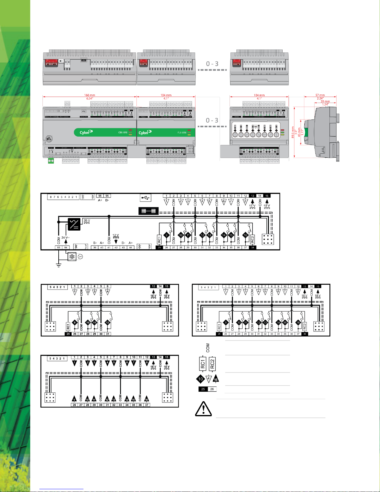
DIMENSIONS
WIRING
CBX-8R8 and CBX-8R8-H
FLX-4R4 and FLX-4R4H
FLX-8R8 and FLX-8R8H
FLX-16DI
Common
Relay Common
Point Numbers (24 V only)
Terminal Numbers
CAUTION - DANGER OF EXPLOSION IF BATTERY IS INCORRECTLY REPLACED.
REPLACE ONLY WITH THE SAME OR EQUIVALENT TYPE RECOMMENDED BY
THE MANUFAC TURER. DISPOSE OF USED BATTERIES AC CORDING TO THE
MANUFACTURER'S INSTRUCTIONS.
DS0119 rev 40 ©2018 Cylon All Rights Reserved. Subject to change without notice
WWW.CYLON.COM
WWW.CYLON-AUTOMATRIX.COM
page 4 of
14
CBX System
TECHNICAL DATASHEET & INSTALLATION GUIDE
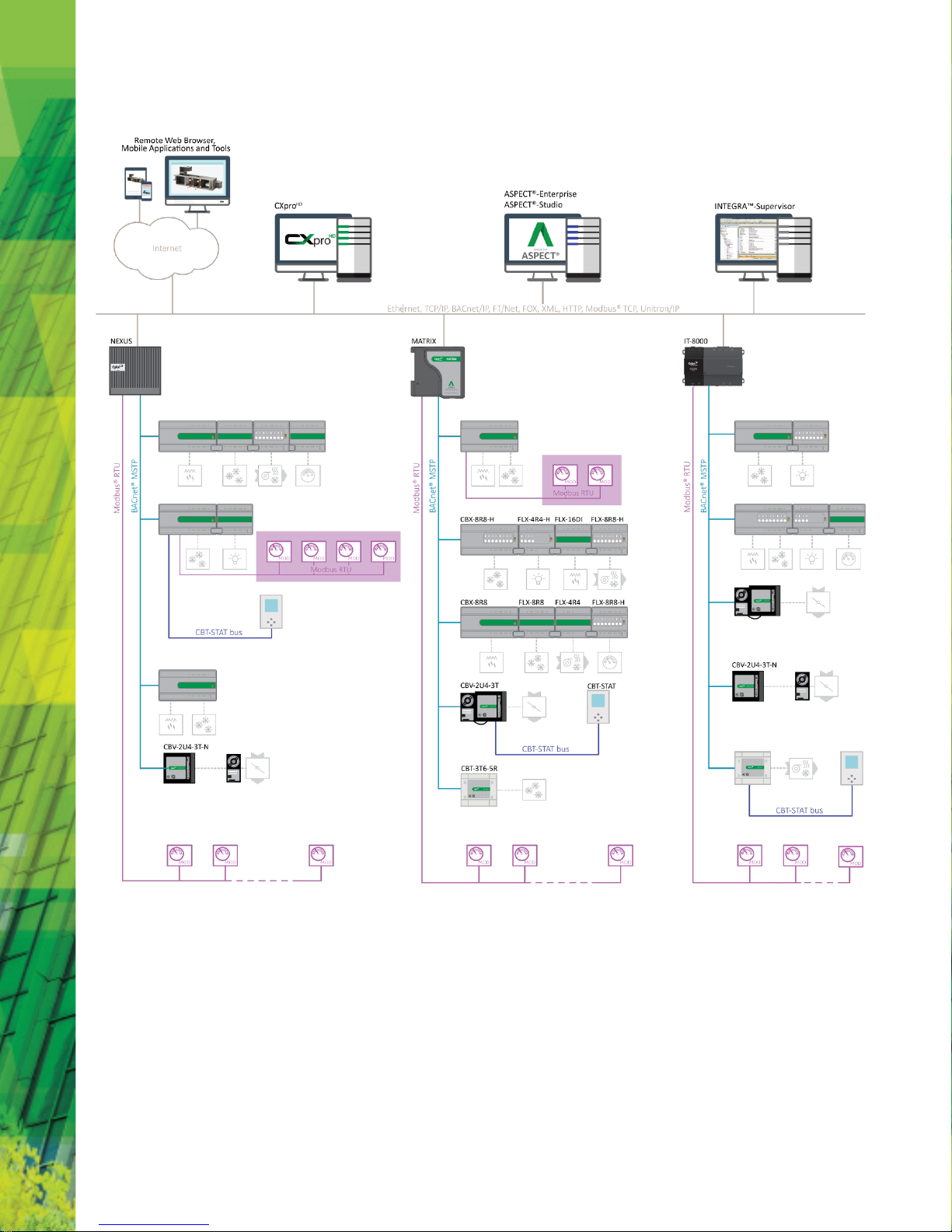
SYSTEM ARCHITECTURE
DS0119 rev 40 ©2018 Cylon All Rights Reserved. Subject to change without notice
WWW.CYLON.COM
WWW.CYLON-AUTOMATRIX.COM
page 5 of
14
CBX System
TECHNICAL DATASHEET & INSTALLATION GUIDE
INSTALLATION GUIDE
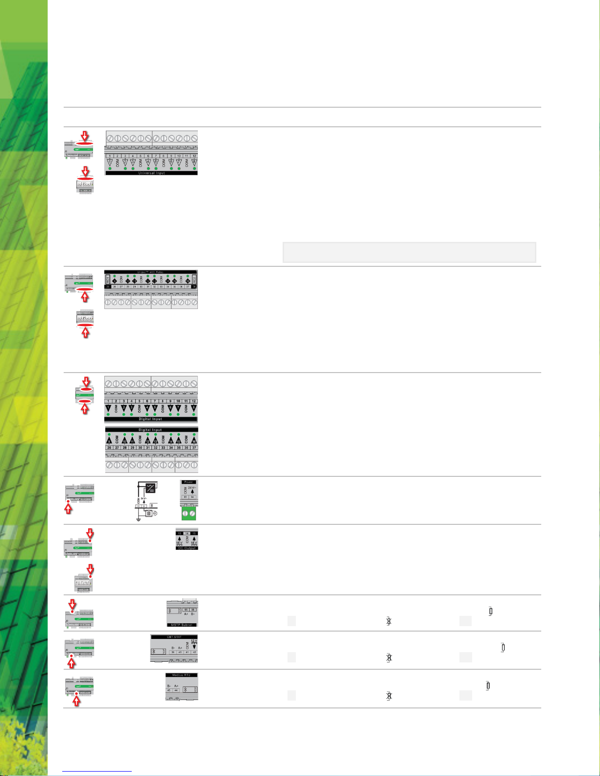
TERMINALS
Location
Illustration
Terminal
Numbers
Description
1 … 12
Universal Inputs
When input is configured as
Digital
:
• LED
Off
: open circuit or logic 'off'
• LED On: logic 'on'
When input is configured as
Resistor/thermistor
:
• LED
Off
: valid resistance connected (
Note
: 0 Ω is counted as valid)
• LED
Slow blink
: resistor/thermistor not connected
When input is configured as
Analog
:
• LED intensity is modulated by the analog signal
When the LED is blinking:
•
Fast blink
indicates error condition
•
Two short flashes followed by a value*
indicates the input is in an override state (overridden
by CXpro
HD
).
*Note: The LED intensity illustrates the value measured at the input terminals. The flash
indicates that this value has been overridden.
25 … 38
UniPuts™ + Relay
When a UniputTM channel is configured as an input, the LED signals are identical to Universal Inputs
above. When configured as an output the following apply:
When output is configured as
Digital
:
• LED
Off
: open circuit or logic 'off'
• LED On: logic 'on'
When output is configured as
Analog
:
• LED intensity is modulated by the analog signal
When the LED is blinking:
•
Fast blink
indicates error condition
•
Two short flashes followed by a value
indicates the output is in an override state
(overridden by CXproHD or HOA).
1 … 12,
26 … 37
Digital Inputs (FLX16DI only)
• LED
Off
: open circuit or logic 'off'
• LED On: logic 'on'
When the LED is blinking:
•
Fast blink
indicates error condition
•
Two short flashes followed by a value
indicates the output is in an override state
(overridden by CXpro
HD
).
93, 94 24 V AC Power
13 … 15
Auxiliary Power: 18 V DC o utput on 2 terminals, 60 mA total
95, 96
BACnet® MS/TP Port (RS-485) screw terminal
MS/TP subnet terminator switch is located beside the port. If the switch is towards the icon, then
termination is in and if the switch is towards the icon then termination is out.
39 … 42
UCU Room Display / CBT-STAT Port
The CBT-STAT bus Terminator Switch is located beside the port. If the switch is towards the icon, then
termination is in and if the switch is towards the icon then termination is out.
43, 44
Modbus RTU
The Modbus Terminator Switch is located beside the port. If the switch is toward s the icon, then
termination is in and if the switch is towards the icon then termination is out.
 Loading...