

Cylligan SY-750S Installation And Operating Instructions Manual
Specifications
Pressure Range: 30–125 psi (2.1–8.62 bar)
Temperature Range: 40–100°F (4.4–37.7°C)
Rated Service Flow: 0.75 gpm (2.8 Lpm)
Filter Capacity: 2500 gallons (9460 L)
Turbidity: 5 NTU max
Parts Included:
• Filter head with built-in bracket and compression fittings
• 750R filter cartridge
• Screws for mounting bracket
• Water supply adapter
• Lead-free drinking water faucet
• 1/4" plastic tubing
Technical Support: 1-800-645-5426
(M-F 7:30 am - 5:00 pm CST)
146153 Rev A 03/04
Easy-Change Under-Sink Drinking Water Filter
System Installation and Operating Instructions
Model SY-750S
The SY-750S with 750R or 1000R replacement cartridge is Tested and Certified by
NSF International to NSF/ANSI Standard 42 for the aesthetic reduction of Taste
and Odor and Chlorine and Particulate Class I*, Standard 53 for the reduction of
Cysts*, Lead*, Lindane*, Atrazine*, and Turbidity*.
•Phillips Screwdriver
•Utility Knife
(for plastic tubing)
•Towel
•Pencil
•Tape Measure
•Adjustable Wrench
•Safety Glasses
Tools Required
•Center Punch
•
1
/4" and 1/2" Drill Bit
•Hand or electric drill
(cordless recommended)
Optional Materials
• Make certain that installation complies with
all state and local laws and regulations.
• The contaminants or other substances removed or
reduced by the selected
cartridge are not necessarily in your water. Ask your local water municipality
for a copy of their water analysis, or have your private well tested by a
reputable water testing lab.
• After prolonged periods of non-use (such as during a vacation) it is recommended
that the system be flushed thoroughly. Let water run for 2-3 minutes before
using.
• The filter cartridge used with this system has a limited service life. Changes in
taste, odor, color; and/or flow of the water being filtered indicate that the
cartridge should be replaced.
Precautions
WARNING: Do not use with water that is microbiologically unsafe or of
unknown quality without adequate disinfection before or after the system.
CAUTION: This filter must be protected from freezing, which can cause cracking
of the filter and water leakage.
CAUTION: Because of the product’s limited service life and to prevent costly
repairs or possible water damage, we strongly recommend that the head of the
filter be replaced every ten years. If the head of your filter has been in use for
longer than this period, it should be replaced immediately. Date the top of any
new head to indicate the next recommended replacement date.
CAUTION: Turn off water supply to head without cartridge if it must be left
unattended for an extended period of time.
NOTE:
• For cold water use only.
*Applies to 1000R replacement cartridge only.
Installation
• For standard installation on 1⁄2-inch 14 NPS threads (most common thread on kitchen faucets)
cold water line.
• Please read all instructions and precautions before installing and using your SY-750S
under-sink water filter.
• Numbered diagrams correspond with numbered steps.
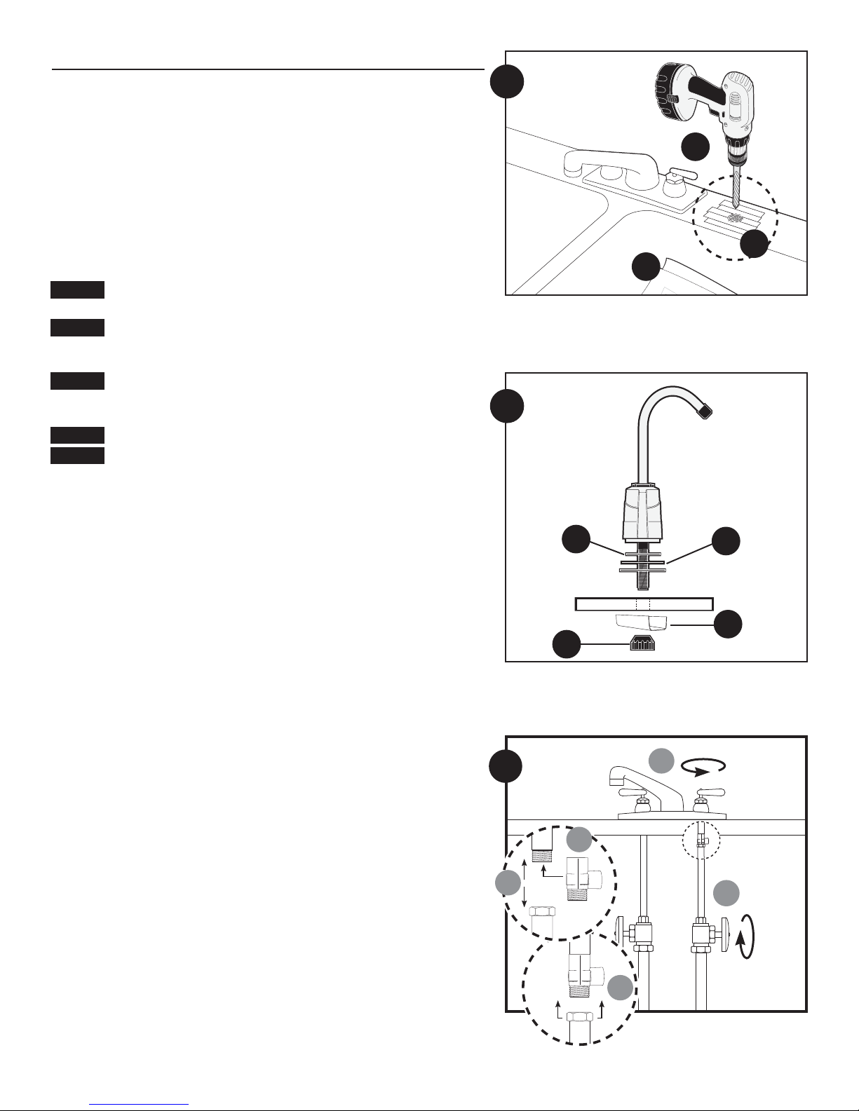
1. Selecting the Faucet Location
NOTE: The drinking water faucet should be positioned with function, convenience, and
appearance in mind. An adequate flat area is required to allow faucet base to rest securely. The
faucet fits through a
7
⁄16-inch hole. Most sinks have pre-drilled 13⁄8-inch or 11⁄2-inch diameter holes
that may be used for faucet installation or spray hose. If these pre-drilled holes cannot be used or
are in an inconvenient location, it will be necessary to drill a
1
⁄2-inch hole in the sink for the faucet.
CAUTION: This procedure may generate dusts which can cause severe irritation if inhaled or come
in contact with the eyes. The use of safety glasses and respirator for this procedure is recommended.
CAUTION: DO NOT ATTEMPT TO DRILL THROUGH AN ALL-PORCELAIN OR PORCELAIN-COATED
SINK. For applications on these types of sinks we recommend using the sprayer hole or
mounting the faucet through the countertop.
CAUTION: When drilling through a countertop make sure the area below the drilled area is free of
wiring and piping. Make certain that you have ample room to make the proper connections to the
bottom of the faucet.
CAUTION: Do not drill through a countertop that is more than 1-inch thick.
CAUTION: Do not attempt to drill through a tiled, marble, granite or similar countertop. Consult a
plumber or the countertop manufacturer for advice or assistance.
(A) Line bottom of sink with newspaper to prevent metal shavings, parts, or tools from falling
down drain.
(B) Place masking tape over the area to be drilled to prevent scratches if drill bit slips.
(C) Mark hole with center punch. Use a
1
⁄4-inch drill bit for a pilot hole, then, using a 1⁄2-inch drill
bit, drill a hole completely through the sink. Smooth rough edges with a file.
2. Mounting the Faucet
(A) Slide small black rubber gasket OR
(B) gasket, aluminum escutcheon plate (remove protective plastic on aluminum escutcheon plate)
and large gasket onto threaded faucet stem. Lower faucet stem through hole in the sink.
NOTE: Black rubber gasket is designed for smaller holes in sink. Aluminum escutcheon plate with
gaskets is designed for larger, pre-drilled holes.
(C) Slide aluminum channel washer up faucet stem, followed by
(D)black plastic stem nut. Tighten nut with fingers.
NOTE: Do not use pliers to tighten stem-nut. Pliers may strip threads of faucet stem.
3. Installing the Water Supply Adapter
The supply adapter fits 1⁄2-inch-NPS supply threads. If local codes permit, it may be used to
connect the SY-750S to the cold water supply line. If local codes do not permit the use of the
supply adapter, alternate connectors can be obtained from your local retailer.
Installing the Water Supply Adapter
(A) Turn off cold water supply line. If cold water line does not have a shut-off valve under the sink,
you should install one.
(B) Turn on the cold water faucet and allow all water to drain from line.
(C) Disconnect cold water line from
1
⁄2-inch-14 NPS threaded stub on bottom of main faucet.
(D) Apply Teflon
®
tape onto threads of faucet stub and supply adapter. Screw the water supply
adapter to the threaded faucet stub as shown.
(E) Using the nut that previously connected the cold water line to the faucet, screw the cold water
line to the male supply adapter threads.
2
C
B
A
B
C
A
D
2
1
3
A
B
E
D
C
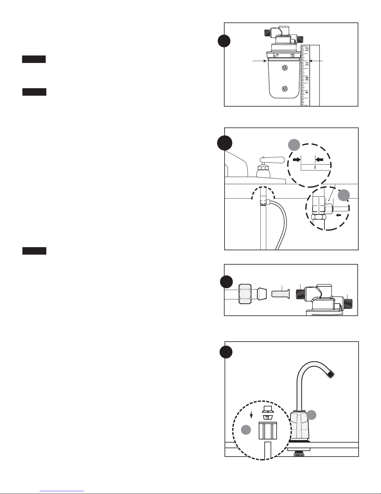
4. Mounting the Filter System
(A) Select location under sink or in basement where filter is to be mounted.
NOTE: Allow 1
1
⁄2-inches (33 mm) clearance below housing or 11-inch below filter head to enable
filter cartridge changes.
CAUTION: Filter head should be mounted on stud or firm surface. The mounting bracket will
support the weight of the filter and help prevent strain on the cold water line.
(B) Filter head should be mounted in vertical position, use mounting bracket as a template to
mark screw locations. Mount filter head in marked location using screws.
CAUTION: Water supply to the filter should have a separate shut off valve. If it does not, a
separate shutoff should be installed.
5. Connecting the Supply Adapter and
Inlet of Filter
(A) Determine the length of plastic tubing needed to connect the inlet (left) side of the filter with
the supply adapter. Be sure to allow enough tubing to prevent kinking and cut the tubing
squarely. Place a mark
5
⁄8-inch from the end of the tubing.
(B) Wet tubing with water and insert into supply adapter
5
⁄8-inch until mark is flush with fitting.
NOTE: Disconnecting the Tubing from the Quick-Connect Fittings.
Routine maintenance and cartridge replacement will not require that you disconnect the tubing
from the filter system; however, tubing may be quickly and easily removed from the fitting if
necessary. First, turn off the water supply to the filter. Open faucet, then press in the grey
collar around the fitting while pulling the tubing with your other hand.
(C) Slide brass compression nut onto tubing, followed by white plastic ferrule. The long tapered
end of the ferrule should face towards the end of the tubing and the tubing should extend
through the ferrule about
1
⁄4-inch. Place insert into end of tubing. Insert tubing into inlet of fil-
ter and hand-tighten compression nut. Using a wrench, tighten nut 1 to 1
1
⁄2 turns. Be careful
not to cross thread filter threads.
6. Connecting the Faucet
CAUTION: Do not over-tighten compression nut. Use caution not to bend or crimp tubes when
securing.
(A) Determine the length of plastic tubing needed to connect the outlet (right) side of the filter
with the faucet. Measure tubing short enough to prevent kinking and cut the tubing squarely.
Screw nut on faucet stem hand tight, then unscrew two turns.
NOTE: Compression nut should come preassembled with ferrules inside. If nut should come apart,
see Figure 6A for proper assembly.
(B) Push the tubing firmly into the end of the nut and faucet stem. Hand-tighten compression nut
onto threads until secure. Then tighten 1
1
⁄2 to 2 turns with wrench.
(C) Connect outlet of filter using step 5c.
7. Installing the Cartridge
Hold cartridge from the bottom when installing or changing the cartridge. Use caution not to scrape
knuckles on bracket when locking the cartridge into place. Line up the arrow on the cartridge with
unlocked padlock on head. Insert cartridge and turn arrow to locked padlock. See Diagram R4 in
Filter Cartridge Replacement on page 4.
8. Putting the Filter into Operation
(A) Turn on water supply valve. Check for leaks. If it leaks, see Troubleshooting.
(B) Rotate base of drinking water faucet counter-clockwise to "on position." Allow water to run for
5 minutes to flush air and carbon fines (very fine black powder).
(C) Check for leaks before leaving installation. If it leaks, see Troubleshooting.
PLASTIC TUBING
6
B
A
Nut
Insert
Plastic
Ferrule
3
5
A
B
5/8"
16 mm
5/8"
16 mm
5c
Inlet
Outlet
to faucet
4B
4
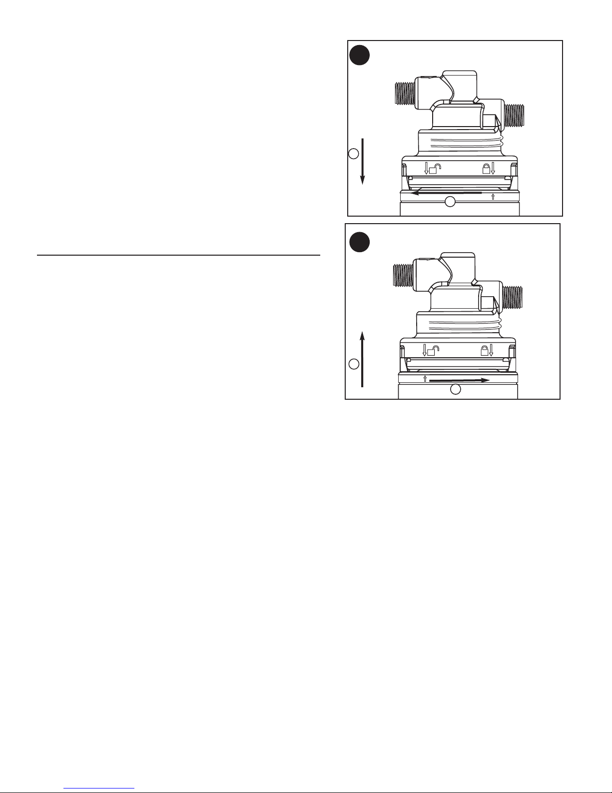
R. Filter Cartridge Replacement
NOTE: It is recommended that the filter be replaced every year, or when you notice a
change in taste, odor, or flow of the water being filtered.
(1) Turn off water supply to the filter and dispense water from drinking water faucet until
water flow stops to relieve pressure.
(2) Place towel under the system to catch any water drips.
(3) (a) Turn arrow from locked to unlocked position and
(b) remove cartridge.
(4) (a) Line up arrow with unlocked position on head and insert cartridge.
(b) Turn to locked position.
(5) Turn on water and check for leaks. If it leaks, see Troubleshooting.
(6) Flush water through drinking water faucet for 5 minutes to remove carbon fines. Check
for leaks before leaving installation. If it leaks, see Troubleshooting.
Troubleshooting
Leaks:
...Between head and cartridge
(1) Turn off the water supply to the filter and dispense water from drinking water faucet
until water and airflow stops.
(2) Remove cartridge and inspect o-rings to make sure they are in place and clean.
(3) Install cartridge and turn on water supply. If it still leaks, contact Technical Support at
1-800-645-5426 M-F 7:30 AM-5 PM CST. Turn off icemaker if filtered water goes to
icemaker.
...From fittings
Turn off water supply to the filter and turn on drinking water faucet to release pressure in
system. For plastic tubing, loosen the compression nut and pull the tubing from the brass
fitting. Inspect to see if the ferrule and insert are properly installed on the tubing. Check if
tubing is cut squarely. If so, reconnect tubing finger-tight, then tighten nut snug about
1
⁄2 to
1 turn with a wrench. Open the water supply valve, then close faucet and check for leaks.
If the leaks persist, or if there are other leaks on the unit, turn off the water supply then
call Technical Support at 1-800-645-5426.
...on supply adapter connection
Turn off water supply valve and turn on drinking water faucet to release pressure in system.
Loosen leaking threaded fitting on supply adapter or pull out leaking tubing from fitting.
Inspect to see if plastic tubing is scratched or supply adapter was properly attached. If
tubing is scratched, cut off
1
⁄2-inch to 5⁄8-inch and reinstall per Step Three: Connecting the
Water Supply Adapter. Reconnect tubing or tighten compression nut with fingers, then
tighten nut snugly
1
⁄2-turn with wrench. Turn on water supply valve and check for leaks.
...on faucet/tubing connection
Turn off water supply valve and turn on drinking water faucet to release pressure. Loosen
and remove compression nut fitting on faucet stem. Check if tubing is cut squarely. Make
sure tubing is inserted firmly into end of faucet stem, then retighten compression nut with
fingers until secure, then tighten nut snugly
1
⁄2-turn with wrench. Turn on water supply
valve, then close faucet and check for leaks.
NOTE: If leaks persist, or if there are other leaks on system, turn off water supply. Call our
technical support department at 1-800-645-5426.
R3
R4
b
a
a
b
 Loading...