

Page 1
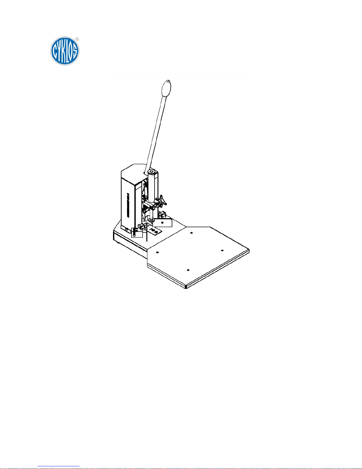
Operating Manual
Issue No.
1
No of sheets
6
Corner Rounding Machine
CCR 40
Warning
This document including the attachments is exclusive intellectual property of Cyklos Choltice
(producer cooperative). Any other use (copying, distribution or sale) is possible only with
approval of the chairman of the cooperative.
Valid from serial number:
17012461
Page 2

Operating Instructions | CCR 40
2
Contents
1 Identification ....................................................................................................... 3
2 Specifications ..................................................................................................... 3
3 Prohibited operations ......................................................................................... 3
4 Parameters......................................................................................................... 3
5 Main machine parts ............................................................................................ 4
6 Operating instructions ........................................................................................ 5
6.1 Preparing the machine for use ........................................................................... 5
6.2 Paper introduction ............................................................................................. 5
6.3 Adjustment of paper down-pressure, position 4 ................................................. 5
6.4 Tool assembly and maintenance ....................................................................... 5
6.5 Paper cutting ..................................................................................................... 6
6.6 Removal of defects ............................................................................................ 6
6.7 Cover dismounting ............................................................................................. 6
7 Machine disposal ............................................................................................... 6
Page 3

Operating Instructions | CCR 40
3
1 Identification
Type marking: CCR 40
Manufacturer: Cyklos Choltice
533 61 Choltice
Czech Republic
2 Specifications
The machine is designed for the manual rounding of paper sheets of A3, A4, A5 and A6
size down t o business card as a m inimum dimension. Optional radius R4, 6, 9, 12 and 18
mm may be used. Another option is to cut paper corners with a direct tool at an angle of
45° and with a maximum length of 28 mm. The maximum height of inserted s heets to be
adjusted is 40 mm. The rounding machine is designed to cut standard office paper or
paper with similar physical-chemical properties.
3 Prohibited operations
a) The machine is designed only for the cutting of the paper specified in the parameters
section and of a plastic foil.
b) It is prohibited to cut metal foils, tin sheets or similar materials.
c) The machine can be operated only in closed, covered areas (e.g. offices, workshops).
It is prohibited to use the machine outdoors.
d) To reduce the risk of injuries, never use the machine near children.
e) If the machine’s operation gets interrupted or stuck, or if its operation requires
inappropriate efforts, stop working and check the technical condition of the machine.
f) The machine can be operated only if it is covered and none of its parts is missing. It is
prohibited to perform any work under the machine cover and to put one’s fingers
inside the thrust screw and blades area while the machine is working (paper cutting).
g) The machine can be attended only by a person familiar with its operation.
4 Parameters
a) Sheet size A3, A4, A5, A6 and smaller (business card)
b) Radius of tools R4, R6, R9, R12, R18 and straight tool 28 mm
c) Input capacity 40 mm
d) Space requirements length = 1007 mm
width = 375 mm
height = 834 mm
e) Transport size leng th = 535 mm
width = 380 mm
height = 400 mm
f) Machine weight 17 kg
Page 4
Operating Instructions | CCR 40
4
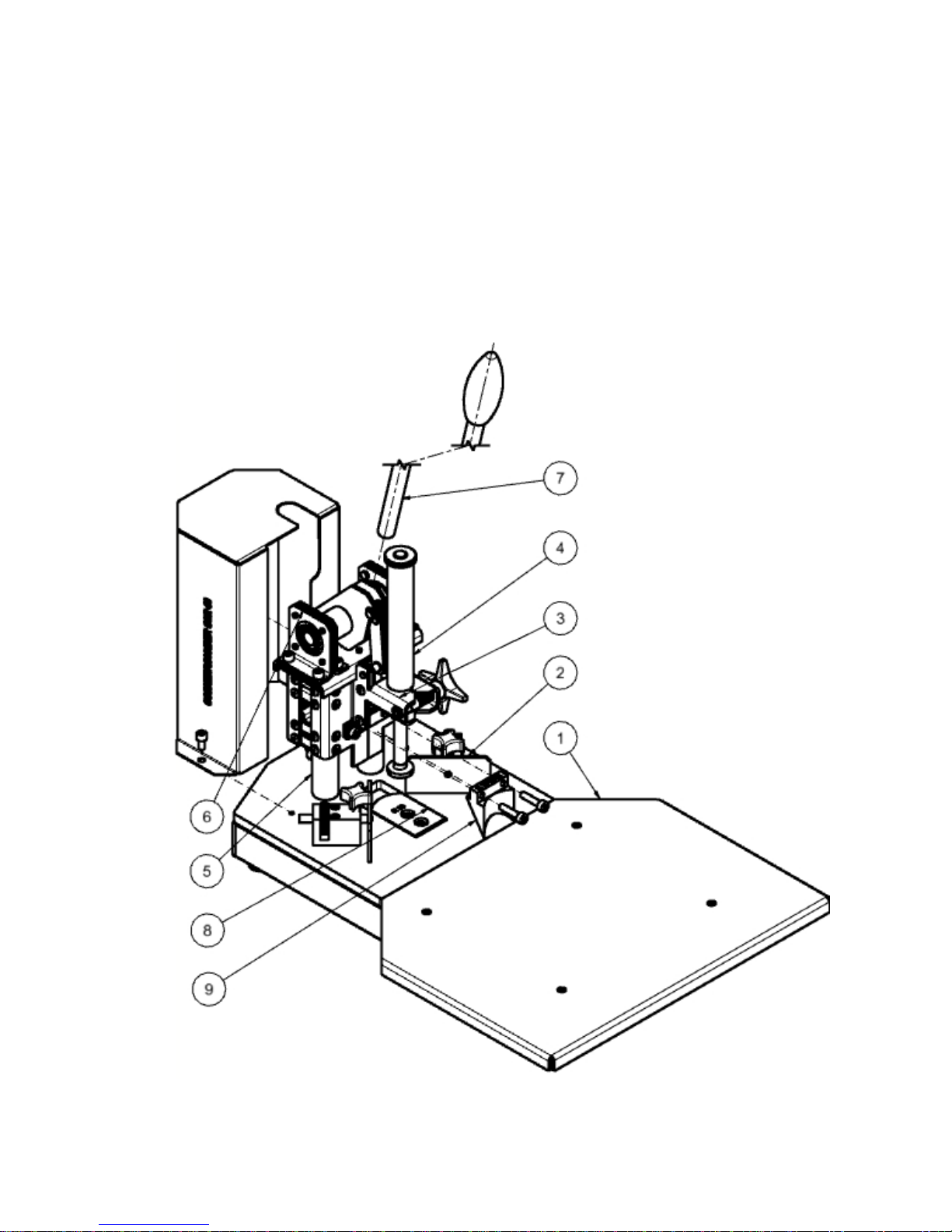
5 Main machine parts
1. board
2. stop
3. slide clamp
4. holder
5. slide guide
6. pin holder with lever
7. lever with handle
8. tool – lower part
9. tool – upper part
Page 5
Operating Instructions | CCR 40
5
6 Operating instructions
6.1 Preparing the machine for use
a) Read all instructions carefully before starting work on the machine.
b) After unpacking mount on the lever with the handle (7).
c) Insert t he holder (4) into the slide clamp (3). Screw a base on the clamp and then
tighten the holder with a shaped bolt in a required position.
6.2 Paper introduction
Introduce paper sheets between the stops (2). The stops must be adjusted parallel to the
lower tool (8) edge. The fine adjustment of the stops is completed after by means of a
milled nut releasing arrestment screws.
6.3 Adjustment of paper down-pressure, position 4
Adjust the holder so that it imposes sufficient pressure on paper even before cutting
begins, about 5 mm above paper stock. Then tighten the holder properly in the clamp by
turning the shaped screw towards the slide.
6.4 Tool assembly and maintenance
• Remove impurities from the bearing surfaces of the rounding machine’s tools.
• Mount the upper part of the tool in the slide using screws. The tool must lean on
the upper edge. For easier handling, remove the holder from the assembly.
• Hold the lever in its lower position (the bottom dead center of t he s lid e). Attach the
bottom part of the tool to the upper part and tighten it with two screws – this will set
a shear clearance (T-squares have to be moved apart when inserting the lower
tool.).
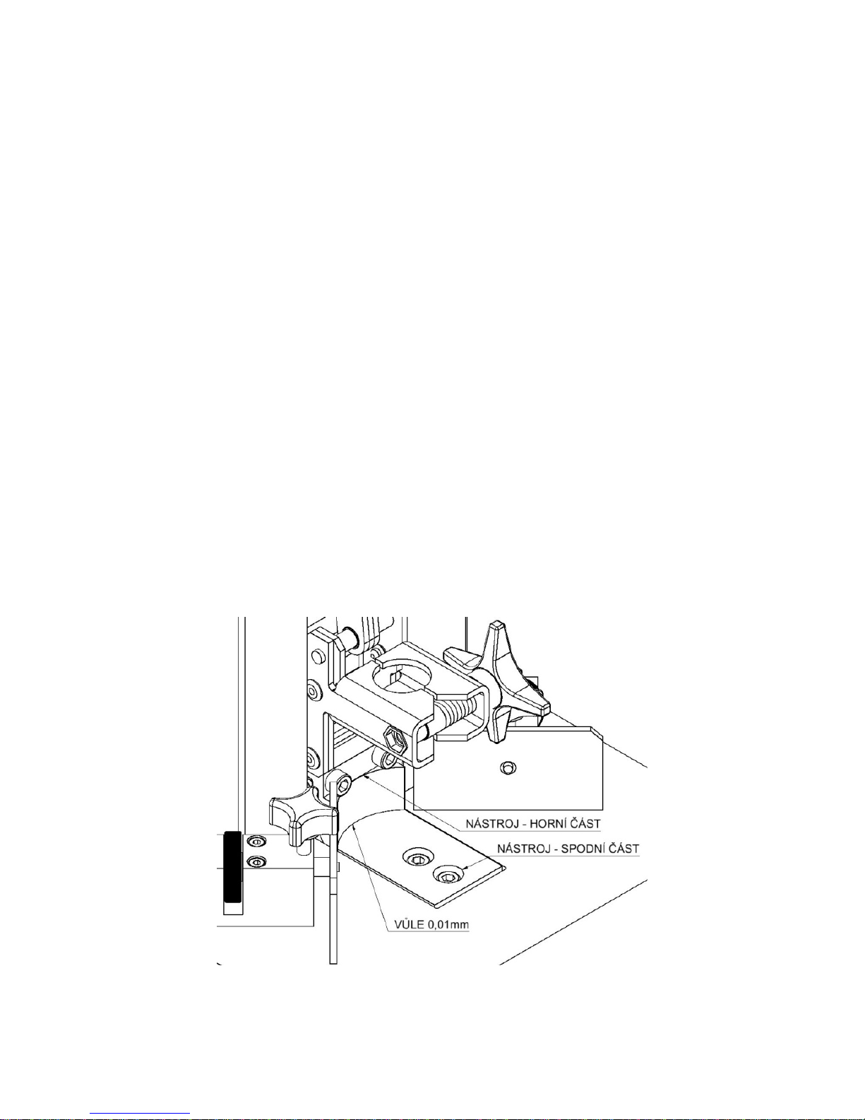
• Test t he shear without using force. During shearing there must not be any contact
between tools and the set clearance of the tools must be secured along the whole
cutting length of the tool. See the picture.
Vůle …… Clearance 0.01 mm
Nástroj – horní část … Tool – upper part
Nástroj – spodní část … Tool – lower part
Page 6

Operating Instructions | CCR 40
6
6.5 Paper cutting
The radius of the cut sheet must be symmetrical, its sharp edges must be free of frays in
the transition area between the sheet edge and the radius. Make sure that the whole stack
of sheets touches the stop, otherwise the rounding of all sheets cannot be guaranteed.
6.6 Removal of defects
• The cut sheet is frayed:
Check the blades for their sharpness as well as the clearance between both tools.
• The cut corner is not symmetrical and its edges are sharp:
Preset the stops co-linearly (parallel) to the lower tool’s edges.
• The machine does not run continuously, gets stuck and is sluggish:
Check the knife blades and the clearance between both tools. Check all moving
parts under the cover and the slide guide, or all slide bearings. The slide should be
practically free of radial play where it meets with the guide. The seizing of
antifriction bearings is not expected.
Note: During every new machine setting make sure that there is no collision or contact
between the upper and lower tools.
6.7 Cover dismounting
The cover can be dismounted only if work on the machine has been finished. When
resuming work the cover must be reattached and fastened.
7 Machine disposal
When the machine’s service life expires the machine can be liquidated together with
communal waste. First, the machine is dismantled, its metal, plastic, rubber or non-metal
parts are sorted and returned to appropriate salvage points for further recycling.
Machine parts are not made of dangerous materials. Therefore, their liquidation by a
specialized company is not required.
Waste c ategori es:
20 01 39 Plastics
20 01 40 Metals
 Loading...