


Cygnus 4+
Multi-Mode Ultrasonic Thickness Gauge
Operating Manual
Covers Gauge Model : M5-C4P
Doc No. M5-CYG4P-M-01_Iss5.doc
17 December 20 15

Cygnus 4+ Operating Manual
M5-CYG4P-M-01_Iss5.doc
QUALITY POLICY STATEMENT
Cygnus Instruments’ mission is to be a premier supplier of niche test and
measurement instruments. To achieve this we will:
Customers
• Be dedicated to customer satisfaction by listening to direct and
indirect feedback regarding our performance and product
requirements in general.
• Design state-of-the-art products that are robust, reliable, simple-touse and compliant with applicable industry and regulatory
requirements.
• Provide products and services that meet or exceed customer
expectations in terms of performance, reliability and safety.
Internal Systems
• Operate effective and safe working practices that comply with ISO
9001:2008 and EN ISO/IEC 80079-34 and other applicable regulatory
and statutory requirements.
• Provide adequate resources to ensure product and service quality is
maintained.
• Set, communicate and measure performance objectives and targets
to promote continual improvement.
• Ensure employees are competent and involved in improvement and
customer satisfaction matters.
Suppliers
• Use suppliers and subcontractors who share our passion for customer
satisfaction and who consistently perform reliably.
2

M5-CYG4P-M-01_Iss5.doc
Cygnus 4+ Operating Manual
Contents
1. Important Notice .............................................................. 8
2. Introduction ...................................................................... 9
Cygnus 4+ Thickness Gauge ....................................................9
Cygnus Instruments ............................................................. 10
Gauge Kit Contents ............................................................... 11
Basic Gauge Kit ................................................................... 11
Kit supplied with Single Element Probe .................................... 11
Kit supplied with Twin Element Probe ...................................... 11
3. Gauge Preparation .......................................................... 12
Fitting the Batteries ............................................................. 12
Connecting the Probe ........................................................... 13
Fitting the Neck Strap .......................................................... 14
4. Selecting the Right Probe ................................................ 15
Measuring Meta ls ................................................................. 15
Measurement Modes Explai ned and Compared ......................... 16
Multiple Echo Mode (ME) (Mode 3) ....................................... 16
Single Echo Mode (SE) (Mode 2) ......................................... 16
Echo-Echo Mode (EE) (Mode 3) ........................................... 17
Measuring Non-Steels .......................................................... 17
Measuring Non-Metals .......................................................... 18
Single Element Probes and Protective Membranes ..................... 18
Measuring Higher Tem peratures .......................................... 19
Summary of Cygnus Probes .................................................. 21
Twin Element probes ......................................................... 21
Single Element probes ....................................................... 21
The ‘Probe Type’ Code ....................................................... 22
5. Gauge Operation ............................................................. 23
Gauge Controls ................................................................... 23
Turning the Gauge On .......................................................... 24
Turning the Gauge Off .......................................................... 24
Automatic Power Off .......................................................... 24
Measurement S c reen V iews ................................................... 25
Status Information ............................................................... 26
Taking Thickness Measurements ............................................ 27
Zeroing the Probe (twin element probes) .............................. 27
Taking the Thickness Measurement...................................... 27
Echo Indicators in Multiple Echo Mode .................................. 28
3

Cygnus 4+ Operating Manual
M5-CYG4P-M-01_Iss5.doc
Measurement Stability Indication in SE & EE Modes ................ 29
Measuring Small Diameter Pipe & Tubes .................................. 30
Display Hold Function ........................................................... 30
Battery Life ......................................................................... 31
Battery Level .................................................................... 31
Low Battery Indication .......................................................... 32
6. Using the A-Scan Display ................................................ 33
Single Echo Mode ................................................................ 33
Measuring Over Corrosion Pits ............................................ 34
Echo-Echo Mode .................................................................. 35
Multiple Echo Mode .............................................................. 36
7. Calibration ...................................................................... 38
Why should I Calibrate my Thickness Gauge? ........................... 38
Calibration Options .............................................................. 39
Calibrating to a known thickness (Single or 1 Point) .................. 39
Two Point Calibration ........................................................... 41
Ladder Step Wedge ........................................................... 41
Two Point Calibration Procedure .......................................... 42
Probe Zero (twin element probes) .......................................... 44
Starting a Probe Zero from the Main Menu ............................ 45
Probe Zero Function .......................................................... 45
Setting the Velocity of Sound ................................................ 46
8. Gauge Setup ................................................................... 48
Menu Operation ................................................................... 48
Settings are Saved with the Probe Type .................................. 49
Inputting Numeric Values using the Navigation Keys ................. 50
Inputting Text using the Navigation Keys ................................ 50
Selecting the Probe Type ...................................................... 52
Automatic Probe Detection ................................................. 53
Measurement Un its .............................................................. 54
Resolution Setting ............................................................... 54
Limit Functions .................................................................... 55
Deep Coat Function (multiple ec ho mode) ............................... 58
9. Data Logging ................................................................... 61
Data Logging Features .......................................................... 61
Record Types ...................................................................... 62
Reference and Minimum Thicknesses ...................................... 62
Minimum Thickness Limit Alert ............................................ 62
Radia l Points ....................................................................... 62
4

M5-CYG4P-M-01_Iss5.doc
Cygnus 4+ Operating Manual
Measurement Co m m ent s ...................................................... 63
Loading Measurement Comments from a File ........................ 64
Grid Records ....................................................................... 64
Template Records ................................................................ 66
Data Logging Menu .............................................................. 66
Creating a new Record ......................................................... 66
Your Choices will be Saved for Next Time ............................. 68
Using a Template to Create a new Record................................ 69
User Field Input ................................................................ 69
Reviewing and Editing U s er Field Choices .............................. 69
Logging Thickness Measuremen t s ........................................... 70
Auto-Log Feature .............................................................. 71
Logging Obstructions and No-Readings ................................. 72
Changing Measurement Units whi l e D ata Logging................... 73
Re-taking the Last Measurement ............................................ 73
Stepping Backwards in the Record .......................................... 74
Adding Radial Points ............................................................ 75
Adding Measurement Comments ............................................ 77
Closing and Opening a Record ............................................... 78
Closing the Record ............................................................ 79
Opening a Record ............................................................. 79
Protecting a Record .............................................................. 80
Opening Protected Records ................................................. 82
Deleting Records ................................................................. 82
Deleting Individual Records ................................................ 83
Deleting All Records .......................................................... 84
Record Status ................................................................... 84
10. Data Logging Templates .............................................. 86
Templates .......................................................................... 86
Integrating with Microsoft Excel .......................................... 87
Measurement Points ............................................................. 87
User Fields ......................................................................... 88
User Field ‘List’ Type ......................................................... 88
11. Manual Gain Adjustment .............................................. 89
Manual Gain Mode ............................................................... 89
Turning on Manual Gain ..................................................... 89
Manual Gain Menu ............................................................ 90
Adjusting the Gain ............................................................ 91
Adjusting the Range .......................................................... 92
Measuring Below the Probes Minimum Thickness Specification . 93
5

Cygnus 4+ Operating Manual
M5-CYG4P-M-01_Iss5.doc
12. Setup Menu .................................................................. 94
A-Scan Range ..................................................................... 94
Automatic ........................................................................ 94
Manual ............................................................................ 94
Vibrate Feature ................................................................... 94
Brightness Setting ............................................................... 94
Power Off Setting ................................................................ 95
Auto-Log ............................................................................ 95
Comments .......................................................................... 95
Set Time and Set Date ......................................................... 96
Set Time and Set Date ......................................................... 96
13. General Points On Thickness Gauging .......................... 97
14. Troubleshooting ........................................................... 98
The Gauge will not Switch On ................................................ 98
Difficulty obtaining a Reading ................................................ 98
If Readings are Erratic or Unstable ......................................... 98
Tips for Optimising Battery Life .............................................. 98
15. Updating your Gauge ................................................. 100
Update Software ................................................................ 100
Gauge Firmware Files ......................................................... 100
16. Care and Servicing ..................................................... 101
Cleaning the Gauge ............................................................ 101
Batteries .......................................................................... 101
Environmental ................................................................... 101
Repairs ............................................................................ 101
Returning the Gauge for Servicing ........................................ 102
17. CygLink Computer Software ...................................... 103
Installing CygLink .............................................................. 104
Requirements ................................................................. 104
Upgrading ...................................................................... 104
Installing ....................................................................... 104
Connecting to the Gauge .................................................... 105
First time USB Connection ................................................ 105
Connecting the Gauge to CygLink f or t h e First Time ............. 106
Connecting to the Gauge Afterwards .................................. 107
Disconnecting from the Gauge .......................................... 107
Manual Connection Settings .............................................. 107
Status Bar ........................................................................ 107
Surveys ........................................................................... 108
6

M5-CYG4P-M-01_Iss5.doc
Cygnus 4+ Operating Manual
Creating a new Survey ..................................................... 108
Opening an Existing Survey .............................................. 109
Editing the Survey Info .................................................... 109
Managing the Survey ......................................................... 109
Sorting Survey Records ................................................... 109
Viewing Record Information .............................................. 110
Ref and Min Thickness ..................................................... 111
Protection State .............................................................. 112
Measurement Summary Stats ........................................... 112
Data Logger Records .......................................................... 112
Transferring Records from the Gauge ................................. 112
Viewing Thickness Measurements in a Record ...................... 114
Managing Measurements .................................................. 114
Viewing Measurement Information ..................................... 115
Adding Comments to Measurements .................................. 116
Viewing an A-Scan Graph ................................................. 117
Deleting all Records from the Gauge .................................. 118
Measurement Co m m ent List ................................................ 119
Material Veloc it y L is t .......................................................... 120
Creating a PDF Survey Report ............................................. 121
Exporting a Survey to a CSV File .......................................... 122
Templates ........................................................................ 123
Creating New Templates .................................................. 123
Editing Templates ........................................................... 124
Sending Templates to the Gauge ....................................... 127
Deleting Templates from the Gauge ................................... 128
Other Features .................................................................. 128
Setting the Time and Date on the Gauge ............................ 128
COM Port Numbers ............................................................ 128
Finding your COM Port Number ......................................... 128
18. Information ............................................................... 130
Technical Specifications ...................................................... 130
Table of Sound Velocities .................................................... 134
Reading Conversions ....................................................... 135
19. EU Declaration of Conformity ..................................... 136
20. Recycling and Disposal (EC Countries)....................... 137
21. Warranty Information ................................................ 138
22. Index ......................................................................... 139
7

Cygnus 4+ Operating Manual
M5-CYG4P-M-01_Iss5.doc
The following important information must be read and
gauges.
1. Important Notice
understood by all users of Cygnus ultrasonic thickness
The correct use of Cygnus ultrasonic thickness gauges requires
identification of the correct equipment for the specific application
coupled with an appropriately trained and qualified operato r o r
technician. The incorrect use of this equipment, along with its
incorrect calibration, can result in serious financial loss due to
damage to components, fac i l it ies, personal injury and even death.
Neither Cygnus Instruments nor any of its employees or
representatives can be held respo n si ble for improper use of this
equipment. Proper training, a complete understanding of ultrasonic
wave propagation, thorough reading of this manual, proper
transducer selection, correct zeroin g of the transducer, correct
sound velocity, correct use of th e appropriate test blocks, proper
cable length and proper couplant selection all play a factor in
successful ultrasonic thickness gauging. Of critical importance is
the process of complete and accurate calibration of the
instrument.
This manual will provide instructions in the set up and operation of
the thickness gauge. Additiona l factors that can affect the use of
ultrasonic equipment are beyond t h e scope of this manual and to
that end it is understood that the operator of this equipment is a
well-trained inspector qualified by either their own organisation or
another outside agency to the appropriate level of both theory and
practical application of ultrasonics .
Therefore Cygnus Instruments recommends t h at users of its
ultrasonic thickness gauges should be formally qualified to a
minimum of UT “Level 1” (ASNT or PCN) which will provide
approximately 40 hours of training.
8

M5-CYG4P-M-01_Iss5.doc
Cygnus 4+ Operating Manual
2. Introduction
Cygnus 4+ Thickness Gauge
The Cygnus 4+ Ultrasonic Thickness Gauge is a rugged,
handheld, battery-powered ins trument designed for high-reliability
thickness measurements in harsh environments using ultrasound.
It features a colour LCD display which can be easily read in most
light situations including sunlight.
The gauge can be used with a choice of Ultrasonic Probes, selected
to suit the material and thickness range to be measured.
The gauge can measure material thickness using three methods;
Single Echo, Echo-Echo or Multiple Echo. Echo-Echo an d Multiple
Echo allow measurements through su rface coatings which are
ignored. An A-Scan display provides the user with information that
can be used to visually verify the thickness measurem ent which
can displayed in Metric (mm) or Imperial (inch) units.
A Data Logging function can save thickness measurements and AScans in to a record file which can then be transferred to a
computer for analysis and report generation.
The gauge can easily be calibrated to a known thickness or to a
known Velocity of Sound.
The gauge is able to operate accurately over a wide range of
ambient temperatures and is environmentally sealed to IP67 for
use in wet conditions.
The gauge is a solid-state electronic instrument which, under
normal operating conditions, wil l give many years of active
service.
Although designed for ease of operation the first time user
should carefully read this manual to familiarise themselves
with the features of the Gauge.
9

Cygnus 4+ Operating Manual
M5-CYG4P-M-01_Iss5.doc
63 Jalan Pemimpin #05-01,
577219 Singapore.
Cygnus Instruments
Cygnus Instruments Limited, founded in 1983, were pioneers in
the development of the Digital Ult rasonic Multiple-Echo Technique
used for measurement through coatings. This has long been the
standard required to ensure that accurate measurements are
taken without the need to first zero the gauge or remove any
coatings.
Our philosophy is to work closely with ea ch of our customers to
provide a range of products spec i fically for each application.
Cygnus Ultrasonic Thickness Gauges are designed to be simple to
use and to withstand the harsh environments that they are
intended for. We have built up an enviable reputation with our
customers in over 45 countries around the world.
Cygnus House, 30 Prince of Wales Road,
Dorchester, Dorset DT1 1PW England.
Tel: +44 (0) 1305 265533 Fax: +44 (0) 1305 269960
www.cygnus-instruments.com sales@cygnus-instruments.com
CYGNUS Instruments Inc. CYGNUS Singapore (S) Pte. Ltd.
1993 Moreland Parkway, Suite 202.
Annapolis, Maryland 21401, USA.
Tel: +1 410 267 9771 Tel : +65 6252 5909
Fax: +1 410 268 2013 Fax : +65 6251 1318
www.cygnusinstruments.com www.cygnus-instruments.sg
sales@cygnusinstruments.com sales@cygnus-instruments.sg
Pemimpin Industrial Building.
10

M5-CYG4P-M-01_Iss5.doc
Cygnus 4+ Operating Manual
Gauge Kit Contents
Basic Gauge Kit
1. Cygnus 4+ Gauge
2. Operating Manual (in side pouch)
3. Neck Strap (in side pouch)
4. Accessory Pouch, containing; 3 x AA Batteries, Blue
Couplant Gel.
Kit supplied with Single Element Probe
1. Ultrasonic Probe
2. Moulded Probe Cable (in side pouch)
3. 15mm (or ½”) Steel Test Block
4. Spare Membranes
5. Membrane Key
6. Membrane Couplant
Kit supplied with Twin Element Probe
1. Ultrasonic Probe
2. Moulded Probe Cable (in side pouch)
3. Ladder Step Wedge, 4 Step.
11

Cygnus 4+ Operating Manual
M5-CYG4P-M-01_Iss5.doc
Press the bottom of the
The batteries are located
may leak out.
The gauge can be fitted with NiCad or NiMH rechargeable
batteries but this may alter the specified operating time.
3. Gauge Preparation
The gauge is supplied ready to use out of the box. Just insert the
batteries, connect the probe to th e gauge, turn on the power,
calibrate and you are ready to begin taking thickness
measurements.
Fitting the Batteries
The gauge requires 3 x AA/LR6/UM3 Ba t t eries. Cygnus supplies
and recommends Duracell Alkaline batteries. The batter ies are
located behind a cover on the rear of gauge. The hand strap can
be separated by a push-but t on buckle to gain access to the ba t t ery
cover. The battery cover is removed by pressing in with your
thumb the at the base to release the clip.
battery cover to release
the retaining clip and lift
up the battery cover.
underneath.
The gauge is protected
against electrical damage
from incorrect battery
insertion.
The battery compartment
itself is sealed to contain
any battery fluids that
12

M5-CYG4P-M-01_Iss5.doc
Cygnus 4+ Operating Manual
To avoid damage from leaking batteries always remove the
not be covered by the warranty.
The connector is
batteries if the gauge will be unused for any length of time.
If the batteries run flat they may leak acid into the battery
compartment and damage the electrical contacts. This would
Connecting the Probe
The Cygnus probe lead uses a c u stom made cable that offers
superior flexibility and resistance t o oi l s and ultraviolet light. The
cable will not stiffen after exposure to ultraviolet light.
The connector uses original Lemo connectors for reliability. The
twin connectors are over-mounded to form a tough housing that
will provide a long lasting probe cable
Depending on the type of probe supplied the probe end will have
either a BNC or single Lemo 00 connector.
orientated with a ‘pip’
and can only be plugged
in one-way around.
To release the connector
simply pull back on the
connector body. DO NOT
pull the cable.
13

Cygnus 4+ Operating Manual
M5-CYG4P-M-01_Iss5.doc
Wire loop fitted to the
The neck strap can then
Fitting the Neck Strap
The gauge is supplied with an adj u st able Neck Strap. The ends of
the neck strap clip onto two wire loops fitted to the gauge. These
wire loops are made from coated stainless steel.
gauge body.
Simply pass the loop
through the hole in the
gauge and back over the
other end.
be clipped on to the loops.
14

M5-CYG4P-M-01_Iss5.doc
Cygnus 4+ Operating Manual
The gauge must be set for the probe connected to it, see
Selecting the Probe Type on page 52.
Recommended..
Probe
Measurement Mode
Steels
Any
Non to
Moderate
1 mm+
S5A
Multiple Echo
Steels
Any
Non to
Moderate
2 mm+
S3C
Multiple Echo
Steels
Any
Non to
Moderate
3 mm+
S2C
Multiple Echo
Steels
Any
Non to
Moderate
3 mm+
(0.12”+)
S2D
Multiple Echo
Steels
Non
Non to
Heavy
1 mm+
T7A
Single Echo
Steels
Non
Non to
Heavy
2 mm+
T5B
Single Echo
Cast
Iron
Non
Non to
Moderate
3 mm+
T2C
Single Echo
When measuring in Multiple Echo mode the coating will be
ignored and just the metal thickness measured.
4. Selecting the Right Probe
The performance of any thicknes s gauge, and its ability to get a
reliable measurement depends on selecting the right ultrasonic
probe for the application and conditions. Cygnus gauges are
therefore offered with a selection of probes suitable for most
thickness gauging applications.
The following section helps you se lect t h e right probe for the
application.
Measuring Metals
Material Coating Corrosion Thickness
The table above shows that to be able to measure coated and uncoated steels with non to heavy corrosion ideally you will require
at least two probes, in almost all applications this will be a S2C
probe and a T5B probe.
15

Cygnus 4+ Operating Manual
M5-CYG4P-M-01_Iss5.doc
It is possible to use a Twin Elemen t ( T **) probe in Echo-
incorrect measurements.
Echo Mode to ignore thin paint coatings. However this
method does not have the ability to verify measurements
and without observing the A-Scan display it is possible to get
Measurement Modes Explained and Compared
Multiple Echo Mode (ME) (Mode 3)
Multiple Echo measurement mode is by far the most reliable and
quickest method for thickness measurements, because it works by
looking for three matched echoes it can verify the thickness
measurement is valid. This method has been used in all Cygnus
gauges since the late 1970s.
Multiple echo mode will ignore surface coatings (Through Coating
mode), there is no need to remove the paint to take a
measurement.
Also because it uses a single element (or single crystal) probe
there are no errors due to the V-path of the ultrasound beam
found in all twin element probes. This makes it simple to calibrate
– two point calibrations are not required.
However because it requires three echoes to take a measurement,
in heavily corroded steels there is often an insufficient number of
echoes so measurements may not be possible.
Single Echo Mode (SE) (Mode 2)
Single Echo measurement mod e is most useful on heavily corroded
metals where Multiple Echo fails. Because it only needs the first
return echo to take a measurement it performs well on virtually all
steel conditions.
However single echo mode will not ignore any surface coatings, so
if you measure through a coating it will give an incorrectly metal
thickness measurement . If the surface coating is very thin
(0.2mm / 0.01”) paint you can make an allowance for this error,
but thicker coatings introduce too much error to be practica l.
16

M5-CYG4P-M-01_Iss5.doc
Cygnus 4+ Operating Manual
Single echo measurements use a twin element (twin crystal)
probe, because there are two elements angled to a focal po int
there is a v-path error introduced. However this v-path error is
mostly corrected by the gauge, and furthermore by performing a
two point calibration.
Twin element probes requ ire “zeroing” at regular inter vals,
especially if the am b ient t em perature is changing.
To overcome some of the drawbacks of Single Echo measurements
the gauge has an A-Scan display that can be used to visually
verify the thickness measu rements are sensible and therefore
reliable. See section Using the A-Scan Display on page 33.
Echo-Echo Mode (EE) (Mode 3)
Echo-Echo mode uses a twin element probe, but measures
between the first two echoes. This method is intended to ignore
any thin surface coatings whilst still using a twin elem en t probe.
Echo-echo mode is not able to verify its measurements unlike
Multiple echo mode, therefo re it is liable to give incorre ct readings.
+
But as the Cygnus 4
gauge has an A-Scan display you can use
this to visually decide if the measurement given is correct.
Echo-echo mode must therefore b e used with caution, and only on
thin paint surface coatings (less than 0.5mm). It is recommended
a Single Echo measurement should also be made to help verify the
measurement makes sense (the Single Echo measurement should
always be slightly thicker due to the coating thickness).
Measuring Non-Steels
The gauge will measure the fo l lo wing non-steels;
• Aluminium alloys
• Copper and Brass alloys
• Titanium
Use the same rules as steels when selecting a suitable probe. The
gauge will ideally be re-calibrated to suit the metal being
17

Cygnus 4+ Operating Manual
M5-CYG4P-M-01_Iss5.doc
measured, or the standard velocity of sound for that material
would be entered into the gauge.
Measuring Non-Metals
You can measure certain types of plastics with the gauge using a
twin element probe and the gauge set to Single Echo
measurement mode. Generally the harder the plastic the better,
soft materials like rubber or TPEs tend to absorb too much
ultrasound so only thin samples can be measured.
Engineering plastics like Acetal, Tufset (Polyurethane), Nylon and
High-density polyethylene (HDPE) can be measured successfully.
Rotationally Moulded pa r ts can generally be measured
successfully.
• You must use Single Echo mode to measure plastics.
• You must generally use a low frequency probe (i.e. T2C) to
measure plastics, but this will d epend on the properties of the
material.
• Any material with a closed-cell construction cannot be
measured.
• Any material with internal voi ds, air bubbles or honeycomb
cannot be measured.
Typically these materials cannot be measured with the gauge;
• Concrete
• Wood
• Thermal insu la t ion mater ials
• Foams
• Composites
Single Element Probes and Protective Mem branes
All Cygnus single element probes h ave a soft face and are
therefore fitt ed with a Polyurethane Membrane which provides
18

M5-CYG4P-M-01_Iss5.doc
Cygnus 4+ Operating Manual
Check the membrane regular ly as it is important the
membrane is changed as soon as it shows any signs of wear.
Probe Body
Locking Ring
Polyurethane Membrane
Knurled Ring
better contact on rough surfa ces and protects the probe face from
wear, prolonging the life of the probe.
Single Element Probe Membrane Parts.
Single Element Probe Membrane Locking Key
Measuring Higher Temperatures
The polyurethane membranes fitted to the s ingle e lement probes
are suitable for measuring surface temperatures up to 75°C. For
measuring higher temperatures Teflon Membranes are available
and suitable for surface temperat ures up to 150°C. Contact
Cygnus instruments to order Teflon membranes.
19

Cygnus 4+ Operating Manual
M5-CYG4P-M-01_Iss5.doc
1.
Unscrew the Knurled Ring from the
2.
Use the Membrane Key to unscrew
discarded.
3.
Place a new membran e into th e end
4.
Screw the Locking Ring back inside
5.
Place a few drops of Membrane
6.
Screw the Knurled Ring back onto
Knurled Ring down.
7.
You should see the membrane has
a very thin film of couplant between
bubbles.
Changing the Protective Membrane on Single element Probes
end of the Probe.
the Locking Ring from inside the
Knurled Ring. The old membrane
can then be removed and
of the Knurled Ring ensuring it
locates in the groove.
the Knurled Ring and tighten with
the Membrane K ey.
Couplant on to the probe face.
the probe. Use your thumb to
squeeze the couplant from under
the membrane as you tighten the
itself and the probe face with no air
20

M5-CYG4P-M-01_Iss5.doc
Cygnus 4+ Operating Manual
T2C
12mm
2 MHz
3 to 250 mm
0.12 to 10”
Attenuative materials
Cast irons, plastics
T5B
8mm
5 MHz
2 to 200 mm
0.08 to 8”
General purpose
Most metals
T7A
5mm
7.5 MHz
1 to 50 mm
0.04 to 2”
Thin metals
S2C
13mm
2.25 MHz
3 to 250 mm
General purpose probe suitable
Coated metals
S2D
19mm
2.25 MHz
3 to 250 mm
As S2C but has longer focal
on thicker materials
S3C
13mm
3.5 MHz
2 to 150 mm
Coated metals
S5C
13mm
5.0 MHz
1 to 50 mm
Coated metals
S5A
6mm
5.0 MHz
1 to 50 mm
Small diameter tubes
Coated metals
Summary of Cygnus Probes
Twin Element probes
Probe
Type
Size Frequency
Single Element probes
Probe
Type
Size Frequency
Range in
Steel
(SE Mode)
Range in
Steel
Typical Uses
Typical Uses
for most applications that can
use Multiple Echo
measurement.
0.75”
0.12 to 10”
point (33 mm) and narrower
beam so may perform better
Thin metals
21

Cygnus 4+ Operating Manual
M5-CYG4P-M-01_Iss5.doc
S
2
C
Size
D 19mm
The ‘Probe Type’ Code
Single or Twin
Crystal
Frequency in MHz
A 6mm
B 8mm
C 13mm
22

M5-CYG4P-M-01_Iss5.doc
Cygnus 4+ Operating Manual
Probe
Power
Select
Menu
Navigation
5. Gauge Operation
Gauge Controls
End view of gauge
Connections
Keys
Key
Key
Keys
Front view of gauge
23

Cygnus 4+ Operating Manual
M5-CYG4P-M-01_Iss5.doc
1.
Press the Power key
2.
Cygnus Instruments Logo is
displayed
3.
The gauge details are displayed;
4.
The gauge is ready to use
1.
Press & Hold the Power key,
2.
The display shows ‘power-off’ and
Turning the Gauge On
Model
Serial Number
Version Number
Run Time
Turning the Gauge Off
the gauge turns off.
Automatic Power Off
By default the gauge will turn off automatically after 5 minutes of
in activity.
24

M5-CYG4P-M-01_Iss5.doc
Cygnus 4+ Operating Manual
1.
Use the Left and Right
2.
Basic Screen
3.
A-Scan Screen
Taking thickness measurements or accessing the menu will reset
the activity timer back to zero.
You can change the activity time value the Setup menu, see Power
Off Setting on page 95.
Measurement Screen Views
The gauge has three measurement screens that can be quickly
changed using the left and right navigation keys. These screens
offer three views to suit the situation.
navigation keys to move
between the th ree screens
Just shows a large thickness
measurement value.
Show the thickness
measurement and a live A-Scan
display of the ultrasound signals
received.
25

Cygnus 4+ Operating Manual
M5-CYG4P-M-01_Iss5.doc
4.
Data Logging Screen
Battery
Level
Measurement
Mode
Deep Coat
Function
Velocity, or
‘Calibrated’
Probe
Type
When data logging is active this
screen shows details of logged
measurements.
Status Information
At the top of the display is an area that shows information about
the gauge’s status;
• Battery Level
• Velocity of Sound value / Calibra tion Status
• Probe Type
• Measurement Mo de
• Deep Coat Function
Probe Type; when the probe is connected the background colour is
green, when disconnected it is grey.
Measurement Mo d es;
26
ME Multiple Echo
EE Echo-echo
SE Single Echo

M5-CYG4P-M-01_Iss5.doc
Cygnus 4+ Operating Manual
It is recommended to frequently perform a Probe Zero
especially if conditions such as temperature are changing.
1.
Remove all scale, rust, dirt or loose
2.
Apply ultrasonic couplant to the test
3.
Place the probe-face on the clean,
4.
The gauge will display a thickness
Multiple Echo mode).
Taking Thickness Measurements
Taking ultrasonic thickness measurements is a straight forwar d
process that involves first making sure the surface is clean and
prepared, applying an ultrasonic couplant gel then placing the
probe on the surface and observing the display for the
measurement.
Zeroing the Probe (twin element probes)
When a twin element probe is connected to the gauge (and the
gauge is set to the correct probe) you must first perform a Probe
Zero before you can begin takin g measurements. For instructions
see Probe Zero Function on page 45.
Taking the Thickness Measurement
coatings and brush the test area clean.
surface.
lubricated test surface and make firm
contact applying gentle pressure.
measurement.
(Or an indication of Echo Strength if no
valid measurement has been found in
27

Cygnus 4+ Operating Manual
M5-CYG4P-M-01_Iss5.doc
1.
1 Bar Flashing:
2.
1 steady + 1 Bar Flashing:
3.
2 steady + 1 Bar Flashing:
4.
3 steady + 1 Bar Flashing:
Echo Indicators in Multiple Echo Mode
Should the gauge be unable to detect a stable multiple echo signal
it displays an Echo indication to help the operator locate a suitable
position.
No echoes detected
Only 1 echo detected
Only 2 echoes detected
3 echoes detected but they are
not matched
28

M5-CYG4P-M-01_Iss5.doc
Cygnus 4+ Operating Manual
1.
Initial measurements will be
2.
If the measurement remains stable
To help obtain a multiple echo reading the operator should
continue to move the probe around to locate a suitable reflector ,
using a slight rocking motion.
Measurement Stability Indication in SE & EE Modes
To help indicate when a Single Echo or Echo-Echo measure ment is
stable – and thus probably reliable – the gauge changes the
thickness measurement number colour from Red to Green when
the measurement has been stable for 2 consecutive seconds.
When measuring using Single Echo or Ech o-Echo mode once you
have a measurement keep the p robe still and wait for the gauge to
signal a “stable reading”.
If the ultrasound signal is poor or erratic then the thickness value
may remain red – thus indicating the measurement may not be
reliable.
displayed as red numbers.
for 2 consecutive seconds then the
measurement will change to
green.
Stable is defined as; the thickness measurement changing no
more than + or - the Resolution setting.
Example.
29

Cygnus 4+ Operating Manual
M5-CYG4P-M-01_Iss5.doc
The dividing line on the face of the probe should be at
1.
A thickness measurement is
Pipe
Probe Face
Probe Face Division is at
The Resolution is set to 0.05mm, therefor the thickness
measurement must not change by more than +0.05mm or
-0.05mm for 2 seconds or more to be “stable”.
Measuring Small Diameter Pipe & Tubes
When measuring small diameter pipe and tubes with a twin
element probe, 75mm (3”) or u n der, you must ensure the face of
the probe is correctly aligned to th e curvature of the pipe
otherwise measurements may be inaccurate.
right angles to the length of the pipe.
Display Hold Function
The thickness measurement can be ‘Held’ or frozen by simply
pressing the X/Cancel key while in any measurement screen.
displayed
right angles to the pipe
30

M5-CYG4P-M-01_Iss5.doc
Cygnus 4+ Operating Manual
2.
Press the X/Cancel key to hold the
3.
Press the X/Cancel key to un-hold
Battery almost full
thickness measurement.
The measurement value now has
a light blue border to indicate it’s
held or froze.
the thickness measurement.
Battery Life
The gauge will operate continuously for approximately 10 hrs
when fitted with Duracell Alkaline 1500 mA/hr batteries.
Battery Level
A battery level graphic is displayed at the top left position of the
display (arrowed);
31

Cygnus 4+ Operating Manual
M5-CYG4P-M-01_Iss5.doc
Battery about 1/2 full
Battery low
Low battery indication
Flat Battery message
Low Battery Indication
The gauge will perio dically f la sh a r ed Lo w Battery warning sign
when the batteries have approximately 1 hour of use remaining.
When the batteries are exhausted the gauge will display a Flat
Battery message for 5 seconds then turn off automatically.
32

M5-CYG4P-M-01_Iss5.doc
Cygnus 4+ Operating Manual
This A-Scan shows a good clear
Good Signal
6. Using the A-Scan Display
To help ensure reliable measurements in Single Echo and EchoEcho measurements the gauge has an A-Scan display that can be
used to visually verify the thickn ess measurements are sensible
and therefore reliable. With some practice any user can quickly
and easily use the A-Scan to decide if the measurement is correct.
To view the A-Scan display use the Left and Right navigation keys
to switch between the measurement screen views (see
Measurement S c reen V iews on page 25).
The A-Scan display shows the actual ultrasound echo pulses as
received by the gauge; these echo pulses are used by the gauge
to determine the thickness measurement if possible.
The gauge works by generating a short pulse of ultrasound that is
coupled into the object you are measuring. This pulse then travels
through the object and is reflected back to the probe as an echo
by either the back-wall of the object and/or any internal flaws or
corrosion pits. When the echo pulse hits the probe surface a signal
is received by the gauge, this signal is shown on the A-scan
display as an echo peak, the taller the peak the stringer the signal.
Single Echo Mode
The A-Scan display is very useful when measuring in Single Echo
modes, as there is no verification of the thickness measurement
observing the A-Scan display will help the user verify the echo
detected is the correct one – the back-wall echo.
ultrasound signal.
There is a well-defined back-wall echo
and the arrow is correctly placed.
The measurement value of 1 2.7 is stable
when green in colour.
33

Cygnus 4+ Operating Manual
M5-CYG4P-M-01_Iss5.doc
This A-Scan shows a very weak
fails then try another position.
You should be careful not to attempt t o t ake a single echo
ultrasound signal.
There is no clear correct back-wall echo
and the gauge is unable to determ in e a
thickness measurement.
You should try moving the probe to find
a better reflector, first rotate the probe
to see if that gets a measurement, if that
Measuring Over Corrosion Pits
thickness measurement when there is a void or corrosion pit
Weak Signal
directly underneath the probe face as the gauge may
incorrectly measure the depth of the couplant.
Large Corrosion Pit s.
34

M5-CYG4P-M-01_Iss5.doc
Cygnus 4+ Operating Manual
This A-Scan shows an incorrect
Corroded Metal
Couplant
Probe
Avoid Measuring Directly Over Corrosion Pits.
Pit
The A-Scan display can assist you - you will see an unclear
ultrasound signal with unclear back wall reflections.
measurement that may be from
measuring couplant inside a pit .
Echo-Echo Mode
Like Single Echo mode the A-Scan can be very useful when taking
measurement through coatin g u sing Echo-Echo mode. Echo-Echo
mode measures thickness by measuring the time between two
consecutive echo signals, in ideal conditions this is a good reliable
method of thickness measurement thorough coating, but when
corrosion starts to degrade the echoes the gauge could measure
between two incorrect echoes and give a wrong reading. Here the
35

Cygnus 4+ Operating Manual
M5-CYG4P-M-01_Iss5.doc
This A-Scan shows an unclear Echo-Echo
then another location.
The gauge measures between the se two echo
A-Scan can assist, by observing the echo signals you can decide of
the thickness measurement given makes sense and is reliable.
signals to calculate the thickness. This is a good
clear signal so the measurement is reliable.
The two purple arrows mark th e points the gauge
has measured between.
measurement.
The echoes are scattered and although
the gauge has given a thickness
measurement of 5.5mm it ma y no t be
accurate. Try first rotating the probe
Multiple Echo Mode
Although Multiple Echo mode has the benefit if providing “echo
matched” verified thickness measurements and can be used
reliably without observing the A-S can display, the A-Scan display
can sometimes help where measurements are difficult or suspect.
36

M5-CYG4P-M-01_Iss5.doc
Cygnus 4+ Operating Manual
This A-Scan shows a good Multiple-Echo
This A-Scan shows a Multiple-Echo
This A-Scan shows no Multiple-Echo
SE or EE mode.
measurement on a new steel sample.
The echo signals are distinct a n d clear.
The three purple arrows mark t he
positions the gauge used for the
thickness measurement.
measurement from a corroded steel
sample.
The three echo signals have been picked
out ok, but there is less clarity ar ou n d
echo 2 and 3.
measurement.
The echo signals are all over th e display,
there are no distinct echoes for the
gauge to pick out. You should move the
probe to another location, or t ry using
37

Cygnus 4+ Operating Manual
M5-CYG4P-M-01_Iss5.doc
7. Calibration
Why should I Calibrate my Thickness Gauge?
Ultrasonic thickness gauges measure time in order to measure the
thickness of the material being tested. It relies on the principal
that sound travels through a material at a constant velocity or
speed. If you can accurately measure the time it takes to travel
through a material and you know its velocity then you can
calculate its thickness;
Thickness = time x velocity
2
Modern thickness gauge are easily capable of measuring time
accurately to 10 Nano seconds (0.000,000,01 second) so this is
considered to be more than sufficiently accurate.
This means the accuracy of any thickness gauge measurement
relies principally on the velocity being correct for the material
being measured.
There are tables listing the velocity of most common metals and
materials, but these velocities are only “typical” values. For
example Mild Steel has a typical velocity of 5920 m/s – but in
practice when measuring a variety of mild steel samples the
velocity can range anywhere from 5860 to 5980 m/s.
This means if you want to achi eve the most accurate thickness
measurements you must calibrate your thickness gauge to a
sample of the same material you will be testing – and a sample
that you can accurately measure the thickness of with a Vernier or
micrometer.
Your measurements are only as good as your calibration
Instructions for calibrating the gauge can be found on page 39
onwards.
38

M5-CYG4P-M-01_Iss5.doc
Cygnus 4+ Operating Manual
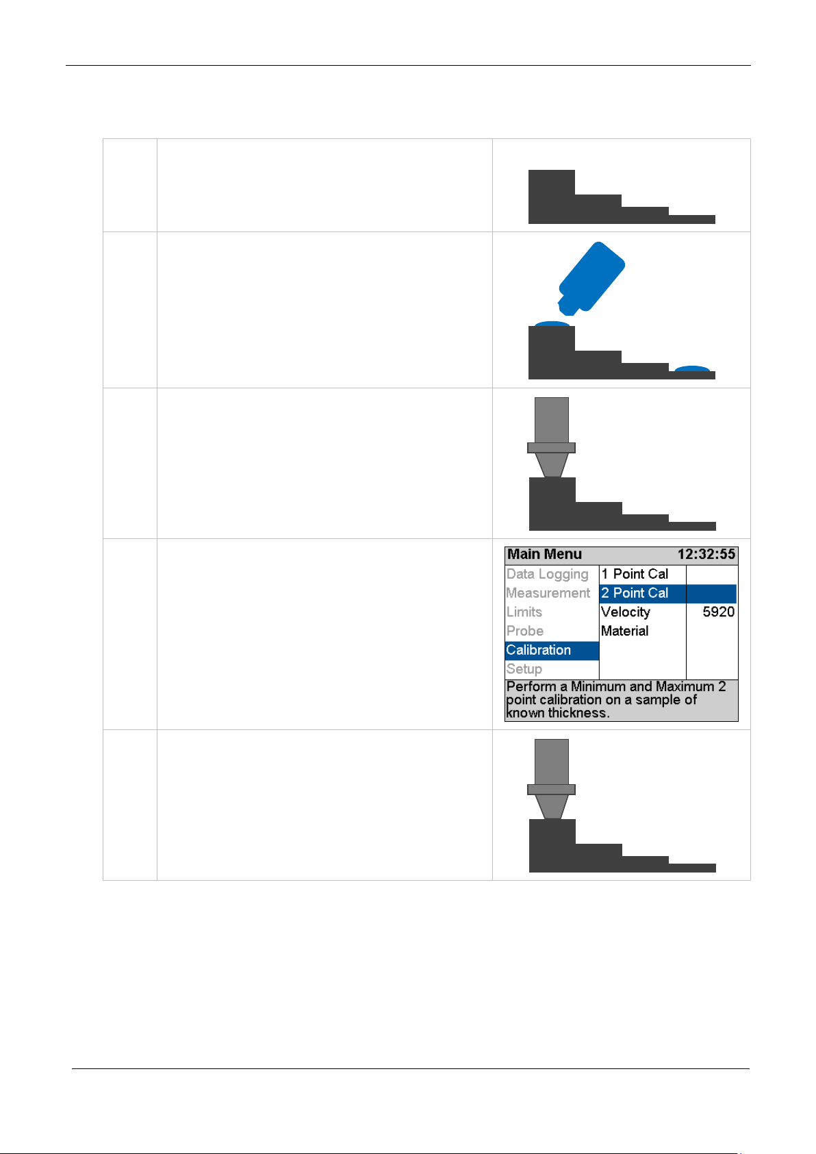
1.
Accurately measure the
25.40
Calibration Options
The Gauge is supplied tested and calibrated. The Gauge will have
been calibrated to measure thickness through steel (grade
S355JO) with a velocity of sound of 5920 m/s.
Either a 15mm or 1/2” Test Block is supplied with the kit so the
Gauge can be quickly checked for correct operation. Note, this test
block is not intended to be used for calibration of the Gauge.
The best way to calibrate the Gauge is to Calibrate using a
Known Thickness using a sample of the material you intend to
measure. This method determines the velocity of sound for
the material sample, which will always be more accurate than
using a ‘general’ velocity value. For calibration instructions
see page 39.
If there is no test sample available the Gauge can be calibrated by
Setting the Velocity of Sound directly. A table on page 134
at the
back of this manual lists common ma t erials and their velocity of
sound value. For calibration instructions see page
40.
A third method is to leave the Gauge set to its factory-preset value
for Steel [5920 m/s or 0.2332 in/us], and then use a Conversion
Factor from the table of velocities on page 134
.
Calibrating to a known thickness (Single or 1 Point)
This method of calibrating the gauge is more accurate than using a
standard velocity value as the gauge calculates the velocity of
sound for the sample material.
You can use this calibration method for all measurement modes.
thickness of your sample
material.
mm
39

Cygnus 4+ Operating Manual
M5-CYG4P-M-01_Iss5.doc
2.
Place the Probe on the sample
3.
Access the Menu and scroll down
4.
While holding the probe firmly
5.
...use the Up and Down keys to
6.
When done press the OK/Select
Or press the X/Cancel key to exit
and verify the gauge can get a
thickness value.
to the ‘Calibration’ group. Then
scroll right to the ‘1 Point Cal’
item.
Press the Ok/Select key to open
the ‘1 Point Cal’ function
on the sample and while a
steady thickness measurement
is displayed..
adjust the thickness to the
required value.
key to save the calibration. A
Calibration Saved message wil l
be shown.
without saving the calibration.
When a Calibration has been made a ‘1PC’ indictor is displayed at
the top of the measurement screen in the status area (1PC =
Single Point Calibration).
40

M5-CYG4P-M-01_Iss5.doc
Cygnus 4+ Operating Manual
To achieve maximum accuracy in Single Echo mode
Typically a Ladder Step Wedge is
‘1PC’ Indicator
Two Point Calibration
The Two Point Calibration option is only available in Single Echo
and Echo-Echo modes.
Two point calibration allows the gauge to be calibrated against two
reference thicknesses of the same material, one at the minimum
(thin) thickness range the other at the maximum (thick) thickness
range.
you must perform a Two Point Calibration – your
measurement is only as good as your calibration.
When performing a two point calibration both sample thicknesses
should be made from the same material. The temperature of the
sample material should be the c lo se to t he temperature of the
material to be meas ur ed .
The gauge will automatically compensate for v-path error in
addition to either single or two point calibrations.
Ladder Step Wedge
used to calibrate the probe and
gauge for Steel. The ladder step
wedge has 4 or 5 different
thicknesses typically ranging from
2.5 mm to 20.0 mm. You would
typically choose to calibrate using
the 2.5 and 20 mm thicknesses.
Ladder Step Wedges
41
Cygnus 4+ Operating Manual
M5-CYG4P-M-01_Iss5.doc
1.
Assuming you have a step
2.
Wipe clean the step wedge then
3.
Place the Probe on the sample
4.
Access the Menu and scroll down
5.
Start with the Thick sample –
20.00
2.50
Two Point Calibration Procedure
wedge of known thicknesses
add some fresh couplant to the
step wedge
and verify the gauge can get a
thickness value.
to the ‘Calibration’ group. Then
scroll right to the ‘2 Point Cal’
item.
Press the Ok/Select key to open
the ‘2 Point Cal’ screen
Maximum thickness.
42

M5-CYG4P-M-01_Iss5.doc
Cygnus 4+ Operating Manual
6.
While holding the probe firmly
7.
When the correct measurement
key
8.
Next measure the Thin sample –
9.
While holding the probe firmly
10.
When the correct measurement
key
on the thick sample and while a
steady thickness measurement
is displayed..
...use the Up and Down Select
keys to adjust the thickness to
the required value.
is displayed press the OK/Select
Minimum thickness.
on the thin sample and while a
steady thickness measurement
is displayed..
...use the Up and Down Select
keys to adjust the thickness to
the required value.
is displayed press the OK/Select
43

Cygnus 4+ Operating Manual
M5-CYG4P-M-01_Iss5.doc
11.
The 3rd screen lets you check the
12.
When done press the OK/Select
Or press the X/Cancel key to exit
It is recommended to frequently perform a Probe Zero
calibration is correct my
checking a few different
measurements on the step
wedge.
key to save the calibration. A
Calibration Saved message wil l
be shown.
without saving the calibration.
Probe Zero (twin element probes)
Twin element probes must be zeroed to compensate for any wear
or operating temperature changes. The gauge will always perform
a Probe Zero when first turned on or when a twin element probe is
connected.
If the probe gets significantly war mer during use this can cause a
shift in the zero position and thus introduce small errors in the
thickness measurement. Typically a 20° C change in te mperature
the measurements can shift by 0 .1 mm.
especially if conditions such as temperature are
changing.
See also Zeroing the Probe (twin element probes) on page 27.
44

M5-CYG4P-M-01_Iss5.doc
Cygnus 4+ Operating Manual
1.
Access the Menu and scroll down
2.
Display shows the Zero Probe
3.
Press the OK/Select key to
Starting a Probe Zero from the Main Menu
to the ‘Probe’ group. Then scroll
right to the ‘Zero’ item.
Press the Ok/Select key to start
the ‘Zero’ function
Probe Zero Function
message.
Important - Wipe any couplant
from the probe face
proceed
The gauge measures the probe
zero point…
..this takes about 2 seconds.
45

Cygnus 4+ Operating Manual
M5-CYG4P-M-01_Iss5.doc
4.
If the Probe Zero fails a message
Probe Zero process.
If you perform a Calibration the Velocity of Sound will be set
will be d is p layed.
• Check the probe has not
been unplugged or the
cable is damaged/faulty.
• The probe face must be
clean and in the air.
• Are you using a non-
Cygnus probe?
You must un-plug the probe,
then plug it back in to re-try the
Setting the Velocity of Sound
The gauge uses the Velocity of Sound value to calculate the
material thickness value. It is therefore i mportant the velocity
value is set correctly for the mat erial being measured.
for you during the calibration – so you don’t need to adjust it
afterwards.
You can manually set the velocity of sound value if required;
normally you would do this if;
• You can’t perform a cal ibration
• You want to use the same velocity setting as last time
• You want to use a velocity from a material list
A list of velocity of sound values for common material can be
found on page 134.
46

M5-CYG4P-M-01_Iss5.doc
Cygnus 4+ Operating Manual
1.
Access the Menu and scroll down
3.
If there has been a previous
4.
Use the Up and Down keys to
5.
When done press the OK/Select
Or press the X/Cancel key to exit
without saving.
to the ‘Calibration’ group. Then
scroll right and select ‘Velocity’.
Press the Ok/Select key to open
the ‘Velocity’’ function
Calibration a message will warn
that changing the velocity w i l l
alter the calibration;
Press the OK/Select key to
continue, or X/Cancel to abort.
adjust the velocity value as
required
Use the Left and Right keys to
highlight the digit to change.
key to save the changes.
When the velocity has been manually set the value is displayed at
the top of the measurement screen in the status area.
Velocity of Sound value ‘5920 m/s’
47

Cygnus 4+ Operating Manual
M5-CYG4P-M-01_Iss5.doc
1.
Press the Menu key,
2.
the Main Menu is displayed
3.
Use the four Navigation keys to
4.
Use the Up and Down keys to
5.
Press the Right key to move to
8. Gauge Setup
Menu Operation
scroll around the Main Menu
select a group in the left
column..
the items in that group in the
right column.
Then use the Up and Down keys
to select from the right column
48

M5-CYG4P-M-01_Iss5.doc
Cygnus 4+ Operating Manual
6.
If you want to change or select
button
7.
Then use the Navigation keys to
8.
Press the green Ok/Select key to
9.
Or press the red X/Cancel key to
6.
Press the Left key to go back to
12.
To exit the menu press the Menu
the item currently displayed
simply press the green Ok/Select
highlight the required setting or
option
save your choice
abort
the main group if you want to
make another selection
or red X/Cancel key once.
Settings are Saved with the Probe Type
Certain gauge settings are saved against the probe type. This
allows each probe type to have different settings that will be
recalled when that pro be is re-connected and the probe type is
correctly set. The following settings are saved with each probe
type;
49

Cygnus 4+ Operating Manual
M5-CYG4P-M-01_Iss5.doc
1.
The units digit is highlighted.
2.
Pressing the Left key will move
this value only.
3.
Pressing the Left key will move
change this value only.
4.
Pressing the Left key will move
change this value only.
• Units
• Resolution
• Velocity of sound
• Calibration
• Deep Coat
Inputting Numeric Values using the Navigation Keys
Some menu functions require the user to input a numeric value
using the navigation keys. This is done ‘digit’ as a time, using the
Left and Right keys to select the digit, then the Up and Down keys
to change the highlighted digits va lu e.
Pressing Up or Down will change
the units value only.
the highlight to the tens digit.
Pressing Up or Down will change
the highlight to the hundreds
digit. Pressing Up or Down will
the highlight to the thousands
digit. Pressing Up or Down will
Inputting Text using the Navigatio n Keys
Some functions may require alphanumeric text to be input into the
gauge. This is done using a special alphanumeric entry screen and
the navigation keys.
50

M5-CYG4P-M-01_Iss5.doc
Cygnus 4+ Operating Manual
1.
The screen is divided into ‘virtual’
enter the character or perfor m t he
function.
2.
To enter the word CYGNUS you
3.
There are ‘keys’ for
4.
When you have entered your
keys like a QWERTY keyboard.
You move the Blue highlight
around using the 4 navigation
keys.
Then press the Ok/Select key to
would move the blue highlight
from Ok to ‘C’ then press the
Ok/Select key, then move to the
‘Y’…
Delete last = Del
Space = Spc
Clear all = Clr
Move = ◄ ►
Toggle case = ▲
word just move the highlight to
the green ‘Ok’ at the bottom and
press the Ok/Select key.
51

Cygnus 4+ Operating Manual
M5-CYG4P-M-01_Iss5.doc
The Probe Type must be set to match the probe connected to
measure accurately if at all.
1.
Access the Menu and scroll down
Selecting the Probe Type
the gauge. If the wrong probe is s elected the gauge will not
The gauge can Auto Detect certain types of probes when they ar e
first connected to the gauge, or you can manually select the probe
from a list.
These probes can be Auto Detected; T2C, T5B, T7A & S2C
These probes must be selected manually; S3C, S5A & S5C
The Probe Type is displayed is displayed at the top of the
measurement screen in the status area. When a probe is
connected the background is green. When no probe is detected the
background is grey.
S2C Probe Selected and Connected
S2C Probe Selected but NOT Connected
to the ‘Probe’ group. Then scroll
right and select ‘Probe Type’.
Press the Ok/Select key to open
the ‘Probe Type’ function
52

M5-CYG4P-M-01_Iss5.doc
Cygnus 4+ Operating Manual
2.
Use the Up and Down keys to
3.
Press the OK/Select key to save.
Or press the X/Cancel key to exit
Remember settings and calibrat i on is saved with each probe
calibrate each time.
select the Probe Ty pe req u ire d
without saving.
type. So if you change the probe t ype you may find a setting
has changed – this is normal.
The reason settings are saved with each probe type is so you
can swap probes during a survey without having to re-
Automatic Probe Detection
The Automatic Probe Detection feature works by listening to how
the probe behaves when it is first plugged in. For that reason the
probe MUST BE in the air and not coupled to a surface when
plugging in or turning on the gauge.
When Probe Type set to Auto and a probe is connected the gauge
will try and determine the probe type – this will be displayed at
the top of the screen on the ri ght .
S2C Probe Selected and Connected
Observe this probe type displayed and check it matches the probe
connected to the gauge.
53

Cygnus 4+ Operating Manual
M5-CYG4P-M-01_Iss5.doc
1.
Access the Menu and scroll down
2.
Use the Up and Down keys to
4.
Press the OK/Select key to save.
Or press the X/Cancel key to exit
If the gauge fails to correct ly det ect the probe type then you must
select if manually from the list of probes. See Selecting the Probe
Type on page 52.
Measurement Units
The Gauge can display thickness measurements in either Metric
(mm) or Imper ial (inch). Changing the measurement units will not
affect the calibration.
to the ‘Measurement’ group .
Then scroll right and select
‘Units’.
Press the Ok/Select key to open
the ‘Units’ function
switch from mm to Inch
without saving.
Resolution Setting
The gauge can display thickness measurements in three resolution
settings:
• 0.1 mm 0.005 inch All Modes
54
• 0.05 mm 0.002 inch All Modes
• 0.01 mm 0.001 inch SE and EE Modes only

M5-CYG4P-M-01_Iss5.doc
Cygnus 4+ Operating Manual
1.
Access the Menu and scroll down
2.
Use the Up and Down keys to
3.
Press the OK/Select key to save.
Or press the X/Cancel key to exit
without saving.
For general metal corrosion measurement the 0.1 mm
resolution setting is recommended.
To change the Resolution setting:
to the ‘Measurement’ group .
Then scroll right and select
‘Resolution’.
Press the Ok/Select key to open
the ‘Resolution’ function
select the required Resolution
Limit Functions
The gauge has a Limit function t hat can be used to;
• Give visual indication of measurements between minimum,
reference and maximum limits.
• Vibrate Alert the operator if measurements are o utside the
minimum or maximum limits
55

Cygnus 4+ Operating Manual
M5-CYG4P-M-01_Iss5.doc
Limits are setup;
bar positioned at the Reference point.
The Limit function can be turne d ON or OFF as required and the
Vibrate Alert can be enabled as required.
There are three Limit measurement values you can set;
• Minimum Limit – this is the lowest t h i ckness measurement,
measurements under this value will cause an Alert
• Reference Limit – this is the ‘correct’ thickness value, or
when corrosion monitoring this is usually set to the thickness
of the steel/material when it was new.
• Maximum Limit – this is the highest thickness measu rement,
measurements over this value will cause an Alert. This limit is
optional and can be set to zero.
When Limits are enabled the measurement screen displays a
horizontal bar-graph showing the limits and the current
measurement in relation to these limits. The colour of the bar also
changes from light green to dark green to red as the measurement
moves from the reference value to the minimum or maximum
limits.
Thickness Measurement = Reference = Light Green Bar.
Limit Example
Minimum = 5.00 mm
Reference = 10.00 mm
Maximum = 20.00 mm
The thickness measurement is 10.05
mm so the bar-graph shows a green
56

M5-CYG4P-M-01_Iss5.doc
Cygnus 4+ Operating Manual
Now the thickness measurement is
Now the thickness measurement i s
Now the thickness measurement i s
Now the thickness measurement i s
operator if enabled.
8.05 mm so the bar-graph shows a
dark green bar positioned left of the
Reference point.
5.10 mm so the bar-graph shows a
red bar positioned at the Minimum
point.
20.00 mm so the bar-graph shows a
red bar positioned at the Maximum
point.
25.45 mm so the bar-graph shows a
red bar positioned past the Maximum
point.
This exceeds the Maximum limit so
will cause a Vibrate Alert to the
57

Cygnus 4+ Operating Manual
M5-CYG4P-M-01_Iss5.doc
1.
Access the Menu and scroll down
2.
Use the Up and Down keys to
Or press the X/Cancel key to exit
3.
Use the Up and Down keys to
4.
Use the navigation keys to
Or press the X/Cancel key to exit
to the ‘Limits’ group. Then scroll
right and select ‘Limits’.
Press the Ok/Select key to open
the ‘Limits’ function
turn Limits On or Off…
Press the OK/Select key to save.
without saving.
select the Minimum, Reference,
Maximum or Vibrate settings
Press the Ok/Select key to open
the selected item
change the setting..
Press the OK/Select key to save.
without saving.
Deep Coat Function (multiple echo mode)
With the Deep Coat turned Off and in multiple echo (ME) mode the
gauge can measure through most protective coatings up to 3 mm
(0.11”) thick when using a S2C type probe. Coatings like paint,
anti-foul, hard plastics and epoxy sh ould present no problems as
58

M5-CYG4P-M-01_Iss5.doc
Cygnus 4+ Operating Manual
Turn Deep Coat Off when NOT measuring through thick
coatings otherwise this may cause inaccurate measurements.
1.
Access the Menu and scroll down
2.
Use the Up and Down keys to
3.
Press the OK/Select key to save.
Or press the X/Cancel key to exit
long as they have not de-laminated/de-bonded from the metal
surface.
With Deep Coat turned On this will allow the gauge to measure
through coatings over 3mm (0.11”) thick up to a maximum of
around 20 mm (0.78”) depending on the properties of the coating
material.
Measuring through thick coatings is ultimately limited by how well
the coating material allows the ultrasound to pass through, soft
coatings like rubber or bitumen d on ’t transmit ultrasound very
well.
Using Deep Coat will not affect the calibration.
to the ‘Measurement’ group .
Then scroll right and select
‘Deep Coat’.
Press the Ok/Select key to open
the ‘Deep Coat’ option
select Deep Coat On or Off
without saving.
59

Cygnus 4+ Operating Manual
M5-CYG4P-M-01_Iss5.doc
When Deep Coat is turned On a ‘DC’ indicator will be displayed in
the status area at the top of the measurement screen.
DC = Deep Coat is ON.
60

M5-CYG4P-M-01_Iss5.doc
Cygnus 4+ Operating Manual
The Cygnus 4+ gauge just offers Basic data logging features
requires an ‘enabler file’ that can be ordered from Cygnus.
Basic
Full
Linear Records
●
●
Auto-Log Feature
●
●
Protect Record
●
●
Grid Records
●
Templates
●
Radia l Points
●
Measurement Co m m ent s
●
9. Data Logging
The Cygnus 4+ gauge has a comprehens ive Data Logging feature
that allows thickness measurements and A-Scans to be saved in a
data logging Record. These Records can be quickly created by the
user so the measurements can be organised in separate records
according to the survey being carried out. Records can later be
transferred to a computer for viewing, analysis and report
generation or export to a CSV file.
The process of data logging is simply;
1. Create a new Record
2. Log your thickness measurements - pressing the Ok key to
save each thickness measurement
3. Complete the Record when all the measurements have been
taken – the record is safely saved on th e removable SD card
Data Logging Features
as normal.
However the gauge can easily be field-upgraded to Full data
logging features should you decide you need more
functionality. The upgrade can be done any time and just
61

Cygnus 4+ Operating Manual
M5-CYG4P-M-01_Iss5.doc
Record Types
There are three record ty pes available;
1. Linear – this is simply a list of thickness measurements
saved in the order they are taken.
2. Grid – this arranges the thickness measurements into a row
and column grid layout. You can c h oose f rom 16 different grid
patterns.
3. Template – this uses a custom template to specify how
many thickness measurements are required along with
optional additional information such as serial numbers or
lists.
Reference and Minimum Thicknesses
Each record can have an optional Reference and Minimum
thickness value set. When logging measurements these limits are
used to colour the measurement values and in the case of the
minimum limit alert the user if the measurement is under tha t
limit.
1. Ref. Thk. – This is the Reference Thickness value for th e
whole record. If you are surveying steel that was 12mm thick
when new then this would be your reference thickness.
2. Min. Thk. – This is the Minimum Thickness value for the
whole record. If you take any measurements under this value
they will be coloured Red to highlight them.
Minimum Thickness Limit Alert
When logging thickness measurements if a logged measurement
falls under the Min. Thk. limit a double-vibrate alert is produced to
alert the user.
Radial Points
(Only available with Full data logging)
Both Linear and Grid Records can have a set of Radial Points
added to any logged thickness measurement to further detail an
62

M5-CYG4P-M-01_Iss5.doc
Cygnus 4+ Operating Manual
8 additional radial
plate
area of interest or heavy corrosion. The user can add up to 12
additional thickness measurements around the principal
measurement in a ‘clock-face’ pattern.
For example, when logging thickness measurements on a pipe,
tank or plate it is sometimes necessary to add additional
measurement points radially around a badly corroded or thin area
to detail the extent of the thinn i n g or corrosion.
measurement points.
See Adding Comments to Measurements on page 116.
Measurement Comments
Each measurement point can optionally have comments added to
it. There is a list of 8 pre-set comments each of u p to 24
characters in length. By having a list of pre-set comments the user
can quickly add comments by just selected the ones that are
appropriate, this also standardises the information you want
recording.
Typical comments for a corrosion survey could be;
1. Pitted Surface
2. Corrosion Blister
3. Corrosion Pin-holes
4. Delamination
63

Cygnus 4+ Operating Manual
M5-CYG4P-M-01_Iss5.doc
You can load a new set of
5. Coating damaged
6. Heavy corrosion
7. Repair Patch
8. Holed
See Adding Comments to Measurements on page 116.
Loading Measurement Comments from a File
measurement comments from
a file on the SD card. The file
must be named
‘commentlist.txt’ and contain a
list of up to 8 text comments
each up to 24 characters in
length.
You can use Microsoft
to create a list of comments,
then save the file as a Text
file;
Grid Records
(Only available with Full data logging)
Grid Records are used to organise thickness measurements across
a two dimensional grid. The grid can be applied to flat plate or
®
Excel
cylinders alike.
64

M5-CYG4P-M-01_Iss5.doc
Cygnus 4+ Operating Manual
Horizontal surveying
Vertical surveying
8.6
8.5
8.5
8.4
8.7
8.6
8.7
8.5
8.6
8.5
8.4
8.3
8.5
8.7
8.6
8.5
8.4
8.5
8.4
8.4
Columns across 1..50
Rows
Down
1..100
You can also choose which direction measurements will be taken,
there are 16 patterns available;
When a Grid Record is created the measurement point names are
assigned as follows:
1. R1C1
2. R1C2
3. R1C3 etc.
65

Cygnus 4+ Operating Manual
M5-CYG4P-M-01_Iss5.doc
Record Closed
Record Open
The maximum number of rows and columns is 50 columns and
100 rows (5000 points).
Template Record s
(Only available with Full data logging)
Templates are created with CygLink and de scribe the whole
thickness measurement survey, defining each measurement po int
along with a name, reference thickness, minimum thickness and
destination cell in a spreadsheet. Additional information can also
be specified with 40 User Fields that can be used to prompt the
user when each Record begins. Templates are normally created to
cover a specific type of survey and the actual Template would be
+
distributed to all the Cygnus 6
company.
gauges in use within your
Read more about Templates in Data Logging Templates on page
86
Data Logging Menu
The Data Logging menu is conveniently at the top of the main
menu list, the items listed on the right hand side will depend on
whether a Record is open or closed.
Creating a new Record
When you create a new record to contain your thickness
measurements there are a few options you may need to edit,
these will depend on the type of Record you select;
66

M5-CYG4P-M-01_Iss5.doc
Cygnus 4+ Operating Manual
1.
Access the Menu and scroll down
2.
Use the Up and Down keys to
1. Record Type – choose from Linear, Grid or Template
2. Name – the gauge will automatically create a file name
based on the date and time (format is ‘ddmmyyhhmmss’). You can keep this filename or input a name of
your own
3. Template – (Template on ly) name of the Template to use
4. Points – (Linear only) number of thickness measurements
expected
5. Columns – (Grid only) number of columns required
6. Rows – (Grid only) number of ro ws r equired
7. Direction - (Grid only) grid measurement pattern, there
are 16 to choose from
8. Ref. Thk – Reference thickness
9. Min. Thk – Minimum thickness
10. Surveyor –(optional) name of the surveyor
11. Location –(optional) location of the survey
to the ‘Data Logging’ group.
Then scroll right and select
‘New’.
Press the √ key to open the
function
scroll down through the New
Record list.
To set the highlighted item press
the √ key.
67

Cygnus 4+ Operating Manual
M5-CYG4P-M-01_Iss5.doc
3.
Example. Setting the number of
4.
When all the items are set as
5.
You can now start logging
6.
At the bottom of the screen
Number of Points Taken/Total
measurement points to take in a
Linear record.
required move the highlight
down to the ‘Create’ item and
press the √ key.
thickness measurements.
The measurement screen will be
moved to the Data Logging view.
details of the record are
displayed;
Record Type (Lin)
Name of the Record
Your Choices will be Saved for Next Time
All the items listed in the New Record list will be saved and
presented nex t time you create a new Reco rd (except the Name).
This means you can quickly create identical records without having
to re-input data each time.
68

M5-CYG4P-M-01_Iss5.doc
Cygnus 4+ Operating Manual
1.
Here the User Field is requesting
2.
Here the User Field is requesting
Using a Template to Create a new Record
(Only available with Full data logging)
When you create a Template Record you must also select a
Template to use. This Template defines the number of
measurement points, their names, the measurement units, the
velocity of sound and also may contain up to 40 user-defined data
fields to capture text, numeric, date or list information from the
user.
The process of starting a new Record from a Template is identical
to starting a Linea r o r Grid Record, except you may be prompted
for User Field information after the Record is created.
User Field Input
User Fields can prompt for Alphanumeric, Numeric, Date, List or
Yes/No input from the user.
a Numeric Entry called “Serial
No”.
The user would set the numer ic
value and press the √ key to
proceed.
selection from a List called
“Condition”.
The user would select an item
and press the √ key to procee d.
Reviewing and Editing User Field Choices
You will be prompted for User Field information when starting a
new Record based on a Template. If you decide you need to
69

Cygnus 4+ Operating Manual
M5-CYG4P-M-01_Iss5.doc
1.
Access the Menu and scroll down
2.
The User Fields will be
Review User Fields screen.
1.
With a thickness measurement
modify these choices you can a ccess the User Fields from the
menu.
to the ‘Data Logging’ group.
Then scroll right and select ‘User
Fields’.
Press the √ key to open the
screen
displayed; you can select using
the Up and Down keys, then
press the √ key to edit the
values.
Press the X key to exit the
Logging Thickness Measurements
To Log a thickness measureme n t you simply press the √ key when
a thickness value is displayed. You can do this in ANY of the three
measurement screens.
displayed press the √ key once…
70

M5-CYG4P-M-01_Iss5.doc
Cygnus 4+ Operating Manual
2.
…the thickness measurement is
3.
The ‘number of records’
added to the list, in this example
it’s at ‘P1’ as it’s the first
measurement.
indication changes colour to l ight
blue for a second after wards to
indicate the measurement has
just been logged ok.
Auto-Log Feature
The gauge has an Auto-Log feature that will automatically log
thickness measurements when the measurement remains sta ble
for two seconds. This means the operator can log measurements
using one hand.
See Auto-Log on page 95 to turn the Auto-Log feature On or Off.
The Auto-Log sequence is as fo l lo ws;
1. Place the probe on the surface and obtain a measurement
2. Hold the probe still to ensure the measurement remains
stable..
3. After 2 seconds of stable measurement the value will be
Auto-Logged
4. Remove the probe from the surface and wait until the
‘number of records’ indication turns from blue to grey before
taking the next measurement, this is about 1 second.
71

Cygnus 4+ Operating Manual
M5-CYG4P-M-01_Iss5.doc
1.
With NO thickness measurement
Obstruction
plate
8.6
8.5
8.5
OBS
8.7
8.6
8.7
8.5
OBS
8.5
8.4
NOR
8.5
OBS
8.6
NOR
8.4
8.5
OBS
8.4
Measurement points
Measurement point
Logging Obstructions and No-Readings
When surveying there may be measurement points that a re
inaccessible due to an object bein g in the way or there may be
points where thickness readings can’t be obtained (due to
excessive corrosion and thinning for example). The Gauge allows
the user to record either a No-Reading or Obstructed
measurement point as required
preventing access to
measurement points.
logged as No-reading
(NOR)
displayed press the √ key once…
Then choose No Reading or
Obstructed using the √ and
Cancel keys.
72
logged as Obstructed
(OBS)

M5-CYG4P-M-01_Iss5.doc
Cygnus 4+ Operating Manual
2.
…the tag is added to the list, in
3.
in this example its Obstructed
this example its No Reading ‘NR’
at ‘P4’
‘Obs’ at ‘P5’
Changing Measurement Units while Data Logging
When a Record is active you will be unable to change the
measurement units. This is because each record can only contain
measurements of the same units. If you try and change the
measurement units you will get this message;
Re-taking the Last Measurement
If you make a mistake and need to Re-Take the last measurement
the Retake Last menu item will do this quickly.
73

Cygnus 4+ Operating Manual
M5-CYG4P-M-01_Iss5.doc
1.
Access the Menu and scroll down
2.
Confirm by pressing the √ key.
3.
The last measurement point has
record.
1.
Assume you have logged 4
to the ‘Data Logging’ group.
Then scroll right and select
‘Retake Last’.
Press the √ key to select
now been removed from the
Stepping Backwards in the Record
If you need to step backwards in t h e record and re-take the
measurement points from that point then use the Step Back menu
item.
measurements (C1, C2, C3 &
C4) but need to go back to the
second measurement (C2) and
re-take from that point.
74

M5-CYG4P-M-01_Iss5.doc
Cygnus 4+ Operating Manual
2.
Access the Menu and scroll down
3.
A view of the Record’s
Press Cancel to abort.
4.
You can start logging
colour (C2).
to the ‘Data Logging’ group.
Then scroll right and select ‘Step
Back’.
Press the √ key to select
measurement points is
displayed; you can use the
navigation keys to move back to
the required point (C2) in the
record. The selected point is
highlighted purple (arrowed).
Press √ to select.
measurements from that po int.
Note. Subsequent measurement
will be overwritten.
The next position that will be
logged into is filled Yellow in
Adding Radial Points
(Only available with Full data logging)
You can only add Radial Points to a thickness measurement you
have just logged. So you must have logged at least 1 thickness
measurement in the current Record before adding Radial Points.
You cannot add Radial Points to a Template Record.
75

Cygnus 4+ Operating Manual
M5-CYG4P-M-01_Iss5.doc
1.
Access the Menu and scroll down
2.
Press the √ key again to confirm
3.
Set the number of Radial Points
4.
The Measurement Screen now
to the ‘Data Logging’ group.
Then scroll right and select ‘Add
Radials’.
Press the √ key to select
- this can be any number from 4
to 12
Press the √ key to continue
shows the Radial Point view
There will be empty white boxes
arranged around the Parent
measurement..
76

M5-CYG4P-M-01_Iss5.doc
Cygnus 4+ Operating Manual
5.
..these boxes will fill clockwise
6.
When the last Radial Point has
1.
Access the Menu and scroll down
with the Radial Points
measurements as they get
logged
been logged the screen will
revert back to the normal data
logging view.
A small ‘R’ is added to the
measurement point to show it
has Radial Points added.
Adding Measurement Comments
You can add comments to ANY mea su rement point in the current
Record, this includ es Radial Points also .
to the ‘Data Logging’ group.
Then scroll right and select
‘Comment’.
Press the √ key to select
77

Cygnus 4+ Operating Manual
M5-CYG4P-M-01_Iss5.doc
2.
Use the Up and Down keys to
3.
Use the Up and Down keys to
cancel.
4.
In the measurement screen any
cell.
5.
When Reviewing a Record any
select the measurement point
you want to add Comments to,
then press the √ key.
select the required comment,
Use the Left and Right keys to
Select or Clear the comment – a
solid black box means the
comment is Selected.
When you hav e selected the
required comments press the √
key to save and exit, or the X to
measurement points that have
comments will have a ‘C’
displayed in the measurement
measurement point with a ‘C’
(having comments) these
comments can also be disp layed.
Closing and Opening a Record
You can close the record and stop data logging at any time and
continue to use the gauge as normal. Then later open the record
again and resume where you left it.
78

M5-CYG4P-M-01_Iss5.doc
Cygnus 4+ Operating Manual
1.
Access the Menu and scroll down
2.
Confirm by pressing the √ key.
4.
Data logging has been stopped
of the screen bar shows “Off”
1.
Access the Menu and scroll down
Closing the Record
to the ‘Data Logging’ group.
Then scroll right and select
‘Close.
Press the √ key to select
and the record has been closed.
The record details at the bottom
Opening a Record
to the ‘Data Logging’ group.
Then scroll right and select
‘Open’.
Press the √ key to select
79

Cygnus 4+ Operating Manual
M5-CYG4P-M-01_Iss5.doc
2.
Select the Record to open, the
3.
Confirm by pressing the √ key.
4.
The record has been opened and
Once you protect a record then you will be unable to un-
using a computer.
most recent is at the top of the
list.
Confirm by pressing the √ key.
data logging record has been
resumed.
Protecting a Record
If you want to Protect a record f rom being deleted or modified
then you can use the Protect Record feature. Once protected
records cannot be deleted from the gauge and they cannot be reopened and amended or changed.
protect the record from the gauge. You can however remove
the SD card and deleted the record files fro m the SD card
80

M5-CYG4P-M-01_Iss5.doc
Cygnus 4+ Operating Manual
1.
Access the Menu and scroll down
2.
You will see a list of all the
Use the navigation keys to select
3.
Confirm by pressing the √ key.
to the ‘Data Logging’ group.
Then scroll right and select
‘Protect’.
Press the √ key to select
records stored on the gauges SD
card listed in newest first order.
the record to protect, and then
press the √ key.
81

Cygnus 4+ Operating Manual
M5-CYG4P-M-01_Iss5.doc
4.
Confirm again by pressing t he √
5.
The selected record has now
will appear next to any protected
Once deleted records cannot be restored – there is no undo
function.
key.
been protected. When the record
list is shown in the future a ‘P’
records.
Opening Protected Records
If you open a protected record then you will not be able to make
changes to the record, you will only be able to review the records
contents.
Deleting Records
You have two options for deleting Records from the gauges SD
card; deleting each Record at a ti me, or deleting all Records at
once.
82

M5-CYG4P-M-01_Iss5.doc
Cygnus 4+ Operating Manual
1.
Access the Menu and scroll down
2.
You will see a list of all the
Use the navigation keys to select
3.
Confirm by pressing the √ key.
4.
The selected record has now
Deleting Individual Records
to the ‘Data Logging’ group.
Then scroll right and select
‘Delete’.
Press the √ key to select
records stored on the gauges SD
card listed in newest first order.
the record to delete, and then
press the √ key.
been deleted.
83

Cygnus 4+ Operating Manual
M5-CYG4P-M-01_Iss5.doc
1.
Access the Menu and scroll down
2.
Confirm by pressing the √ key.
3.
Confirm again by pressing the √
4.
All unprotected records will hav e
Continue by pressing the √ key.
1.
Access the Menu and scroll down
Deleting All Records
to the ‘Data Logging’ group.
Then scroll right and select
‘Delete All’.
Press the √ key to select
key.
been deleted from the SD card.
A message will inform how many
records have been deleted.
Record Status
The Data Logging menu has a Status item at the bottom. This
screen will display the status of the current Record.
to the ‘Data Logging’ group.
Then scroll right and select
‘Status’.
Press the √ key to select
84

M5-CYG4P-M-01_Iss5.doc
Cygnus 4+ Operating Manual
2.
Depending on the Record type
of Points can also be increased.
you will see various items listed.
Some items such as Ref Thk and
Min Thk can be changed.
For Linear Records the number
85

Cygnus 4+ Operating Manual
M5-CYG4P-M-01_Iss5.doc
Record for
Template
Many Records created from one
10. Data Logging Templates
Templates
(Only available with Full data logging)
Templates allow structured data logging of thickness
measurements when repeatedly surveying identical or similar
objects. A Templates is first creat ed using CygLink then the
Template is transferred to ea ch Gauge ready for use.
Templates contain the following;
1. A name and description
2. Measurement units and velocity of sound
3. A list of thickness Measurement Points with minimum and
reference thicknesses.
4. User Fields (optional)
5. Spreadsheet cell locations (optional)
The user can then create many new data logger Records using a
single Template which specifies how the survey is carried out.
‘Tank’
Tank #01
86
common Template which specifies
content and format.

M5-CYG4P-M-01_Iss5.doc
Cygnus 4+ Operating Manual
Template
Record(s)
Gauge
XLT File
New Excel
Finished
Integrating with Microsoft Excel
Cygnus offer an Excel Add-In tool that can be used to directly
extract the thickness measurement data from the data logger files
stored on the SD card in the gauge.
The data in a Record produced from a Template can be inserted
®
into an Excel
Spreadsheet - so each piece of data has an optional
destination cell reference – this is the spreadsheet cell the data
will be co pied int o, i. e . c e l l ‘ D 1 2 ’ .
®
An XLT file (Excel
Template) can also be specified to be used as a
template for the Excel document produced. So a company report,
as an XLT file, can be used to create each new blank report
document that will then receive the thickness measurement and
other data collected by the Gauge.
on SD card
Report
Report
Measurement Points
Templates contain measurement points for each thickness
measurement required. Each measurement point consists of a
“Name”, a “Reference Thickne ss”, a “Minimum Thickness”, a “Cel l
Reference” and the “Thickness Measurement ” itself.
The “Reference” and “Minimum Thickness” are optional, but when
included they allow wastage calculations in reports and minimum
alarm alerts when measuring.
87

Cygnus 4+ Operating Manual
M5-CYG4P-M-01_Iss5.doc
User Fields
Templates can contain up to 40 User Fields which can be used to
collect extra information from the Gauge user when they start a
new Record from a template.
Each User Field can prompt for the following types of data;
1. Alphanumeric i.e. “ABC123”
2. Number i.e. “24501”
3. Date (dd-mm-yyyy) i.e. “21-07-2008”
4. List i.e. “Red, Blue, Yellow, Green.. ”
5. Boolean i.e. “Open” or “Closed”
Each User Field has: a ‘Name’ field, this is used to prompt the
Gauge user to enter in informat io n , a n d a ‘Value’ field to hold the
information. An optional ‘Cell Ref.’ field to specify where the Value
should be inserted in the spreadsheet.
For example;
If the User Field Type = Alphanumeric
If the User Field Name = ‘Vessel Name’
If the User Field Cell Ref = ‘Sheet 1!E20’
When the Gauge user starts a new record they will be prompted
to enter in a ‘Vessel Name’.
The vessel name the user types in will be stored against the
‘Vessel Name’ field and be included in the report data.
As the ‘cell ref.’ was also specified the vessel name will be
inserted into the spreadsheet report into cell ‘E20’ on ‘Sheet 1’.
User Field ‘List’ Type
When the User Field type is set to List you must provide a list of
text choices that will be presented to the gauge user. This list can
contain up to 40 items each of 16 characters in length.
88

M5-CYG4P-M-01_Iss5.doc
Cygnus 4+ Operating Manual
The gauge will default back to Automatic Gain mode when
the gauge is turned on or the probe is changed.
When in manual gain mode the Basic measurement screen is
disabled as the A-scan screen sh ould be observed.
1.
Access the Menu and scroll down
11. Manual Gain Adjustment
The gauge will normally operate in automatic gain mode and this
will be suitable for virtually every measuring scenario. The
automatic gain mode has been designed to find the optimum gain
setting during the measurement process and is imperceptible to
the operator. It is therefore only recommended to use manual gain
mode if you have suitable ultrasonic training and experience and
understand the consequences to the measurement if the gain is
set incorrectly.
Manual Gain Mode
When the gauge is in manual gain mode the operator can
manually adjust either the Gain or A-scan Range using the Up and
Down keys during measurement.
The Gain value is in dB can be adjusted in 1 dB steps with each ⇧
or ⇩ key press.
Turning on Manual Gain
to the ‘Measurement’ group .
Then scroll right and select ‘Gain
Mode’.
Press the √ key to select
89

Cygnus 4+ Operating Manual
M5-CYG4P-M-01_Iss5.doc
2.
Press the √ key to select
3.
When Manual gain mode is
informing how the Gain or Range
4.
[MG] is displayed in blue at the
Use the ⇩ key to se lect Man u al
gain mode.
Or select Automatic to turn off
manual gain mode.
selected a messag e is displayed
is adjusted.
Press the √ key to continue.
top to show Manual Gain mode
is active.
The Gain setting is shown in blue
to show it is active [60]
Manual Gain Menu
When in manual gain mode a small ‘quick menu’ is first displayed
at the bottom of the screen when the Menu key is pressed, this
allows quick selection of Gain, Range or Menu.
A tick is displayed next to Ga in or Range to indicate which will be
adjusted when the ⇧ or ⇩ keys are pressed.
90

M5-CYG4P-M-01_Iss5.doc
Cygnus 4+ Operating Manual
1.
Pressing the Menu key displays
2.
Pressing the Menu key again will
normal.
3.
Use the Left and Right keys to
1.
The Gain is set to 37 dB.
gain to get a 100% high signal.
the Manual Gain menu as the
bottom of the screen.
The √ shows that Gain
adjustment is currently selected.
go straight to the Main Menu as
navigate bet ween Menu, Gain
and Range. The selected item
will be highlighted in blue.
Use the √ key to select.
Use the X key to cancel.
Adjusting the Gain
Press the Menu key and check that Gain is ticked – select it if it
isn’t. Then in the measurement screen with the A-scan displayed
use the ⇧ or ⇩ keys to adjust the gain as required.
The A-Scan shows a back wall
echo signal around 50% height
but there is a thickness value.
Ideally you would increase the
91

Cygnus 4+ Operating Manual
M5-CYG4P-M-01_Iss5.doc
2.
The Gain is set to 42 dB.
3.
The Gain is set to 55 dB.
signal.
1.
When Range is selected the
The A-Scan shows a back wall
echo signal around 100% height
and there is a thickness value.
This is the optimum setting.
The A-Scan shows a back wall
echo signal which goes off the
screen, there are also other
earlier smaller echoes that are
becoming significant. The
thickness measurement is still
ok however.
Ideally you would reduce the
gain down to get a 100% high
Adjusting the Range
Press the Menu key and check that Range is ticked – select it if it
isn’t. Then in the measurement screen with the A-scan displayed
use the ⇧ or ⇩ keys to adjust the Range as required.
range value is highligh ted blue.
Here the range is set to 20mm
[20]
92

M5-CYG4P-M-01_Iss5.doc
Cygnus 4+ Operating Manual
2.
This should only be attempted by experienced operators with
a good understanding of ultrasound principals.
Use the ⇧ or ⇩ keys to adjust
the value.
Here it’s set to 40mm [40]
Measuring Below the Probes Minimum Thickness Specification
The minimum thickness measurement specified for the Twin
Element probes is valid for when Automatic Gain Mode is selected
- this is the default gain mode when the gauge is turned on.
By manually adjusting the gain and observing the A-Scan display it
may be possible to measure less than the minimum specified
thickness.
93

Cygnus 4+ Operating Manual
M5-CYG4P-M-01_Iss5.doc
1.
Access the Menu and scroll down
12. Setup Menu
The Setup group is found at the bottom of the menu, it holds
various gauge setup options.
to the ‘Setup’ group. Then scroll
right to select the required item
Press the Ok/Select key to open
the highlighted item.
A-Scan Range
The A-Scan range setting sets ho w the A-Scan X axis scale is set.
This can be either Manually or Au tomatically.
Automatic
When set to Automatic (Auto) th e X scale is set using the
measured thickness value and the measurement mode. This
means when measuring a range if thicknesses the A-Scan range
will always be set so you can observe the required number of
echoes.
Manual
When set to Manual (Man) you can set the A-Scan range to any
value between 5 mm and 1000 mm (0.2” and 39”).
Vibrate Feature
The Vibrate feature will vibra te the gauge when a verified
thickness measurement is fou n d to alert the user. You can use this
menu item to turn this On or Off as required.
Brightness Setting
The display brightness can be set Manually or Automatically using
the ambient light level sensor.
94

M5-CYG4P-M-01_Iss5.doc
Cygnus 4+ Operating Manual
Higher brightness will consume more power so reduce the
In Automatic mode the brightnes s is
You can choose from three power-
Power Save Modes.
battery life. To maximum the battery life choose the lowest
brightness that still allows you to read the display.
dimmed when in dark conditions and
increased when in bright light
conditions.
In Manual mode you can adjust t h e
brightness over 20 levels, 0 is the
lowest level.
Power Off Setting
Manual Brightness Setting.
saving settings, these determine how
long before the gauge will dim the
display and ultimately turn off when
the gauge is inactive (inactive = no
key presses and no thickness
measurements).
Auto-Log
When Data Logging the Auto-Log feature will automatically ‘log’
the current thickness measurement when it has remained stable
for 2 seconds. This setting turns the Auto-Log feature On or Off as
required.
Comments
(Only available with Full data logging)
The Data Logger includes a feature where users can select
Comments to add to logged thickness measurements, they can
have up to 8 pre-set comments to choose from. This setting allows
you to edit the list of Comments.
95

Cygnus 4+ Operating Manual
M5-CYG4P-M-01_Iss5.doc
1.
Use the Up and Down keys to
screen.
select the comment.
Press the Ok/Select key to edit
the comment text.
Press the X/Cancel key to save
the comments and exit this
Set Time and Set Date
These two items allow the user to set the gauges Time and Date.
The time and date are used by the Data Logger.
Set Time and Date Screens.
Set Time and Set Date
These two items allow the user to set the gauges Time and Date.
The time and date are used by the Data Logger.
Set Time and Date Screens.
96

M5-CYG4P-M-01_Iss5.doc
Cygnus 4+ Operating Manual
13. General Points On Thickness Gauging
On very rough surfaces and especially if both sides are badly
corroded, it is often necessary to move the probe around to locate
a back wall reflector. Sometimes a slight rocking movement can
help find reflectors which are otherwise impossible.
Badly corroded sections can also be soa ked with a light lubricating
oil to improve ultrasound coupling t h rou gh t o the good material.
On heavily corroded steel the use of a
Chipping Hammer is recomm ended to
dislodge and loose or delaminated layers,
the surface can also be ‘prepar ed’ by the
action of the hammer’s edge removing any
uneven surfaces.
A Carbide Scraper can also help to prepare
the surface and remove any loose rust or
debris.
Good quality hammers and scrapers are
available from Cygnus.
Always ensure that there is plenty of couplant present for good
contact, but beware that on a pitted surface the Gauge may just
measure the couplant-filled pit, always avoid measuring directly
over external pits.
Beware that in extreme condition s or if the plate is of poor quality
and contains many inclusions th e ultrasound will be scattered to
such an extent that measure ment may not be possible.
Beware that the multiple-echo technique will not work if the front
and back surfaces of the material being measured are not close to
parallel. Also note that long narrow bars cannot be gauged along
their length with the multiple-echo method.
The Gauge should not be used near arc-welding equipment, as this
affects its performance.
97

Cygnus 4+ Operating Manual
M5-CYG4P-M-01_Iss5.doc
14. Troubleshooting
The Gauge will not Switch On
• Are the batteries exhausted?
• Check the batteries are inserted correctly.
Difficulty obtaining a Reading
• Check that the Probe lead is properly connected to both Probe
and Gauge.
• Check the gauge is set for the probe connected.
• Check the condition of the lead, replace if necessary.
• Check the Probe and its mem brane are properly assembled (if
a single element probe).
• On heavily corroded areas this is often a problem, try and
take measurements in adjacent areas of the same material.
• Check the Gauge and Probe together on a test block, if there
is still no reading the Gauge may require servicing.
If Readings are Erratic or Unstable
• Check that the Probe-lead is properly connected to both
Probe and Gauge.
• Check that the Probe and its membrane are correctly
assembled with sufficient coup lant between the probe face
and membrane (if a single elemen t probe).
• Check the Probe Type is suitable for the probable min imu m
thickness of the material being measured. Probe frequencies
too low cause doubling and tripling of the actual thickness.
Tips for Optimising Battery Life
• Couplant left on the probe face will stop the gaug e entering
low power saving mode – so wipe cou plant off the probe face
between measurement sessions .
• Turning down the backlight brightness will extend battery life.
• Turn Bluetooth off if you are not using it.
98

M5-CYG4P-M-01_Iss5.doc
Cygnus 4+ Operating Manual
• When measuring on very heavily corroded metal with single
element probes the gauge uses more power searching for a
multiple echo match – this can significantly reduce battery
life. So if you are frequently measuring on very heavy
corrosion consider using a twin e l ement probe as this will
require less power to get measurements.
99

Cygnus 4+ Operating Manual
M5-CYG4P-M-01_Iss5.doc
15. Updating your Gauge
As part of our policy of ongoing development and product
improvement Cygnus may issue f irmware updates for your model
of gauge. The firmware on the gauge can be easily updated by
the user using update software downloaded from the Cygnus
website.
Before updating your gauge note the model and serial number of
the gauge (see Turning the Gauge On on page 24). You can then
check on the Cygnus website if your gauge has the latest firmware
version, and if not proceed to download the update software.
You can check for the latest gauge firmware on the Cygnus
website [ http://www.cygnus-instruments.com
]. Navigate to
Support -> Downloads -> Technical Software and look for a
PDF document called ‘M5 Surface Gauge Firmware Version Info’
view this document to find the latest version for your gauge along
with any changes made. Note you will need to create an account
to access this section of the website.
Update Software
To update a gauge you must first download and install the ‘Cygnus
M5 Surface Gauge Updater’ software. This is availa ble from the
Cygnus website in the Support -> Downloads -> Technical
Software section. There is a PDF document with instructions
available.
Gauge Firmware Files
You must download the appropr iate Gauge Firmware file for the
model of gauge, there are three to choose from; Cygnus 2/2
+
Cygnus 4/4
or Cygnus 6+ PRO.
+
,
Once downloaded the gauge can be easily updates via the USB
cable connecting the gauge to the computer. The whole process
takes about 2 minutes. There is a PDF document with detailed
instructions available on the webs it e.
100
 Loading...