

Page 1

Cygnus 3 Data Logger
Operating & Accessories Manual
Doc No. M4-CYG3-M-ENG_Iss2.doc
16 April 2013
(Mk4 Cygnus 3 Gauges)
Page 2

Cygnus 3 Operating Manual
M4-CYG3-M-ENG_Iss2.doc
2
QUALITY POLICY STATEMENT
“Cygnus Instruments is committed to being a premier supplier of
niche test and measurement instruments. Cygnus is dedicated
to customer satisfaction. Cygnus will always provide products
and service of exceptionally high quality. We will listen to our
customers and be both market-led and technolog y driven. And
by utilising a formal Operations Management System that
complies with industry standards, we will continually improve
what we do and how we do it.”
Cygnus is an ISO-9001 accredited company.
The scope of our accreditation covers all our products and
services.
Page 3

M4-CYG3-M-ENG_Iss2.doc
Cygnus 3 Operating Manual
3
Contents
1. Introdu
ction .........................
............................................. 7
Cygnus 3 Thickness Gauge ...................................................... 7
Multiple Echo Measurement s .................................................... 8
Triple Echo Verification ......................................................... 8
Cygnus Instruments ............................................................... 9
2. Gauge Kit Contents ......................................................... 10
3. Gauge Preparation .......................................................... 11
Fitting the Batteries .............................................................. 11
Connecting the Probe ............................................................ 12
Fitting the Protective Sleeve .................................................. 13
Fitting the Neck Strap ........................................................ 14
Optional Krusell Belt Attachment ......................................... 14
4. Gauge Operation ............................................................. 15
Gauge Controls .................................................................... 15
Display and Automatic Backlight ............................................. 16
Function Keys ...................................................................... 16
Numeric Keys ...................................................................... 17
Signal LED .......................................................................... 17
Turning the Gauge On ........................................................... 17
Turning the Gauge Off .......................................................... 18
Automatic Power Off .......................................................... 18
Taking a Thickness Measurement ........................................... 19
Echo-Strength Indicators ....................................................... 19
Coupling Strength Indicator ................................................... 20
Battery Life ......................................................................... 21
Battery Life Gauge ............................................................. 22
Low Battery Warning ......................................................... 22
5. Probes & Membranes ...................................................... 23
Probe Selection .................................................................... 23
Changing the Membrane ....................................................... 24
Membrane Temperatures ...................................................... 25
Probe Selection & Specificati o n s ............................................. 25
Probe Frequency Identification ............................................... 25
Automatic Probe Frequency Setting ........................................ 26
6. Gauge Setup ................................................................... 27
Gauge Menu Diagram ........................................................... 27
Page 4

Cygnus 3 Operating Manual
M4-CYG3-M-ENG_Iss2.doc
4
Measurement Units ............................................................... 28
Resolution Setting ................................................................ 29
Minimum Thickness Alarm Function. ....................................... 30
Deep Coat Function .............................................................. 31
Deep Coat Warning Message ............................................... 33
Valid Thickness ‘Beep’ Function .............................................. 33
Setting the Time and Date ..................................................... 34
7. Calibration ...................................................................... 37
Calibrating the Gauge ........................................................... 37
Calibration Menu ............................................................... 38
Calibrating to a Known Thickness (Single Point) ..................... 39
Setting the Velocity of Sound ................................................. 40
Displaying the Velocity Menu ............................................... 40
‘Adjust’ Velocity Menu Option .............................................. 41
‘Type In’ Velocity Menu Option ............................................ 42
‘Velocity Table’ Menu Option ............................................... 42
Customising the Velocity Ta ble ......................................... 43
8. Data Logging ................................................................... 45
The Data Logging Process ...................................................... 46
Contents of a Record File ....................................................... 46
Record File Names ................................................................ 47
User Entered File Names .................................................... 47
Auto File Name ................................................................. 47
GaugeID Number ............................................................ 48
Data Logger Menu ................................................................ 49
Quick Log Record Files .......................................................... 50
Creating a Quick Log Record File ......................................... 50
Grid Point Record Files .......................................................... 52
Creating a Grid Point Record File ......................................... 54
Template Record Files ........................................................... 57
Creating a Record File from a Template ................................ 57
Data Logging Functions and Management ................................ 61
Stopping, Suspending and Resuming Data Logging ................ 61
Logging an Obstruction or No-Reading Point .......................... 62
Moving Position in the current Re cord Fil e ............................. 63
Adding Additional Measurement Points ................................. 64
How to add Additional Radial Points ................................... 65
Adding a Comment while Data Logging ................................. 66
Displaying the Current Record File Details ............................. 67
Reviewing Template File User Fields ..................................... 67
Page 5

M4-CYG3-M-ENG_Iss2.doc
Cygnus 3 Operating Manual
5
Opening a Record File ........................................................ 68
Protecting Record Files ....................................................... 69
Deleting Record Files ......................................................... 69
Deleting all Record Files ..................................................... 70
Changing the Velocity or Calibration while Data Logging ......... 71
Auto-Log Function ............................................................. 71
Using the Auto Log Feature .............................................. 72
9. Cygnus 3 Data Logger Manager ....................................... 73
Overview ............................................................................ 73
Installation .......................................................................... 73
Connecting the Data Logger to the Computer ........................... 74
Setting Options ................................................................. 76
Transferring Record Files from the Data Logger ........................ 76
Creating and Printing a Report ............................................... 78
Deleting a Record File ........................................................... 81
Template Files ..................................................................... 81
User Fields ....................................................................... 82
User Field ‘List’ Type ....................................................... 83
Measurement Points .......................................................... 83
Creating a Template File ..................................................... 83
Template Form ............................................................... 85
Transferring Template Files to the Data Logger ...................... 90
10. Microsoft Excel Add-In ................................................. 92
Overview ............................................................................ 92
Installing the Add-In ............................................................. 92
Microsoft Office Excel 2000, XP, 2003 .................................. 92
Microsoft Excel 2007 .......................................................... 93
Creating an Excel Report ....................................................... 95
Additional Measurements .................................................... 97
11. Data Logging Template Tutorial ................................... 99
Create the Excel® Spreadsheet ............................................... 99
Create the Data Logger Template ......................................... 101
Transferring the Template to the Cygnus 3 Gauge .................. 105
Carry out the Survey with the Cygnus 3 ................................ 107
Transfer the Completed Survey Record to Computer ............... 107
Creating the Excel Report .................................................... 108
12. General Points On Thickness Gauging ........................ 111
13. Troubleshooting ......................................................... 112
The Gauge will not Switch On .............................................. 112
Page 6

Cygnus 3 Operating Manual
M4-CYG3-M-ENG_Iss2.doc
6
Difficulty obtaining a Reading ............................................... 112
If Readings are Erratic or Unstable ....................................... 112
14. The 4 Point Check ...................................................... 113
15. Care and Servicing ..................................................... 114
Cleaning the Gauge ............................................................ 114
Batteries ........................................................................... 114
Environmental ................................................................... 114
Repairs ............................................................................. 114
Returning the Gauge for Servicing ........................................ 115
16. Information ................................................................ 116
Technical Specifications ....................................................... 116
Table of Sound Velocities .................................................... 118
Reading Conversions ........................................................ 119
17. Accessories List .......................................................... 120
Remote Probes with 1.35m (4’6”) Lead ................................. 120
Marinised Probes with Cable Length to Order ......................... 121
Probe Spares and Membranes .............................................. 121
Cables and Leads ............................................................... 122
Miscellaneous Spares .......................................................... 122
Carry Cases ....................................................................... 122
18. Recycling and Disposal (EC Countries) ....................... 123
19. Index ......................................................................... 124
Page 7

M4-CYG3-M-ENG_Iss2.doc
Cygnus 3 Operating Manual
7
1. Introduction
Cygnus 3 Thickness Gauge
The Cygnus 3 Multiple-Echo Ultrasonic Thickness Gauge is a
rugged, handheld, battery-powered instrument designed for highreliability thickness measurement using the multiple-echo
technique.
The Gau
ge can be used with a choice of single-crystal Ultrasonic
Probes, depending on the thickness and type of material that is to
be measured.
Measurements can be displayed in Metric (mm) or in Imperial
(inch) units and measurement resolution can be selected for either
0.1 or 0.05 mm, (0.005 inch or 0.002
inch). The Gauge has a large
LCD which can be easily read in sunlight and in low-light situations
using a white LED backlight.
The Gaug
e has the facility to record thickness measurements to
internal Flash memory, these measurements can be easily
transferred to a computer via a USB connection which then can be
used to generate survey reports.
Crystal-controlled Calibration provides stability and accuracy. The
Gauge can easily be calibrated to a known thickness or to a known
Velocity of Sound. Velocity of Sound is displayed in either m/s or
in/μs, depending on the current selection for Measurement Units.
The Gau
ge is able to operate accurately in a wide range of ambient
temperatures and is environmentally sealed to IP65 for use in wet
or dusty conditions.
The Gau
ge is a solid-state electronic instrument which, under
normal operating conditions, will give many years of active
service.
Although designed for ease of operation the first time user
should carefully read this manual to familiarise themselves
with the features of the Gauge.
Page 8
Cygnus 3 Operating Manual
M4-CYG3-M-ENG_Iss2.doc
8
Multiple Echo Measurements
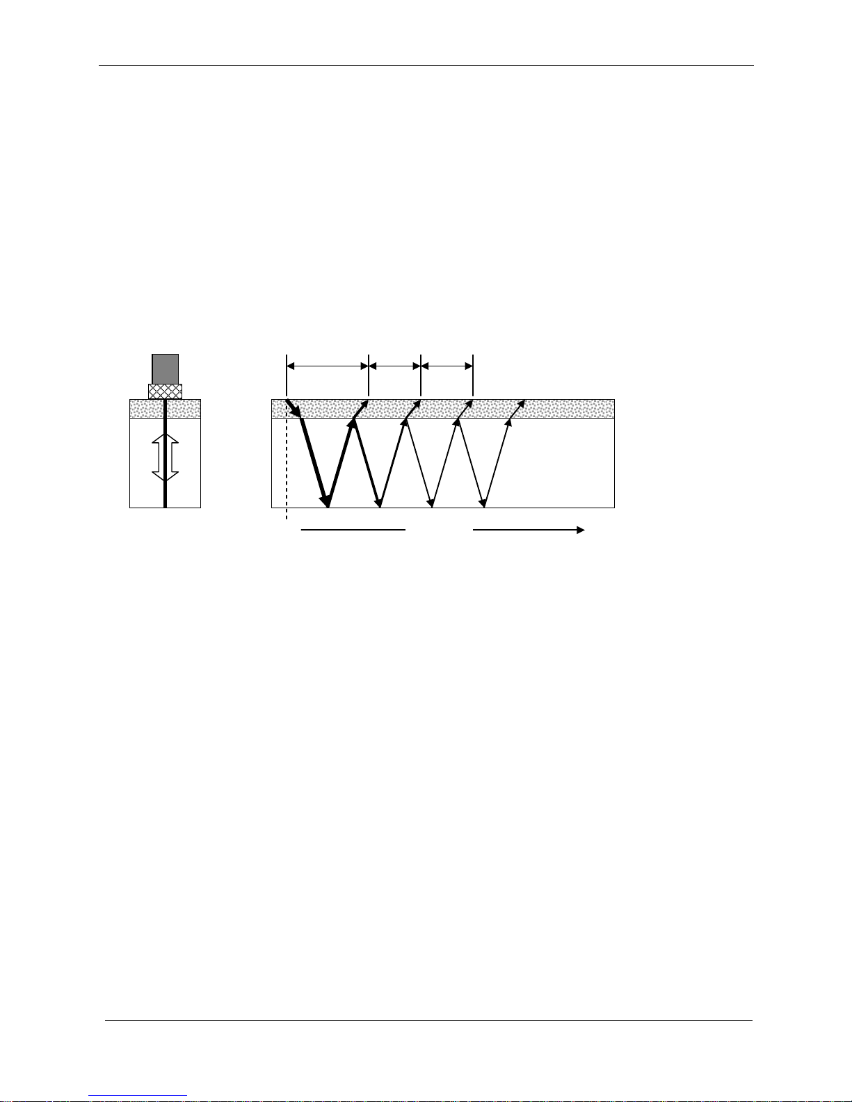
The Gauge works on the pulse-echo principle. The Probe transmits
a very short pulse of ultrasound which enters the test piece. The
Probe then acts as a receiver listening for return echoes,
converting them into electrical signals which are processed to
produce timing information that can be used to determine the
material thickness.
The mul
tiple-echo beam travel is depicted above, spread out in
time, to illustrate the timing method. In reality the beam path is
straight and perpendicul ar to the surface as the ultras oni c ene r gy
reverberates up and down within the metal (shown on the left).
Each time an echo is reflected back down, a small portion of the
energy comes up through the coatings and is detected by the
Probe which acts as a receiver (e1, e2 and e3).
The delay b
etween echoes at the Probe-face (t2 and t3) is exactly
equal to the time taken to pass through the metal twice, therefore
coatings such as paint are ignored and the measurement displayed
is the metal thickness only.
Triple Echo Verification
The Gauge requires 3 equi-spaced return echoes in order to
calculate a thickness measurement value (t2=t3). This method
ensures the Gauge only displays valid thickness values, the three
echoes provide a reliable method of signal verification. This
process is referred to as Triple Echo Verification.
e1
e2
e3
t2
t3
Valid Thickness Measurement only when : t2=t3
Time
Paint, Dirt etc.
Metal
0
t1
Probe
Page 9

M4-CYG3-M-ENG_Iss2.doc
Cygnus 3 Operating Manual
9
Cygnus Instruments
Cygnus Instruments Limited, founded in 1983, was the pioneer in
the development of the Digital Ultrasonic Multiple-Echo Technique
used for measurement through coatings. This has long been the
industry standard to ensure that accurate measurements are
taken without the need to zero the Gauge or remove any coatings.
Our philosop
hy is to work closely with our customers to provide
high quality products, engineered to serve heavy industry & harsh
environments. Cygnus Ult ras on ic thi ckness gauges are designed to
be reliable and simple to use. We have an unrivalled reputation in
over 45 countries around the world.
Page 10
Cygnus 3 Operating Manual
M4-CYG3-M-ENG_Iss2.doc
10
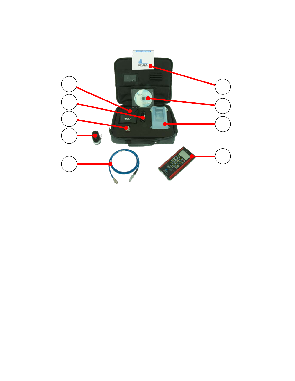
3 4 2 5 7 6 8 9 1
2. Gauge Kit Contents
1. Cygnus
3 Data Logger Gauge
2. Protective Silicone Sleeve
3. Cygnus 3 Operation Manual
4. Blue High-Flex Probe Cable, 1.5 m (4½ ft) *
5. Accessory Pouch, containing Couplant Gel, Spare Membranes,
Membrane Couplant, Membrane Locking Ring Key, 15 mm (or
1/2 inch) Test block and 3 x AA Procell Batteries
6. Adjustable Neck Strap *
7. Probe(s)
8. USB Cable
9. CD – Cygnus 3 Data Logger Manager
* The adju
stable neck strap and probe cable will be stored in
either the inside or outside pockets.
Page 11
M4-CYG3-M-ENG_Iss2.doc
Cygnus 3 Operating Manual
11
3. Gauge Preparation
The Gauge is supplied ready to use out of the box. Just insert the
batteries, connect the probe to the Gauge, turn on the power and
you are ready to take thickness measurements.
Fitting the Batteries
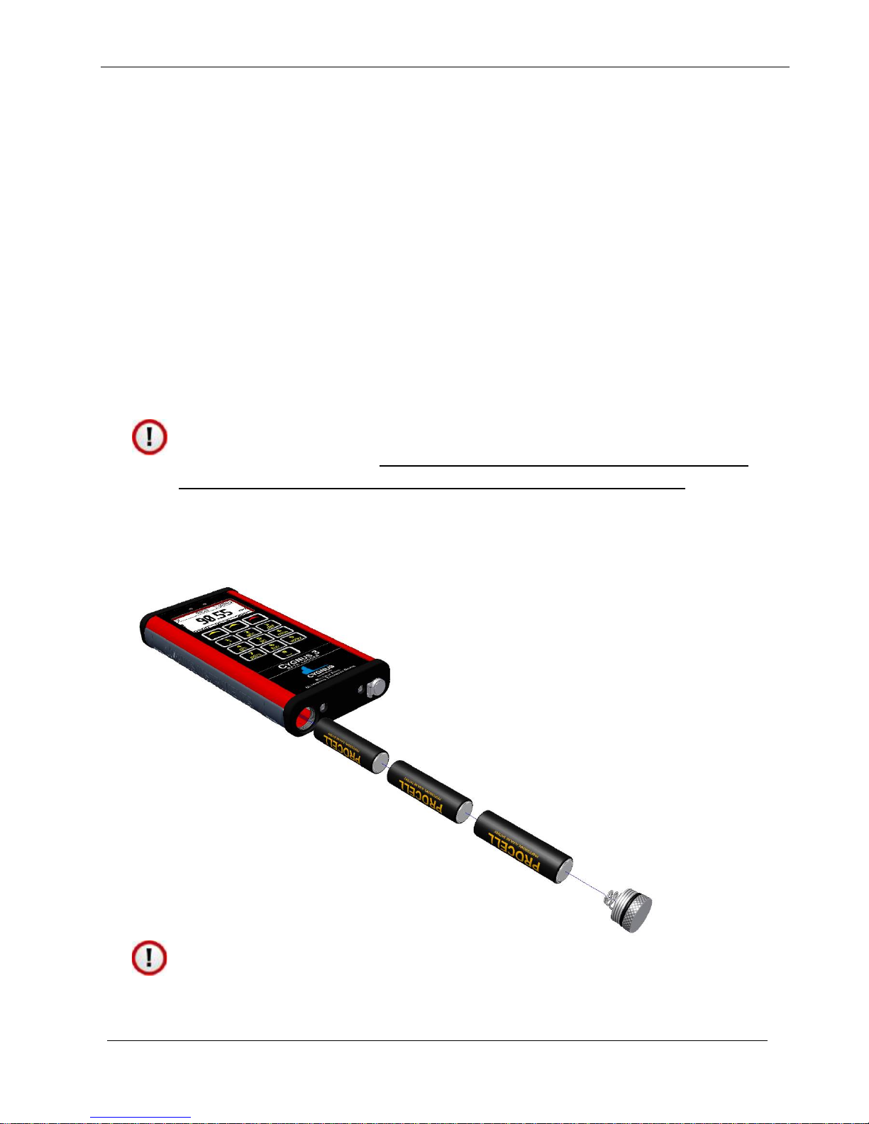
The Gauge requires 3 x AA/LR6/UM3 Batteries. Cygnus supplies
and recommends Duracell Procell Alkaline batteries.
The batteries are located behind a cover at the bottom of the
Gauge. Unscrew this cover to replace the batteries. The batteries
are inserted ‘+’ or ‘pip’ first.
When refitting the battery cover screw ensure it is done up
tightly by hand only. A drop of mem bra ne-oil on the threads
will help to ensure smooth operation and a good seal.
The Gauge is protected against damage from incorrect battery
insertion.
The Gauge can be fitted with NiCad or NiMH rechargeable
batteries but this may reduce the specified operating time.
+
3 x AA
Battery
Cover
Screw
Page 12
Cygnus 3 Operating Manual
M4-CYG3-M-ENG_Iss2.doc
12
Connecting the Probe
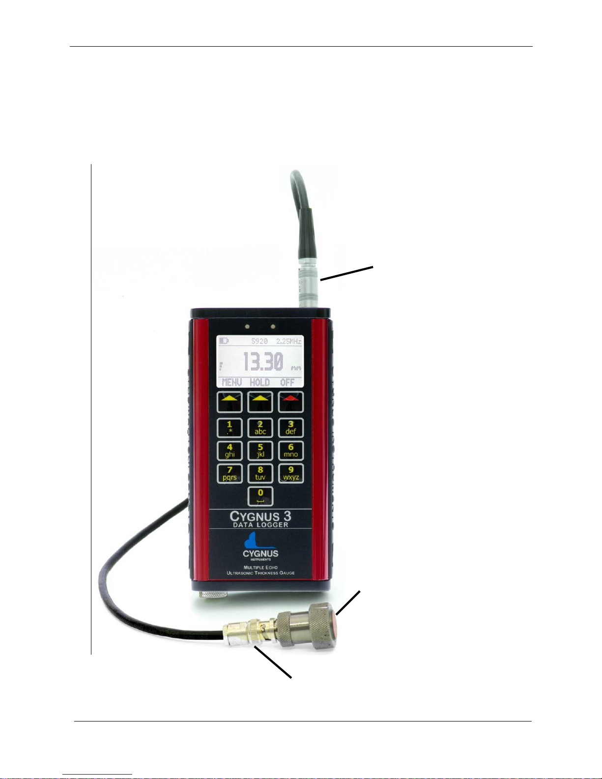
The Probe is connected to the Gauge with the supplied Probe Cable
as shown below. The Lemo 1 connector is removed by pulling back
on its body, not the cable.
Lemo 1
Probe
BNC Connector
Page 13
M4-CYG3-M-ENG_Iss2.doc
Cygnus 3 Operating Manual
13
Fitting the Protective Sleeve
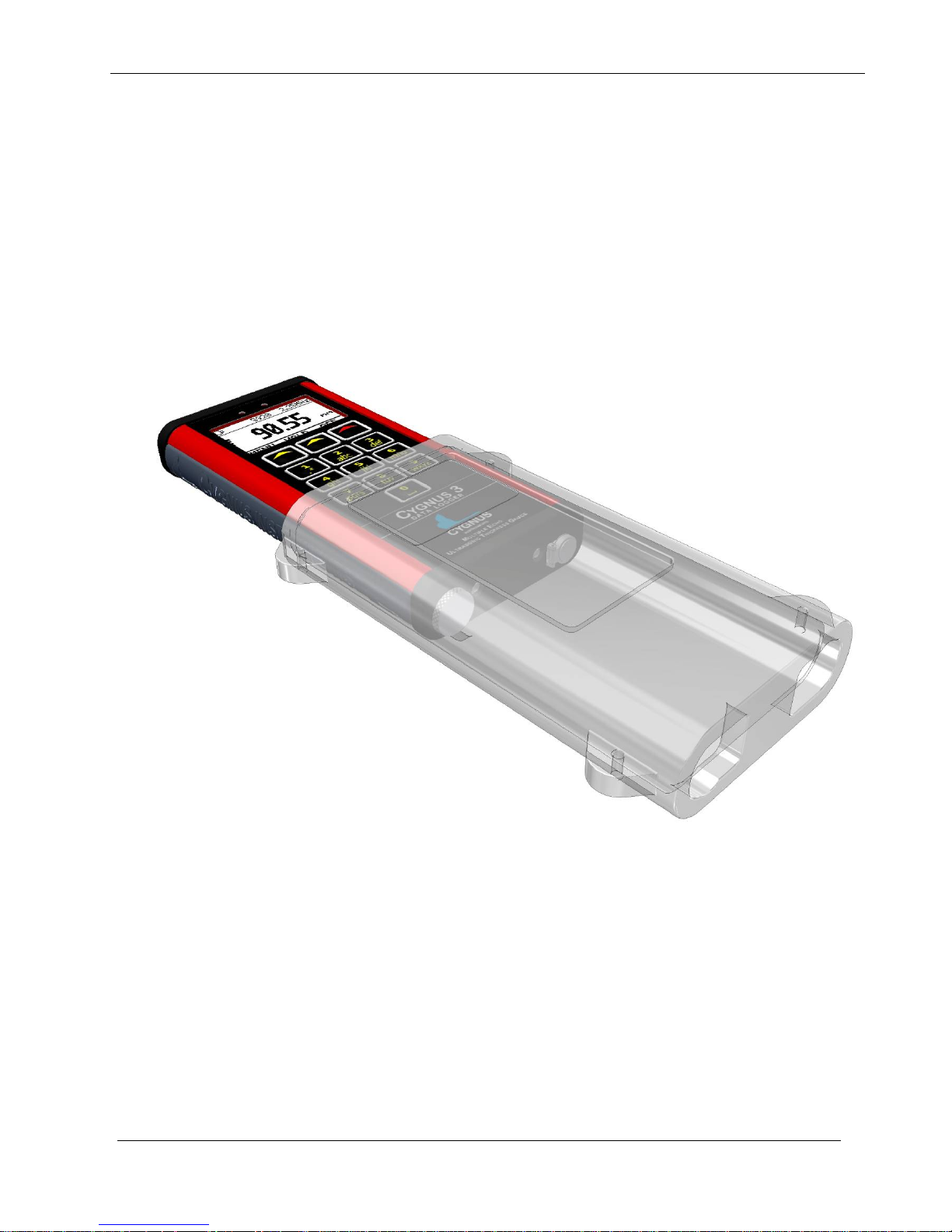
The Gauge is supplied with a protective Silicone Sleeve that fits
over the Gauge. This sleeve is designed to protect the Gauge
against bumps, scratches and dirt while in use whilst still allowing
Gauge operation and battery replacement.
To insert the Gauge simply push the Gauge down into the sleeve,
a lip at the top of the sleeve will retain the Gauge once fully
inserted.
The Gauge is removed by pushing it out from the bottom.
The sleeve also allows the Gauge to be worn on a belt or
suspended from the Neck Strap included in the kit.
Page 14
Cygnus 3 Operating Manual
M4-CYG3-M-ENG_Iss2.doc
14
Fitting the Neck Strap
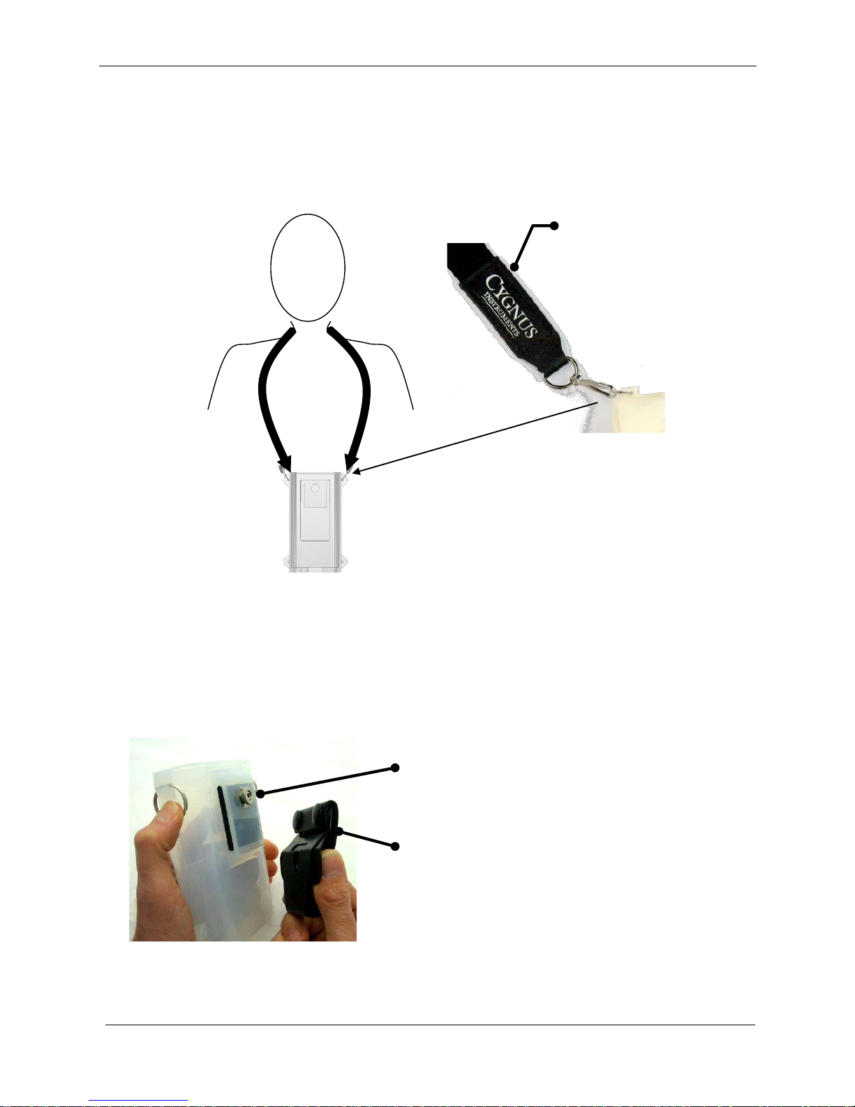
The Gauge is supplied with an adjustable Neck Strap. The ends of
the neck strap clip onto rings at the top of the protective silicone
sleeve.
Optional Krusell Belt Attachment
For attaching the silicone sleeve to a belt or harness we offer an
optional Krusell
®
belt clip. The belt clip is attached to the
protective silicone sleeve as shown below. This enables the Gauge
to be easily taken on and off the belt clip.
Krusell® Belt
Clip
Attachment
Point
Neck
Strap
Page 15
M4-CYG3-M-ENG_Iss2.doc
Cygnus 3 Operating Manual
15
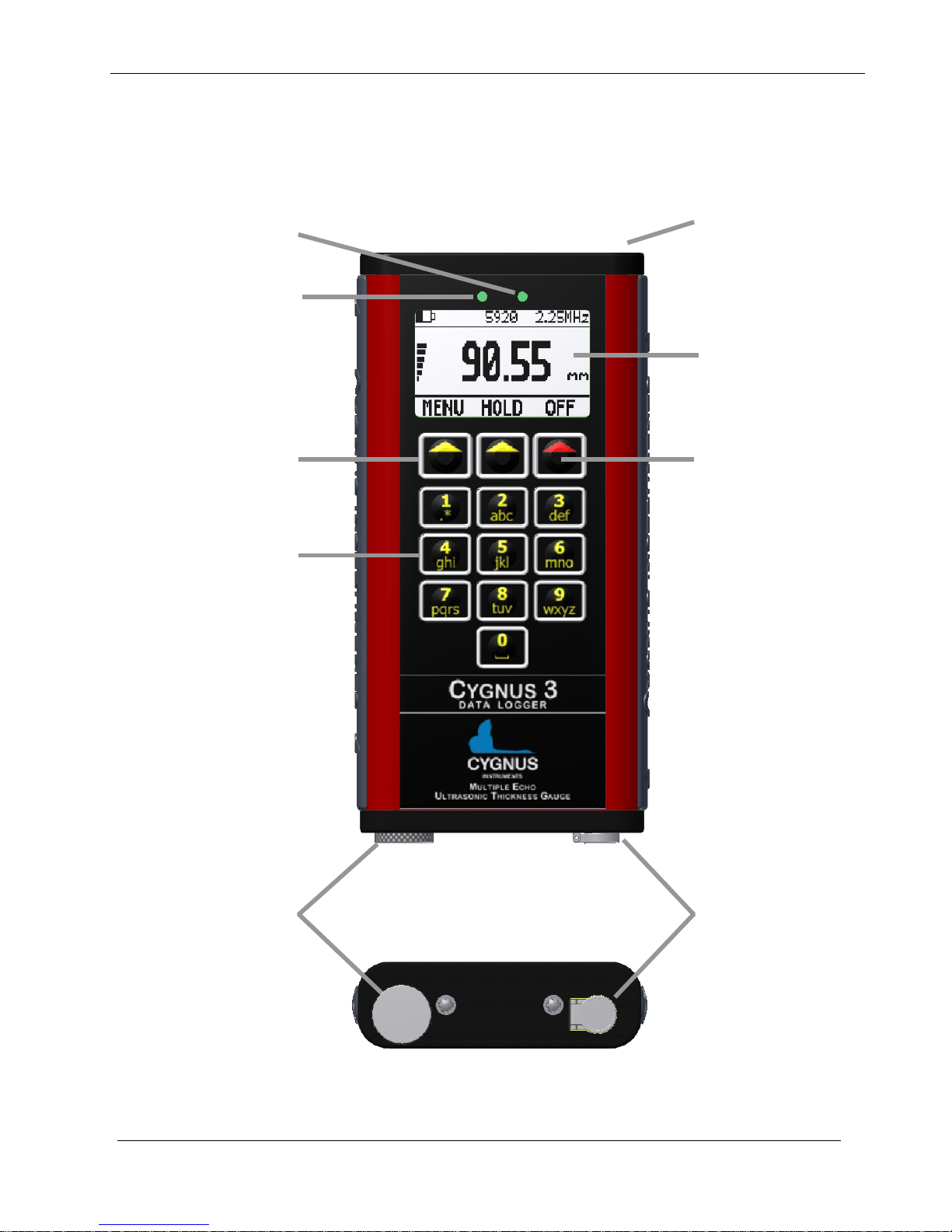
Battery
Cover
LCD
Display
Light Sensor
Power
ON/OFF
Key
Probe
Cable
Connection
3 Function
Keys
Signal LED
Alphanumeric
Keys
USB
Connection
4. Gauge Operation
Gauge Controls
Page 16
Cygnus 3 Operating Manual
M4-CYG3-M-ENG_Iss2.doc
16
Display and Automatic Backlight
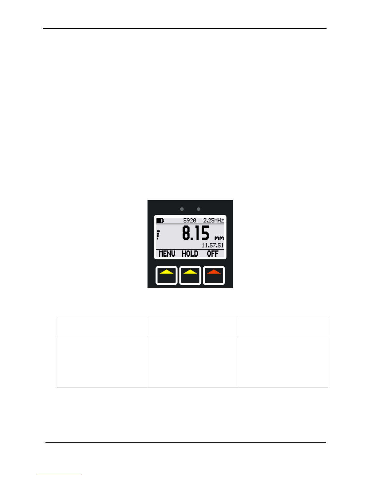
The Gauge uses a monochrome graphic LCD with 128 x 64 pixel
resolution. The LCD can be viewed in bright sunlight, and in low
light conditions a white-LED backlight is provided.
The LCD backlight is turned on automatically when the light level
drops below a pre-set level. The backlight will be also be turned off
after the gauge has been idle for 20 seconds (idle means no keys
pressed and no echoes detected).
Function Keys
The Gauge has three keys under the LCD screen with an upward
pointing triangle. The function of each key corresponds to the
word or symbol above it on the screen.
In the measuring screen the three keys are used for:
MENU HOLD* OFF
Pressing this key
displays the gauge
Menu.
Pressing this key
holds the displayed
thickness
measurement on the
screen.
Pressing this key
turns off the gauge
if the key is then
held for 1 second.
When in the menu and other screens the function of these three
keys change. The word or symbol displayed above the key on the
screen denotes the key’s function.
Page 17
M4-CYG3-M-ENG_Iss2.doc
Cygnus 3 Operating Manual
17
*When data-logging the middle key changes to the LOG function.
Numeric Keys
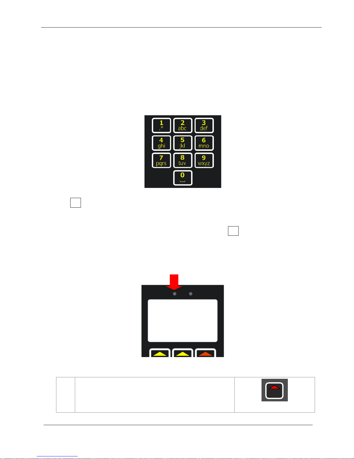
The Gauge has ten keys for alphanumeric data entry. Text and
numbers are entered by repeatedly pressing the key with the
required character, similar to entering text on a mobile phone
keypad.
The 1 key also provides these characters; + - . *
Example
To input the letter ‘S’ you would press the 7 key four times.
Signal LED
The Gauge has a red/green signal LED that illuminates when datalogging.
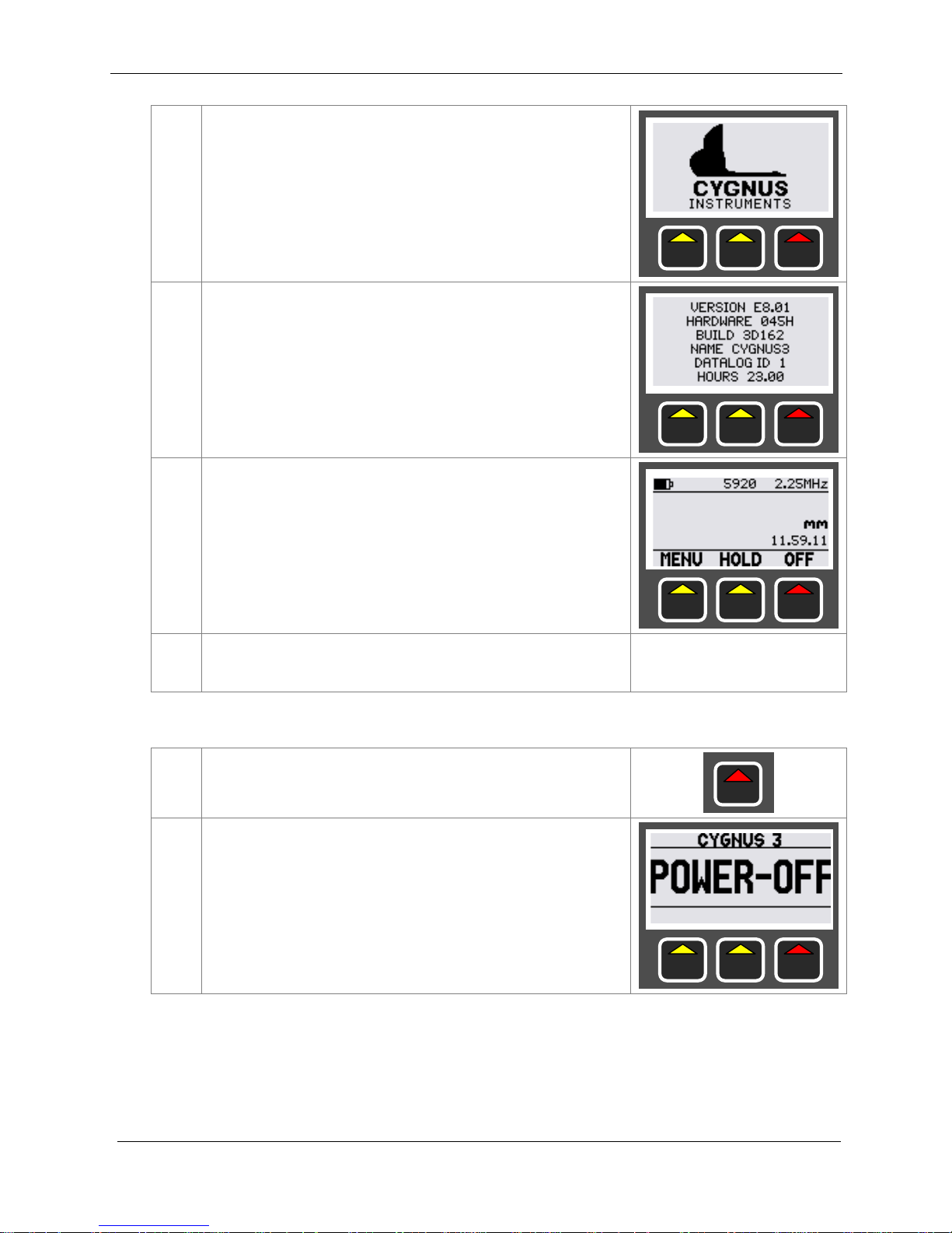
Turning the Gauge On
1.
Press the Power key (red Triangle key)
Page 18
Cygnus 3 Operating Manual
M4-CYG3-M-ENG_Iss2.doc
18
2.
The Cygnus Instruments logo is briefly
displayed
3.
The software and hardware version
information is briefly displayed
4.
The measurement screen is then
displayed
5.
The Gauge is ready to use
Turning the Gauge Off
1.
Press & Hold the Power button for 1
second
2.
The display shows ‘POWER OFF’ then
the Gauge turns off
Automatic Power Off
The Gauge will turn off automatically 5 minutes after the last
thickness measurement was taken.
Page 19
M4-CYG3-M-ENG_Iss2.doc
Cygnus 3 Operating Manual
19
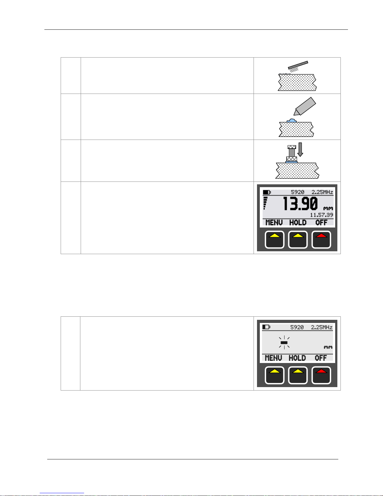
Taking a Thickness Measurement
1.
Remove all scale, rust, dirt or loose
coatings and brush the test area clean
2.
Apply couplant to the test surface
3.
Place the probe-face on the clean,
lubricated test surface and make firm
contact applying gentle pressure
4.
The Gauge will display a thickness
measurement or an indication of Echo
Strength if no valid measurement has
been found.
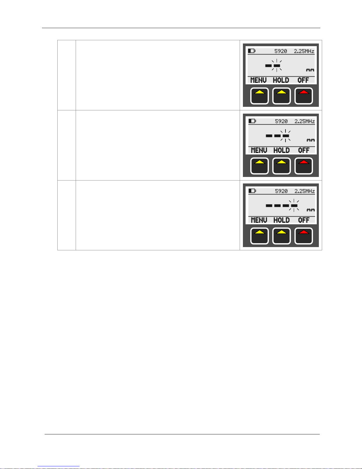
Echo-Strength Indicators
Should the Gauge be unable to detect a stable multiple-echo signal
it displays an Echo Strength indication to help the operator locate
a suitable position.
1.
1 Bar Flashing:
No echoes detected
Page 20
Cygnus 3 Operating Manual
M4-CYG3-M-ENG_Iss2.doc
20
2.
1 steady + 1 Bar Flashing:
Only 1 echo detected
3.
2 steady + 1 Bar Flashing:
Only 2 echoes detected
4.
3 steady + 1 Bar Flashing:
3 echoes detected but they are not
related
To help obtain a multiple echo reading the operator should
continue to move the probe around to locate a suitable reflector,
using a slight rocking motion.
Coupling Strength Indicator
When the Gauge displays a valid thickness measurement there is a
vertical coupling strength indicator displayed on the left side of the
screen. This shows the strength of the return echo signal giving
the user an idea of
a) How well the probe is coupled to the test material.
b) How attenuative the material and coating is.
Page 21
M4-CYG3-M-ENG_Iss2.doc
Cygnus 3 Operating Manual
21
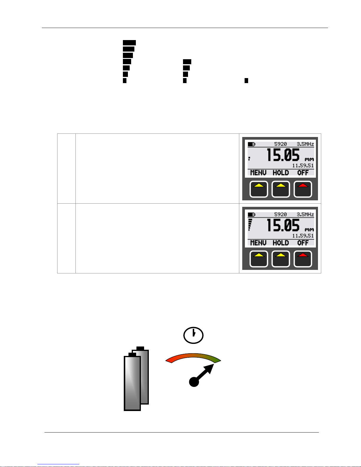
1.
This coupling strength indicator shows a
weak signal is being received.
2.
This coupling strength indicator shows a
strong signal is being received.
Battery Life
The Gauge will operate continuously for approximately 18 hrs
when fitted with Duracell Procell Alkaline 1500 mAh batteries.
Strong
Signal
Average
Signal
Weak
Signal
E
F
18 hrs
Page 22
Cygnus 3 Operating Manual
M4-CYG3-M-ENG_Iss2.doc
22
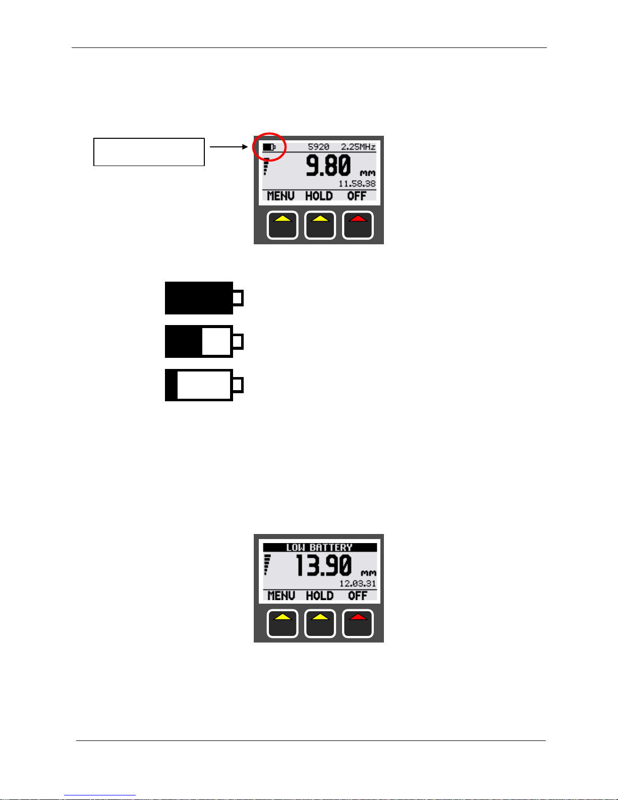
Battery Life Gauge
The battery level is displayed on the measuring screen at the top
left of the screen.
New Battery – Full.
Half Used battery.
Almost Flat battery.
Low Battery Warning
The Gauge will flash a Low Battery warning message at the top of
the screen when the battery level is below 15% capacity. This
means you have between 1 to 2 hours of gauge operation time
remaining.
Low Battery warning message.
Battery Level
Page 23
M4-CYG3-M-ENG_Iss2.doc
Cygnus 3 Operating Manual
23
5. Probes & Membranes
The Gauge should only be used with Soft-Faced probes
supplied by Cygnus Instruments.
Cygnus Soft-Faced probes are fitted with a Polyurethane
Membrane which provides better contact on rough surfaces and
protects the probe face from wear, prolonging the life of the
probe.
Check the membrane regularly as it is important the membrane is
changed as soon as it shows any signs of wear.
Probe Selection
Apart from the physical limitation of the probe size, the diameter
of the probe face (crystal) and the frequency affect the probe
performance, generally:
• Large diameter probes produce more energy which gives
better performance on heavily corroded materials.
• Higher Frequency probes produce a narrower focused beam
which is better when looking for small features or on thin
materials.
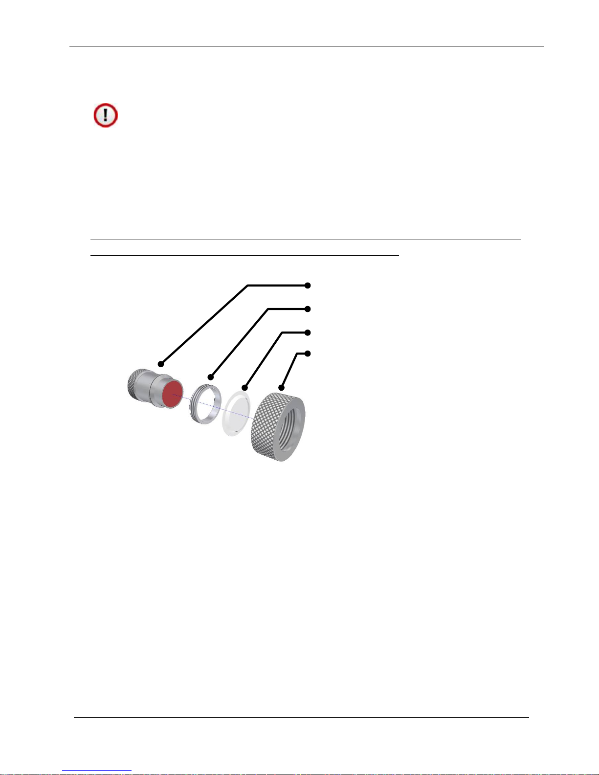
Probe Body
Locking Ring
Polyurethane Membrane
Knurled Ring
Page 24
Cygnus 3 Operating Manual
M4-CYG3-M-ENG_Iss2.doc
24
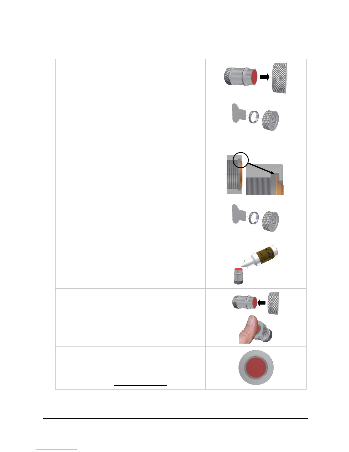
Changing the Membrane
1.
Unscrew the Knurled Ring from
the end of the Probe
2.
Use the Locking Ring Key to
unscrew the Locking Ring from
inside the Knurled Ring. The old
membrane can then be removed
and discarded.
3.
Place a new membrane into the
end of the Knurled Ring ensuring
it locates in the groove.
4.
Screw the Locking Ring back
inside the Knurled Ring and
tighten with the Locking Ring
Key.
5.
Place a few drops of Membrane
Couplant on to the probe face.
6.
Screw the Knurled Ring back
onto the probe. Use your thumb
to squeeze the couplant from
under the membrane as you
tighten the Knurled Ring down
7.
The membrane should have a
very thin film of couplant
between itself and the probe
face with no air bubbles.
Page 25
M4-CYG3-M-ENG_Iss2.doc
Cygnus 3 Operating Manual
25
Membrane Temperatures
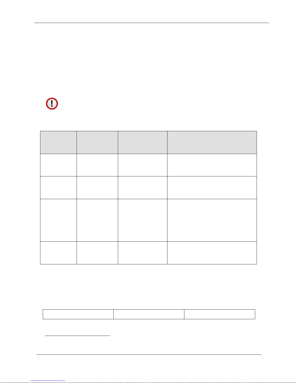
The standard polyurethane membranes are suitable for measuring
surfaces with temperatures up to 75°C.
For measuring on higher surface temperatures Teflon membranes
are available, they are suitable for temperatures up to 150°C. See
accessories on page 121.
When measuring hot surfaces reduce the probe contact time
to a minimum to avoid damaging the probe face and crystal.
Probe Selection & Specifications
Crystal
Diameter
Frequency
Measurement
Range
Application
13 mm
½ inch
2¼ MHz
3.0 – 250 mm1
0.12 – 10 inch
This is the standard probe
– suitable for most
applications.
13 mm
½ inch
3½ MHz
2.0 – 150 mm
0.08 – 6 inch
Suitable for measurement on
thinner sections where
surfaces are relatively rough
6 mm
¼ inch
5 MHz
1.0 – 50 mm
0.04 – 2 inch
The higher frequency and
narrower beam makes this
Probe ideal for measuring
small-bore tubing, thin section
plate and other areas where
access is limited.
13 mm
½ inch
5 MHz
1.0 – 50 mm
0.04 – 2 inch
Ideal for thin sections without
heavy corrosion.
Lower frequency probes offer better penetration on heavy
corrosion/coatings.
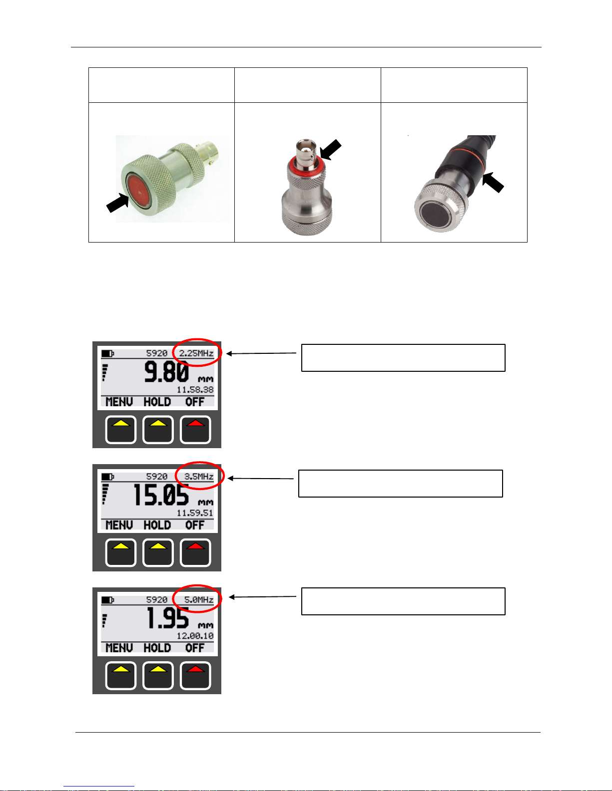
Probe Frequency Identification
The frequency of Cygnus probes is indicated by colour;
Red = 2.25 MHz
Orange = 3.5 MHz
Black = 5.0 MHz
1
To measure thicknesses on tall thin cylinders or columns the height-width ratio should be no
less than 1.0:0.6 (Height:Width) otherwise side reflections prevent measurement.
Page 26
Cygnus 3 Operating Manual
M4-CYG3-M-ENG_Iss2.doc
26
Old Style
Probes
Inox Probes with
BNC Connectors
Inox Remote
Probes
Coloured Probe Face
Coloured Ring under
BNC connector
Coloured Band on
Probe Cap
Automatic Probe Frequency Setting
The Gauge will automatically detect the frequency of the probe
connected and set the Gauge accordingly. The probe frequency is
displayed in the top right corner of the screen.
2.25 MHz Probe Detected.
3.5 MHz Probe Detected.
5.0 MHz Probe Detected.
Page 27
M4-CYG3-M-ENG_Iss2.doc
Cygnus 3 Operating Manual
27
6. Gauge Setup
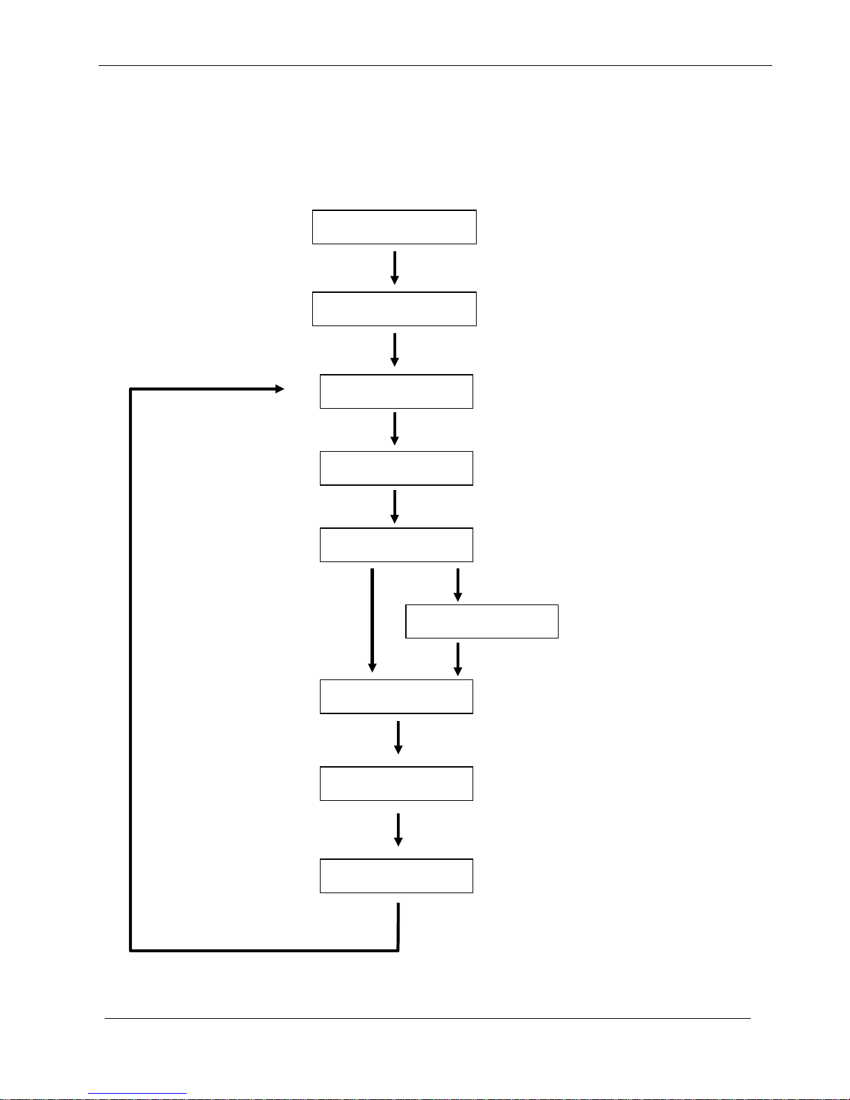
Gauge Menu Diagram
GAUGE MENU
UNITS
RESOLUTION
ALARM
MIN VALUE
BEEP
DEEPCOAT
Measurement Units:
mm or Inch
Measurement Resolution:
High 0.05mm (0.002 inch) or
Low 0.1mm (0.005 inch)
Minimum Thickness Alarm:
On or Off
Minimum Thickness Alarm:
Alarm Value
Valid Measurement Beep:
On or Off
Deep-Coat Function:
On or Off
Off
On
CLOCK
Set the Time and Date
MAIN MENU
Page 28
Cygnus 3 Operating Manual
M4-CYG3-M-ENG_Iss2.doc
28
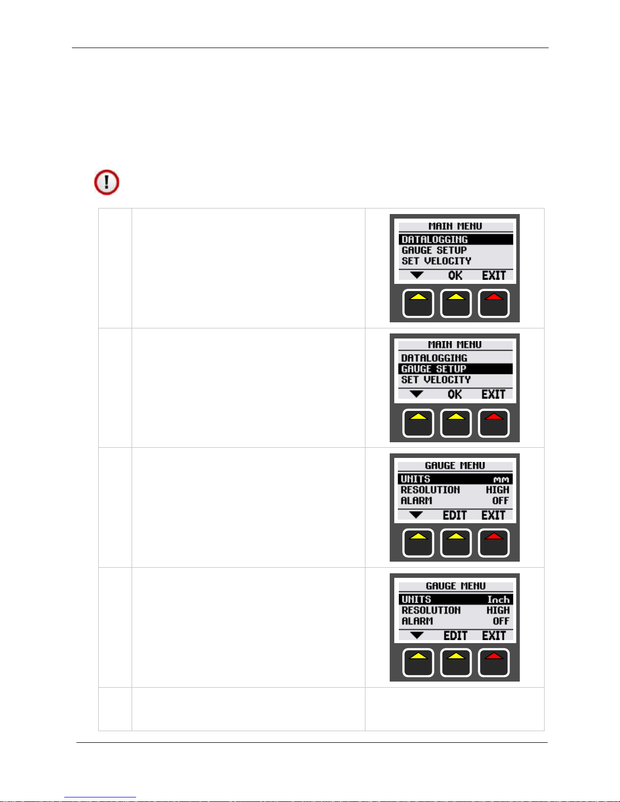
Measurement Units
The Gauge can display thickness measurements in either Metric
(mm) or Imperial (inch). Changing the measurement units does
not affect the calibration.
When data logging you can’t change the measurement units.
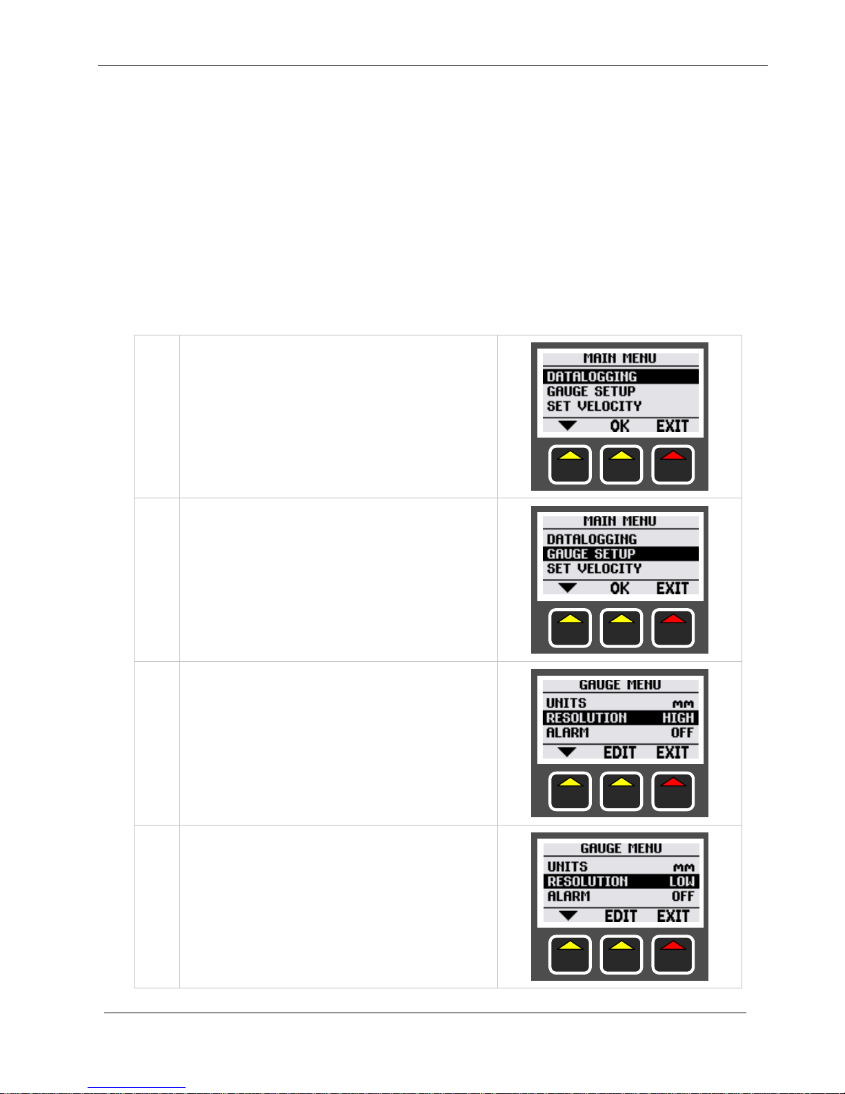
1.
Press the MENU key to display
the MAIN MENU
2.
Scroll down to GAUGE SETUP
then press OK
3.
UNITS should be highlighted
4.
Press the EDIT key to change
the UNITS setting:
mm to inch
inch to mm
5.
The gauge will automatically go
back to the measuring screen.
Page 29
M4-CYG3-M-ENG_Iss2.doc
Cygnus 3 Operating Manual
29
Resolution Setting
The Gauge can display the thickness measurements in two
resolutions:
• High Resolution : 0.05 mm / 0.002 inch
• Low Resolution : 0.1 mm / 0.005 inch
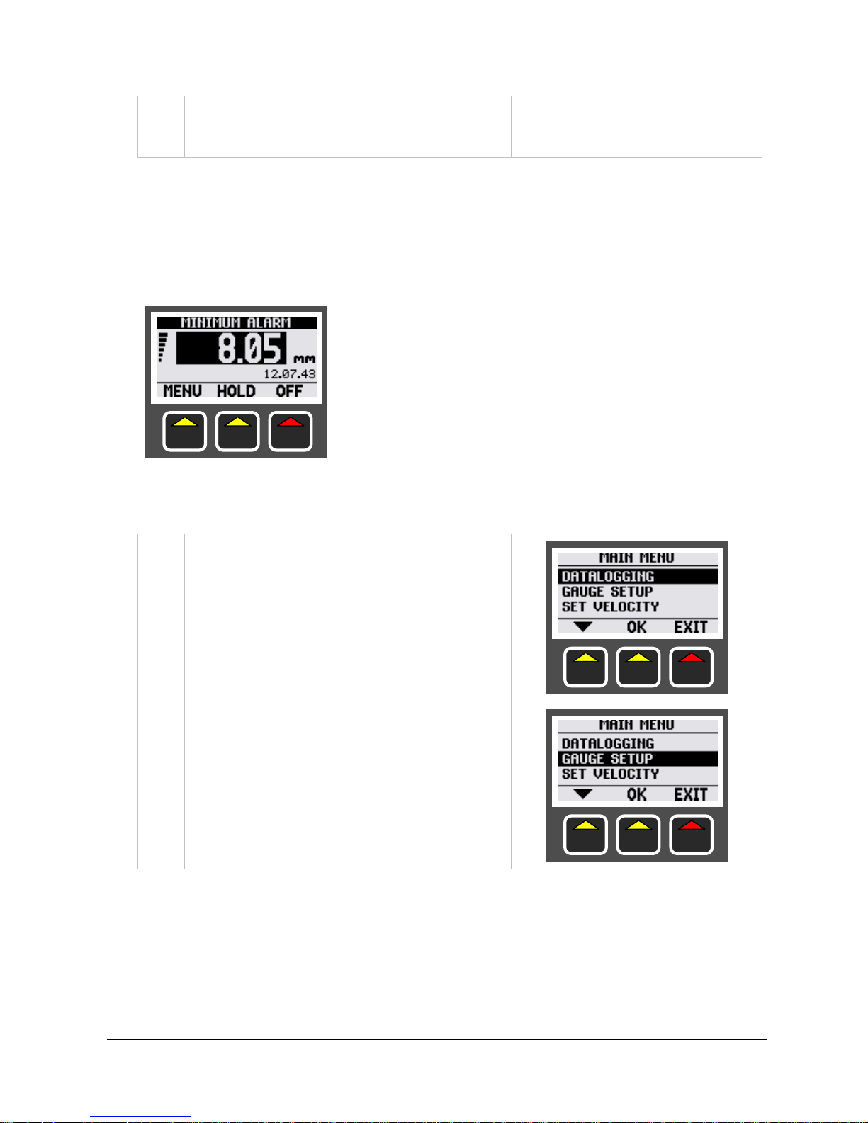
To change the Resolution setting:
1.
Press the MENU key to display
the MAIN MENU
2.
Scroll down to GAUGE SETUP
then press OK
3.
Scroll down to RESOLUTION
4.
Press the EDIT key to change
the RESOLUTION setting:
High to Low
Low to High
Page 30
Cygnus 3 Operating Manual
M4-CYG3-M-ENG_Iss2.doc
30
5.
The gauge will automatically go
back to the measuring screen.
Minimum Thickness Alarm Function.
The Gauge has a Minimum Thickness Alarm function that can be
used to alert the operator when the measured thickness value is
less than the set minimum value.
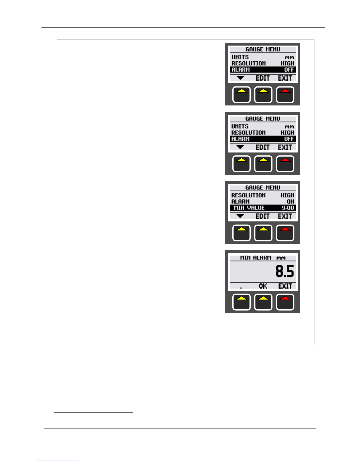
The Gauge will alert the operator with a
triple ‘beep’, light the RED Led, display the
thickness value in a black box and display a
MINIMUM ALARM message at the top of the
screen
To turn the Alarm function on or off:
1.
Press the MENU key to display
the MAIN MENU
2.
Scroll down to GAUGE SETUP
then press OK
Page 31
M4-CYG3-M-ENG_Iss2.doc
Cygnus 3 Operating Manual
31
3.
Scroll down to ALARM
4.
Press the EDIT key to change
the ALARM setting from On to
Off:
When the ALARM is ON the
MIN VALUE setting is shown.
5.
To change the MIN ALARM value
scroll down to MIN VALUE
Then press the EDIT key to
change the MIN ALARM setting.
6.
Use the number keys to enter in
the minimum thickness value as
required.
Press the OK key to save the
new MIN ALARM value.
7.
The gauge will automatically go
back to the measuring screen.
Deep Coat Function
The Gauge can normally measure metal thickness through
protective coatings up to 6 mm thick
2
, however using the DeepCoat function the Gauge can measure through coatings up to 20
mm thick
2
.
2
Depending on the properties of the coating and its velocity of sound.
Page 32
Cygnus 3 Operating Manual
M4-CYG3-M-ENG_Iss2.doc
32
Only operate the Gauge with Deep-Coat turned On when
measuring through protective coatings thicker than 6 mm.
Make sure Deep-Coat is turned Off when measuring metal with
coatings less than 6mm.
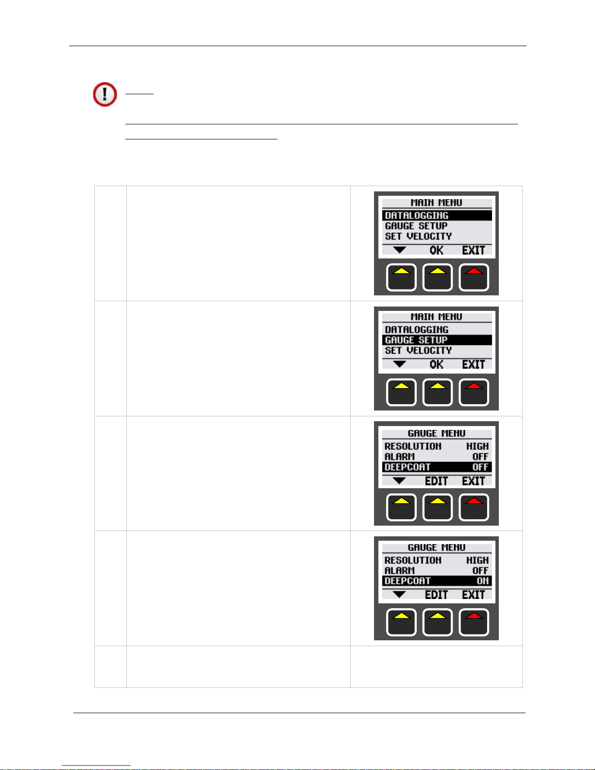
To turn the Deep-Coat function on or off:
1.
Press the MENU key to display
the MAIN MENU
2.
Scroll down to GAUGE SETUP
then press OK
3.
Scroll down to DEEPCOAT
4.
Press the EDIT key to change
the DEEPCOAT setting:
5.
The gauge will automatically go
back to the measuring screen.
Page 33
M4-CYG3-M-ENG_Iss2.doc
Cygnus 3 Operating Manual
33
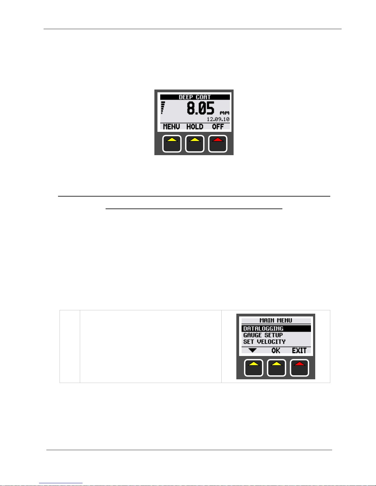
Deep Coat Warning Message
When the Deep Coat function is turned on a warning message is
flashed at the top of the display.
Deep Coat warning message.
Deep Coat mode must not be used when measuring
through coatings less than 6 mm.
Valid Thickness ‘Beep’ Function
The gauge can provide an audible ‘beep’ whenever a valid
thickness measurement is taken. This means the operator can
concentrate on probe positioning and listen for the ‘beep’ to signal
that a thickness measurement has been taken.
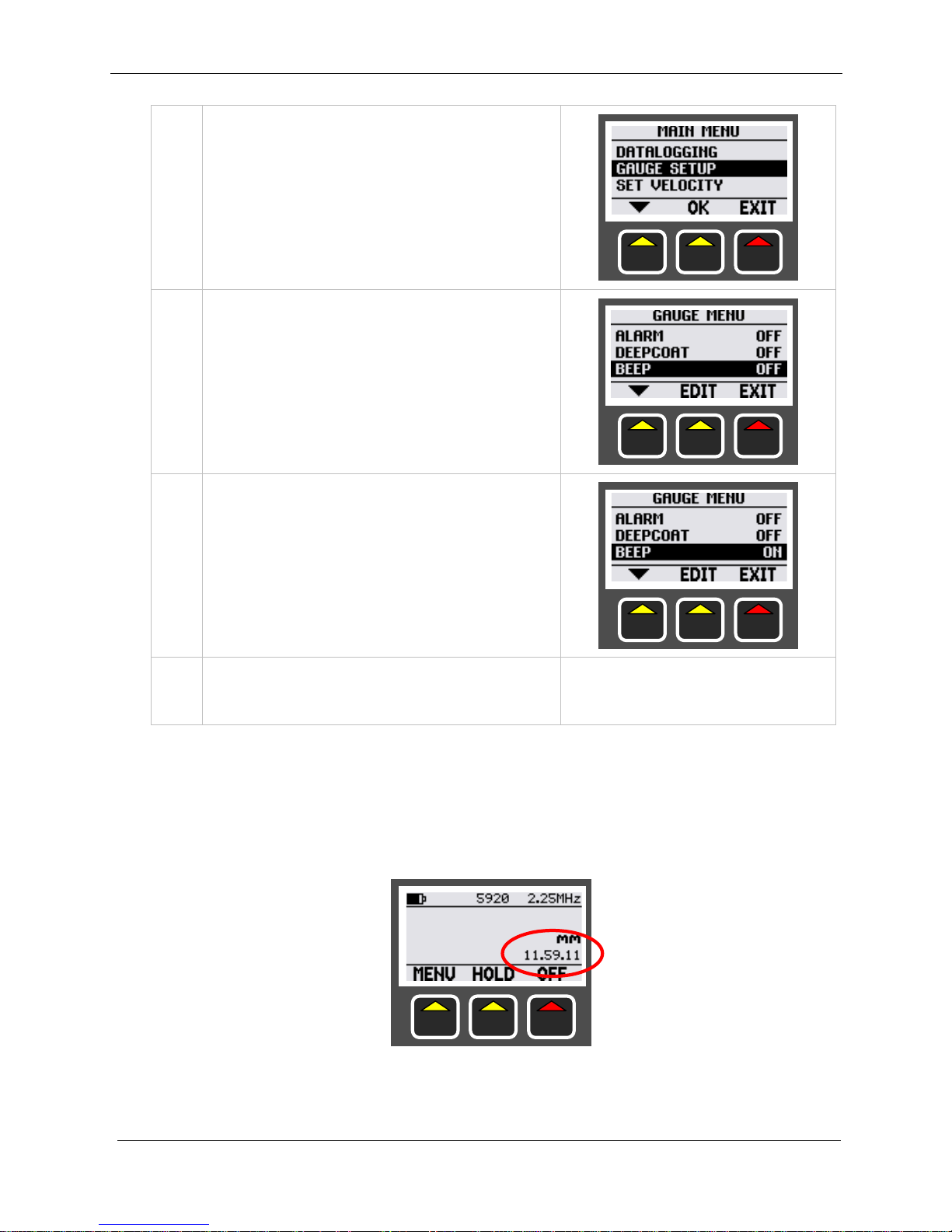
To turn the Beep function on or off:
1.
Press the MENU key to display
the MAIN MENU
Page 34
Cygnus 3 Operating Manual
M4-CYG3-M-ENG_Iss2.doc
34
2.
Scroll down to GAUGE SETUP
then press OK
3.
Scroll down to BEEP
4.
Press the EDIT key to change
the BEEP setting
5.
The gauge will automatically go
back to the measuring screen.
Setting the Time and Date
The Gauge has an internal clock to maintain the time and date for
the Data-logging functions. When not data logging the current
time is displayed on the measuring screen.
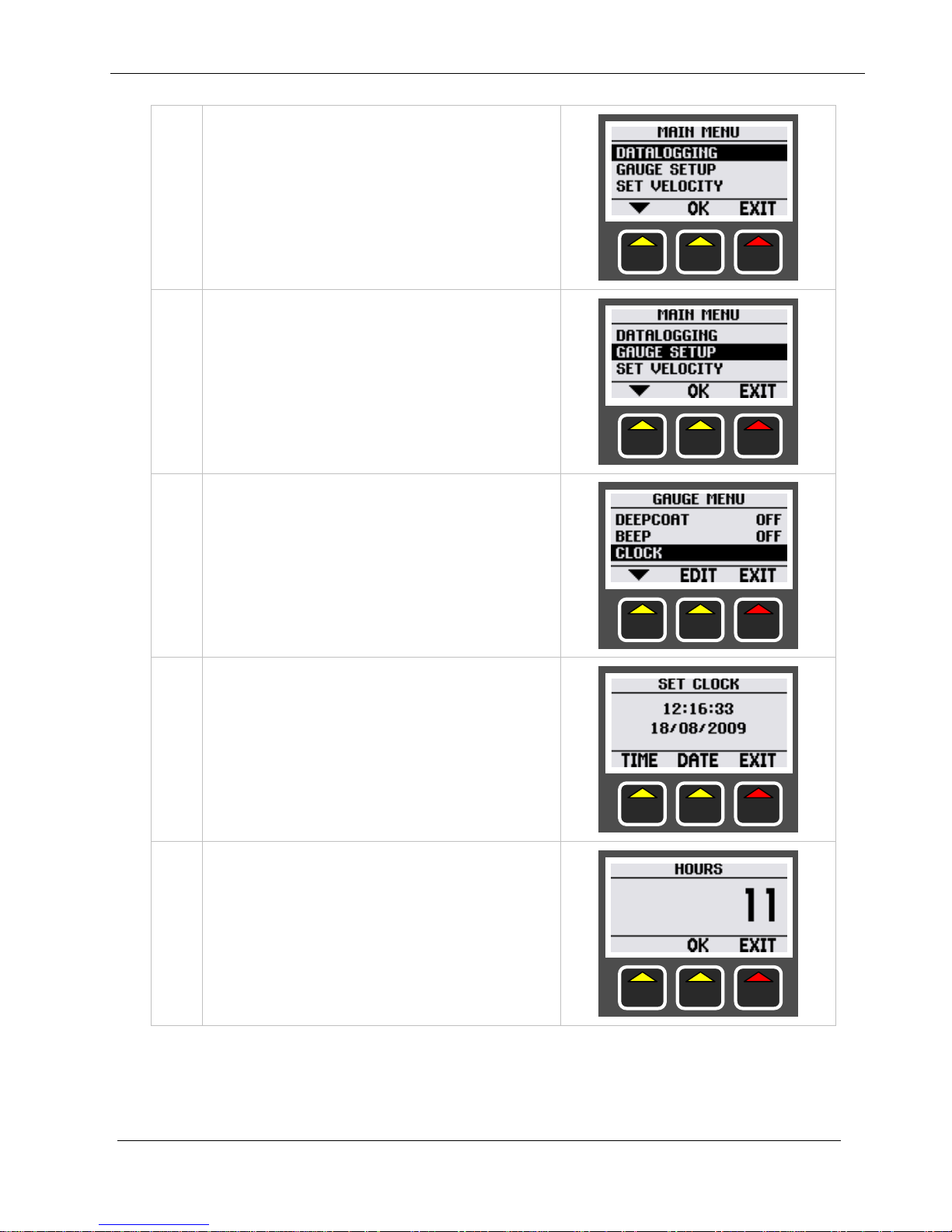
To set the time and date;
Page 35
M4-CYG3-M-ENG_Iss2.doc
Cygnus 3 Operating Manual
35
1.
Press the MENU key to display
the MAIN MENU
2.
Scroll down to GAUGE SETUP
then press OK
3.
Scroll down to CLOCK and press
EDIT
4.
The current time and date is
displayed
5.
Press TIME to set the time
Enter in Hours, Minutes &
Seconds followed by the OK key
each time.
Page 36
Cygnus 3 Operating Manual
M4-CYG3-M-ENG_Iss2.doc
36
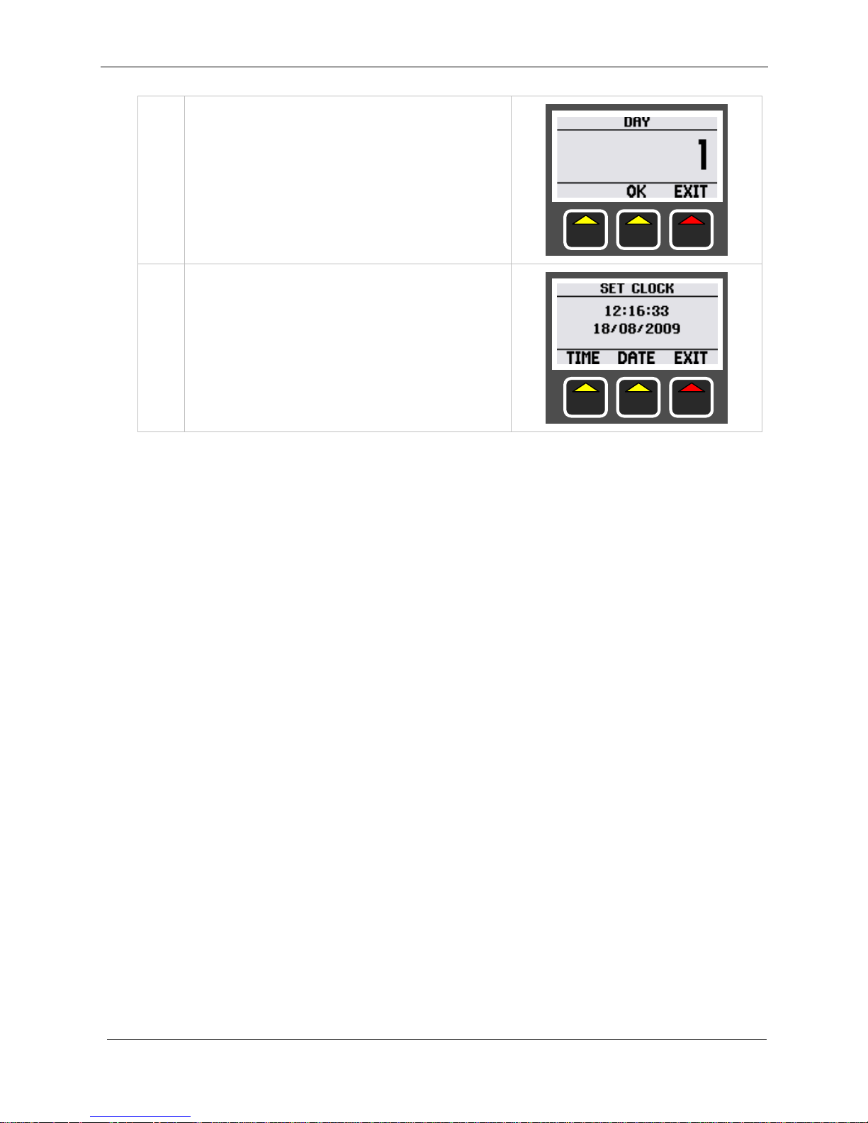
6.
Press DATE to set the date
Enter in Day, Month & Year
followed by the OK key each
time.
7.
When finished press EXIT to
return to the measuring screen
Page 37
M4-CYG3-M-ENG_Iss2.doc
Cygnus 3 Operating Manual
37
7. Calibration
Calibrating the Gauge
The Gauge is supplied tested and calibrated to BS EN 15317:2007.
The Gauge will have been calibrated to measure thickness
through steel (grade S355JO).
Either a 15 mm or 1/2 ” test block is supplied with the kit so the
Gauge can be quickly checked for correct operation. Note, this test
block is not intended to be used for calibration of the Gauge.
The best way to calibrate the Gauge is to
Calibrate using a
Known Thickness (see page 39) using a sample of the
material you intend to measure. This method determines the
velocity of sound for the material sample, which will always
be more accurate that using a ‘general’ velocity value. For
calibration instructions see page
38.
If there is no test sample available the Gauge can be calibrated by
Setting the Velocity of Sound directly (see page 40). A table
on
page 118 at the back of this manual lists common materials and
their velocity of sound value.
A third method is to leave the Gauge set to its factory-preset value
for Steel [5920 m/s or 0.2332 in/us], and then use a Conversion
Factor from the table of velocities on page 118
.
When data logging you can’t change the velocity or
calibration settings.
Page 38
Cygnus 3 Operating Manual
M4-CYG3-M-ENG_Iss2.doc
38
Calibration Menu
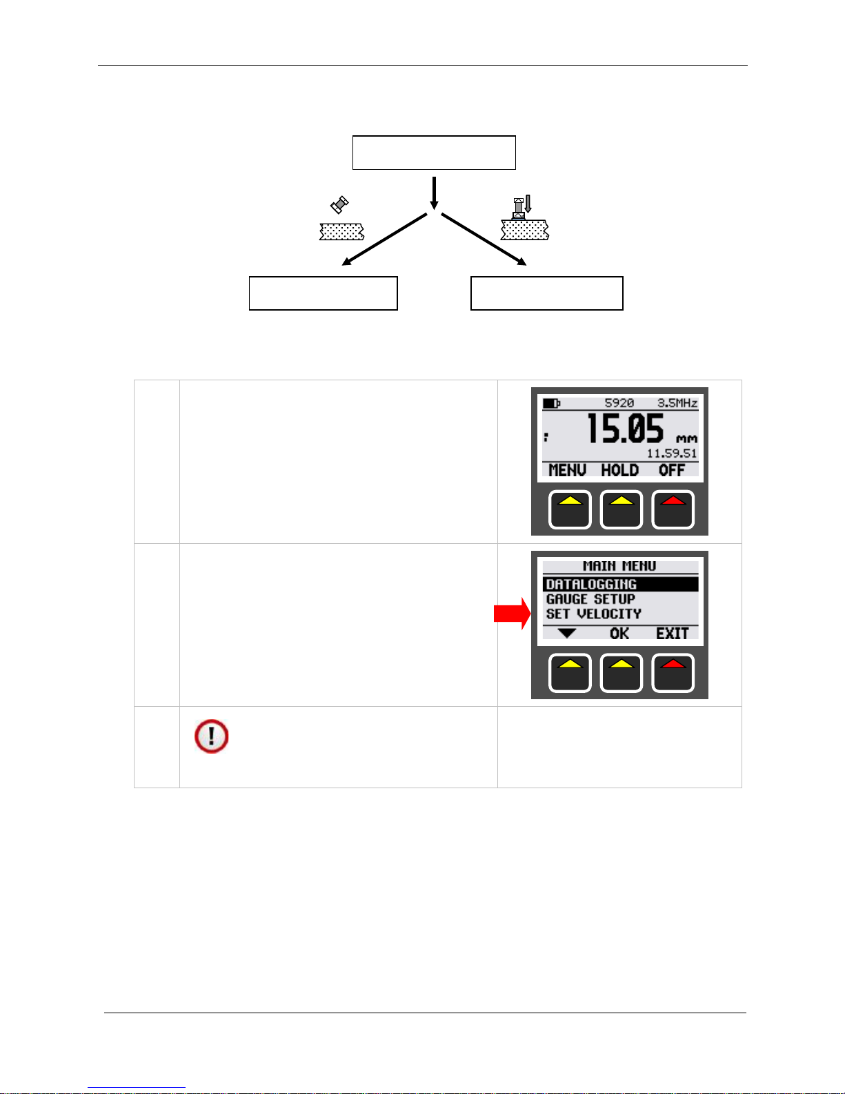
1.
To access the Calibration and
Velocity settings simply press
the MENU key
2.
Either CALIBRATE or SET
VELOCITY will be shown
3.
When data logging you
can’t change the velocity
or calibration settings.
VELOCITY
CALIBRATE
Calibrate to a
known thickness.
Set the Velocity
of Sound.
MAIN MENU
Page 39
M4-CYG3-M-ENG_Iss2.doc
Cygnus 3 Operating Manual
39
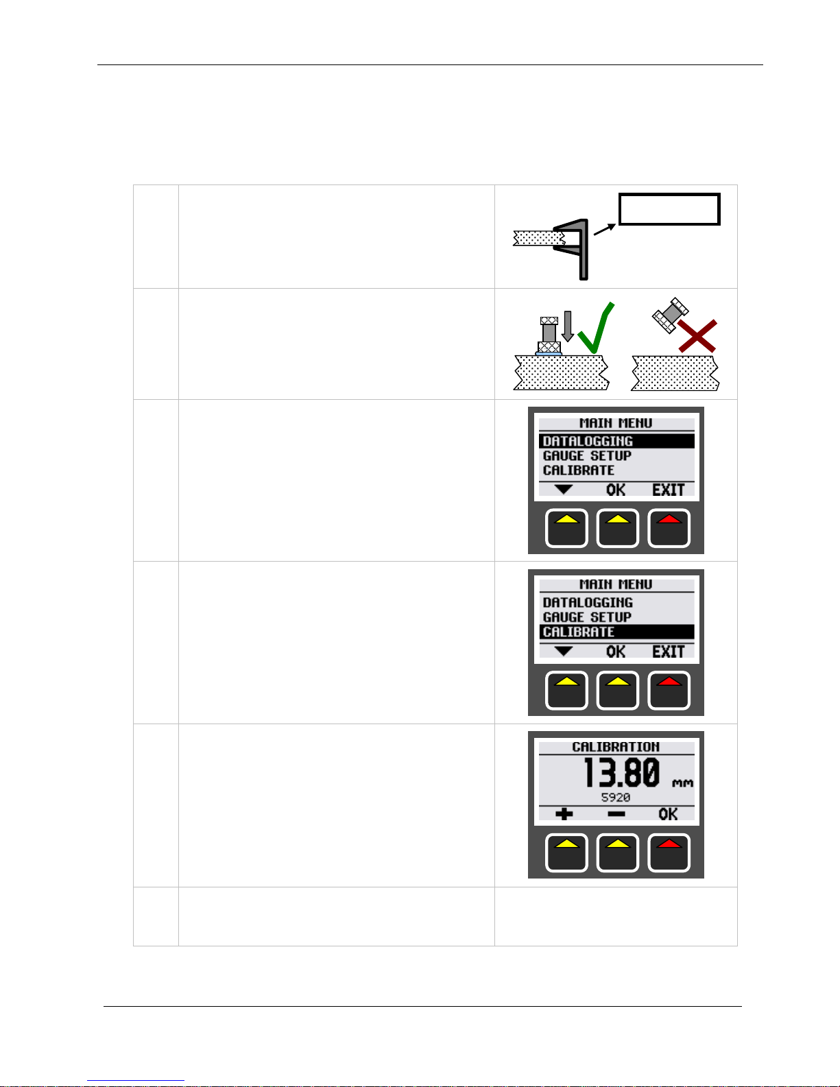
Calibrating to a Known Thickness (Single Point)
This method of calibrating the Gauge is the most accurate as the
Gauge calculates the velocity of sound for the sample material.
1.
Accurately measure the
thickness of your sample
material.
2.
Place the Probe on the sample
so the Gauge is displaying a
thickness value.
3.
Press the MENU key to display
the MAIN MENU
4.
Scroll down to CALIBRATE then
press the OK key
5.
Use the +
-
keys to change
the thickness value as required,
shown in large numbers.
The Velocity of Sound is shown
at the bottom of the screen.
6.
Press the OK key to save the
calibration values and exit.
13.80
mm
Page 40
Cygnus 3 Operating Manual
M4-CYG3-M-ENG_Iss2.doc
40
Setting the Velocity of Sound
The Gauge uses the Velocity of Sound value to calculate the
material thickness from the matched triple-echo time. A table on
page 118 of this manual lists velocity of sound values for common
material.
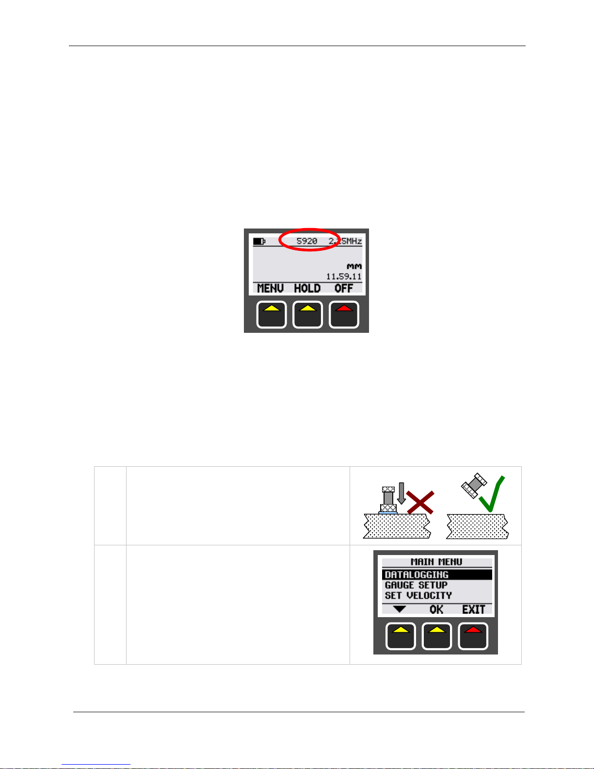
The current velocity of sound value is displayed in the centre at
the top of the measuring screen. In the screen below ‘5920’ means
a velocity of 5920 m/s as the gauge is in metric.
There are three options for setting the velocity of sound value;
1. Adjust the current value slightly using + and - keys
2. Type in a new velocity value using the number keys
3. Choose a velocity from a list of common materials
Displaying the Velocity Menu
1.
Ensure the probe is not t ou chi ng
anything so the Gauge is not
displaying a thickness value
2.
Press the MENU key to display
the MAIN MENU
Page 41
M4-CYG3-M-ENG_Iss2.doc
Cygnus 3 Operating Manual
41
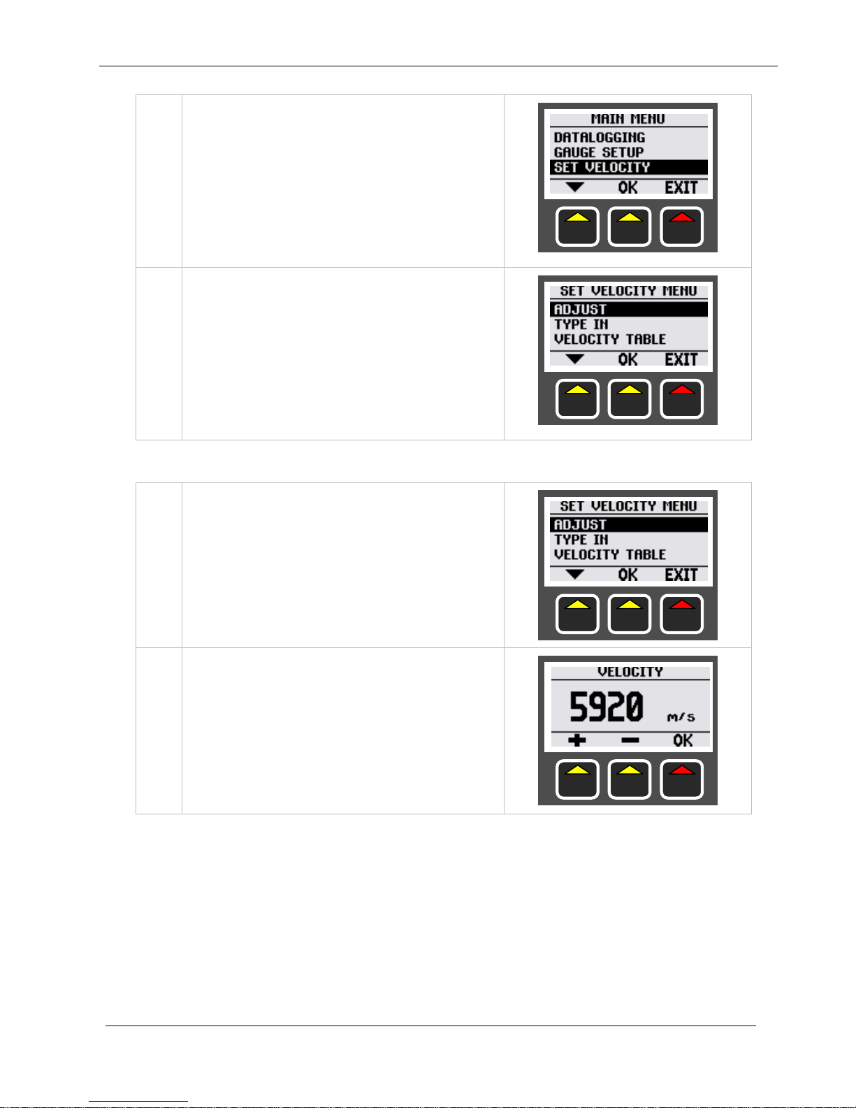
3.
Scroll down to SET VELOCITY
then press the OK key
5.
The SET VELOCITY MENU is
displayed. Use the arrow key to
select the desired option and
press the OK key
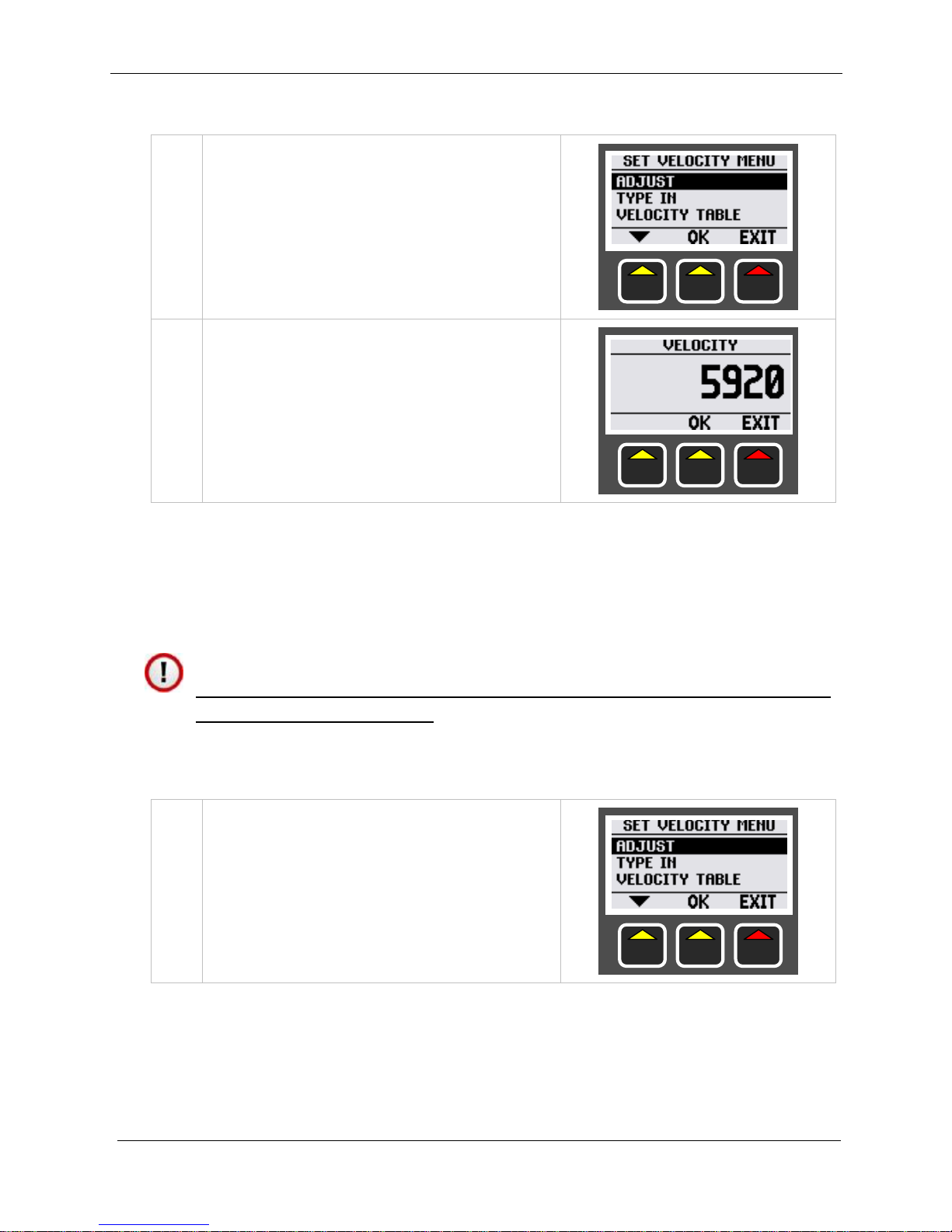
‘Adjust’ Velocity Menu Option
1.
From the VELOCITY MENU select
the ADJUST option and press the
OK key.
2.
The ADJUST option lets you
change the current velocity
value using
+ - keys.
Press the OK key to exit.
Page 42
Cygnus 3 Operating Manual
M4-CYG3-M-ENG_Iss2.doc
42
‘Type In’ Velocity Menu Option
1.
From the VELOCITY MENU select
the TYPE IN option and press the
OK key.
2.
You can now type in the required
velocity using the numeric keys,
followed by the OK key to exit.
‘Velocity Table’ Menu Option
The VELOCITY TABLE option displays a list of common materials
along with their velocity of sound values in either metric (m/s) or
imperial (in/us * 10000) depending on the gauge units setting.
The built in velocity table is intended to used as a guide only.
Wherever possible, the Gauge should always be calibrated on
the material under test. These velocities are given in good
faith and are believed to be accurate within the limits
described above. No liability is accepted for errors.
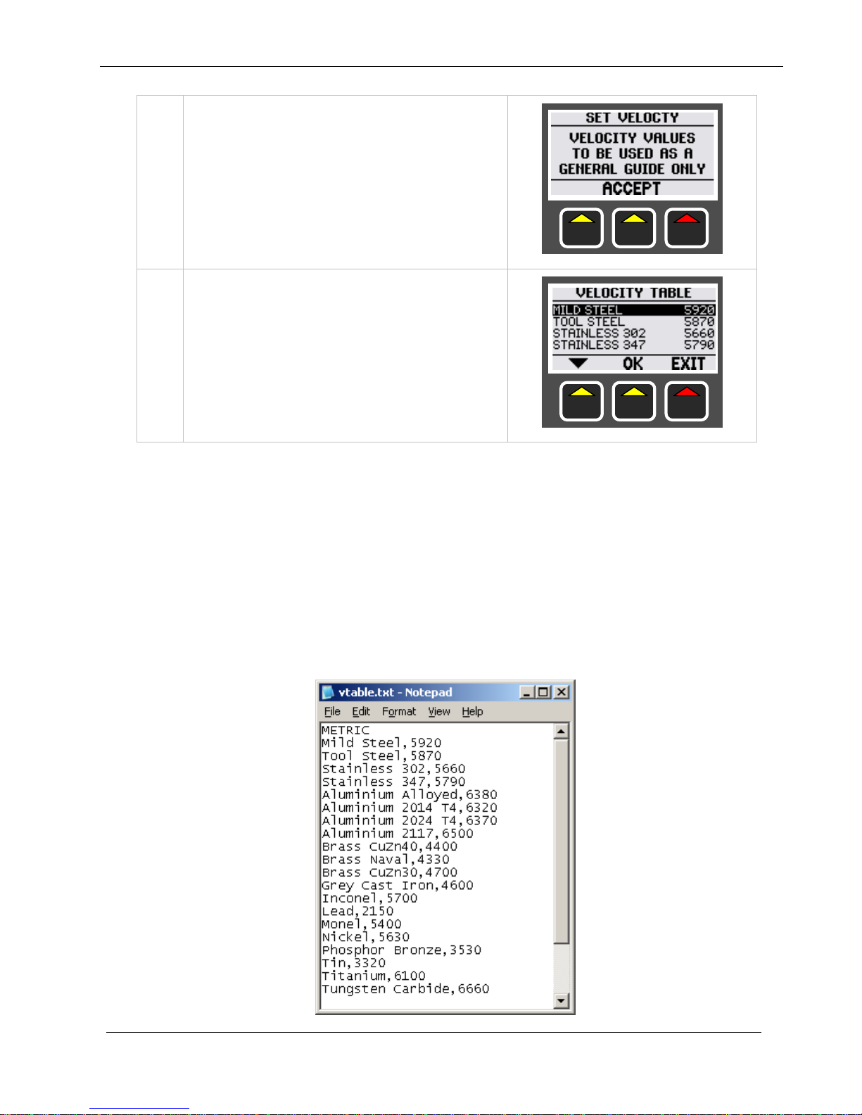
1.
From the VELOCITY MENU select
the VELOCITY TABLE option and
press the OK key.
Page 43
M4-CYG3-M-ENG_Iss2.doc
Cygnus 3 Operating Manual
43
2.
An information message is first
displayed to alert the user that
the velocity values should only
be used as a general guide.
You must press the ACCEPT key
to continue.
3.
Use the arrow key to select the
required material then press the
OK key to exit.
You will be asked to confirm
your selection.
Customising the Velocity Table
The velocity table gets its names and values from a file on the
internal memory card in the gauge. You can modify this file to add,
remove or edit the velocity table contents as required.
To view the velocity table file first connect the gauge to a
computer using the USB cable. Locate the file on the gauge called
‘vtable.txt’, you can open it with Notepad.
Page 44
Cygnus 3 Operating Manual
M4-CYG3-M-ENG_Iss2.doc
44
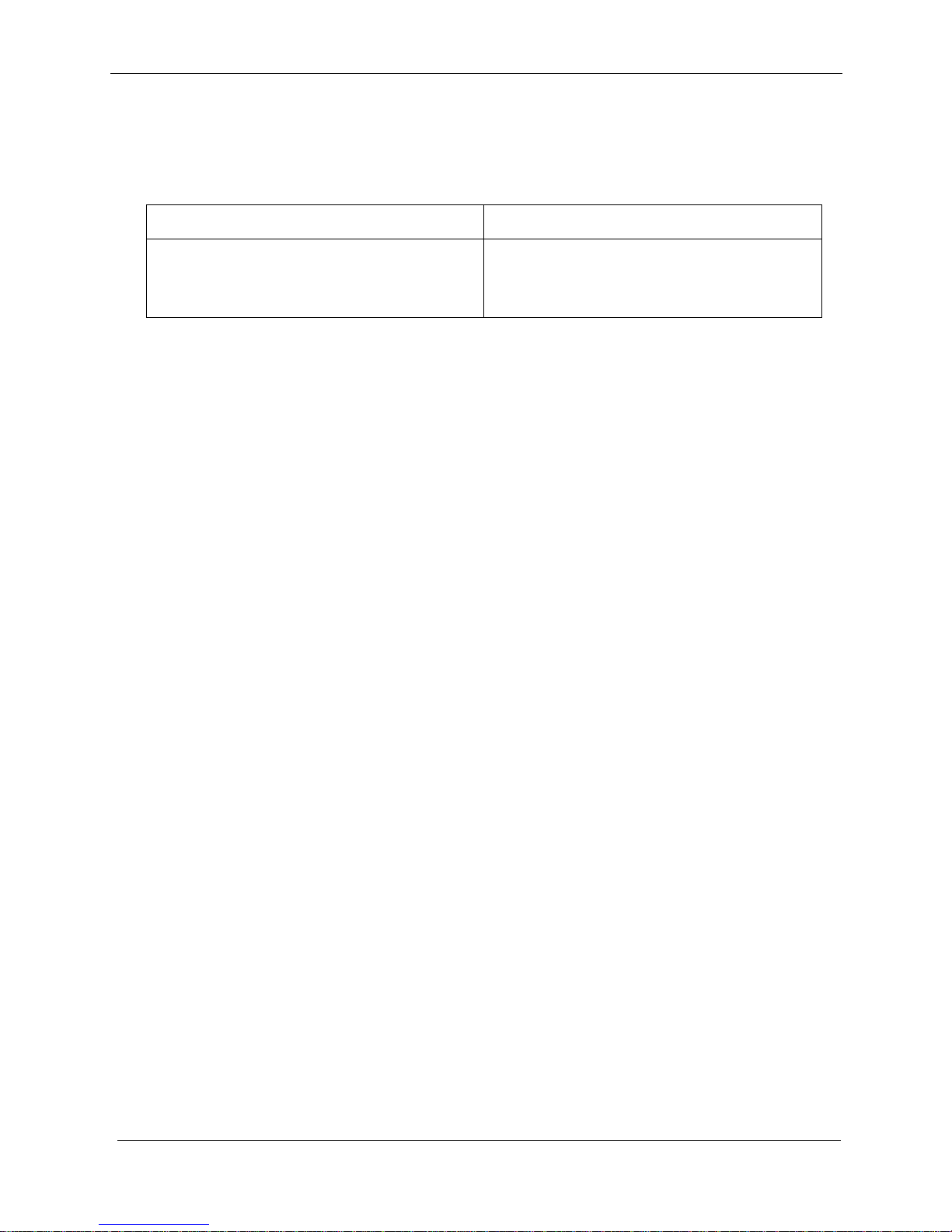
‘vtable.txt’ File in Notepad
The format of the file is;
for Metric Velocities
for Imperial Velocities
METRIC
name,velocity
Mild steel,5920
IMPERIAL
name,velocity
Mild Steel,0.2331
“name comma velocity new-line” – no spaces after the comma
There can be up to 20 velocity entries in the table.
Each name can be up to 20 characters in length.
Page 45
M4-CYG3-M-ENG_Iss2.doc
Cygnus 3 Operating Manual
45
8. Data Logging
The Cygnus 3 Gauge has the facility to store thickness
measurements on an internal mem ory c ard , this data may then be
transferred to a computer for producing thickness survey reports.
The Gauge has a USB port to allow data transfer between Gauge
and computer. When connected to a computer running Microsoft
Windows operating system the Gauge appears like a standard USB
memory stick allowing files to be easily transferred without
requiring driver installation. The memory is non-volatile and will
retain its contents during power off and battery removal.
There are three types of data logging Record Files which the
Gauge user can create:
QUICK LOG
This is a list of thickness measurements in
a linear format
GRID POINT
This is an X-Y grid of thickness
measurements.
You need to specify the number of rows
and columns.
TEMPLATE
This is a record file based on a template.
The template details how many thickness
points must be taken as well as their
name along with reference and minimum
thickness values.
A template may also contain up to 40 user
defined data fields, e.g. “Surveyor” or
“Date” or “Serial No”.
A company may issue a selection of
templates one for each type of survey in
use.
Page 46
Cygnus 3 Operating Manual
M4-CYG3-M-ENG_Iss2.doc
46
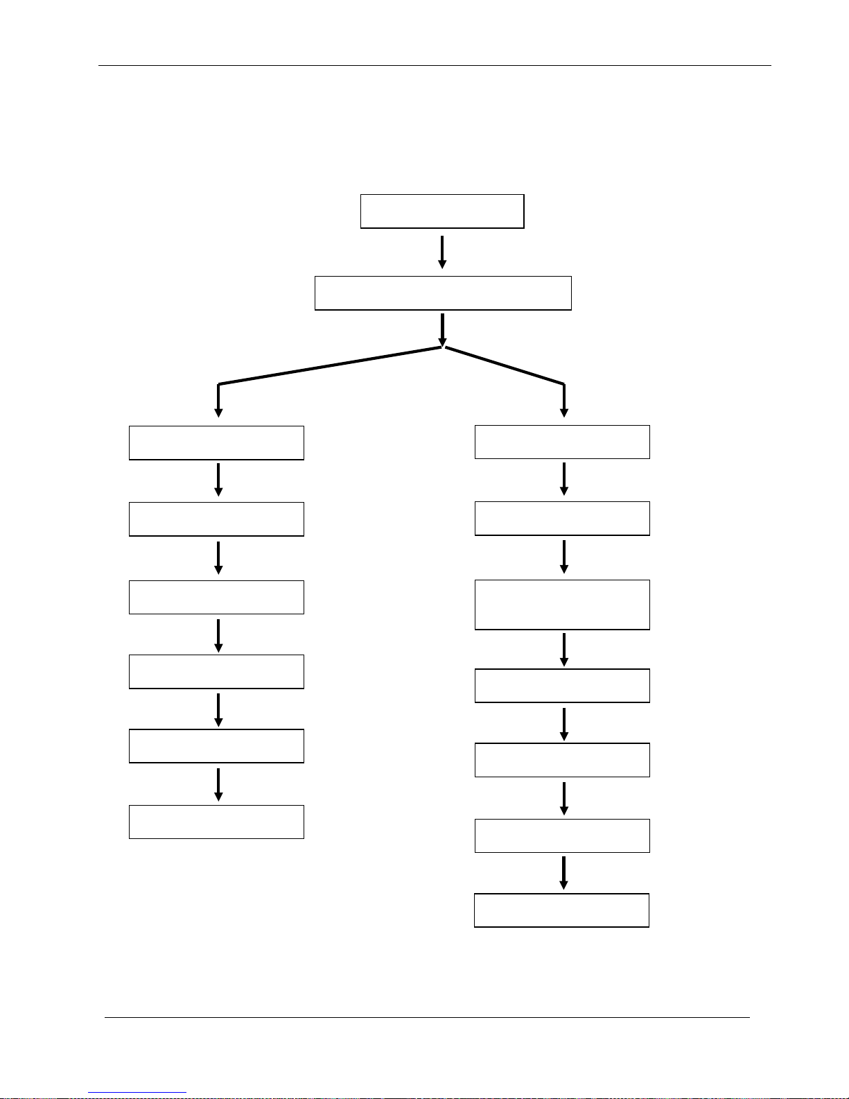
The Data Logging Process
The process of creating a new Record File, taking thickness
measurements, transferring to computer and finally creating a
report is straightforward, as illustrated below:
1. Create a new Record File on the Gauge
2. Start logging thickness measurements
3. Complete the thickness survey and close the Record File
4. Connect the Gauge to the computer
5. Transfer the Record File from Gauge to computer
6. Create paper or PDF reports on the computer
Windows software, “Cygnus 3 Data Logger Manager”, is supplied
to transfer Record Files and to create reports. It is also used to
create Template Files and to transfer these to the Gauge, see page
73.
An Excel spreadsheet Add-In is provided to automate the process
of inserting Record File data into spreadsheet reports, see page
92.
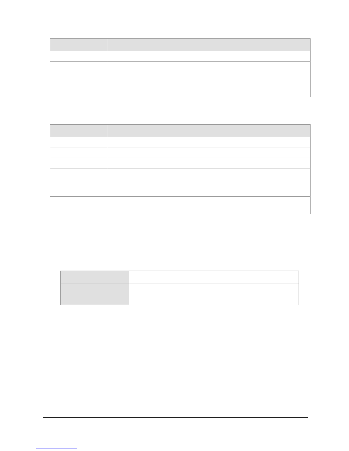
Contents of a Record File
Each Record File contains the following information:
Item
Description
Notes
Name
The name of the record file
Units
Either mm or inch units
Velocity
The velocity of sound used
Probe Type
The probe type used
2.25 / 3.5 / 5.0 MHz
Create Date
The time and date the record was
created.
Comment
Any user comments
Gauge ID
The gauge serial number
Template files contain the following additional information:
Page 47
M4-CYG3-M-ENG_Iss2.doc
Cygnus 3 Operating Manual
47
Item
Description
Notes
Template file
Name of spreadsheet template file
Worksheet
The worksheet on the template file
User Field 1
to
User Field 10
Additional User Fields for extra
information.
Each measurement point contains the following information:
Item
Description
Notes
Name
The name of the measurement point
Reference
The reference thickness
optional
Minimum
The minimum thickness
optional
Measurement
The measured thickness value
Time
The time the measurement was
made
Cell Location
The spreadsheet cell location for the
measurement value
optional
Record File Names
When you first create a new Record File it will need a file name like
any file on a computer. The gauge has two options for getting this
file name:
User Entered
The user must type in a file name
Auto File
Name
The gauge creates a unique numeric file
name for you
User Entered File Names
This assumes the user will choose a unique and appropriate file
name. The file name could represent the name or number of the
structure being surveyed.
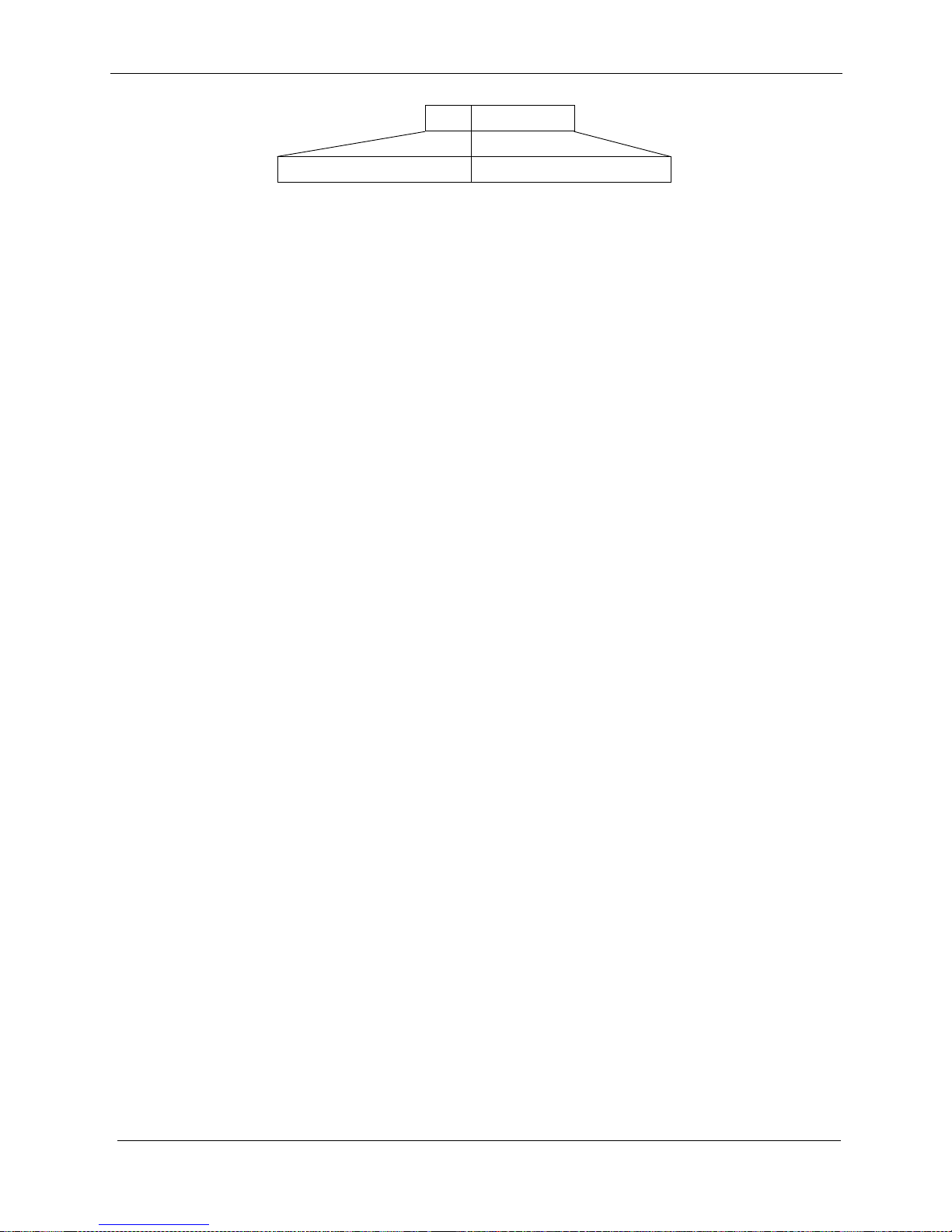
Auto File Name
The file name is a combination of the GaugeID number and a
sequential 6 digit number as follows:
Page 48
Cygnus 3 Operating Manual
M4-CYG3-M-ENG_Iss2.doc
48
01
000001
GaugeID
Sequential No.
The sequential number is increased by 1 each time a new Record
File is created. When it reaches 999999 it will roll-over back to
000000 - after 999999 record files have been created.
GaugeID Number
The GaugeID number is a number between 01 and 99 that can be
assigned to each gauge. When more that one gauge is used by a
company each gauge would be given a unique GaugeID number
(i.e. 1, 2, 3..) so Record Files from all the gauges can exist in the
same folder and be identified.
The GaugeID number can be changed in the Factory Menu screen.
Page 49
M4-CYG3-M-ENG_Iss2.doc
Cygnus 3 Operating Manual
49
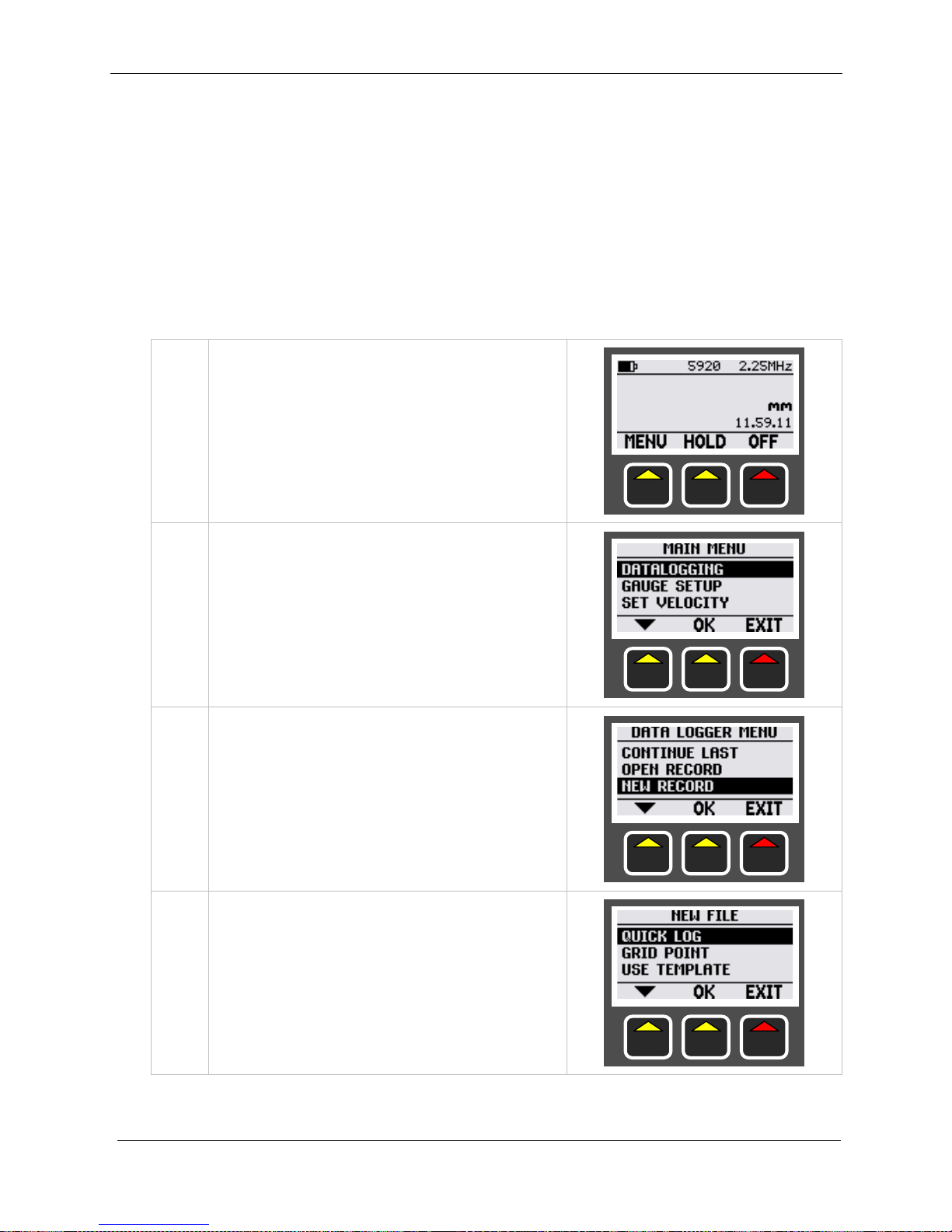
Data Logger Menu
The Data Logger Menu has two paths depending on whether the
Gauge is data logging or not.
DATA LOGGING MENU
CONTINUE LAST
OPEN RECORD
Continue the
last record file
if there is one
Open an
existing record
file
MAIN MENU
NEW RECORD
Start a new
record file
PROTECT RECORD
Protect a record
file
DELETE RECORD
DELETE ALL
RECORD DETAILS
MOVE POSITION
ADD RADIAL
POINTS
STOP LOGGING
ADD COMMENT
TEMPLATE FIELDS
Not Logging
Logging
Delete a record
file
Delete all
record files
Show record
file details
Move position in
the record file
Add additional
points
Stop logging
Add a text
comment to the
record file
View or edit
user fields in a
template record
file
AUTO LOG
Turn the AUTO-
LOG feature on
or off
Page 50
Cygnus 3 Operating Manual
M4-CYG3-M-ENG_Iss2.doc
50
Quick Log Record Files
Quick Log Records contain a linear list of thickness measurement
points. To create a Quick Log Record only the filename needs to be
entered in before measurements can be logged. When the
thickness survey is completed the Quick Log Record is closed by
stopping data logging. The maximum number of measurement
points that can be stored in each record file is 5000.
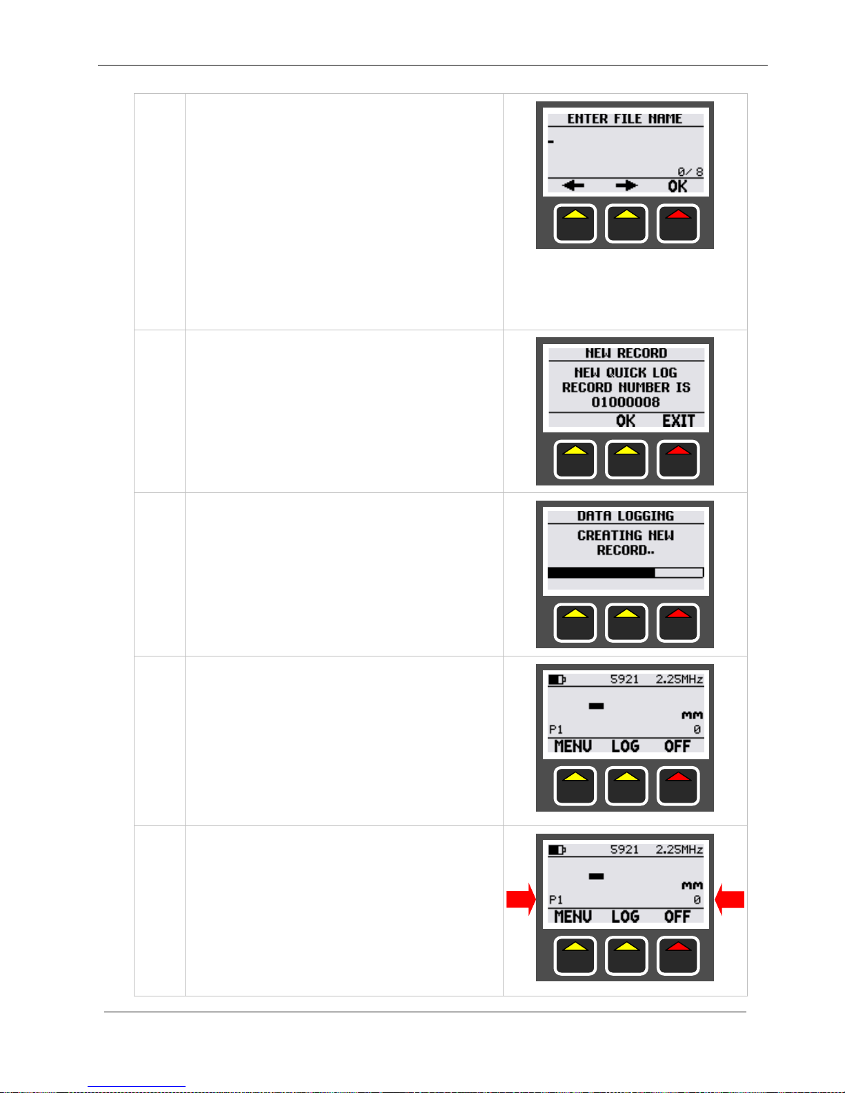
Creating a Quick Log Record File
1.
Press the MENU key to display
the MAIN MENU
2.
DATALOGGING should be
highlighted – press OK
3.
Scroll down to NEW RECORD –
press OK
4.
QUICK LOG should be
highlighted – press OK
Page 51
M4-CYG3-M-ENG_Iss2.doc
Cygnus 3 Operating Manual
51
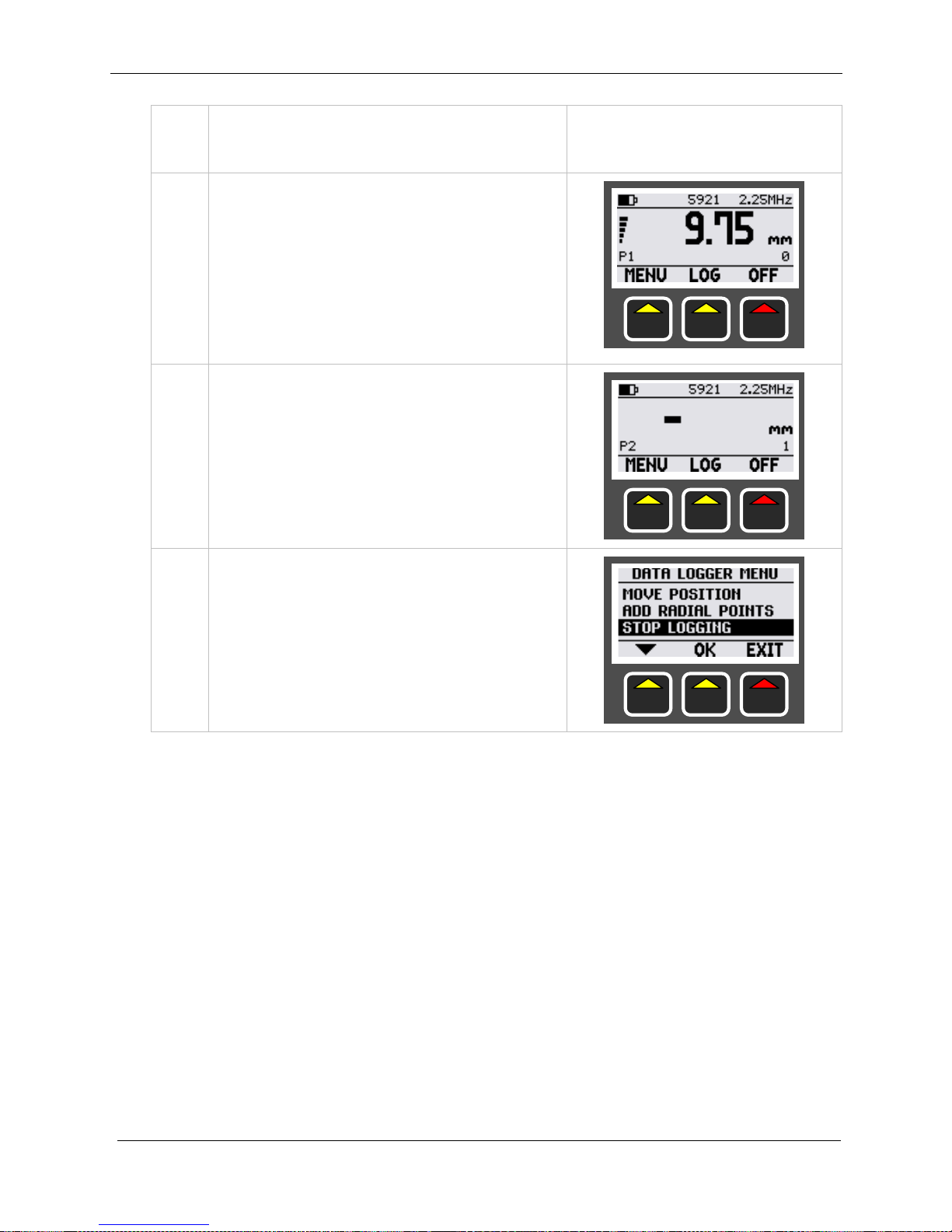
5a.
If Auto-Filename is turned off
then you must t
ype in a filename
for the new record (up to 8
characters maximum)
(If the filename already exists
the user will be prompted to
enter another)
Press OK when done
5b.
If Auto-Filename is turned on
then you need only confirm the
filename created by the gauge
by pressing the OK key
6.
The new blank record is created.
A bar-graph shows the progress
7.
The gauge is now ready to start
logging thickness measurement
results
Note the middle function key is
now LOG – this key is used to
log the thickness measurement.
8.
The number of thickness
measurements that have been
logged is shown on the right of
the screen
The name of the current
measurement point is shown on
Page 52
Cygnus 3 Operating Manual
M4-CYG3-M-ENG_Iss2.doc
52
the left, i.e. “P1” for Point 1.
9.
To log the displayed thickness
measurement press the LOG key
The gauge will give a BEEP and
the display will flash-black.
When the data has been saved
the green LED will flash.
10.
The gauge is now waiting for the
next thickness measurement.
Note the number of logged
measurements and next point
name have moved on.
11.
When all the thickness
measurements points have been
logged close the record by
selecting STOP LOGGING from
the DATA LOGGER MENU (see
page
61)
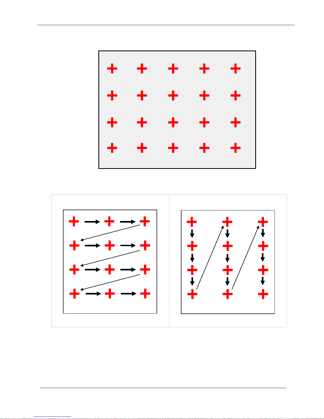
Grid Point Record Files
Grid Point record files are used to organise thickness
measurements across a two dimensional grid. The grid can be
applied to flat plate or cylinders alike.
Page 53
M4-CYG3-M-ENG_Iss2.doc
Cygnus 3 Operating Manual
53
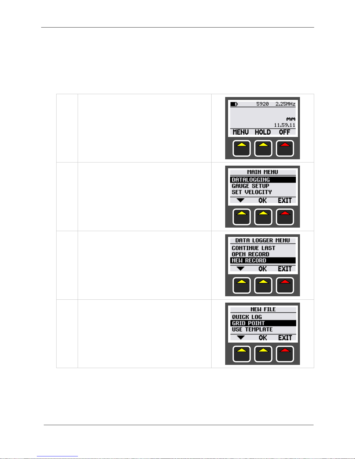
You can also choose which direction measurements will be taken:
Across then Down (ATD)
Down then Across (DTA)
When a Grid Point record is created the measurement point names
are assigned as follows:
1. ROW1 COL1
2. ROW1 COL2
8.6
8.5
8.5
8.4
8.7
8.6
8.7
8.5
8.6
8.5
8.4
8.3
8.5
8.7
8.6
8.5
8.4
8.5
8.4
8.4
Columns across 1..50
Rows
Down
1..100
Page 54
Cygnus 3 Operating Manual
M4-CYG3-M-ENG_Iss2.doc
54
3. ROW1 COL3 etc.
The maximum number of rows and columns is 50 columns and
100 rows.
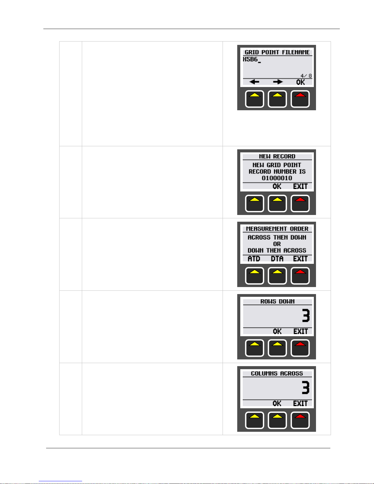
Creating a Grid Point Record File
1.
Press the MENU key to display
the MAIN MENU
2.
DATALOGGING should be
highlighted – press OK
3.
Scroll down to NEW RECORD –
press OK
4.
Scroll down to GRID POINT –
press OK
Page 55
M4-CYG3-M-ENG_Iss2.doc
Cygnus 3 Operating Manual
55
5a.
If Auto-Filename is turned off
then you must type
in a filename
for the new record (up to 8
characters maximum)
(If the filename already exists
the user will be prompted to
enter another)
Press OK when done
5b.
If Auto-Filename is turned on
then you need only confirm the
filename created by the gauge
by pressing the OK key
6.
Next choose the required
measurement direction (see
page
54)
7.
Next enter the number of Rows
down your grid
Maximum = 100
8.
Next enter the number of
Columns across your grid
Maximum = 50
Page 56
Cygnus 3 Operating Manual
M4-CYG3-M-ENG_Iss2.doc
56
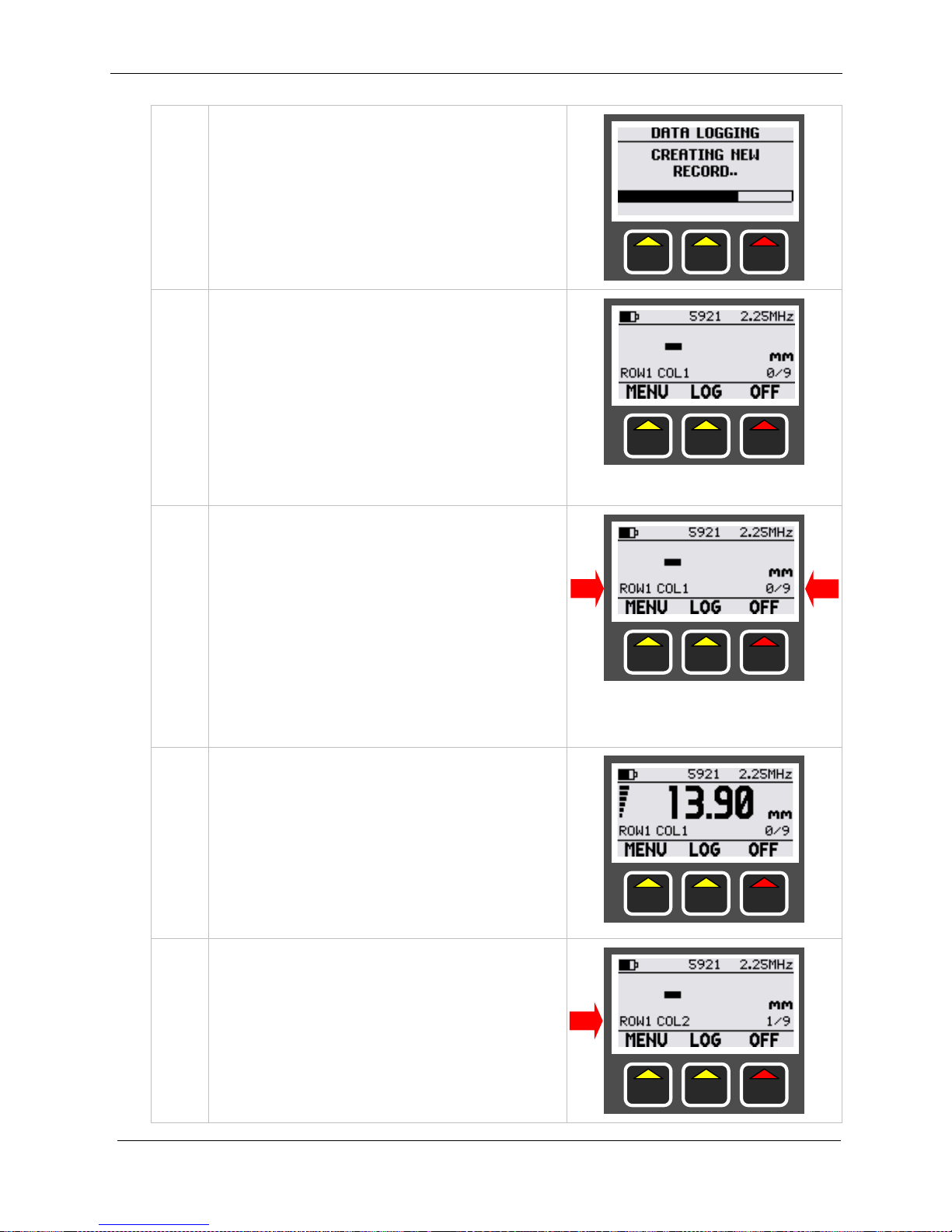
9.
The new Grid Point record file is
now created
10.
The gauge is now ready to start
logging thickness measurement
results
Note the middle function key
name is now LOG – this key is
used to log the thickness
measurement.
11.
The number of thickness
measurements that have been
logged is shown on the right of
the screen followed by the total
number required in your grid.
The name of the current
measurement point is shown on
the left
12.
To log the displayed thickness
measurement press the LOG key
The gauge will give a BEEP and
the display will inverse. When
the data has been saved the
green LED will flash
13.
The gauge is now waiting for the
next thickness measurement
The name of the current
measurement point has moved
to the next grid point location
Page 57
M4-CYG3-M-ENG_Iss2.doc
Cygnus 3 Operating Manual
57
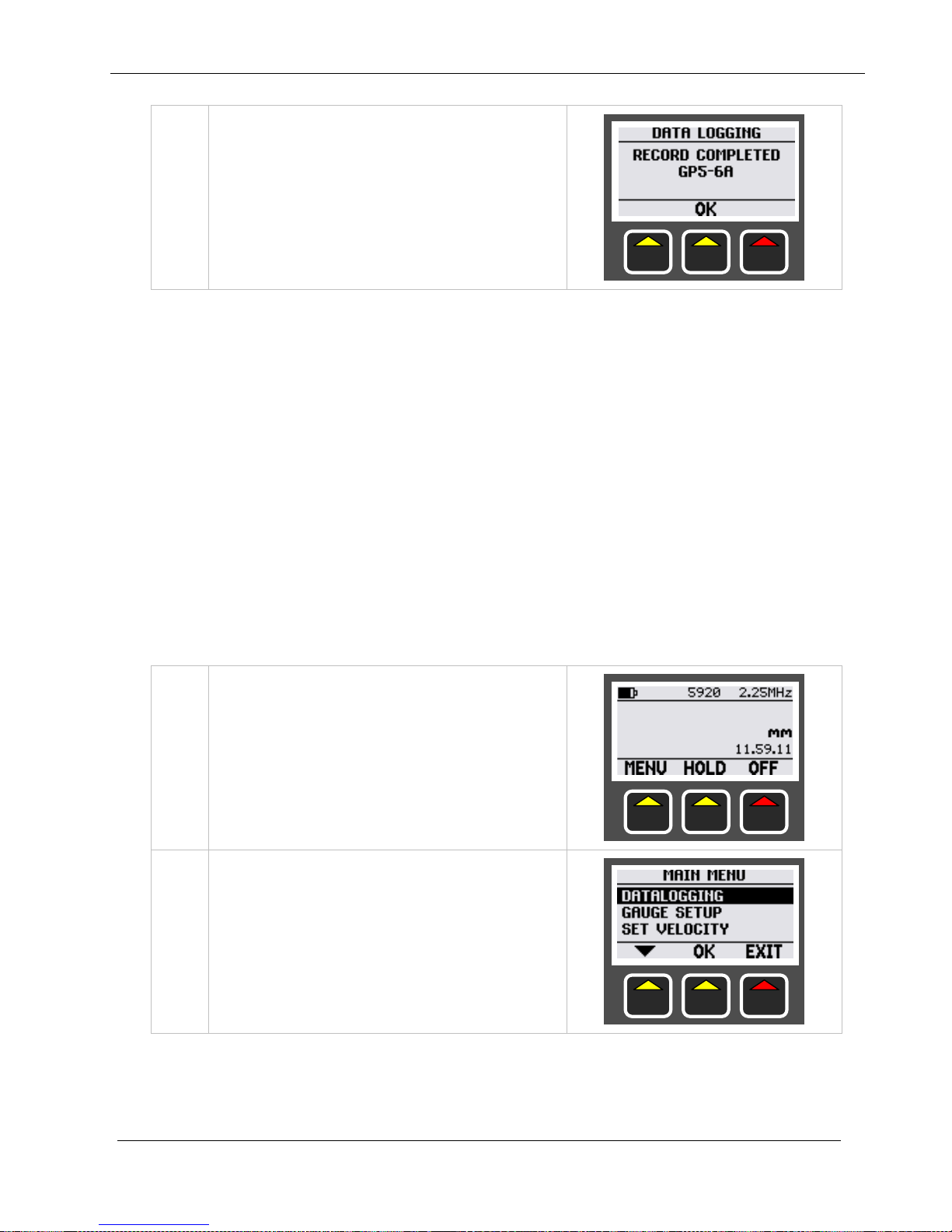
14.
When the last grid point
measurement has been entered
a message alerts the user the
record has been completed.
Press OK.
Template Record Files
Template Files are created on a computer and describe the whole
thickness measurement survey, defining each measurement point
along with a name, reference thickness, minimum thickness and
destination cell in a spreadsheet. Additional information can also
be specified with 40 User Fields that can be used to prompt the
user when each survey begins. Template Files are normally
created to cover a specific type of survey and the actual Template
File would be distributed to all the Cygnus 3 gauges in use within
your company.
Read more about creating Template Files on page 81.
Creating a Record File from a Template
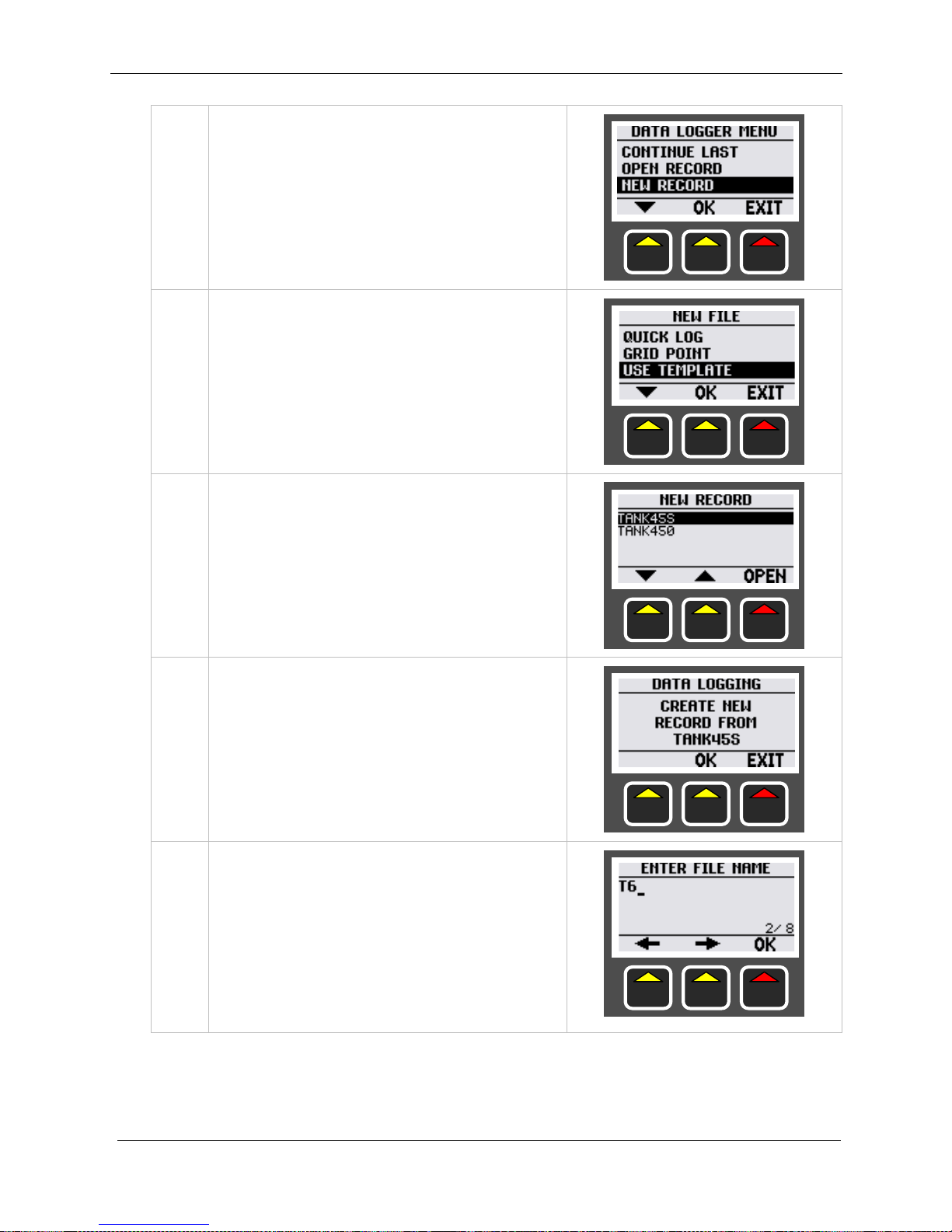
1.
Press the MENU key to display
the MAIN MENU
2.
DATALOGGING should be
highlighted – press OK
Page 58
Cygnus 3 Operating Manual
M4-CYG3-M-ENG_Iss2.doc
58
3.
Scroll down to NEW RECORD –
press OK
4.
Scroll down to USE TEMPLATE –
press OK
5.
Next scroll to select the required
Template File – then press OPEN
6.
Confirm Yes or No
7.
Next enter in a file name for the
new record file (up to 8
characters)
(If the filename already exists
the user will be prompted to
enter another)
Page 59
M4-CYG3-M-ENG_Iss2.doc
Cygnus 3 Operating Manual
59
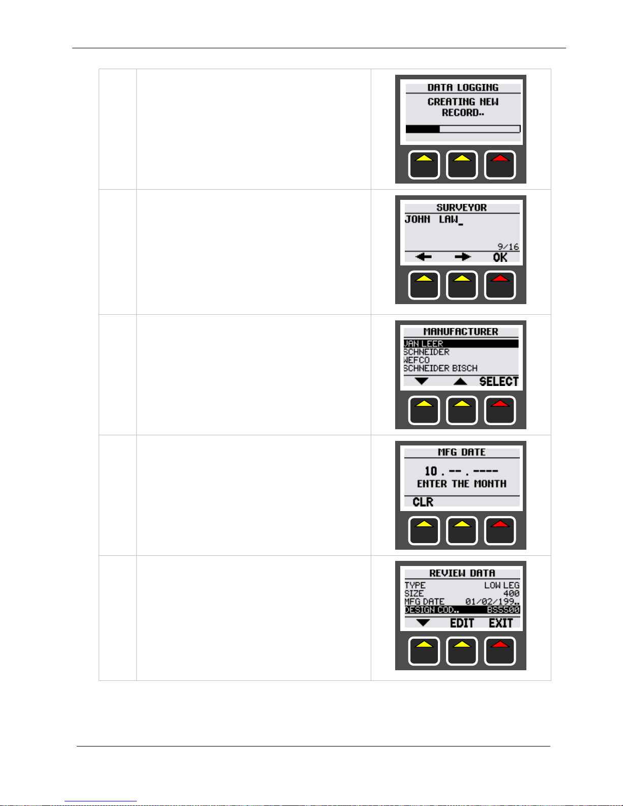
8.
The blank record file is now
created
This process may take a few
seconds to complete
9.
If the template has any of the
40 User Fields specified then the
user will be prompted to enter in
data for each field.
For example
the Surveyor’s name..
10.
pick the Manufacturer from a list
of names..
Scroll to the required name then
press SELECT.
11.
enter the Manufacture Date..
12.
When all the User Fields have
been entered you have the
option to review them and make
any corrections if you need to.
When correct press the EXIT key
to continue.
Page 60
Cygnus 3 Operating Manual
M4-CYG3-M-ENG_Iss2.doc
60
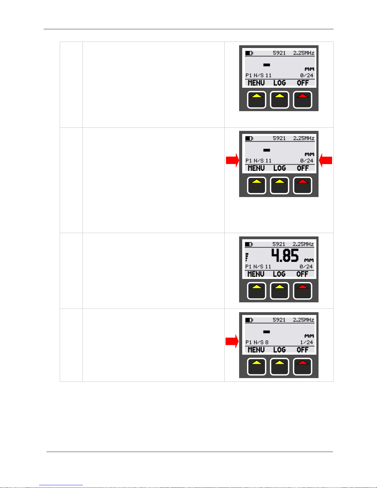
13.
The gauge is now ready to start
logging thickness measurement
results
Note the middle function key
name is now LOG – this key is
used to log the thickness
measurement.
14.
The number of thickness
measurements that have been
logged is shown on the right of
the screen followed by the
number required in the
template.
The name of the current
measurement point is shown on
the left
15.
To log the displayed thickness
measurement press the LOG key
The gauge will give a BEEP and
the display will inverse. When
the data has been saved the
green LED will flash
16.
The gauge is now waiting for the
next thickness measurement
The name of the current
measurement point has moved
to the next location
Page 61
M4-CYG3-M-ENG_Iss2.doc
Cygnus 3 Operating Manual
61
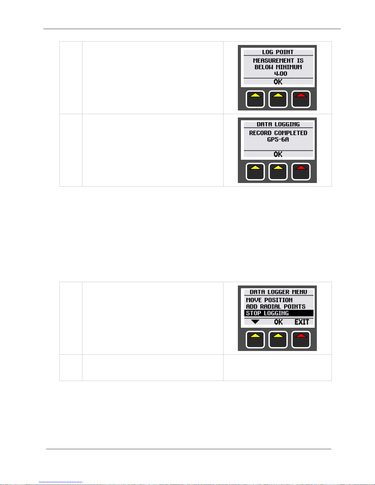
17.
If any logged thickness
measurement is below the
minimum thickness specified the
user is alerted by a message, a
beep and the RED LED is
illuminated
18.
When the last thickness
measurement has been entered
a message alerts the user the
record has been completed.
Press OK.
Data Logging Functions and Management
Stopping, Suspending and Resuming Data Logging
Any Record File can easily be stopped and later resumed. When
data logging is stopped the Gauge will operate as normal except
thickness measurements can’t be logged. When using a Quick Log
Record data logging must be stopped to complete the record, as
there is no pre-set number of measurement points.
1.
To stop or suspend data logging
select STOP LOGGING from the
DATA LOGGER MENU
You will be asked to confirm if
you want to Stop Logging.
2.
Once suspended the gauge can
be used as normal
Page 62
Cygnus 3 Operating Manual
M4-CYG3-M-ENG_Iss2.doc
62
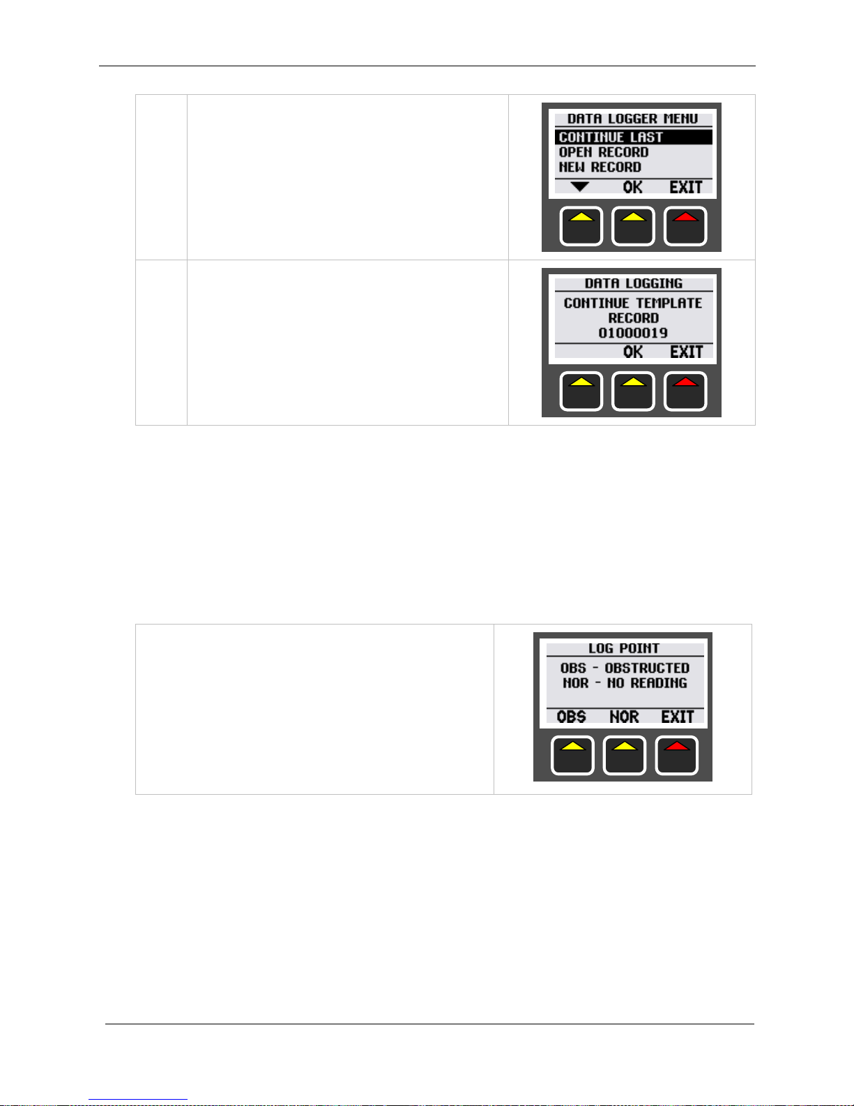
3.
To resume the last record file
select CONTINUE LAST from the
DATA LOGGER MENU
4.
Confirm OK or EXIT
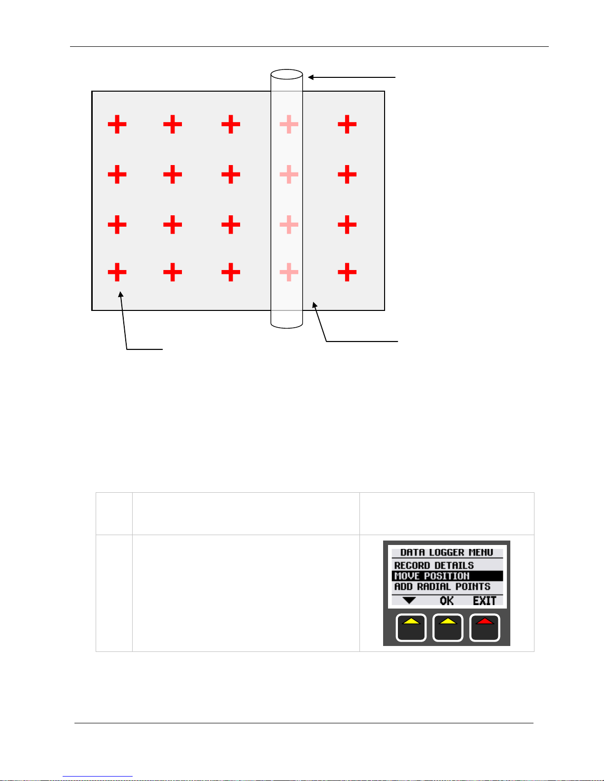
Logging an Obstruction or No-Reading Point
When surveying there may be measurement points that are
inaccessible due to an object being in the way or there may be
points where thickness reading s can’t be obtained (due to
excessive corrosion for example). The Gauge allows the user to
record either a No-Readi ng or Obst r u cted measurement point as
required.
Pressing the LOG key when no
thickness value is displayed gives
the option to select either an
Obstruction or a No-Reading or Exit
to cancel.
Page 63
M4-CYG3-M-ENG_Iss2.doc
Cygnus 3 Operating Manual
63
Moving Position in the current Record File
While data logging, the position where the next thickness
measurement will be saved can be moved back to overwrite an
existing value. It is not possible to move forward beyond the last
thickness measurement logged.
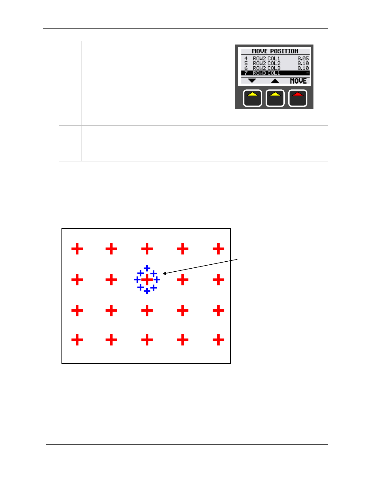
1.
To move position the gauge
must be in data logging mode.
2.
To move position select MOVE
POSITION from the DATA
LOGGER MENU
Obstruction
preventing access to
measurement points.
plate
8.6
8.5
8.5
OBS
8.7
8.6
8.7
8.5
OBS
8.5
8.4
NOR
8.5
OBS
8.6
NOR
8.4
8.5
OBS
8.4
Measurement points
logged as Obstructed
(OBS)
Measurement point
logged as No-reading
(NOR)
Page 64
Cygnus 3 Operating Manual
M4-CYG3-M-ENG_Iss2.doc
64
3.
Use the arrow keys to move the
highlight bar to the
position/measurement value to
be overwritten.
Press MOVE when done.
Press any number key to Cancel.
4.
The gauge will continue to log
thickness measurement values
from this point forward.
Adding Additional Measurement Points
When logging thickness measurements on a pipe, tank or plate it
is sometimes necessary to add additional measurement points
radially around a badly corroded or thin point to detail the extent
of the thinning or corrosion.
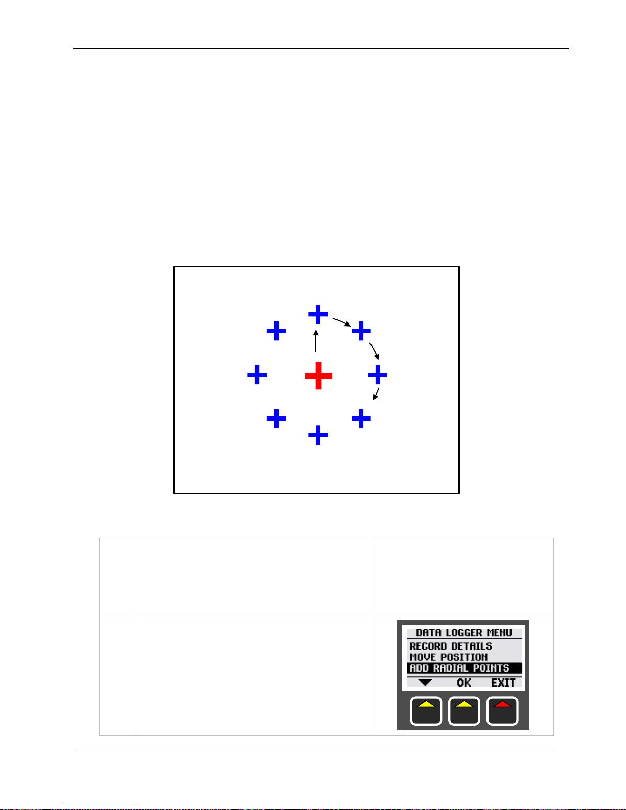
For Quick Log and Grid Point records the Gauge has a facility to
add 4 to 12 additional radial measurement points linked to the
measurement just taken. When additional radial points are added
the parent point name is suffixed with A, B, C, D etc. linking the
radial points to the parent thickness measurement.
8 additional radial
measurement points.
plate
Page 65
M4-CYG3-M-ENG_Iss2.doc
Cygnus 3 Operating Manual
65
Example:
Parent Thickness Point Name = P8
Radial Point 1 Name = P8A
Radial Point 2 Name = P8B
Radial Point 3 Name = P8C
Radial Point 4 Name = P8D
Radial Point 5 Name = P8E
Radial Point 6 Name = P8F
Radial Point 7 Name = P8G
Radial Point 8 Name = P8H
How to add Additional Radial Points
1.
To add Radial Points the gauge
must be in logging mode with
either a Quick Log or Grid Point
record
2.
Select ADD RADIAL POINTS from
the DATA LOGGER MENU
plate
P8
P8A
P8B
P8C
P8D
P8E
P8F
P8G
P8H
Page 66
Cygnus 3 Operating Manual
M4-CYG3-M-ENG_Iss2.doc
66
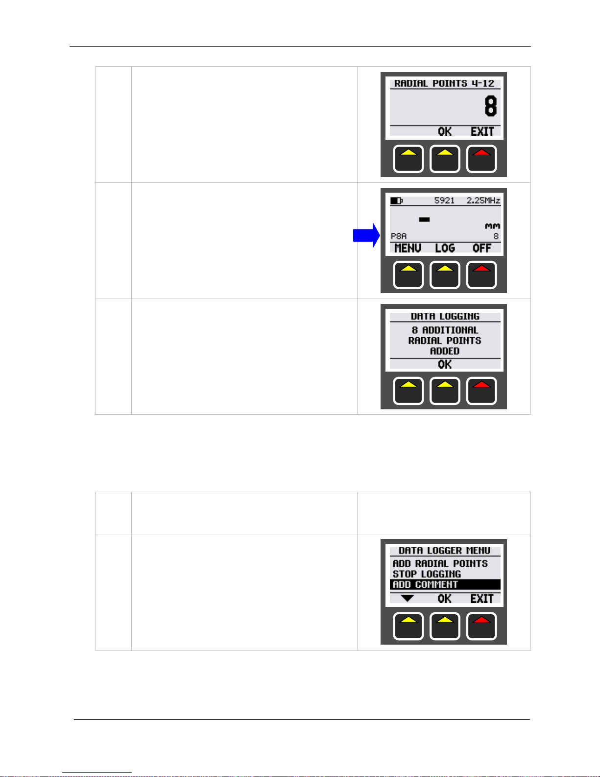
3.
Enter in the number of additional
points required, from 4 to 12.
Then press OK
4.
The gauge is ready to start
logging the additional thickness
values
Note the measurement point
names have suffix A, B, C etc.
5.
Once all the additional points
have been logged a message
alerts the user
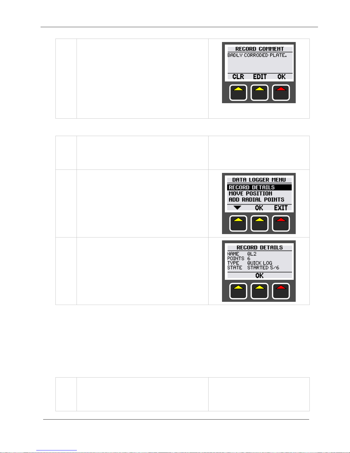
Adding a Comment while Data Logging
A text comment can be added to the current Record File. This
comment will be included in the report printout.
1.
To add a comment the gauge
must be in logging mode
2.
Select ADD COMMENT from the
DATA LOGGER MENU
Page 67
M4-CYG3-M-ENG_Iss2.doc
Cygnus 3 Operating Manual
67
3.
The current text comment is
displayed if there already is one.
To edit this comment or add a
new one press the EDIT key.
To remove the comment press
the CLR key
Displaying the Current Record File Details
1.
To view the record details the
gauge must be in data logging
mode.
2.
To view record details select
RECORD DETAILS from the
DATA LOGGER MENU
3.
The screen shows the record
details. Press OK to close.
Reviewing Template File User Fields
When a Record File has been created using a Template File there
may be up to 40 user fields contained in the record. Normally
these User Fields will have been completed when the Record File
was created but this data can also be viewed and edited while the
record file is open.
1.
To view the User Field data the
gauge must be in logging mode
with a Template record file
Page 68
Cygnus 3 Operating Manual
M4-CYG3-M-ENG_Iss2.doc
68
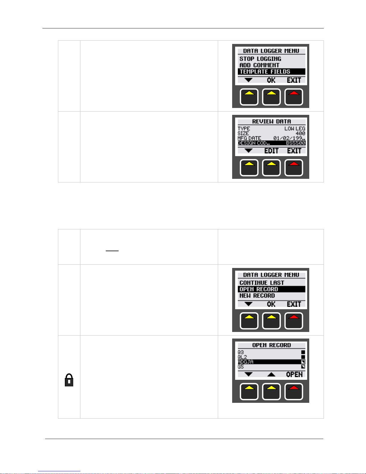
2.
Select TEMPLATE FIELDS from
the DATA LOGGER MENU
3.
The current values are
displayed.
To edit scroll to the required
field and press the EDIT key.
Opening a Record File
An existing Record File can be opened to continue data logging
from the last position.
1.
To open a record file the gauge
must not be in data logging
mode.
2.
To open a record file select
OPEN RECORD from the DATA
LOGGER MENU
3.
The screen shows a list of record
files. Scroll to the record to open
and press the OPEN key.
Padlock icon = protected
Empty box = empty record
Half box = started record
Black box = complete record
Page 69
M4-CYG3-M-ENG_Iss2.doc
Cygnus 3 Operating Manual
69
4.
Note. Protected records can’t be
opened.
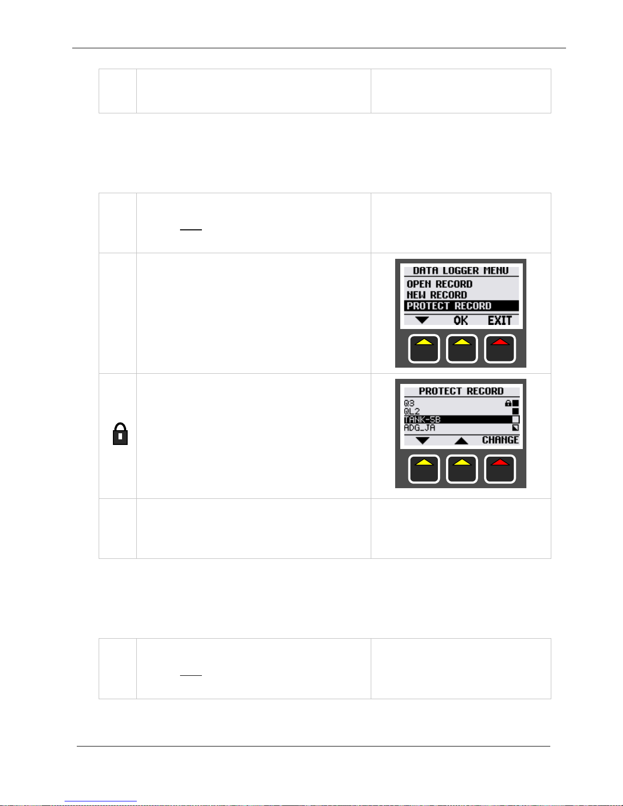
Protecting Record Files
Record Files can be locked to prevent de le t ion or any accidental
changes being made.
1.
To protect record files the gauge
must not be in data logging
mode.
2.
To protect a record file select
PROTECT RECORD from the
DATA LOGGER MENU
3.
The screen shows a list of all the
record files.
Padlock icon = protected
Empty box = empty record
Half box = started record
Black box = complete record
4.
To change the protection scroll
to the record file to change and
press the CHANGE key
Deleting Record Files
Un-protected Record Files can be deleted from the Gauge’s
memory. Template Files are not deleted.
1.
To delete record files the gauge
must not be in data logging
mode.
Page 70
Cygnus 3 Operating Manual
M4-CYG3-M-ENG_Iss2.doc
70
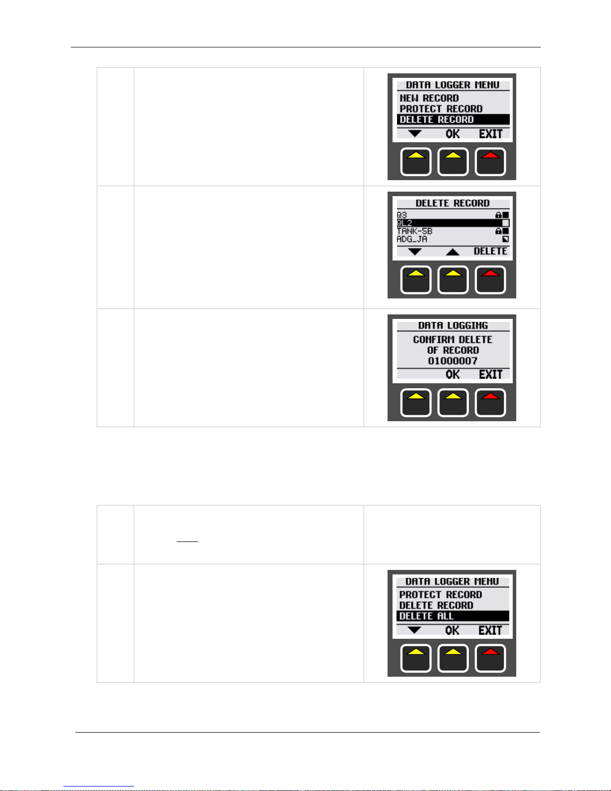
2.
To delete a record file select
DELETE RECORD from the DATA
LOGGER MENU
3.
The screen shows a list of all the
record files.
Padlock icon = protected
Empty box = empty record
Half box = started record
Black box = complete record
4.
To delete scroll to the record file
and press the DELETE key
Confirm OK or EXIT
Deleting all Record Files
Un-protected Record Files can be deleted from the Gauge’s
memory in one step. Template Files are not deleted.
1.
To delete record files the gauge
must not be in data logging
mode.
2.
To delete a record file select
DELETE ALL from the DATA
LOGGER MENU
Page 71
M4-CYG3-M-ENG_Iss2.doc
Cygnus 3 Operating Manual
71
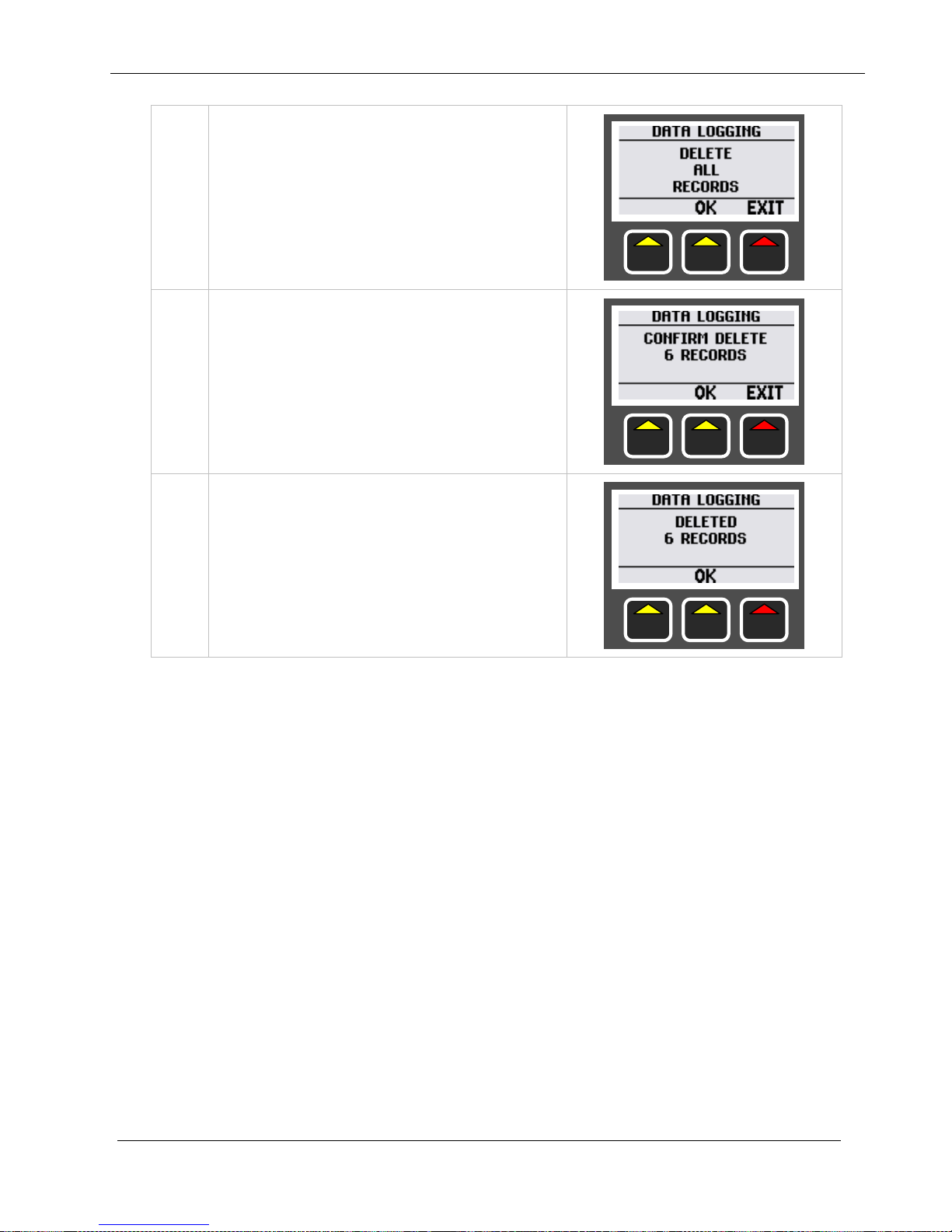
3.
Confirm OK or EXIT
4.
Confirm OK or EXIT again
5.
The number of records deleted
will be shown
Changing the Velocity or Calibration while Data Logging
While data logging the velocity of sound or the calibrat i on can’t be
changed.
When a Record File is created the current velocity value is copied
into the record file, the velocity value is then locked while data
logging. The velocity value will be included in the report print out.
Auto-Log Function
The Auto-Log function will automatically ‘LOG’ thickness
measurements to the current record file each time the probe is
coupled and a valid and stable thickness measurem ent is tak en
and held.
This feature can speed up data logging as you don’t need to keep
pressing the LOG key each time enabling you to quickly progress
along the object being surveyed.
Page 72
Cygnus 3 Operating Manual
M4-CYG3-M-ENG_Iss2.doc
72
Sometimes however you may need the flexibility to choose when
to ‘LOG’ the thickness measurement, so the Auto-Log function is
not required.
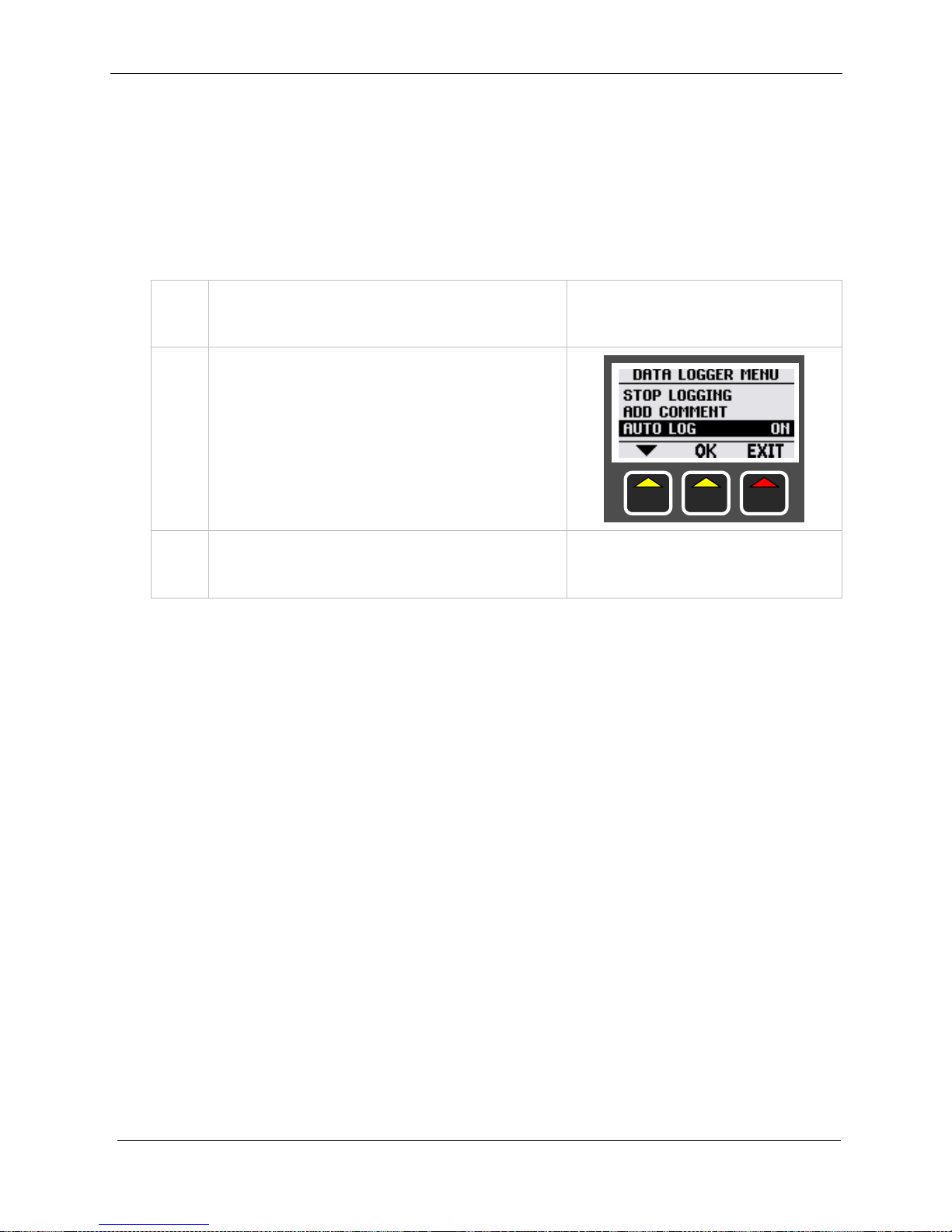
You can turn the Auto-Log function on or off as required from the
Data Logging Menu when data logging.
1.
The gauge must be in data
logging mode.
2.
To change the Auto-Log feature
scroll down to the AUTO L OG
item in the DATA LOGGER
MENU.
3.
Press the OK key to change the
value.
Using the Auto Log Feature
The Auto Log feature requires the user to position, hold and move
the probe in a certain time for it to automatically log the thickness
values, follow this pattern to auto log the thickness points;
1. Place the probe on the surface to be measured until you get a
thickness reading that is stable.
2. Hold the probe, and the thickness measurement until you get
a beep and the screen signals the measurement has been
logged – look for the green LED to light.
3. Release the probe and don’t attempt another measurement
for 1 second minimum.
4. Repeat from step 1 again.
Page 73

M4-CYG3-M-ENG_Iss2.doc
Cygnus 3 Operating Manual
73
9. Cygnus 3 Data Logger Manager
Overview
The Cygnus 3 Data Logger Manager is a Windows® application for
managing the records on a Cygnus 3 Gauge. It provides the
following functions:
1. Transfer of Record Files from Gauge to comput er
2. Creation of thickness survey reports for printing (or PDF)
3. Creation of Template Files
4. Transfer of Template Files from computer to Gauge
It provides a simple intuitive interface for managing your thickness
survey data and creating reports and templates.
Installation
The installation of the Cygnus 3 Data Logger Manager application
is simple and straightforward. The application does however
require the ‘Windows
®
.NET’ framework to be installed but this is
included in the installation package provided in the gauge kit so
additional downloading should not be required.
To start installing insert the supplied CD and either choose to
install the Cygnus 3 Data Logger Manager from the menu or locate
the setup.exe file on the CD and open it. A ‘Welcome’ install
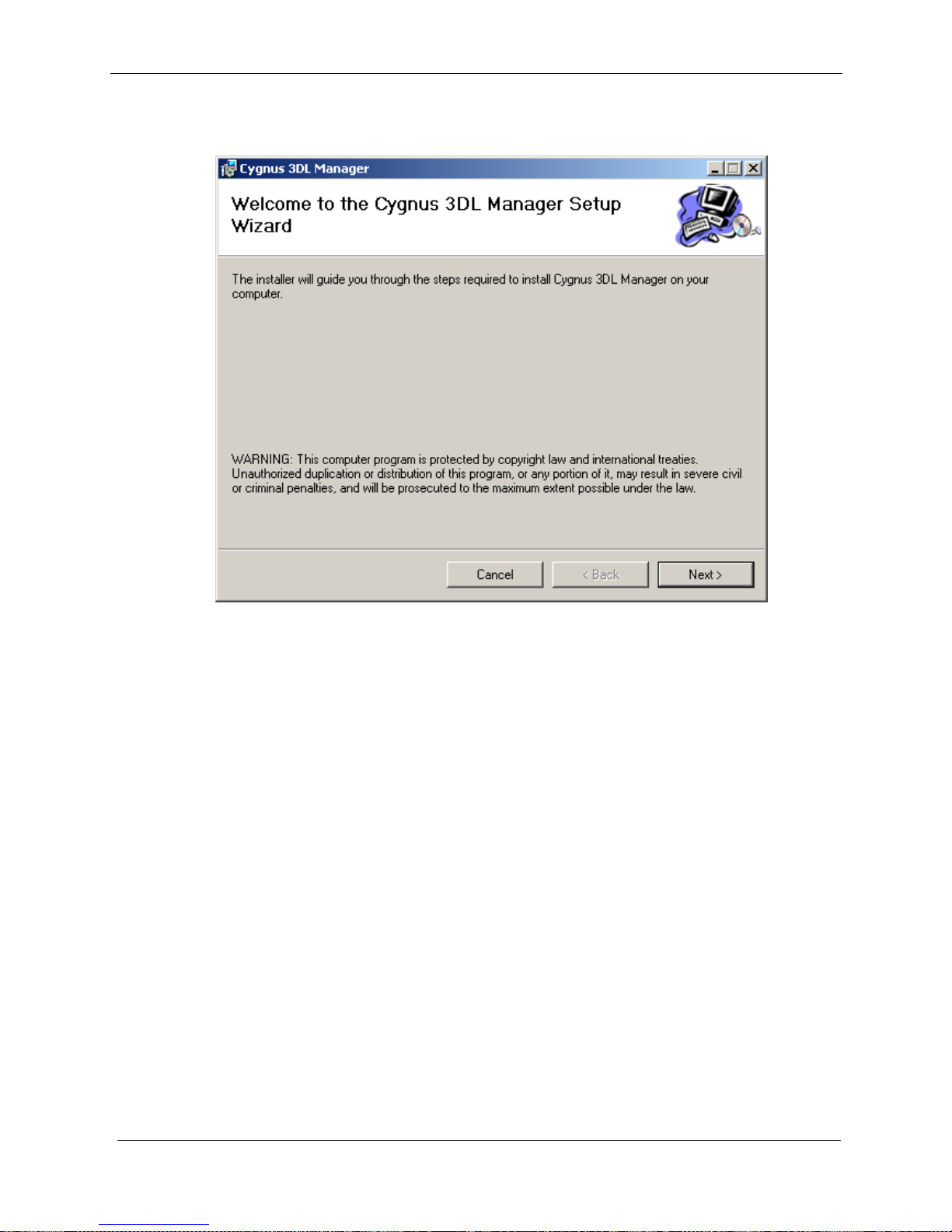
screen is displayed, shown in Fig. 9.1. Follow the instructions and
allow the application to install. A desktop icon will be created along
with a program folder.
If the .NET framework needs to be installed the CD Installer
Package will automatically start this installation.
To run Cygnus 3 Data Logger Manager double click the desktop
icon:
Page 74
Cygnus 3 Operating Manual
M4-CYG3-M-ENG_Iss2.doc
74
Fig 9.1 ‘Welcome’ Install Screen
Connecting the Data Logger to the Computer
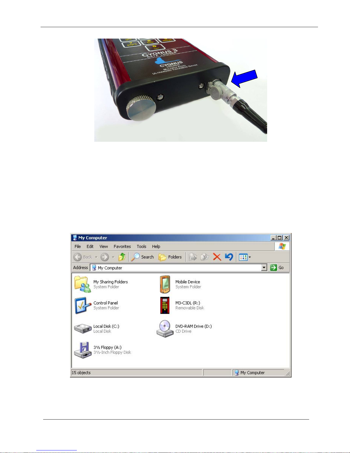
The Gauge is connected to any free USB port on the computer or
USB Hub with the special cable supplied (Note this is not a
standard USB cable as it has a ‘Lemo 0’ connector at the Gauge
end). The USB connector on the Gauge is located on the bottom
plate opposite the battery screw, it is covered by a hinged dust
cover shown below in Fig 9.2
Page 75
M4-CYG3-M-ENG_Iss2.doc
Cygnus 3 Operating Manual
75
Fig 9.2 Gauge USB Connection
When the Gauge is connected to the computer and the USB link
has been established the screen on the Gauge will display “USB
CONNECTED” and the backlight will be turned off.
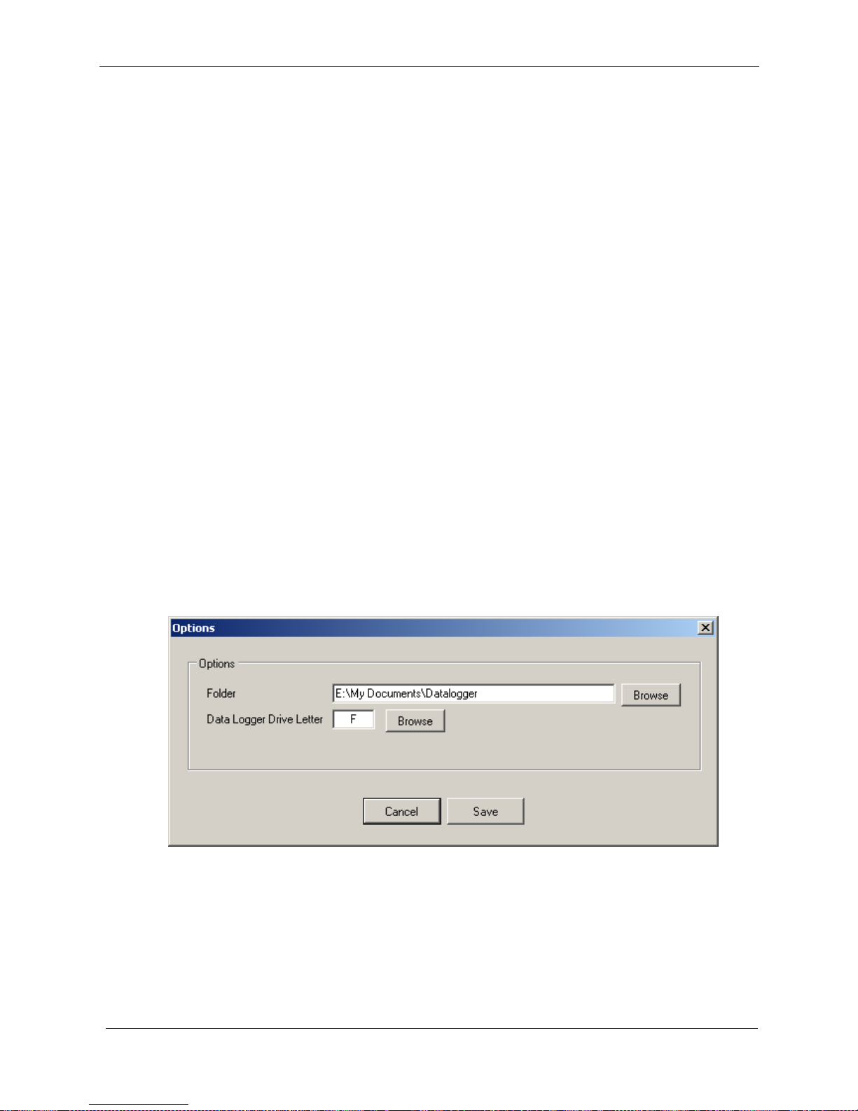
On the computer the Gauge will be shown as a new ‘Removable
Disk’ when viewing ‘My Computer’ as shown below in Fig 9.3. (On
the computer click ‘Start’ then ‘My Computer’).
Fig 9.3 ‘My Computer’ (Windows XP)
Page 76
Cygnus 3 Operating Manual
M4-CYG3-M-ENG_Iss2.doc
76
Setting Options
When the Gauge is connected to the computer you must
determine the drive letter that Windows
®
has assigned for the
Gauge. In Fig. 9.3 above the drive letter assigned is ‘R:’.
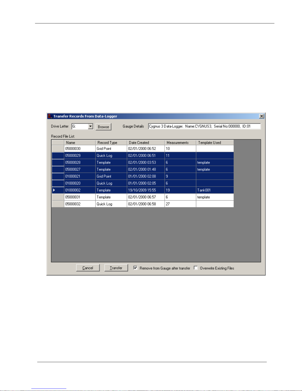
To set this in Cygnus 3 Data Logger Manager menu bar click on
‘File’ then ‘Options’, the dialog box will be displayed as shown in
Fig 9.4. Set the ‘Data Logger Drive Letter’ as required, click
‘Browse’ to check the letter is correct.
The location of the folder that will hold the Record File and
Template Files can also be changed. By default a folder called
‘Datalogger’ is created in the ‘My Documents’ folder
(‘Documents’ on Microsoft Vista). This ‘Datalogger’ folder
contains three sub-folders called:
1. Record Files Folder for Record Files
2. Template Files Folder for Template Files
3. Add-In Fol de r for Ex cel Add-In file
When done click on ‘Save’ to save these settings.
Fig 9.4 Options
Transferring Record Files from the Data Logger
To transfer record files from Gauge to computer, from the Cygnus
3 Data Logger Manager menu bar click ‘Data Logger’ then
Page 77
M4-CYG3-M-ENG_Iss2.doc
Cygnus 3 Operating Manual
77
‘Transfer Records from Gauge’. The ‘Transfer Records from
Data Logger’ dialog box will be displayed, Fig 9.5.
The drive letter should be correct, but it can be changed here
using the drop-down list.
When a Gauge has been detected the Record File List in the dialog
box will populate with all the record files on the Gauge’s memory
card.
Fig 9.5 Transfer Records from Data Logger
Simply select the records to transfer by clicking on their ‘Row
Selectors’ - hold the shift key to select multiple records. Then click
‘Transfer’, the selected record files will then be copied from the
Gauge’s memory card to the computer.
There is also the option to remove the transferred record files from
the Gauge and to overwrite any existing files on the computer.
Page 78
Cygnus 3 Operating Manual
M4-CYG3-M-ENG_Iss2.doc
78
Creating and Printing a Report
Once records have been transferred from the Gauge a report can
be created that can be printed or saved as a PDF (if PDF creation
software has been installed).
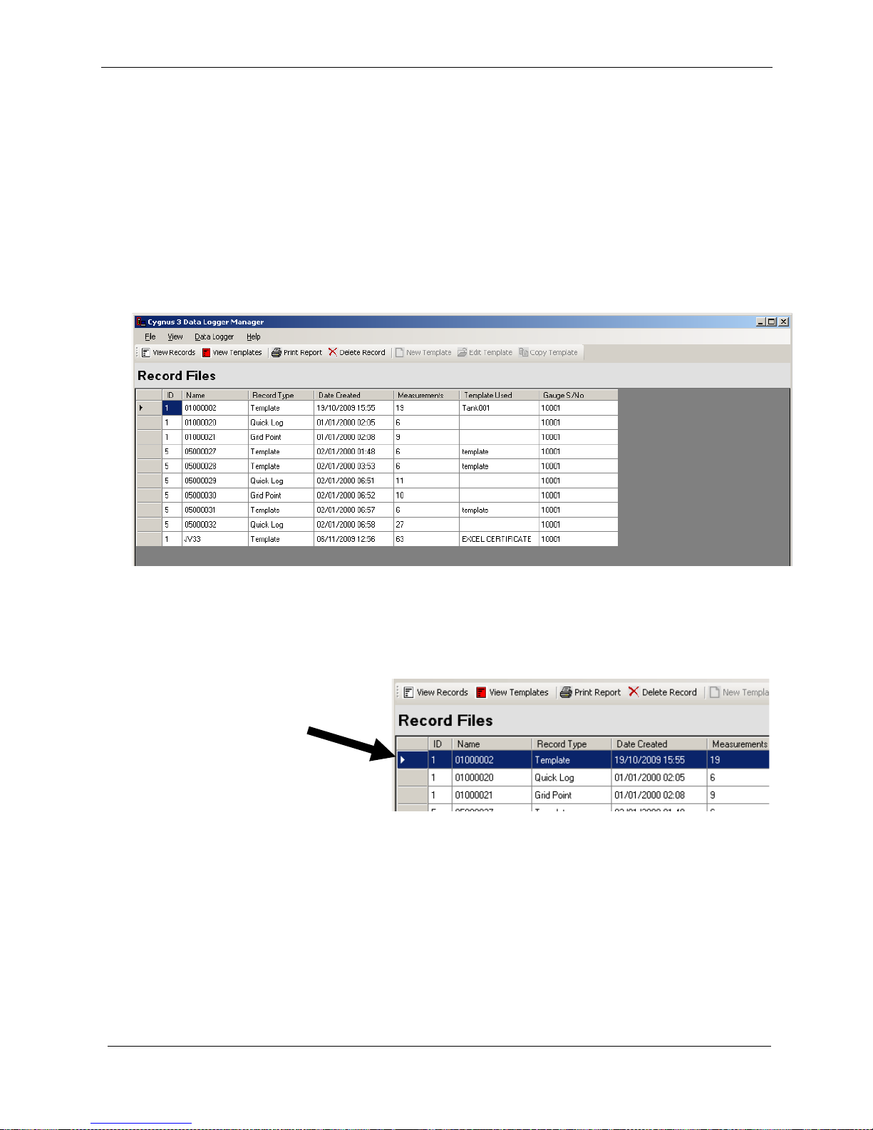
In Cygnus 3 Data Logger Manager click on the ‘View Records’
button and the screen should list all the record files found, shown
below in Fig 9.6.
Fig 9.6 Record Files List
Select a record by clicking the grey ‘Row Selector’ on the left and
then click on the ‘Print Report’ button in the toolbar.
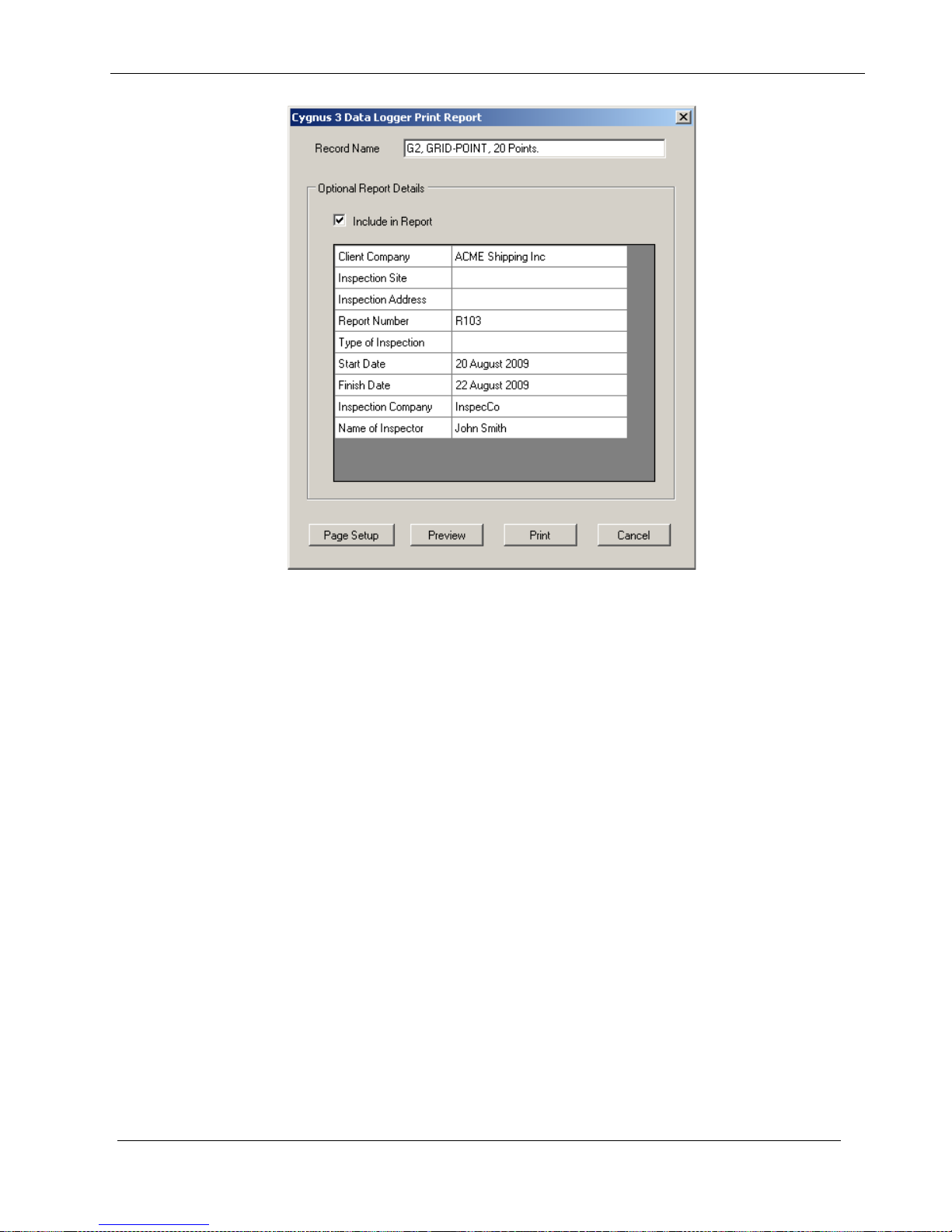
A dialog box is displayed that allows optional report details to be
added at the top of the report when the tick-box ‘Include in
Report’ is checked. See Fig 9.7.
Row Selectors
Page 79
M4-CYG3-M-ENG_Iss2.doc
Cygnus 3 Operating Manual
79
Fig 9.7 Optional Report Details
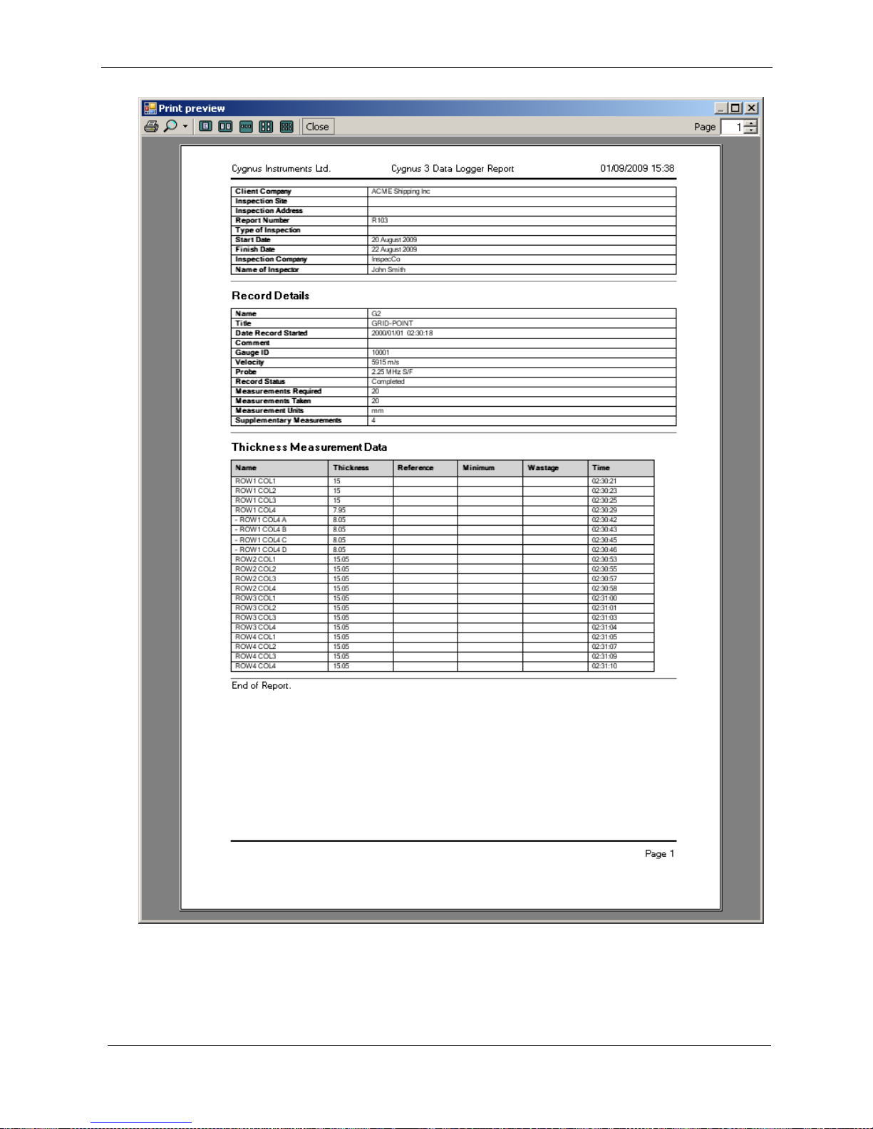
Next click either ‘Preview’ or ‘Print’ as required. Fig 9.8 shows a
typical paper report layout in the Print Preview window.
Page 80
Cygnus 3 Operating Manual
M4-CYG3-M-ENG_Iss2.doc
80
Fig 9.8 Report Layout – Print Preview
Page 81
M4-CYG3-M-ENG_Iss2.doc
Cygnus 3 Operating Manual
81
Deleting a Record File
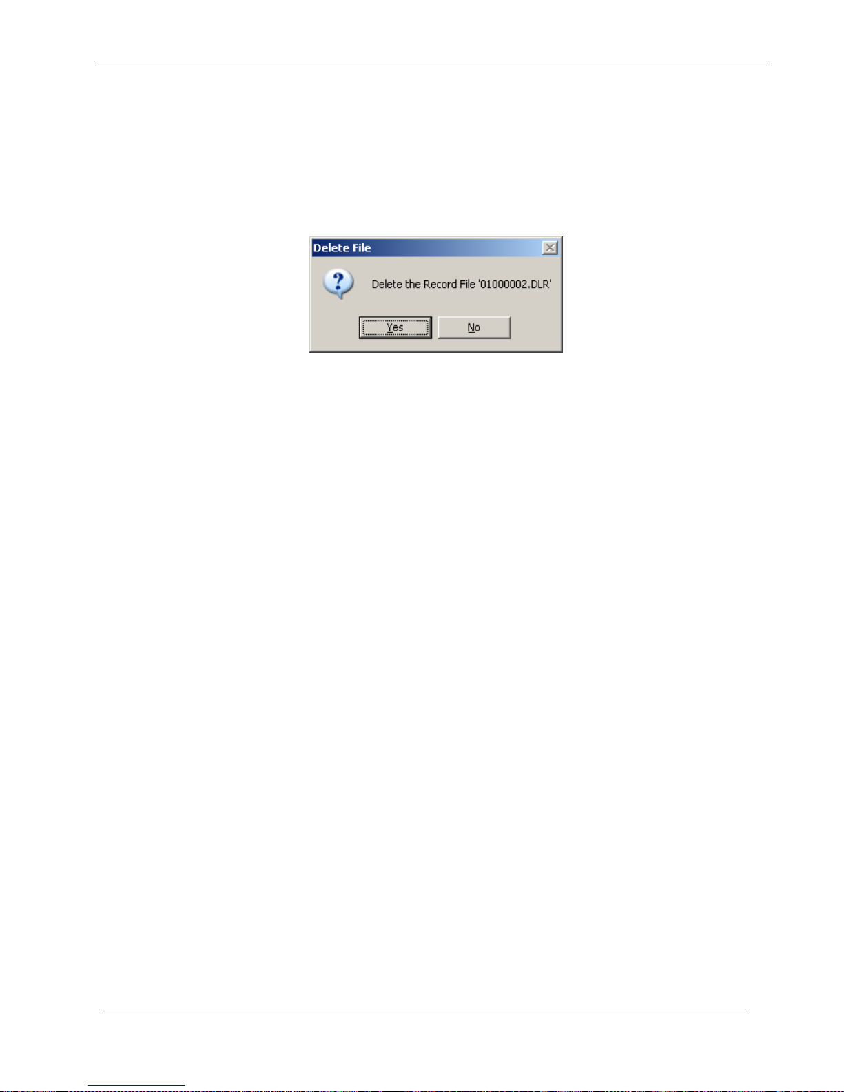
You can delete a Record File from the computer by first clicking on
the row selector of the record you want to delete then clicking the
“Delete Record” button in the toolbar. You must then confirm you
wish to delete this record.
Template Files
Template Files allow structured data logging of thickness
measurements when repeatedly surveying identical or similar
objects. A Template File is first created using Cygnus 3 Data
Logger Manager then the file is copied to each Gauge ready for
use.
The data in a Record File produced from a Template file is intended
to be inserted into an Excel
®
Spreadsheet (or it can just be printed
out in a report) so each piece of da ta has a desti n at ion ce l l
reference – this is the spreadsheet cell the data will be copied into,
i.e. cell ‘D12’.
An XLT file (Excel
®
Template) can be specified to be used as a
template for the Excel document produced. So a compa n y rep ort,
as an XLT file, can be used to create each new blank report
document that will then receive the thickness measurement and
other data collected by the Gauge.
Page 82
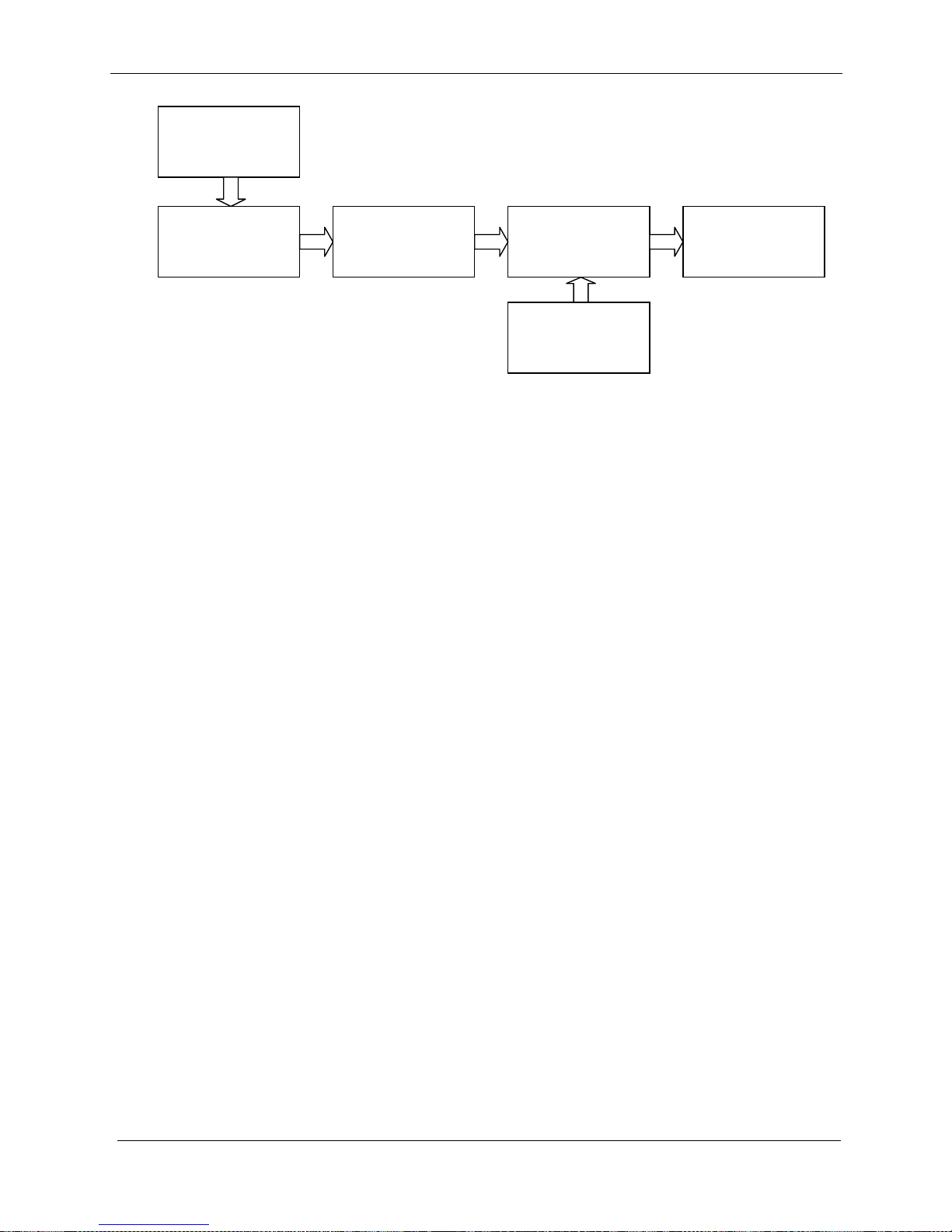
Cygnus 3 Operating Manual
M4-CYG3-M-ENG_Iss2.doc
82
User Fields
Template Files can contain up to 40 User Fields which can be used
to collect extra information from the Gauge user when they start a
new record from a template.
Each User Field can prompt for the following types of data;
1. Alphanumeric i.e. “ABC123”
2. Number i.e. “245.6”
3. Date (dd-mm-yyyy) i.e. “21-07-2008”
4. Date (mm-dd-yyyy) i.e. “07-21-2008”
5. List i.e. “Red, Blue, Yellow, Green..”
6. Yes/No Choice
Each User Field has: a ‘Name’ field, this is used to prompt the
Gauge user to enter in information, and a ‘Value’ field to hold the
information. An optional ‘Cell Ref.’ field to specify where the Value
should be inserted in the spreadsheet.
For example;
If the User Field Type = Alphanumeric
If the User Field Name = ‘Vessel Name’
If the User Field Cell Ref = ‘Sheet 1!E20’
When the Gauge user starts a new record they will be prompted
to enter in a ‘Vessel Name’.
Template
File
Record
File(s)
Gauge
XLT File
New Excel
Report
Finished
Report
Page 83
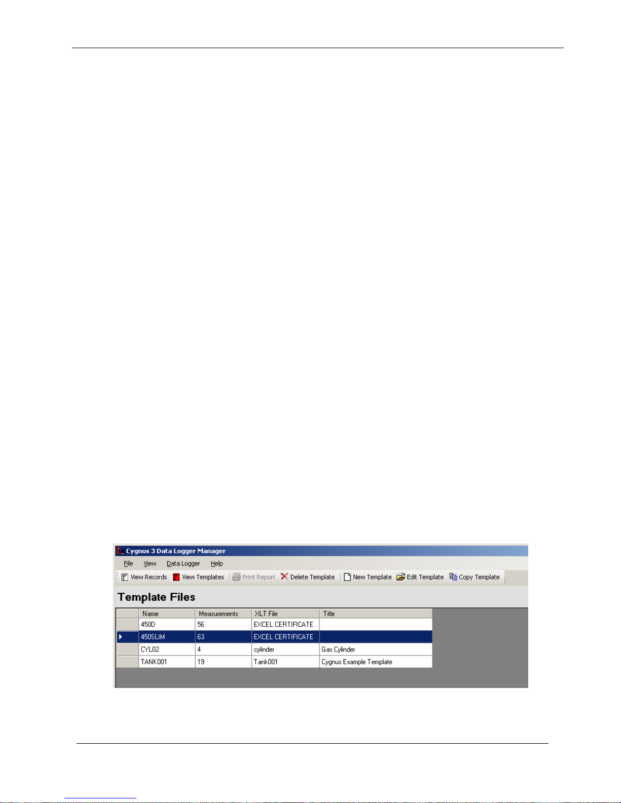
M4-CYG3-M-ENG_Iss2.doc
Cygnus 3 Operating Manual
83
The vessel name the user types in will be stored against the
‘Vessel Name’ field and be included in the report data.
As the ‘cell ref.’ was also specified the vessel name will be
inserted into the spreadsheet report into cell ‘E20’ on ‘Sheet 1’.
See how this appears on the Gauge screen starting on page 57.
User Field ‘List’ Type
When the User Field type is set to List you must provide a list of
text choices that will be presented to the gauge user. This list can
contain up to 40 items of 16 characters in length.
Measurement Points
Template Files contain measurement points for each thickness
measurement required. Each measurement point consists of a
“Name”, a “Reference Thickness”, a “Minimum Thickness”, a “Cell
Reference” and the “Thickness Measurement” itself.
The “Reference” and “Minimum Thickness” are o pt io nal , but w he n
included they allow wastage calculations in reports and minimum
alarm functions when measuring. See minimum alarm function
starting on page 57.
Creating a Template File
From the Cygnus 3 Data Logger Manager click the ‘View
Templates’ button in the menu bar. The screen will display any
existing templates found, shown in Fig 9.9.
Fig 9.9 Template List
Page 84
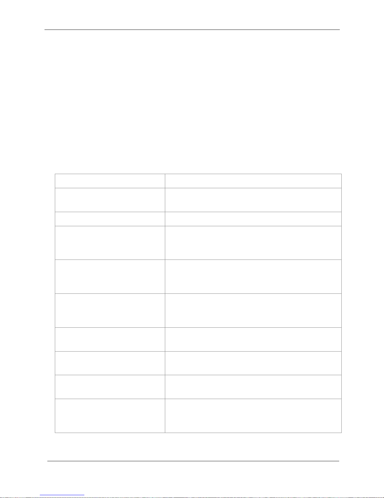
Cygnus 3 Operating Manual
M4-CYG3-M-ENG_Iss2.doc
84
To create a new template click the ‘New Template’ button. A
‘New Template’ dialog box will be displayed, Fig 9.10. Next
choose between the three types of template:
1. Blank Template – just open the template form with blank
fields so you can add your own
2. Single Point Record – a list of measurement points
3. Grid Point Record – a 2D gri d of m ea surement points
This dialog box can help to speed up the creation of Template Files
by creating the measurement points for you, based on the
parameters detailed below.
Template File Name
A filename for the template file
Template Type
Choose the type that suits your
application
Units
Specify the measurement units required
Measurements, Prefix
For a Single Point record specify the
number of measurements required and
the prefix, i.e. P1, P2, P3..
Rows, Prefix
For a Grid Point record specify the
number of Row measurements required
and the prefix, i.e. R1, R2, R3..
Columns, Prefix
For a Grid Point record specify the
number of Column measurements
required and the prefix, i.e. C1, C2, C3..
Minimum Thickness
Specify an optional minimum thickness
value
Reference Thickness
Specify an optional reference thickness
value
Starting Cell Ref.
Specify the starting Excel spreadsheet
cell for the first measurement, i.e. D10
Measurement Order
For a Grid Point record specify the
direction the grid points will be
measured
Page 85
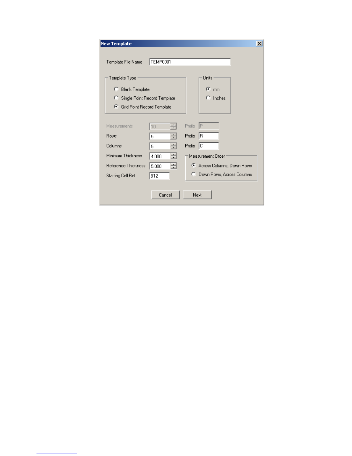
M4-CYG3-M-ENG_Iss2.doc
Cygnus 3 Operating Manual
85
Fig 9.10 New Template dialog
Once completed click the ‘Next’ button.
Template Form
The Template Form is displayed with thickness measurement
points added as selected, shown in Fig 9.11. These thickness
measurement points can be edited as required. Each section is
described in the tables that follow.
The Template Form has three ‘Tabs’ for:
1. Template Details
2. Thickness Measurement Points
3. User Fields
Page 86
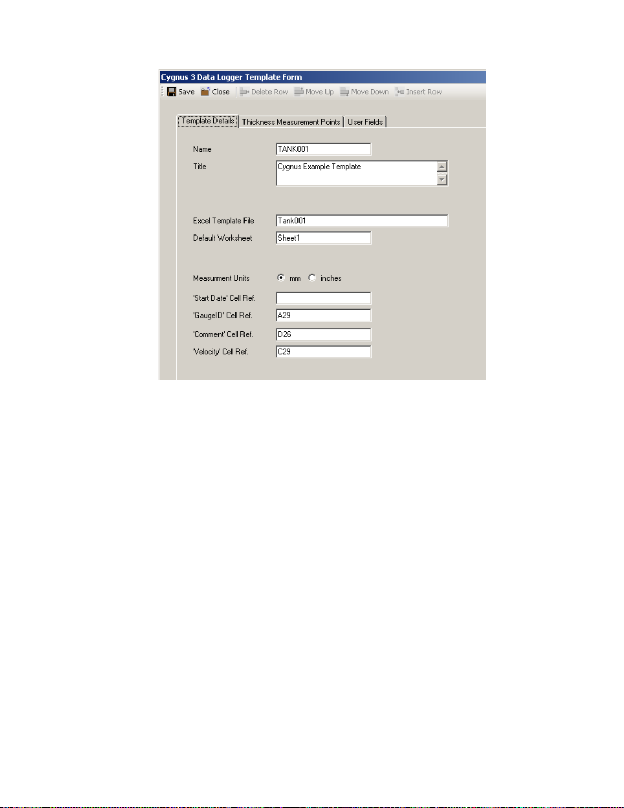
Cygnus 3 Operating Manual
M4-CYG3-M-ENG_Iss2.doc
86
Fig 9.11 Template Form
Page 87
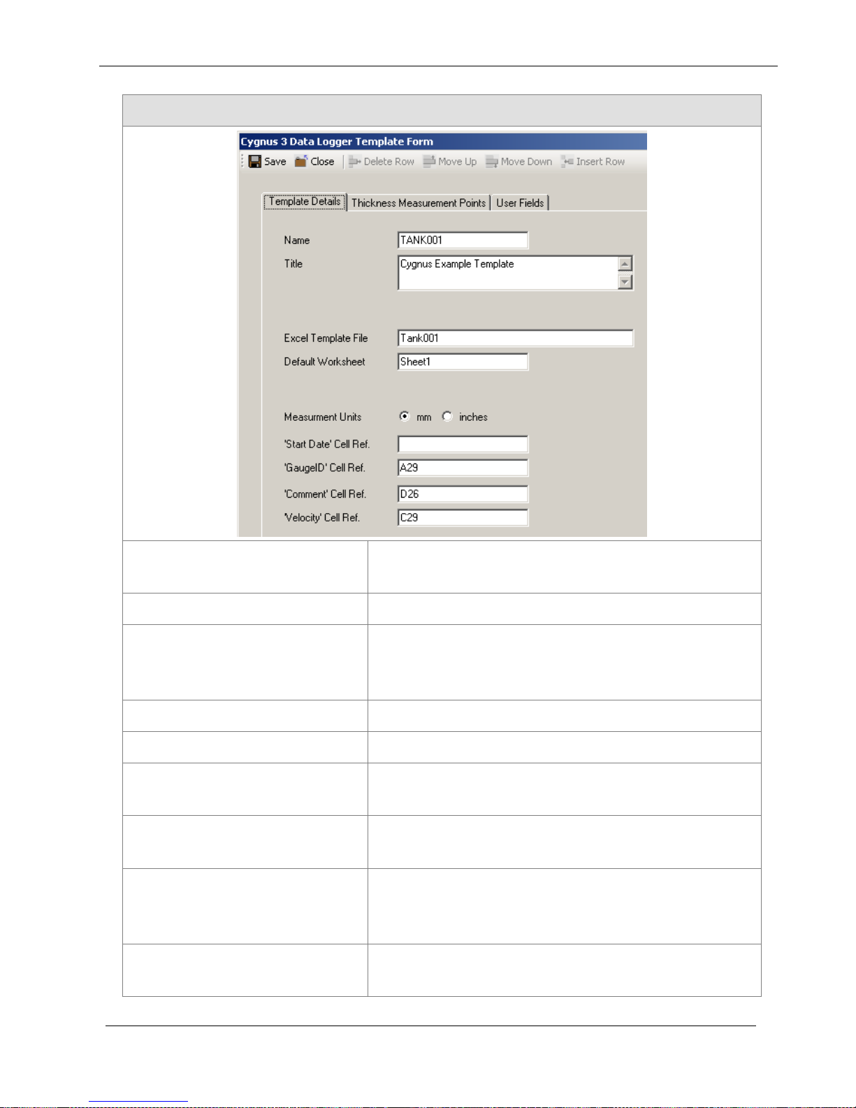
M4-CYG3-M-ENG_Iss2.doc
Cygnus 3 Operating Manual
87
Template Details Tab
Name
The name of this template file
(up to 8 characters long)
Title
A descriptive title of the template
Template File
An Excel® XLT filename that will be used
to create the final report (omit the XLT
extension)
Worksheet
The worksheet name in the XLT file
Measurement Units
The required measurement units
Start Date Cell Ref.
The Excel spreadsheet cell that the
Record Start Date must be copied into
GaugeID Cell Ref.
The Excel spreadsheet cell that the
GaugeID must be copied into
Comment Cell Ref.
The Excel spreadsheet cell that the
gauge operator’s Comment must be
copied into
Velocity Cell Ref.
The Excel spreadsheet cell that the
Velocity of Sound value must be copied
Page 88
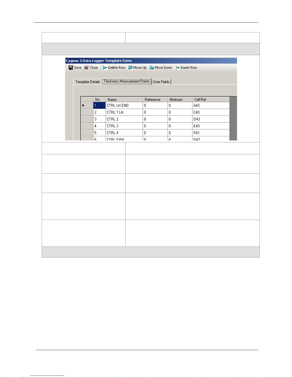
Cygnus 3 Operating Manual
M4-CYG3-M-ENG_Iss2.doc
88
into
Thickness Measurement Points Tab
No.
Measurement number, 1 to 5000
Name
The name of the measurement point (up
to 15 characters long)
Reference
The reference thickness (100% or
original thickness)
Minimum
The minimum thickness below which an
alert will be raised to the gauge
operator
Cell Ref.
The Excel® spreadsheet cell that the
measured thickness value must be
copied into
User Fields Tab
Page 89
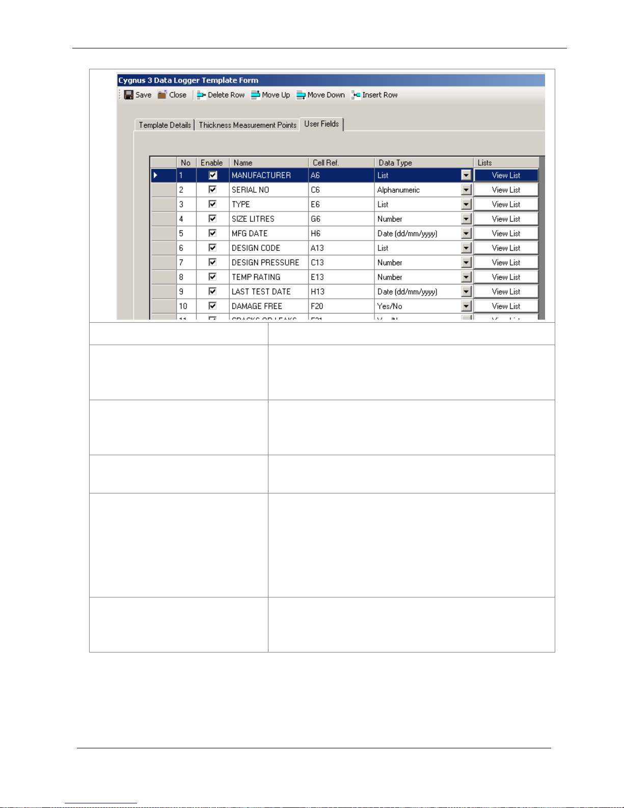
M4-CYG3-M-ENG_Iss2.doc
Cygnus 3 Operating Manual
89
No.
User Field number, 1 to 40
Enable
When ticked this field will be requested
from the gauge operator each time a
new record file is started
Name
Name of the User Field that will be
shown to the gauge operator (up to 15
characters long)
Cell Ref.
The Excel® spreadsheet cell that the
entered data must be copied into
Data Type
Choose from;
• Alphanumeric
• Number
• Date
• List
• Yes/No
Lists
When the Data Type is set to List you
can view and edit each list with this
button.
Page 90
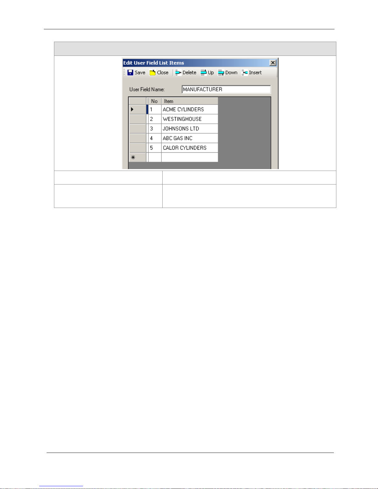
Cygnus 3 Operating Manual
M4-CYG3-M-ENG_Iss2.doc
90
User Fields List View
No.
List Item number, 1 to 40
Item
List item that will be shown to the gauge
operator (up to 15 characters long)
Once you have finished creating the Template File click the ‘Save’
button to save the data, then click the ‘Close’ button to close the
form.
Transferring Template Files to the Data Logger
To transfer template files from computer to Gauge on the Cygnus
3 Data Logger Manager menu bar click ‘Da t a Logger’ then
‘Transfer Templates to Data Logger’, the ‘Transfer
Templates to Data Logger’ dialog box will be displayed, Fig
9.12.
The drive letter should be correct, but it can be changed here
using the drop-down list.
The Template List will populate with all the template files on the
computer. Simply select the templates to transfer and then click
‘Transfer’, the selected files will be copied to the Gauge’s memory
card.
There is the option to overwrite existing template files that may
already be on the Gauge’s memory card.
Page 91
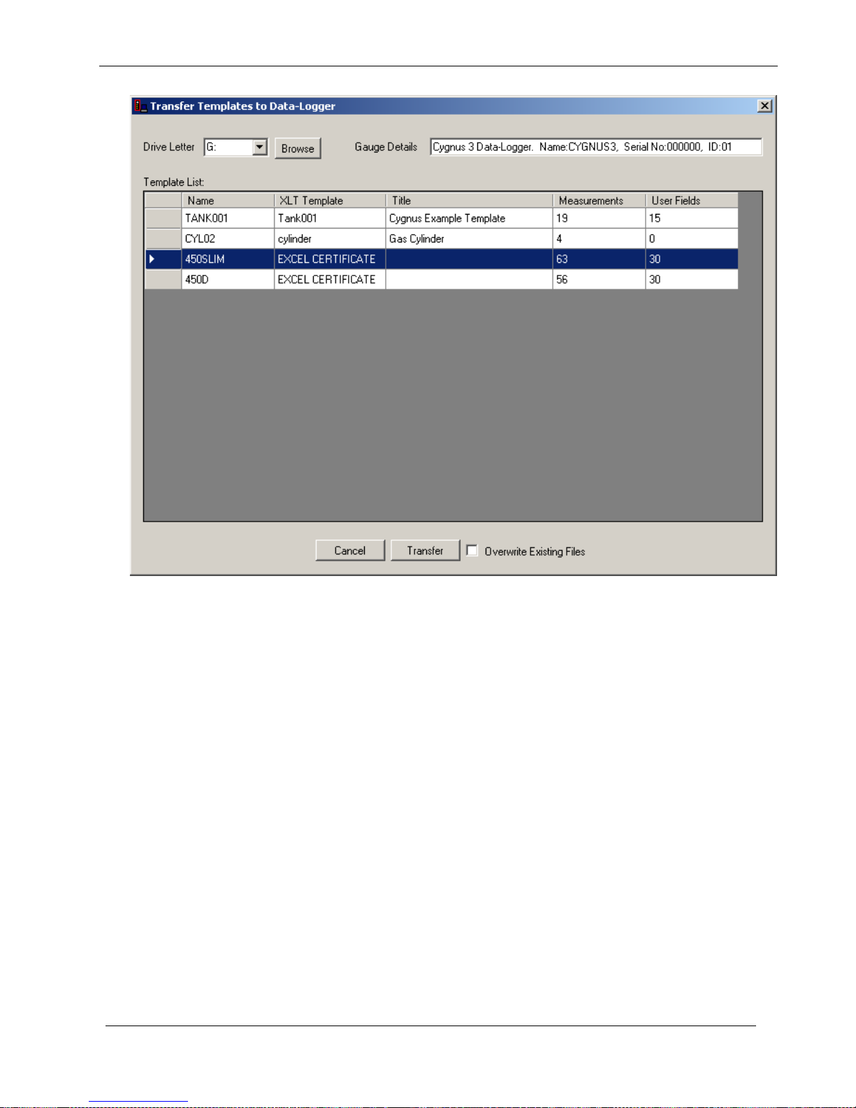
M4-CYG3-M-ENG_Iss2.doc
Cygnus 3 Operating Manual
91
Fig 9.12 Transfer Templates to Data Logger
Page 92
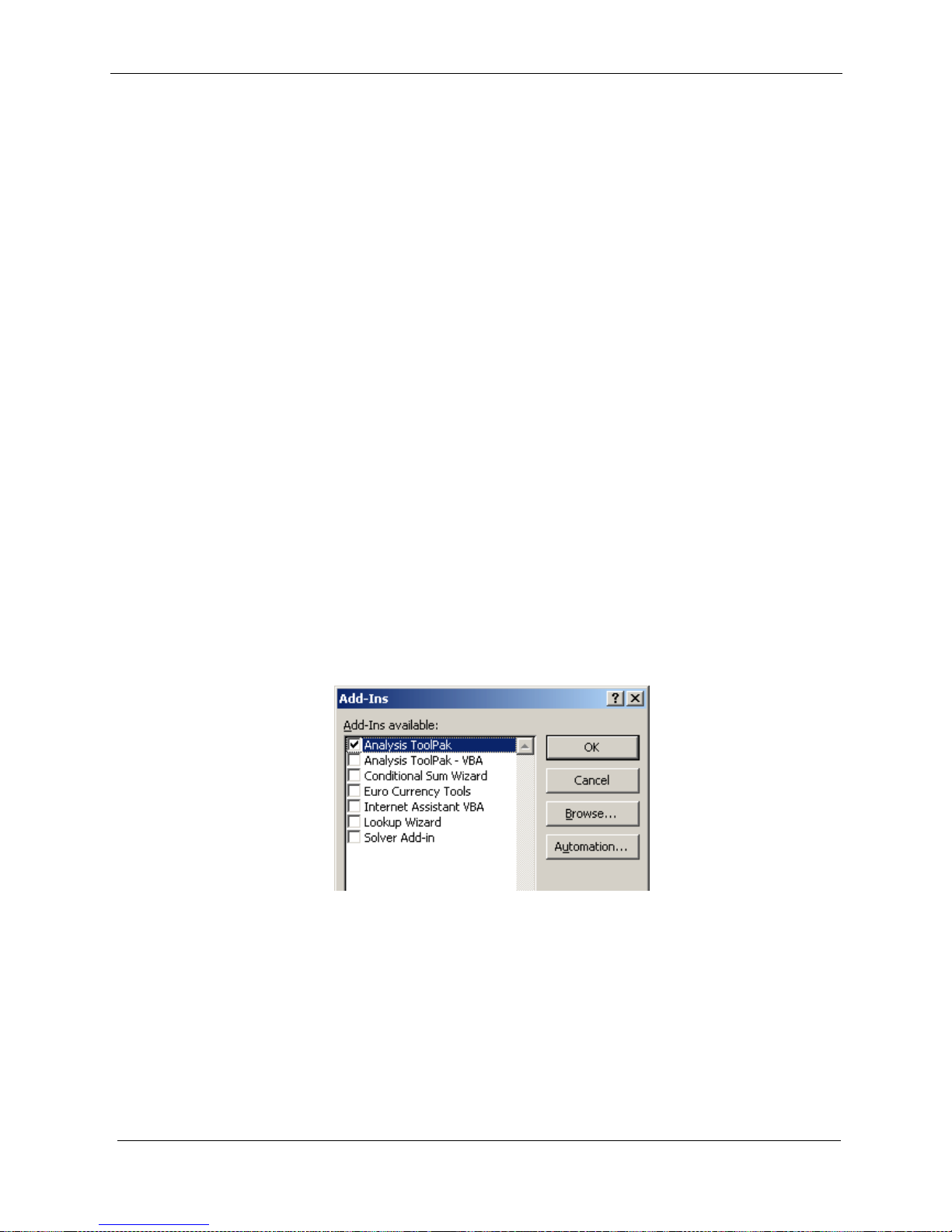
Cygnus 3 Operating Manual
M4-CYG3-M-ENG_Iss2.doc
92
10. Microsoft Excel Add-In
Overview
A Excel Add-In is provided that can automate the process of
inserting the data from a record file into a spreadsheet. The AddIn is particularly useful when using record files based on templates
as it will open the specified Excel XLT template file before inserting
the data into the specified cells.
Installing the Add-In
When the Cygnus 3 Data Logger Manager application is installed a
‘Cygnus Import Tools.xla’ file is also copied into
‘Documents\Datalogger\Add-In’ folder. This XLA file contains
the Excel Add-In code.
To install the Add-In using:
Microsoft Office Excel 2000, XP, 2003
1. Start up Excel
2. On the main menu click ‘Tools’, then ‘Add-Ins’
3. The ‘Add-Ins’ dialog box is displayed
4. Click the ‘Browse’ button
5. Browse to ‘My Documents\Datalogger\Add-In’ and select
the ‘Cygnus Import Tools.xla’ file by clicking the ‘Ok’
button.
Page 93
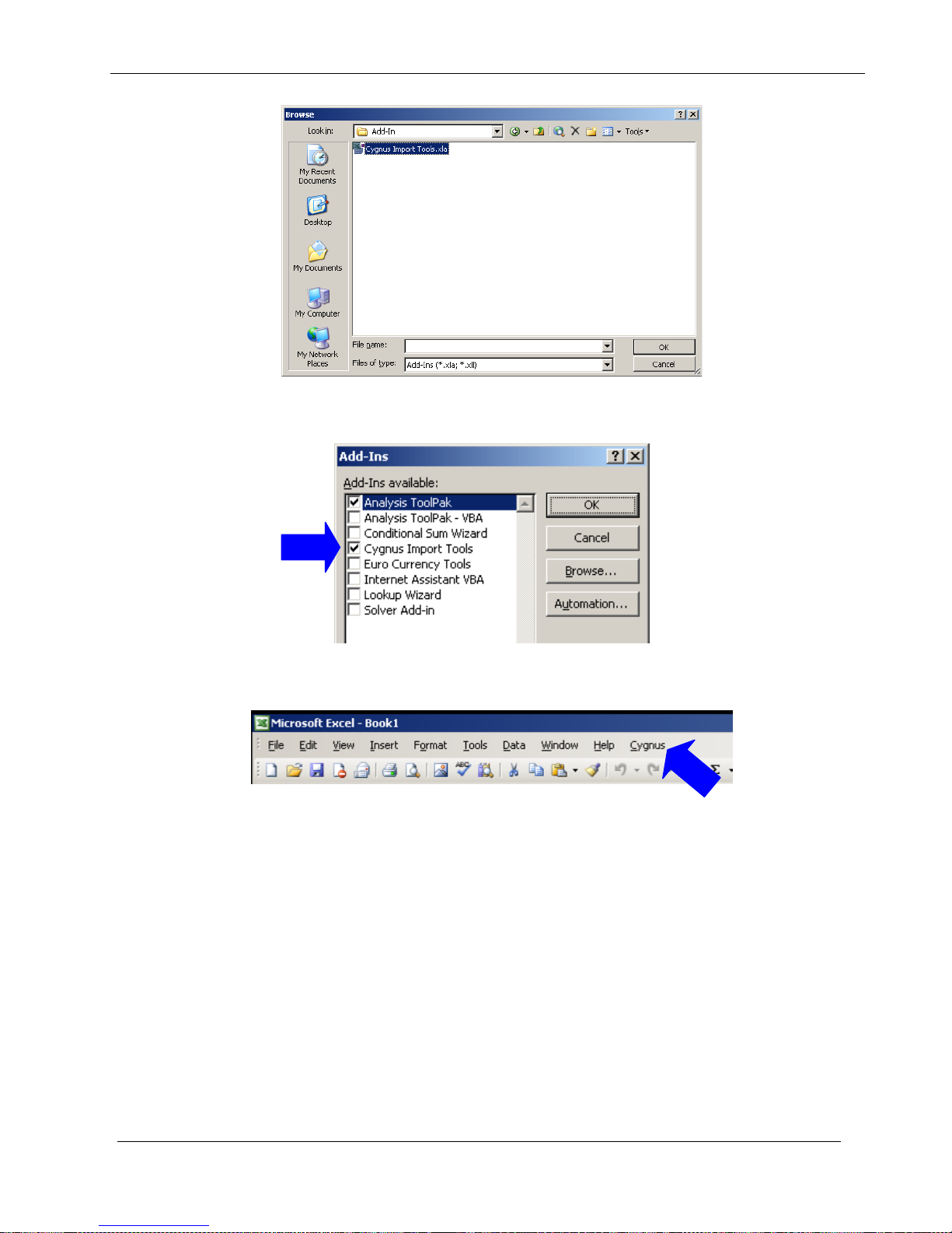
M4-CYG3-M-ENG_Iss2.doc
Cygnus 3 Operating Manual
93
6. The Cygnus Import Tools Add-In should now be listed and
ticked in the Add-Ins dialog box;
7. Click the ‘OK’ button and a new menu item ‘Cygnus’ should
be displayed in the main Excel menu on the right.
Microsoft Excel 2007
1. Start up Excel
2. Click the Microsoft Office Button, and then click ‘Excel
Options’.
3. Click the Add-Ins category. In the Manage box, click ‘Excel
Add-Ins’, and then click ‘Go’.
4. The ‘Add-Ins’ dialog box is displayed
Page 94
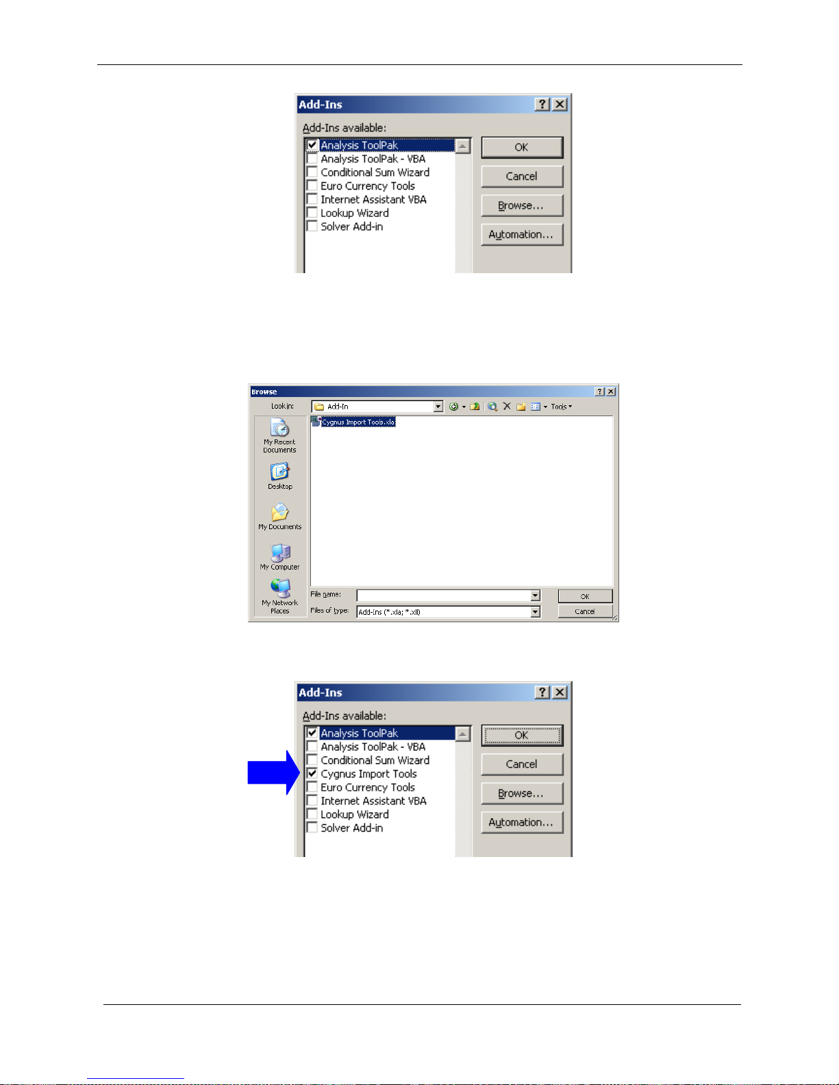
Cygnus 3 Operating Manual
M4-CYG3-M-ENG_Iss2.doc
94
5. Click the ‘Browse’ button
6. Browse to ‘My Documents\Datalogger\Add-In’ and select
the ‘Cygnus Import Tools.xla’ file by clicking the ‘Ok’
button.
7. The Cygnus Import Tools Add-In should now be listed and
ticked in the Add-Ins dialog box:
8. Click the ‘OK’ button and a new item ‘Cygnus’ should be
displayed in the Add-In ribbon commands on the left.
Page 95
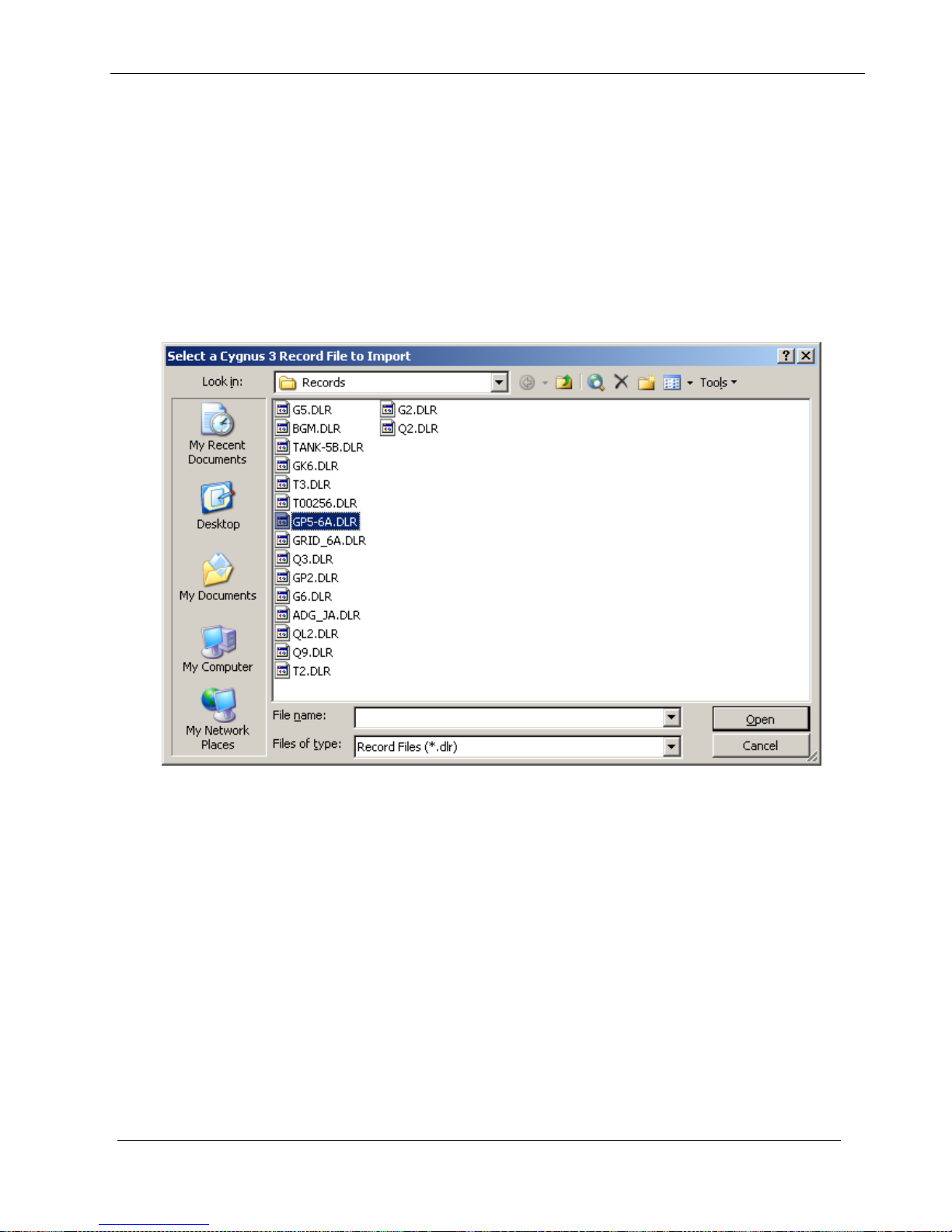
M4-CYG3-M-ENG_Iss2.doc
Cygnus 3 Operating Manual
95
Creating an Excel Report
First transfer any Record Files from the Gauge to computer using
the Cygnus 3 Data Logger Manager, see page 76.
Start by clicking on the ‘Cygnus’ item in the Excel main menu bar
(or in the Add-In ribbon for Office 2007) then the ‘Select a
Cygnus 3 Record File to Import’ dialog box will be shown as in
Fig 10.1.
Fig 10.1 Select Record File to Import
Select the required record file and click the ‘Open’ button. Another
form will be displayed that allows optional report details to be
entered that will be added to the top of the spreadsheet report,
shown in Fig 10.2.
These optional details can be included in the report by ticking the
‘Include in Report’ box.
If any of the optional fields have been changed they can be saved
for next time by ticking the ‘Save Details’ box.
To proceed and create the report click the ‘Ok’ button.
Page 96
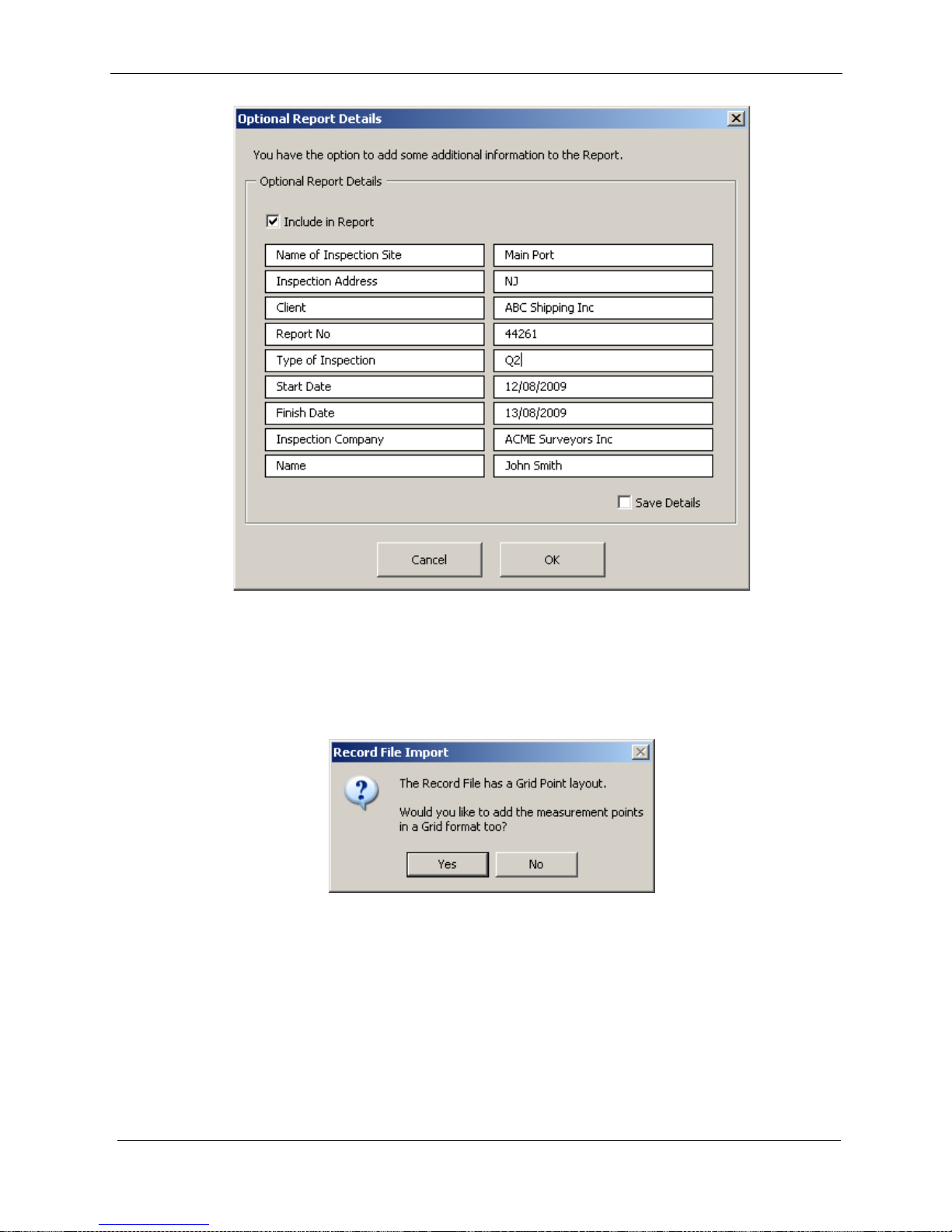
Cygnus 3 Operating Manual
M4-CYG3-M-ENG_Iss2.doc
96
Fig 10.2 Optional Report Details
If the Record File has a Grid Point layout a dialog box will ask if
the thickness measurement values should be arranged in a grid
layout – select ‘Yes’ or ‘No’ as required, shown in Fig 10 . 3.
Fig 10.3 Grid Layout Option
The data from the selected record file is now inserted into a new
Excel
®
worksheet. Fig 10.4 shows an example Grid Point record
file that also contains additional radial points.
Page 97
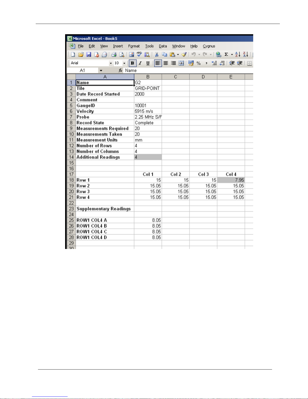
M4-CYG3-M-ENG_Iss2.doc
Cygnus 3 Operating Manual
97
Fig 10.4 Grid Point Layout Example in Excel
Additional Measurements
Any measurement points that have Addit iona l M e asu rements have
a grey background, the additional measurements are then listed
below, shown in Fig 10.5.
For more information on Additional Measurements see page 64.
Page 98
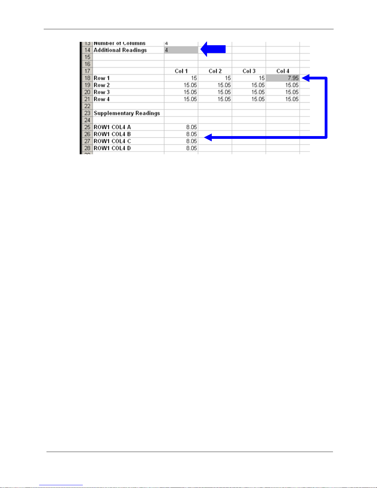
Cygnus 3 Operating Manual
M4-CYG3-M-ENG_Iss2.doc
98
Fig 10.5 Additional Measurements.
Page 99
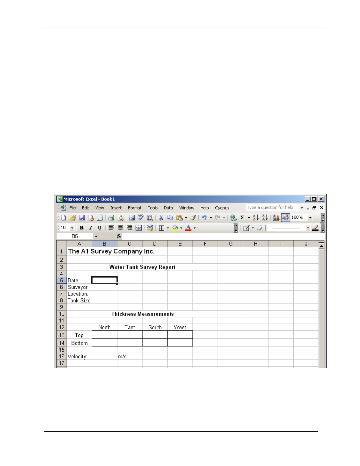
M4-CYG3-M-ENG_Iss2.doc
Cygnus 3 Operating Manual
99
11. Data Logging Template Tutorial
This tutorial goes through the steps required to create a new
Template that will ultimately populate an Excel
®
spreadsheet with
thickness measurements and user field data that has been logged
on the Cygnus 3 gauge. This will introduce the concepts behind
the template system so you can go on to create y our ow n
templates.
Create the Excel® Spreadsheet
Consider we are a surveying company and have an Excel®
spreadsheet where we need to record 8 thickness measurement
values for a water tank along with additional information for: date
of survey, name of surveyor, location of tank and the tank size.
The spreadsheet could look like fig. 11.1.
Fig. 11.1. The Exce
®
Spreadsheet.
This spreadsheet has been saved as an Excel
®
Template (.XLT) file
as shown in fig. 11.2. Note “Save as type” is set to Template
(*.xlt).
Page 100
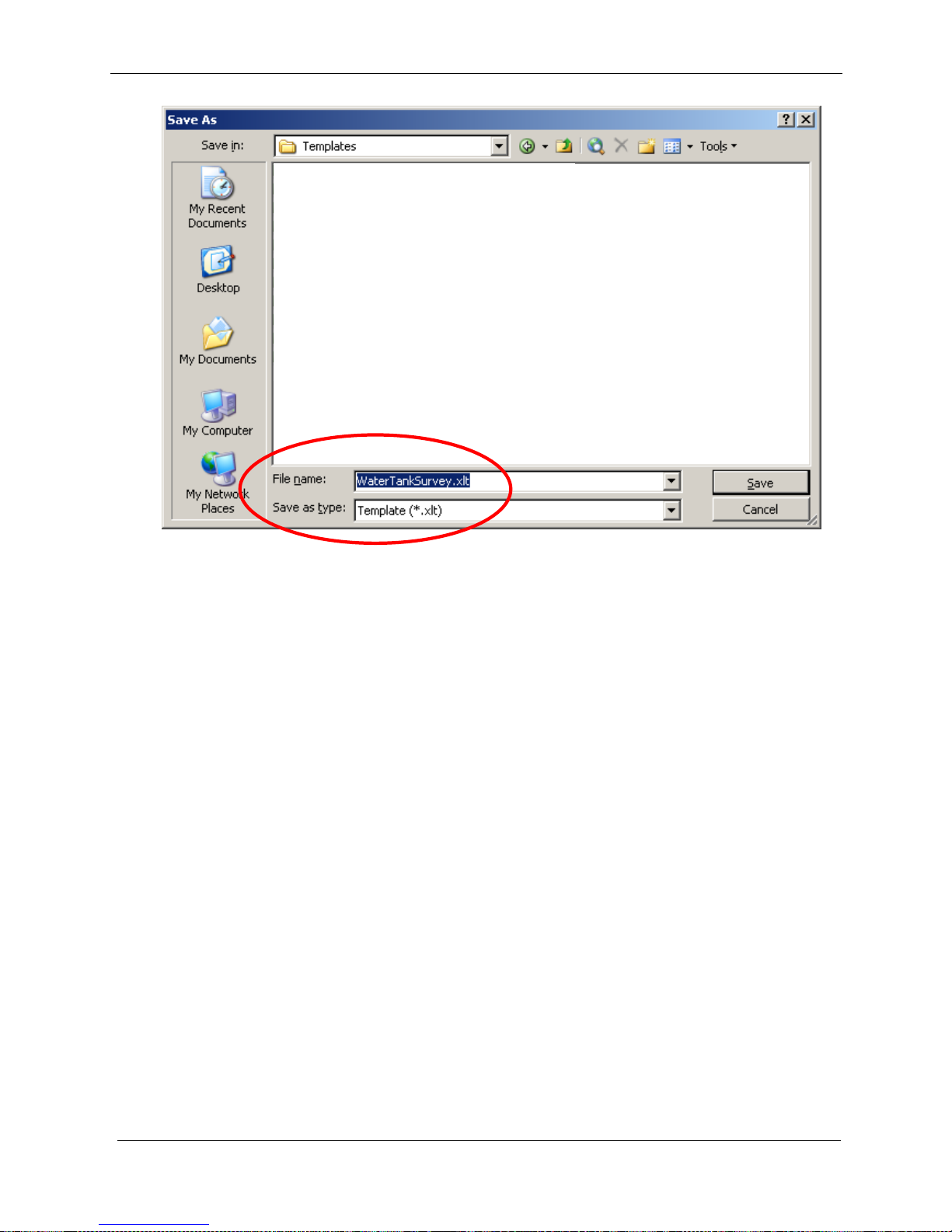
Cygnus 3 Operating Manual
M4-CYG3-M-ENG_Iss2.doc
100
Fig. 11.2. Saving the Excel
®
Spreadsheet as XLT
We will need to keep a copy of this spreadsheet handy for when
we create the Data Logger Template, we will need to identify the
cell locations where we want the thickness measurement values
and other information to go, fig. 11.3. shows these cells
highlighted.
 Loading...