

Page 1
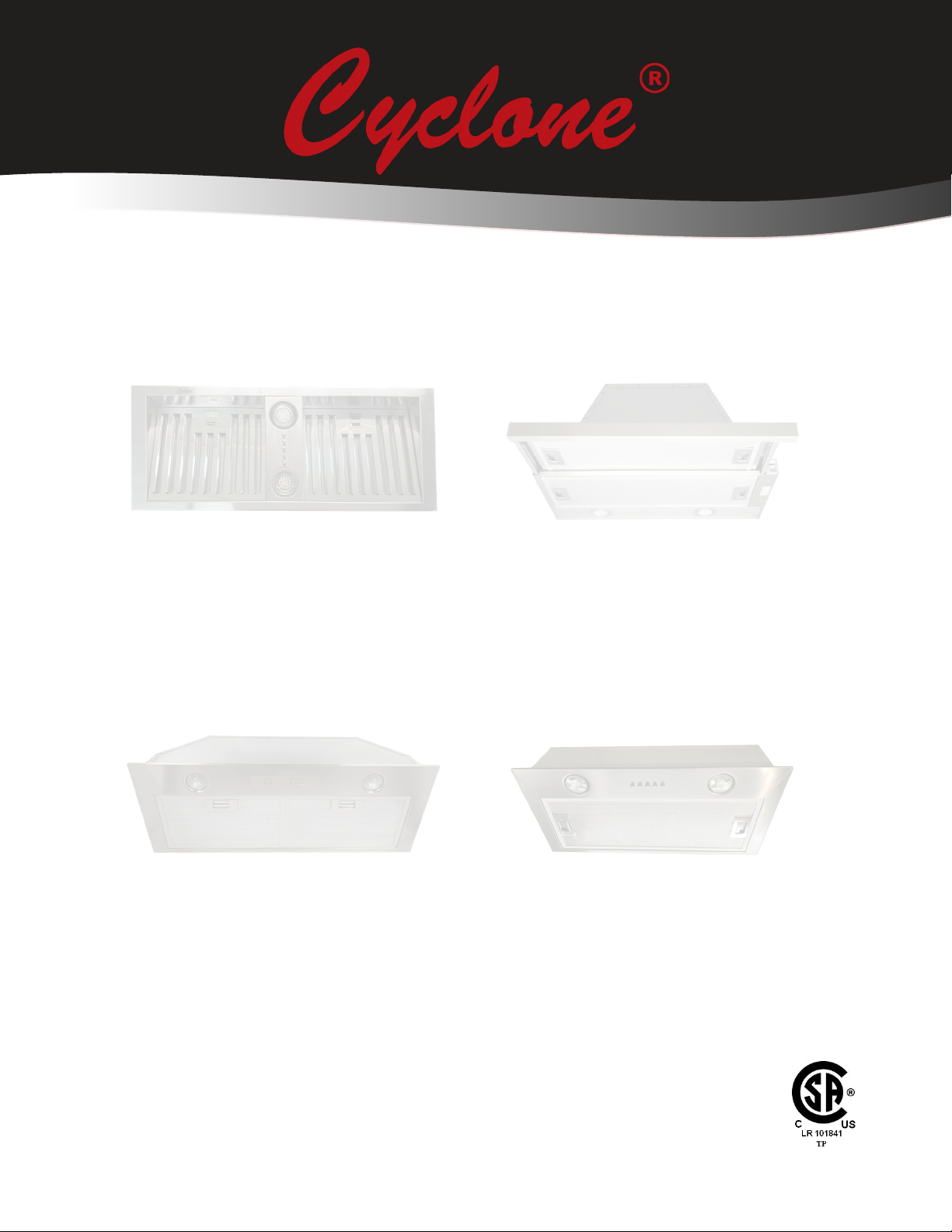
Self-Cleaning Range HoodsSelf-Cleaning Range Hoods
Insert Range Hoods
Models:
BX212, BX215, BX155, BX600, BX360 CLX60, SS130
Installation and Operation Instructions
Please read all instructions before installing and operating.
All wiring and installation must be in accordance with CEC, NEC and local electrical codes.
READ AND SAVE THESE INSTRUCTIONS
Page 2
IMPORTANT SAFETY INSTRUCTIONS
WARNING
• is appliance must be installed by a qualied technician.
• e manufacturer declines all responsibilities in the event of
failure to observe the instructions given here for installation,
maintenance and suitable use of the product.
• e manufacturer further declines all responsibility for injury
due to negligence, and the warranty of the unit automatically
expires due to improper installation and maintenance.
CAUTION
• Suitable for use in household cooking area.
• For residential cooking use only. Do not use to exhaust
hazardous or explosive materials or vapors.
• Two installers are recommended because of the size and
weight of this hood.
• Do not use more than 20 watts per halogen lightbulb for
this model.
• Light bulbs combined are not to exceed 40 watts.
• Use LED bulb, 1.5W Maximum per bulb, for SS130.
• *Bulb & socket may change.
• Mesh lters may discolour over time. Although product is
dishwasher friendly, depending on the amount of grease
and the type of dish-washing solutions used it may cause
the mesh lters to discolour faster.
WARNING
TO REDUCE THE RISK OF RANGE TOP GREASE FIRE:
WARNING
TO REDUCE THE RISK OF FIRE, ELECTRIC SHOCK, OR
INJURY TO PERSONS, OBSERVE THE FOLLOWING:
1. Use this unit only in the manner intended by the manufacturer.
2. Before servicing or cleaning the unit, switch power o
at service panel and lock service panel to prevent power
from being switched on accidentally. When the service
disconnecting means cannot be locked, securely fasten a
prominent warning device to the service panel.
3. Installation work and electrical wiring must be done by
qualied persons in accordance with all applicable codes
and standards, including re-rated construction.
4. Sucient air is needed for proper combustion and exhausting
of gases through the ue of fuel burning equipment to
prevent back draing. Follow the heating equipment
manufacturer’s guideline and safety standards as published
by the local code authorities.
5. When cutting or drilling into walls or ceilings, be careful
not to damage existing electrical wiring and other hidden
utilities.
6. To reduce the risk of re, electric shock and to properly
exhaust air, ducted fans must always be vented outdoors.
Do not vent exhaust air into spaces within walls, ceilings,
attics, crawl spaces, or garages. Do not connect this fan
with any solid-state speed control device.
7. Always keep the duct clear to maintain proper airow for
venting.
8. e bottom of the hood MUST NOT BE LESS than 28”
and at a suggested maximum of 36” above cooktop for
best capture of cooking impurities. For a gas range, the
bottom of the hood MUST NOT BE LESS than 30” above
cooktop.
2 Cyclone Insert Installation - English
1. Never leave the range unattended at high settings.
2. Always turn hood ON when cooking at high heat or when
aming food.
3. Use proper pan size. Always use cookware appropriate for
the size of the surface element.
4. Keep fan, lters and grease laden surfaces clean. Clean
ventilating fans frequently. Do not allow grease to
accumulate on fan or lter.
5. Use HIGH setting on hood only when necessary.
6. Don’t leave hood unattended when cooking.
7. To reduce the risk of re, use only metal ductwork.
8. is unit must be grounded.
9. Not for outdoor use.
WARNING
• Do not repair or replace any part of this appliance unless
specically recommended in this book. All other service
should be performed by a qualied technician.
• e hood motor has a thermal overload that will
automatically shut o the motor if it becomes overheated.
e motor will restart. If the motor continually shuts o
and restarts, contact the Cyclone service department.
Ensure that the hood is mounted at the recommended
mounting height.
• is product may have sharp edges. Be careful to avoid
cuts and abrasions during installation and cleaning.
3Cyclone Insert Installation - English
Page 3
CONTENTS
Important Safety Instructions 3
Damage Inspection 5
DAMAGE INSPECTION
• Please fully inspect unit for damage before installation.
• If the unit is damaged in shipment, return the unit to the store in which it was bought for repair or replacement.
• If the unit is damaged by the customer, repair or replacement is the responsibility of the customer.
• If the unit is damaged by the installer (if other than the customer), repair of replacement must be made by arrangement between
customer and installer.
• Once installed, all damages will be assumed the responsibility of the installer.
Ducting 5
Mounting Heights and Clearance 6
Wiring Installation 6
Tools and Materials Required 7
SS130 Installation - Parts supplied 8
SS130 Insert Hood Installation 9
SS130 Installation - Installation Cutout Templates 10
BX155/BX212/BX215 Installation - Parts supplied 11
BX212/BX215 Insert Hood Installation 12
BX155 Insert Hood Installation 13
BX155/BX212/BX215 Installation - Installation Cutout Templates 14
BX600/BX360/CLX60 Installation - Parts supplied 15
BX600/BX360/CLX60 Insert Hood Installation 16
BX600/BX360/CLX60 Installation - Installation Cutout Templates 17
Insert Hoods Specications 18
Troubleshooting 19
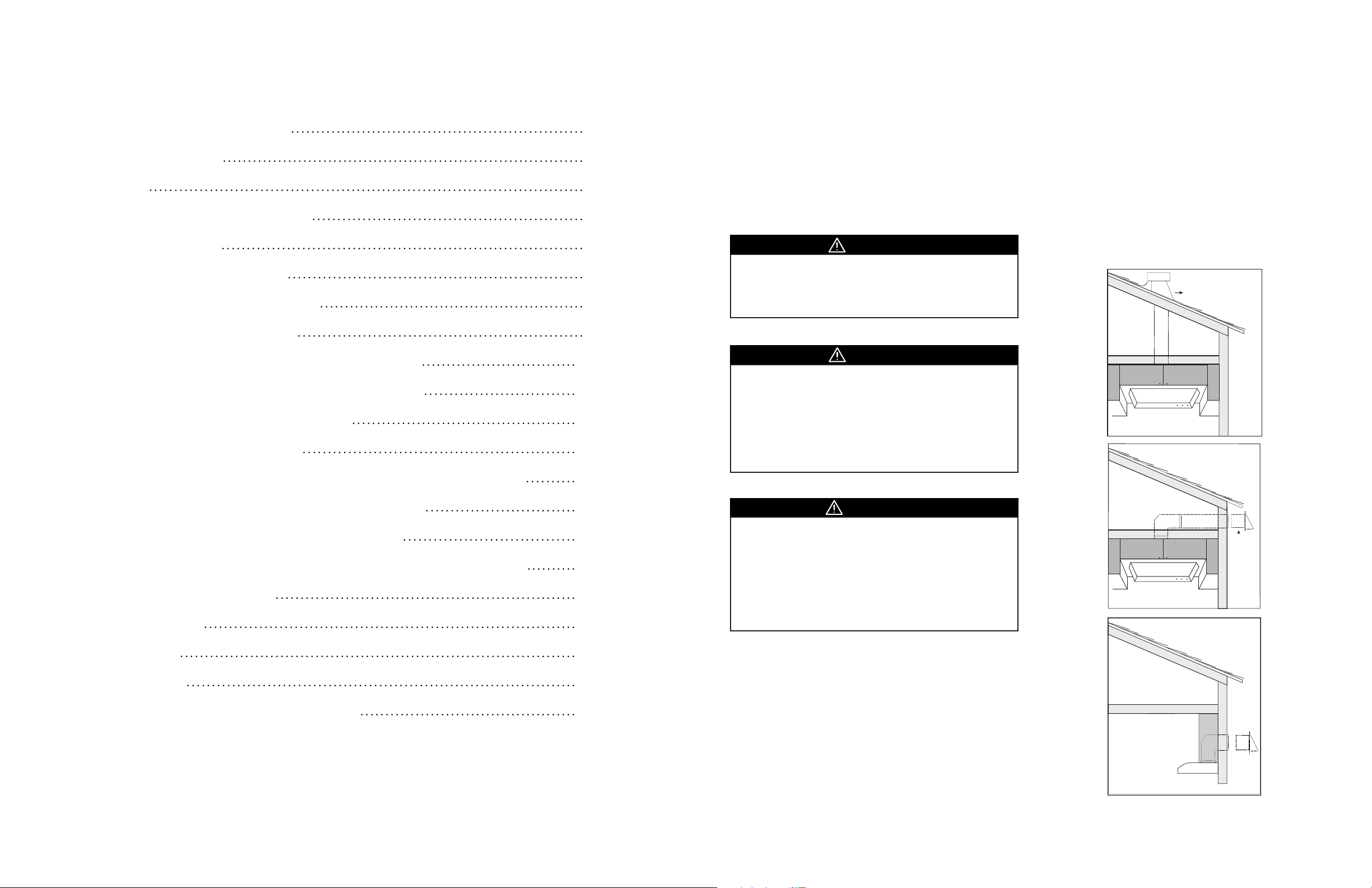
DUCTING
WARNING
• To reduce the risk of re, use only metal ductwork.
• To reduce risk of re and to properly exhaust air, be sure
to duct air outside – do not vent exhaust air into spaces
within walls, ceilings, attics, crawl spaces, or garages.
CAUTION
• Best to use rigid type metal ducts. Flexible ducts can
restrict airow by more than 50%.
• Reduce the number of transitions and turns as much as
possible. If a reducer is used, install a long reducer instead
of a pancake reducer. If turns and transitions are required,
install them as far away from the opening as possible and
as far apart between two as possible.
WARNING
• 6” round ductwork must be used to maintain maximum
air ow eciency with motors of 450 CFM or greater. If
the use of any size ducting is less than 6”, the warranty is
automatically voided.
• e venting duct must go horizontally or vertically up
to the outside wall or the roof. If it is turned downward
anywhere in the venting system, the warranty is automatica lly
voided.
Examples of dierent types of ventilation for
inserts:
Roof Pitch with Cap
and Flashing
Soffit or Crawl Space
Side Wall Cap
with Gravity
Damper
Maintenance 20
Control Panel 21
Cyclone Range Hoods Limited Warranty 22
4 Cyclone Insert Installation - English
Fasten all connections with sheet metal screws and tape all joints
with certied silver tape or duct.
Do not cut a joist or stud unless absolutely necessary. If a joist or
stud must be cut then a supporting frame must be constructed.
Before making cutouts make sure there is proper clearance within
the ceiling or wall for the exhaust vent.
Additional parts not provided.
Side Wall Cap with
Gravity Damper
5Cyclone Insert Installation - English
Page 4
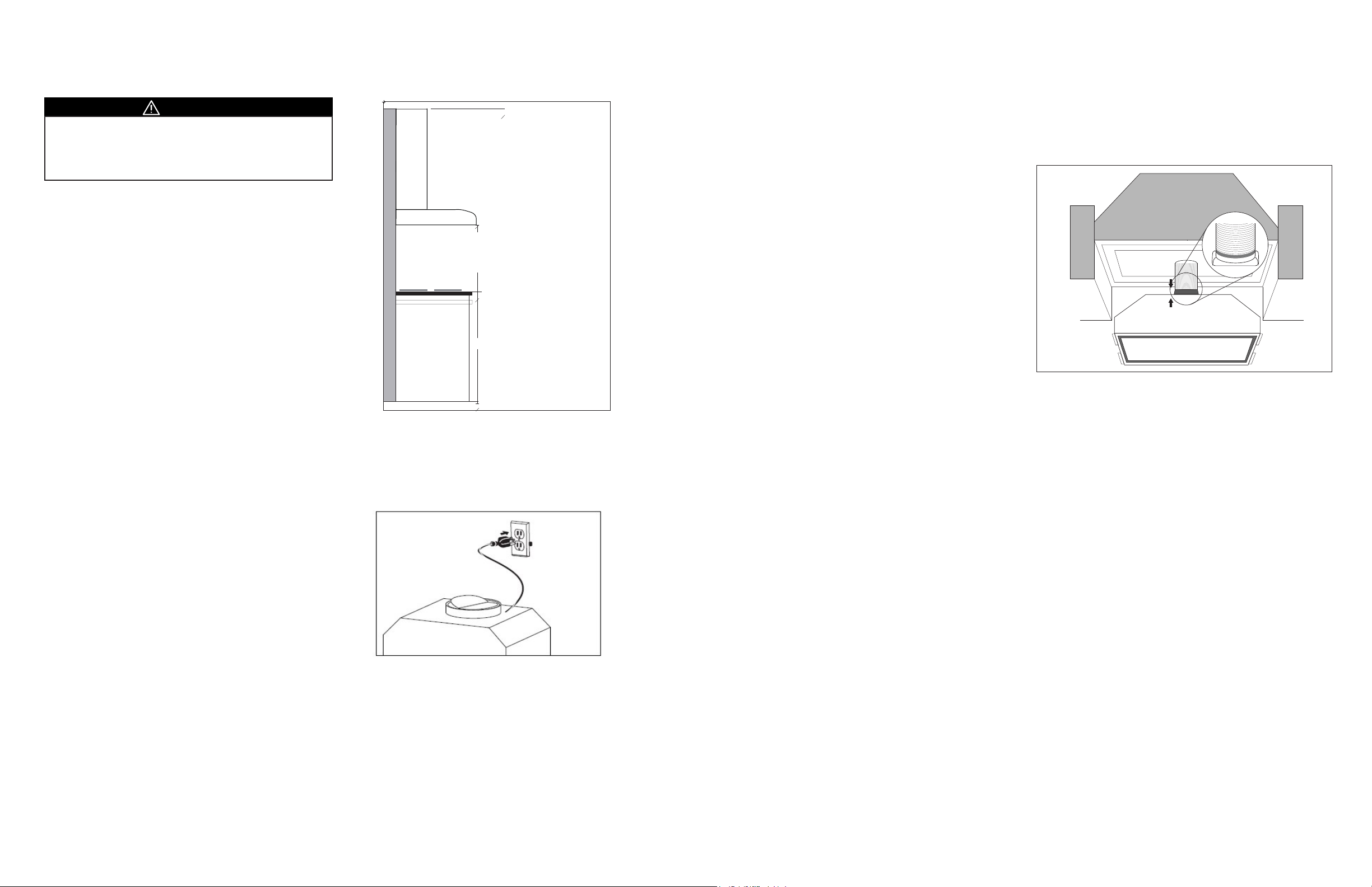
MOUNTING HEIGHTS AND CLEARANCE
Preparation for Vent and Exhaust Duct Connection
Ducting Connection
WARNING
• e hood should be installed at 28” minimum above the
cooking surface. If pairing your range hood with a gas
stove minimum mounting height must be 30” above the
cooking surface.
Minimum mount height between range top to hood bottom should
be no less than 28” for electric or ceramic stoves, and no less than 30”
for gas stoves. e maximum mount height should be no more than
36”. e hood must be installed at the correct mounting height. Hoods
mounted too low could result in heat damage. Hoods mounted too
high, on the other hand, will be less eective and performance may
suer.
Check your ceiling height and the hood height maximum before
you select your hood.
Hood installation height above cook top is the user’s preference.
e lower the hood is above the cook top the more ecient it will
be in drawing out cooking odors, grease and smoke.
Max:
Max:
Min:
Gas
Gas 30”
Ceramic/Electric
Ceramic/Electric
Min:
36”
36”
30”
36”
28”
28”
1. To connect a rectangular vent to a round exhaust duct (or vice
versa), use a connecting duct and adapter.
2. e round vent of a Cyclone Range Hood is 6” diameter. If
the round exhaust duct is not 6” diameter, a connecting duct
is necessary to accommodate the dierent size. If the exhaust
duct is less than 6” diameter, the eciency of your Cyclone
Range Hood will be reduced and the warranty may be voided.
3. An exhaust duct needs to be cut if there is not an existing duct
in your home. Please consult/hire a professional to complete
the work properly. For top venting, a rectangular or a 6”
round hole needs to be cut through the ceiling or the back
wall and the bottom of the cabinet to t the duct connection.
When there is no access to the top of the hood, carefully pull down
the metal duct through the custom hood base hole. Slide this duct
over the adapter/damper. Make sure the adapter/damper assembly
enters the ducting. Seal the connection with aluminum tape.
WIRING INSTALLATION
is appliance requires 120V 60Hz electrical supply and connection to an individual properly grounded branch circuit protected
by a circuit breaker or time delay fuse.
Install the Electrical Power Supply
Install a junction box inside the upper corner of the cabinet. For
the model SS13024, it should be installed at a minimum of 8” away
from the center of the cabinet and 12” above the bottom of the
cabinet. For the models SS13030, BX21228/BX21528, BX600/
CLX60, it should be installed at a minimum of 11” away from the
center of the cabinet, and 12” above the bottom of the cabinet. For
the model BX21234/BX21534, it should be installed at a minimum
of 13” away from the center of the cabinet, and 12” above the
bottom of the cabinet.
TOOLS AND MATERIALS REQUIRED
• Electrical drill or ratchet driver
• Phillips screwdriver #2 or driver bit
• Straight blade screwdriver
• Wire stripper or cutter
• Tape measure
• Electrical supplies for wiring (i.e. wire connectors,
electrical tape)
• Aluminum foil tape and/or duct tape
• Hammer
• Jigsaw or saber saw
• Step ladder
• Pencil
6 Cyclone Insert Installation - English
7Cyclone Insert Installation - English
Page 5
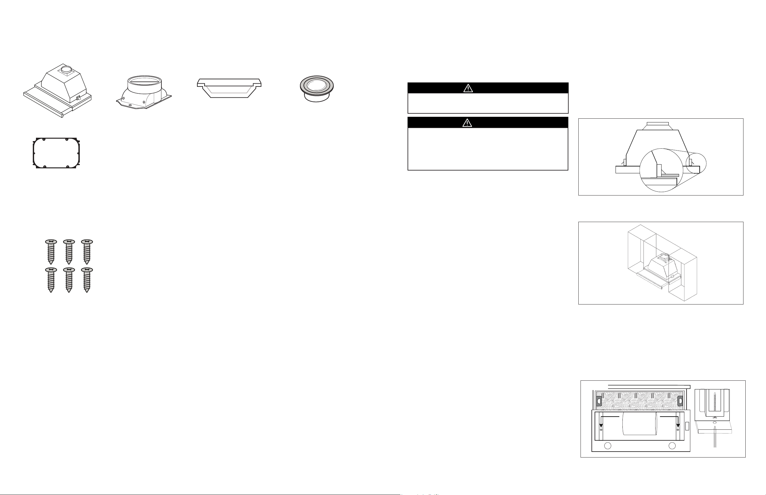
SS130 INSTALLATION - PARTS SUPPLIED
SS130 INSERT HOOD INSTALLATION
1 × Hood
1 × Plastic Adapter Seal
6 × Adapter Screws
1 × Round Adapter
1 × Rectangular Oil Collector
HARDWARE PACKAGE
PRE-INSTALLED
2 × LED Lights
(1.5W per bulb)
*Bulb & socket may change.
is appliance requires 120V 60Hz electrical supply and
connection to an individual properly grounded branch circuit
protected by a circuit breaker or time delay fuse.
CAUTION
• At least two installers are required due to the weight and
size of the hood.
WARNING
• Turn o power circuit at the service panel before wiring
this unit.
• All electrical work must be done by a qualied electrician
in accordance with all applicable codes and standards.
is range hood must be properly grounded.
Preparation for Installation
1. Unpack range hood and check contents. Note: Be cautious of
sharp edges within the unit.
2. Cut the insert cutout at the bottom of the cabinet using the
given cutout measurements on page 10 (Figure 1).
3. Locate the cutout at the center of the bottom of the cabinet.
Ensure that the front panel of the range hood is ush with the
surface of the cabinet doors.
Install the SS130 Range Hood
1. Remove outer mesh lters of range hood
2. Attach damper to rectangular cutout on top of the range
hood using the screws provided.
3. Hold range hood upright, mesh lters facing down and
insert range hood upward into cabinet cutout. e range
hood mounts to the cabinetry by two spring loaded brackets,
one on each side of the range hood (Figure 2).
Figure 2.
4. Once the range hood is through the cabinetry the brackets
should release. e brackets loosely hold the range hood in
place (Figure 3).
Figure 3.
8 Cyclone Insert Installation - English
5. Pull the slide outwards to expose the inside of the range
hood. Locate the adjustable screw hole underneath both
sides of the hood.
6. Once located, use a Phillips screwdriver to tighten the
adjustable screw until the unit is tightly fastened to the base
of the cabinetry (Figure 4).
7. Make sure that the adapter is connected to ductwork.
8. Place mesh lters back into place.
9. Connect the power plug to the junction box.
Figure 4.
Fasten Screws
9Cyclone Insert Installation - English
Page 6
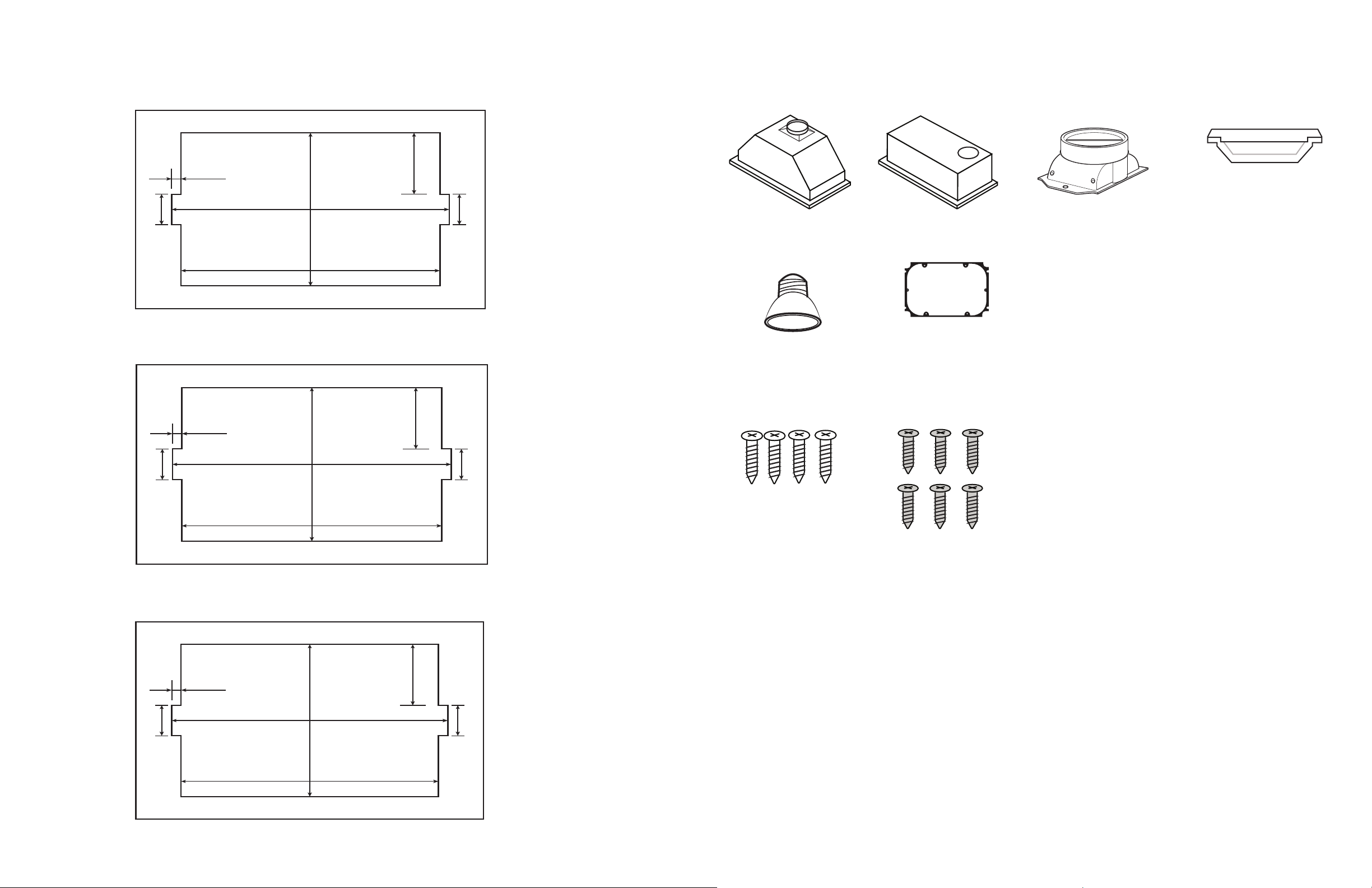
SS130 INSTALLATION - INSTALLATION CUTOUT TEMPLATES
19 ⅜”
17 ⅞”
¾”
Classic Collection Insert - Model: SS13024
Cut Out
10 ¼”
2”
2”
4 ⅛”
25 ⅜”
23 ⅞”
¾”
Classic Collection Insert - Model: SS13030
Cut Out
10 ¼”
4 ⅛”
2”2”
31 ¼”
29 ¾”
¾”
Classic Collection Insert - Model: SS13036
Cut Out
10 ¼”
4 ⅛”
2”2”
BX155/BX212/BX215 INSTALLATION - PARTS SUPPLIED
SS13024
SS13030
1 × Hood BX212/BX212
INCLUDED IN UNIT
2 × Halogen Lights
(120V, 20W per bulb)
4 × Mounting Screws
1 × Hood BX155
1 × Plastic Adapter Seal
(BX212/BX215 only)
1 × Round Adapter
(BX212/BX215 only)
HARDWARE PACKAGE
6 × Adapter Screws
(BX212/BX215 only)
1 × Rectangular Oil Collector
SS13036
10 Cyclone Insert Installation - English
11Cyclone Insert Installation - English
Page 7
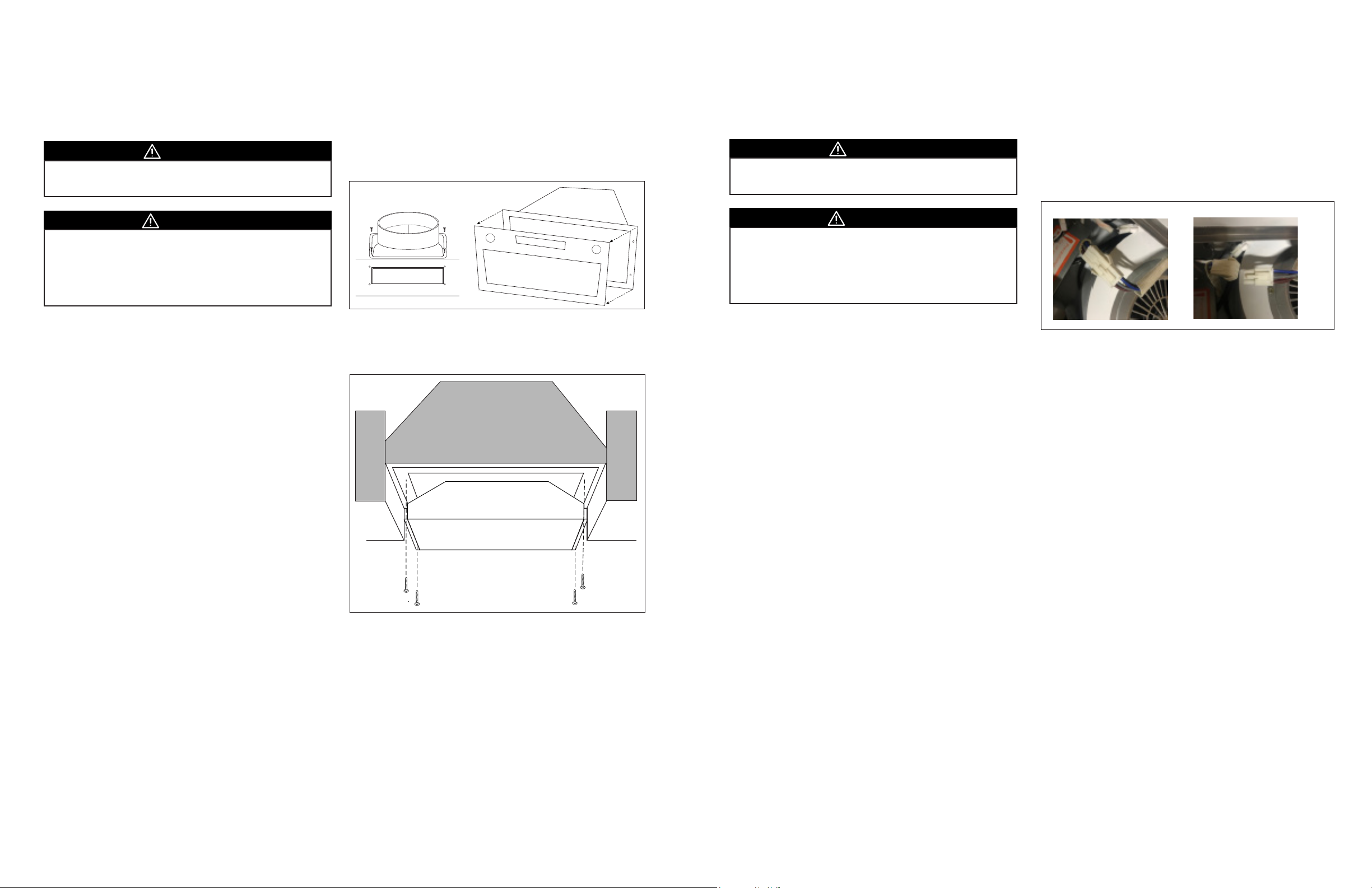
BX212/BX215 INSERT HOOD INSTALLATION
BX155 INSERT HOOD INSTALLATION
is appliance requires 120V 60Hz electrical supply and
connection to an individual properly grounded branch circuit
protected by a circuit breaker or time delay fuse.
CAUTION
• At least two installers are required due to the weight and
size of the hood.
WARNING
• Turn o power circuit at the service panel before wiring
this unit.
• All electrical work must be done by a qualied electrician
in accordance with all applicable codes and standards.
is range hood must be properly grounded.
Prepare for Installation
1. Unpack range hood and check contents. Note: Be cautious of
sharp edges within the unit.
2. Cut the insert cutout at the bottom of the cabinet using the
given cutout measurements on page 14.
3. Locate the cutout at the center of the bottom of the cabinet.
Installing the BX212/BX215 Range Hood
1. Remove outer mesh lters of range hood.
2. Attach damper to rectangular cutout on top of the range
hood using the screws provided (Figure 2).
3. Remove the mesh lters, locate the four Phillips screws.
Figure 3.Figure 2.
Top Panel
ere are 2 on the right side and 2 on the le side. Remove
the 4 screws using your screwdriver or power drill and place
them aside as you will need them later on to reattach the
face. Remove the face and set it aside (Figure 3).
Figure 4.
is appliance requires 120V 60Hz electrical supply and
connection to an individual properly grounded branch circuit
protected by a circuit breaker or time delay fuse.
CAUTION
• At least two installers are required due to the weight and
size of the hood.
WARNING
• Turn o power circuit at the service panel before wiring
this unit.
• All electrical work must be done by a qualied electrician
in accordance with all applicable codes and standards.
is range hood must be properly grounded.
Prepare for Installation
1. Unpack range hood and check contents. Note: Be cautious of
sharp edges within the unit.
2. Cut the insert cutout at the bottom of the cabinet using the
given cutout measurements on page 14.
3. Locate the cutout at the center of the bottom of the cabinet.
Installing the BX155 Range Hood
Once the cutout has been made to the insert:
1. Place range hood on its side where the control panel and light
bulbs are on the bottom, closest to the table.
2. Remove mesh lter from range hood and locate 3 quick release
wire connectors inside the cavity of the hood. ere are 2 for
the lights and 1 for the switch/controls. Gently squeeze the
plastic tabs and pull apart the connectors. (Figure 1)
Figure 1.
3. Once all 3 wires have been disconnected, locate the four
Phillips screws. ere are 2 on the right side and 2 on the le
side. Remove the 4 screws using your screwdriver or power
drill and place them aside as you will need them later on to
reattach the face. Remove the face and set it aside.
4. With the face removed, you will expose 4 holes in the body of
the hood. 2 on the right side and 2 on the le side. Insert the
hood into the cavity of the cabinet and secure it by driving the
screws through the pilot holes and directly into the bottom of
the cabinet.
5. With the hood secured to the cabinet, you can now reinstall
the face and reconnect all the wires.
12 Cyclone Insert Installation - English
4. Hold range hood upright, and insert range hood upward
into cabinet cutout. Secure the range hood to the cabinet
using the four screws provided. Two for each side (Figure 4).
5. Reattach and screw top panel onto range hood.
6. Make sure that the adapter is connected to ductwork.
7. Place mesh lters back into place.
8. Connect the power plug to the junction box.
13Cyclone Insert Installation - English
Page 8
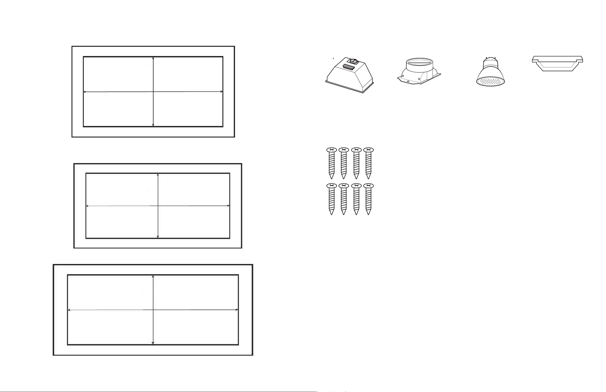
10 ⅝”
26 ½”
Classic Collection Insert - Model: BX21528
Cut Out
13 ½”
32”
Classic Collection Insert - Model: BX21534
Cut Out
BX155/BX212/BX215 INSTALLATION - INSTALLATION CUTOUT TEMPLATES
20 ⅝”
10 ⅜”
Classic Collection Insert - Model: BX15522
Cut Out
BX15522
BX21228/BX21528
BX600/CLX60 INSTALLATION - PARTS SUPPLIED
1 × Hood
8 × Mounting Screws
PRE-INSTALLED
1 × Round Adapter
PRE-INSTALLED
2 × LED Lights
(1.5W per bulb)
HARDWARE PACKAGE
1 × Rectangular Oil Collector
BX21234/BX21534
14 Cyclone Insert Installation - English
15Cyclone Insert Installation - English
Page 9
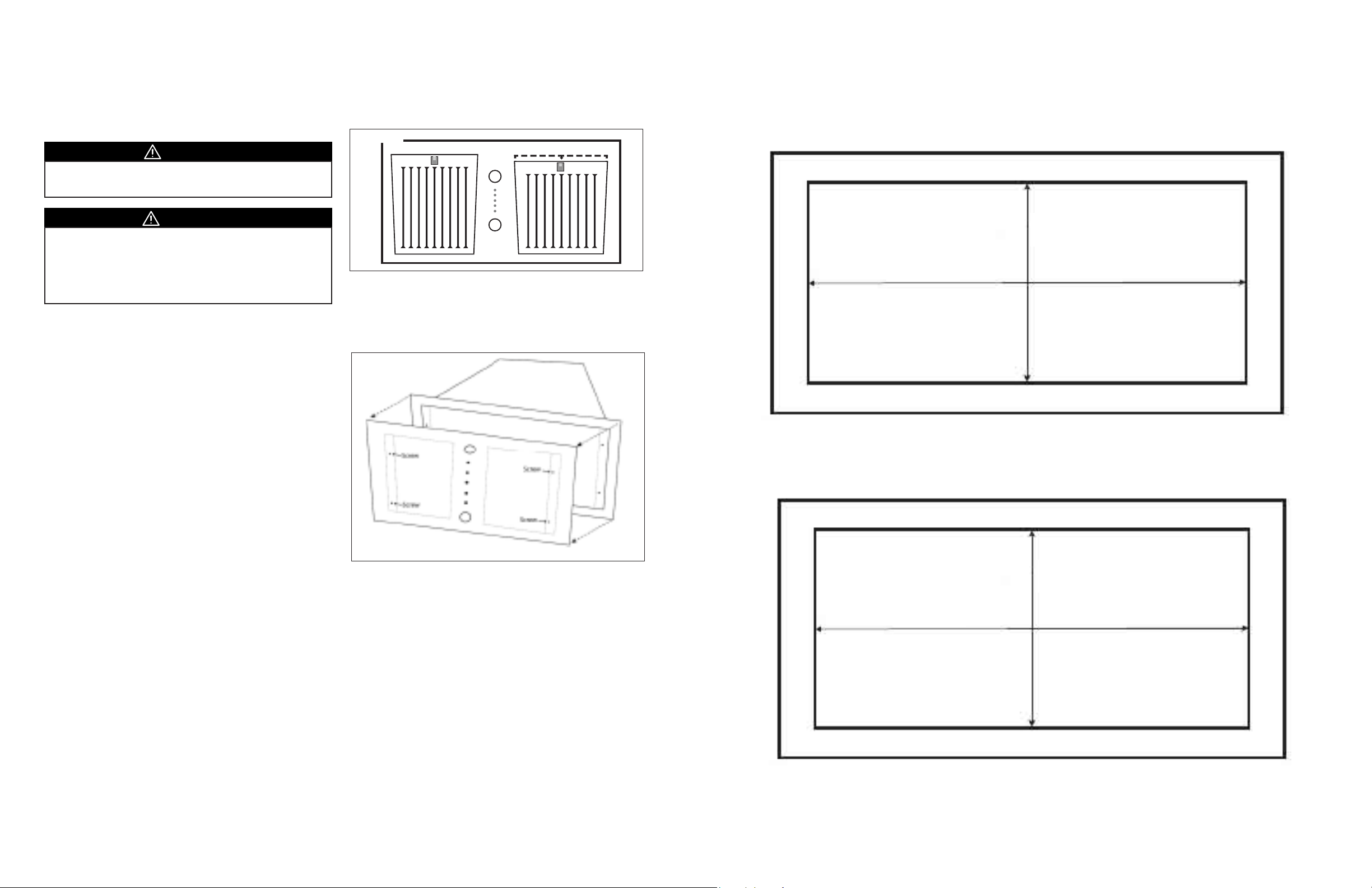
BX600/BX360/CLX60 INSERT HOOD INSTALLATION
Cut Out
Cut Out
BX600/BX360/CLX60 INSTALLATION CUTOUT TEMPLATES
is appliance requires 120V 60Hz electrical supply and
connection to an individual properly grounded branch circuit
protected by a circuit breaker or time delay fuse.
CAUTION
• At least two installers are required due to the weight and
size of the hood.
WARNING
• Turn o power circuit at the service panel before wiring
this unit.
• All electrical work must be done by a qualied electrician
in accordance with all applicable codes and standards.
is range hood must be properly grounded.
Prepare for Installation
1. Unpack range hood and check contents. Note: Be cautious of
sharp edges within the unit.
2. Cut the insert cutout at the bottom of the cabinet using the
given cutout measurements on page 17.
3. Locate the cutout at the center of the bottom of the cabinet.
Install the BX600/BX360/CLX60 Range Hood
1. Remove outer bae lters of range hood (Figure 1).
Figure 1.
2. Hold range hood upright, and insert range hood upward into
cabinet cutout. Mount the insert range hood to the cabinet
using four screws from inside the range hood (two screws on
each side). In addition, use four screws to secure the hood on
to cabinet surface.
Figure 2.
BX60028/BX36028/CLX6028
10 ¼”
26”
16 Cyclone Insert Installation - English
3. By removing the lters, locate the four Phillips screws. ere
are 2 on the right side and 2 on the le side. Remove the 4
screws using your screwdriver or power drill and place them
aside as you will need them later on to reattach the face.
Remove the face and set it aside.. (Figure 2)..
4. Aer removing the four screws, reach into the cavity of the
hood and unplug the two wires that lead to the lights and the
one wire that leads to the switch/controls.
5. Once the three wires are unplugged, you can completely
remove the face and set it aside. With the face removed, you
will be able to identify the four mounting holes that you will
use to secure the hood to the cabinet.
6. Hold range hood upright, and insert range hood upward
into cabinet cutout. Secure the range hood to the cabinet
using the four screws provided. Two for each side.
7. Reattach and screw the face onto range hood. Connect the
connectors of switch and two lights.
8. Make sure that the adapter is connected to ductwork.
9. Place bae lters back into place.
10. Connect the power plug to the junction box.
BX60034/BX36034/CLX6034
13 ⅛”
31 ⅜”
17Cyclone Insert Installation - English
Page 10
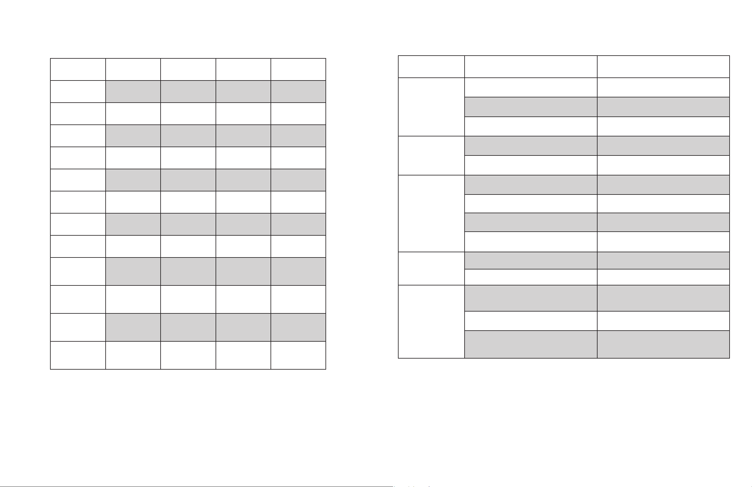
INSERT HOODS SPECIFICATIONS
TROUBLESHOOTING
SIZE
MAX.
CUBIC FEET/METER
(CFM)
MAX. SONES
MOTOR
FINISH
CONTROLS
SPEED LEVELS
FILTERS
BX155 BX212/BX215 BX600/CLX60 SS13024/SS13030
22”
280
4
CENTRIFUGAL CENTRIFUGAL CENTRIFUGAL CENTRIFUGAL
STAINLESS STEEL STAINLESS STEEL STAINLESS STEEL STAINLESS STEEL
PUSH BUTTON SLIDE CONTROL PUSH BUTTON SLIDE CONTROL
3 3 3 3
MESH MESH BAFFLE MESH
BX215-28”/34”
BX212-22"/28"/34”
BX212 - 300
BX215 - 550
BX212 - 4
BX215 - 6
28”/34” 24”/30”
600 300
4 6
ISSUE CAUSE SOLUTION
Unit doesn’t work aer
installation.
Light indicates power
ON but motor doesn’t
turn.
e unit vibrates. 1. e motor is not secured. 1. Tighten the motor in place.
1. e power source is not turned ON. 1. Ensure power is ON for the circuit breaker and
unit.
2. e power line and the cable locking connector
are not connected properly.
3. e unit does not turn on when it is at full
extension (SS130 only).
2. Check the power connection with the unit is
connected properly.
3. Check if the slide control is turned o or set to
0.
1. e motor is defective, possibly seized. 1. Change the motor. Servicing may be required.
2. e motherboard is defective. 2. Change defective part. Servicing may be
required.
2. Damaged blower wheel. 2. Replace the blower wheel. Servicing may be
required.
3. e hood is not secured in place. 3. Check the installation of the hood.
4. Venting duct too small or blockage in the duct
opening or ductwork.
4. Check the venting duct and the wall cap or roof
cap.
DUCT
LIGHTING
AC INPUT
MOUNTING HEIGHT
*Bulb & socket may change.
q
6” ROUND TOP
2 × 120V 25W
Halogen
120V
60Hz
28”-36” 28”-36” 28”-36” 28”-36”
WITH ADAPTOR
6” ROUND TOP
2 × 120V 25W
Halogen
120V
60Hz
WITH ADAPTOR
6” ROUND TOP
2 × 120V 1.4W
LED
120V
60Hz
WITH ADAPTOR
6” ROUND TOP
2 × 12V 1.4W
LED
120V
60Hz
Motor works but lights
do not turn on.
e hood is not venting
out properly.
1. Defective light bulb. 1. Change the light bulb.
2. e light bulb is loose. 2. Tighten the light bulb.
1. e hood might be hanging too high from the
cook top.
1. Adjust the distance between the cook top and
the bottom of the hood within 28” - 36” above
the range.
2. Blockage in the duct opening or ductwork. 2. Remove all the blocking from the duct work or
duct opening.
3. Using the wrong size of ducting. 3. Use at least 6” duct work.
18 Cyclone Insert Installation - English
19Cyclone Insert Installation - English
Page 11
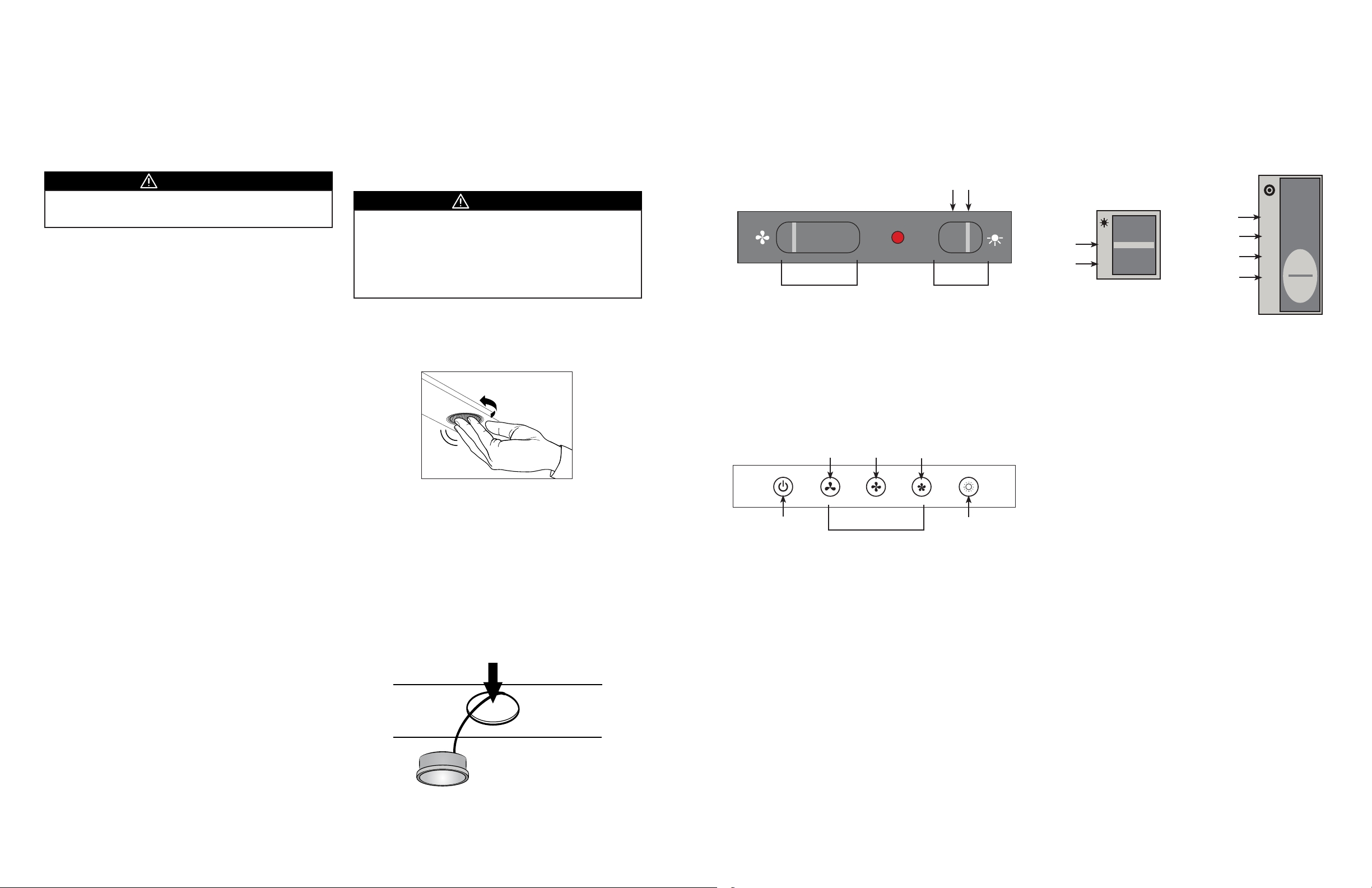
MAINTENANCE
CONTROL PANEL
For a complete description of our maintenance and operating instructions you may visit us online at
www.CycloneRangeHoods.com to download your model’s Use and Care Guide.
Due to the fact that we are always striving to improve our products and take advantage of advances in technology there may
be slight variations in your product.
WARNING
• Always switch o power and unplug before cleaning and
maintenance.
Surface and Filter Cleaning:
Clean with warm soapy water and a clean cloth. Do not use corrosive
or abrasive detergent or steel wool pads that can scratch the surface
of the machine.
Use non-abrasive stainless steel polish to bu out the luster and
grain. Scrub lightly.
e stainless steel lters trap residue and grease from cooking.
e lters should never have to be replaced but should be cleaned
thoroughly every 30 to 60 days depending on cooking habits. Filters
may be placed on the top rack of the dishwasher or soaked in warm,
soapy water.
Spray degreasing detergent and leave to soak if heavily soiled.
Replacing Lightbulbs:
WARNING
• Always switch o electrical supply before carrying out any
operation on the appliance.
• In order to prevent the risk of personal injury, the halogen
lamps must be cooled before removal.
• Use LED bulb, 1.5W maximum per bulb, for SS130.
• *Bulb & socket may change.
To change bulbs for BX212/BX215/BX600/BX360/CLX60
1. Firmly press ngers against the lightbulb and twist counterclockwise until bulb is loosened.
To change bulbs for SS130:
is range hood requires LED bulbs. (1.5W maximum per bulb)
Model: BX212/BX215
e unit is controlled by slide controls.
e fan and light are each controlled by a slide control. e
fan switch has four positions: HIGH, MED, LOW and OFF. e
light switch has two positions, ON and OFF.
ON/OFF
3 2 1 0 1 0
Fan Controls
Light
Model: BX600/BX360/CLX60
e unit is controlled by push buttons.
e fan and lights are each controlled by a push buttons. e
fan switch has four positions: HIGH, MED, LOW and OFF. e
light switch has two positions, ON and OFF.
MED
speed
Fan Controls
HIGH
speed
Light
ON
LOW
speed
Model: SS130
e unit is controlled by slide controls.
e fan and light are each controlled by a slide control. e
fan switch has four positions: HIGH, MED, LOW and OFF. e
light switch has two positions, ON and OFF.
OFF
ON
OFF
0
1
Light
LOW speed
MED speed
HIGH speed
0
1
2
3
Fan Controls
Automatic Operations
Simply pull the front slide out towards yourself and turn the light
switch to “on” and have the fan setting to the desired speed at which
you would like the fan to start (control is found underneath hood
on the right side). Push slide back into place. Now when you pull
the front slide out towards yourself the unit lights and fan should
automatically come on.
To Engage Time-Delay O Functions:
From underneath hood go to slide out and slide the control to the
desired speed. To access light control pull front slide out towards
you and turn the light switch.
20 Cyclone Insert Installation - English
To change the light bulb, remove light case from the light socket.
e light case can be accessed from the inside of the body of the
machine.
i. Disconnect the connecting wires of the light socket from the
motherboard wires.
ii. Remove grease lters and push light case outward away from
the machine.
iii. Replace with a new case.
21Cyclone Insert Installation - English
Page 12

CYCLONE RANGE HOODS LIMITED WARRANTY
Cyclone Range Hoods Inc. (hereunder called “e Company”) provides a warranty that its products are free from defects in
workmanship and materials for a period of two (2) years from the date of purchase. is warranty includes in-home service (where
applicable) for the rst year and workshop service for the second year. During that time period, e Company will, at the Company’s
option, repair or replace without charge any parts or complete unit found to be defective. Further, the warranty for the motor extends
for an additional eight (8) years, with labor costs extra. is warranty is not transferrable from the original purchaser. e company
reserves the right to use functionally equivalent reconditioned parts or products as warranty replacement or as part of warranty service.
THE COMPANY WILL NOT BE HELD RESPONSIBLE FOR ANY CLAIMS OVER THE ORIGINAL PURCHASE PRICE OF
THE PRODUCTS NOR BE LIABLE FOR INCIDENTAL, CONSEQUENTIAL OR SPECIAL DAMAGES ARISING OUT OF OR IN
CONNECTION WITH PRODUCT USE OR PERFORMANCE.
Some provinces do not allow the exclusion or limitation of incidental or consequential damages, so the above limitation or exclusion
may not apply to you.
In-home service will be made available only in areas where a contracted service provider oers services. If customer outside the
service area, additional charges may apply for shipping costs for warranty repair or replacement. e unit removal and reinstallation
works are under the customer responsibility.
is warranty does not cover any costs related to the products including but not limited to:
a) Normal maintenance service required for the products; b) light bulbs, plastic grease collector cups, lters, ducts, roof caps, wall
caps and other accessories for ducting; c) natural wear of the nish of the products or wear caused by improper maintenance, use of
corrosive and abrasive cleaning products; d) products or parts which have been subject to freight damage, misuse, negligence, accident
or any other circumstances beyond the control of e company.
i. e warranty will be automatically void if any of the following apply:
ii. Commercial use of the products or use otherwise inconsistent with its intended purpose;
iii. e function of part or the complete assembly has been modied or repaired by unauthorized person;
iv. Faulty installation or installation contrary to recommended installation instructions:
• e hood installed at less than 28” minimum above the range surface;
• Ventilation system has not been vented to the outside or ventilation system stuck;
• Less than 6” round or equivalent ductwork has been used anywhere in the venting system for models with 550 CFM or
more CFM;
• e venting duct turned downward anywhere in the venting system;
• Wrong electrical wire connection for the fan.
To qualify for warranty service you must: (a) notify us at the address telephone number stated below within 2 days of the discovery of the
defect; (b) provide the model number and serial number; and (c) describe the nature of any defect in the product or part.
At the time of requesting for service, you must present evidence of your proof of purchase and proof of the original purchase date. If
we determine that the warranty exclusions listed above apply or if you fail to provide the necessary documentation to obtain service,
customer will be responsible for all shipping, travel, labor and other costs related to the service.
For warranty services or repair, please contact the dealer from whom you purchased the product or the address shown below.
Tel: 1-888-293-5662 or (416) 293-0933 Fax (416) 293-4793
22 Cyclone Insert Installation - English
North America Range Hoods Inc.
1361 Huntingwood Drive, Unit 16
Scarborough, ON M1S 3J1
Email: [email protected]
Website: www.CycloneRangeHoods.com
V11-17EN
 Loading...