

Page 1
Meijer.com
Page 2
CONGRATULATIONS ON YOUR NEW BIKE!
Cycle Force Group is dedicated to making sure you are
satisfied with your new bicycle and wants to help with any
questions or comments you may have.
DO NOT RETURN THIS PRODUCT TO THE STORE.
PLEASE CONTACT CYCLE FORCE GROUP FOR ASSISTANCE.
VISIT US AT:
WWW.CYCLEFG.COM
FOR CUSTOMER SERVICE VISIT:
WWW.BIKEAIDONLINE.COM
OR CALL US AT:
1-877-BIKEAID
Meijer.com
Page 3
PLEASE RETAIN YOUR SALES RECEIPT
AS PROOF OF PURCHASE
NOTES:
_________________________________________________________________
_________________________________________________________________
_________________________________________________________________
_________________________________________________________________
_________________________________________________________________
_________________________________________________________________
_________________________________________________________________
_________________________________________________________________
Meijer.com
Page 4
####
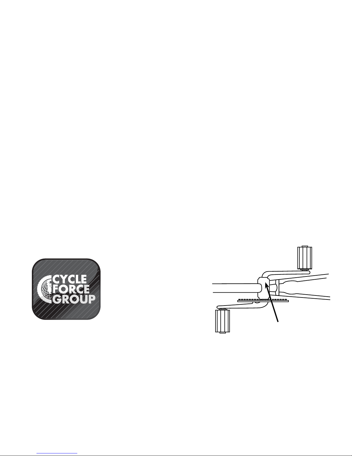
Serial Number Locationn
Bike Shown Upside Down
Serial Number
The following manual is only a guide to assist you and is not a complete or comprehensive manual of all aspects of maintaining and repairing your
bicycle. The bicycle that you have purchased is a complex object. Cycle Force Group recommends that you consult a bicycle specialist if you have
doubts or concerns as to your experience or ability to properly assemble, repair, or maintain your bicycle. You will save time and the inconvenience
of having to go back to the store if you choose to write or call us concerning missing parts, service questions, operating advice, and/or assembly
questions.
Cycle Force Group
2105 SE 5th St.
Ames, IA 50010
Phone: (515) 232-0277
Fax: (515) 232-0279
www.cyclefg.com
Customer Service:
www.bikeaidonline.com
1-877-245-3243
Meijer.com
Page 5
DIRECTORY
PART 1
SECTIONS
PARTS IDENTIFICATION . . . . . . . . . . . . . . 6
BEFORE YOU RIDE . . . . . . . . . . . . . . . 10
ASSEMBLY . . . . . . . . . . . . . . . . . . . . 24
SERVICING . . . . . . . . . . . . . . . . . . . . 58
DETAILED MAINTENANCE . . . . . . . . . . . 62
PART 2
PART 3
PART 4
PART 5
Meijer.com
Page 6
DIRECTORY
PARTS IDENTIFICATION 4
CRUISER/ROAD BICYCLES 4-5
MOUNTAIN/BMX BICYCLES 6-7
TOOLS REQUIRED 8
BEFORE YOU RIDE 10
CORRECT FRAME SIZE 10
RIDING POSITION 11
Saddle Height 11
Reach 11
Handlebar Height 12
SAFETY CHECKLIST 13
1. Brakes 13
2. Wheels and Tires 13
3. Steering 13
4. Chain 13
5. Bearings 14
6. Cranks and Pedals 14
7. Derailleurs 14
8. Frame and Fork 14
9. Accessories 14
Helmets 15
RIDING SAFELY 16
General Rules 16
Wet Weather 17
Night Riding 17
Pedaling Technique 17
Hill Technique 18
Cornering Technique 18
Rules for Children 18
GEARS - HOW TO OPERATE 19
Derailleur Gears 19
Operating Principles 19
Hand Grip Shifters 20
Thumb shifters (Top Mounted) 21
Below the Bar Shifters 21
BICYCLE CARE 22
Basic Maintenance 22
Storage 23
Security 23
ASSEMBLY 24
DERAILLEUR GEARED BICYCLES 24
Getting Started 24
Handlebars 24
Forks 26
Seat and Seat Post 27
Pedals & Cranks Set 28
Front Wheel 29
Correct Quick Release Axle Setting 29
Front Brake 30
Cantilever Brakes – Link Wire 30
Cantilever Brakes – Straddle Cable 32
V-Style Brakes 32
Check your Brakes 35
Disk Brakes 36
DERAILLEUR 38
Rear Derailleur 38
Front Derailleur 39
Dual Suspension 40
Rear Pivots 41
Accessories 42
Reflectors 42
Final Check 43
SINGLE SPEED & BMX 44
Getting Started 44
Handlebars 44
Seat 45
Pedals & Crank Set 45
Front Wheel 46
Front Brake 46
Side Pull Brake 48
Cantilever Brakes – Link Wire 48
Cantilever Brakes – Straddle Cable 52
Check your Brakes 53
Training Wheels 53
Rotors 54
Final Check 56
SERVICING 58
ROUTINE MAINTENANCE 58
Schedule 1 - Lubrication 58
Schedule 2 - Service Checklist 59
Tools Required 60
Travel Tools 60
DETAILED MAINTENANCE 62
WHEELS AND TIRES 62
Wheel Inspection 62
Tire Inspection 63
Recommended Tire Pressures: 63
Hub Bearing
Adjustment 64
How To Fix a Flat Tire 64
HANDLEBARS AND STEM 66
Handlebar Stem 66
WARNING 66
Handlebars 67
TWIST SHIFTERS 68
Twist Shift – Installation 68
Cables and Cable Housing 69
HEADSET 70
Inspection 70
Adjustment 70
SUSPENSION FORK 71
Regular Maintenance 71
Reassembly 71
Check before each ride: 71
SADDLE AND SEAT POST 72
Inspection 72
Lubrication 72
Adjustment 73
Brakes 74
Inspection 74
Lubrication 75
Adjustment – Sidepull Calipers 75
Adjustment – Cantilever Calipers 76
DRIVETRAIN 78
Pedals 78
Inspection 78
Attachment 79
Lubrication and Adjustment 79
CRANK SET 80
Inspection 80
Lubrication and Adjustment – One Piece
Cranks 81
Lubrication and Adjustment – Cotterless
Cranks 82
Lubrication 84
Adjustment and Replacement 84
Chain 84
Inspection 84
FREEWHEEL 85
Inspection 85
Lubrication 86
COASTER HUB 86
DERAILLEUR SYSTEMS 87
Inspection 87
Lubrication 88
Adjustment – Rear Derailleur 88
Adjustment – Front Derailleur
Quick Release Levers
8909
Meijer.com
Page 7
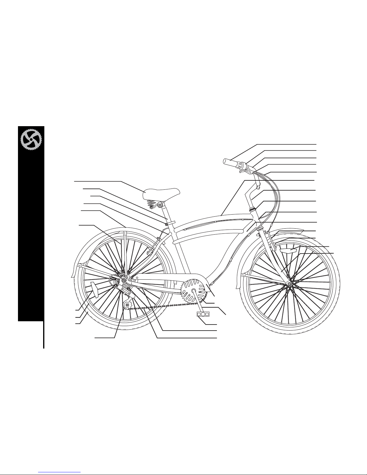
CRUISER BICYCLE
Cruiser bicycles also known as beach cruisers are designed for comfort and style.
PARTS IDENTIFICATION
Seat
Handlebar Grip
Shifter
Handlebars
Handlebar Stem
Head Set
Head Tube
Top Tube
Brake Lever
Brake Control Cables
Seat Post
Quick Release
Seat stays
Rear Derailleur Chain
Chainstay
Pedal
Crank Arm
Chainwheel
Fenders
Spokes
Chainguard
Down Tube
Front Brake
Brake Pad
Wheel Reflector
Fork
Tire
Rim
Rear Reflector
Meijer.com
Page 8
5
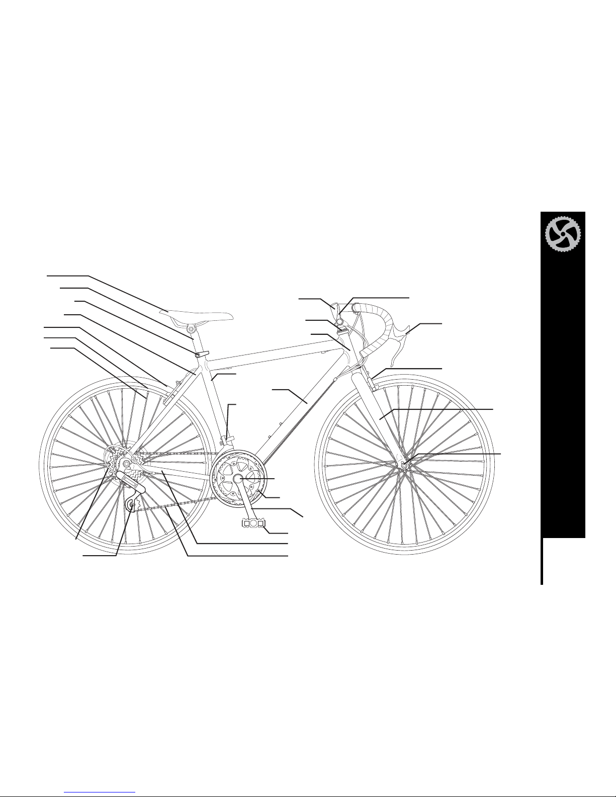
PARTS IDENTIFICATION
ROAD BICYCLE
Road bicycles are designed for racing and exercise. It can be valued as a commuter if long distance or speed is required.
Road bicycles use narrow, high-pressured tires to decrease rolling resistance and equipped with drop handlebars.
Seat Post
Seat
Quick Release
Seat stays
Rear Derailleur
Gear Control Cable
Chain
Chainstay
Pedal
Crank Arm
Chainwheel
Front Derailleur
Bottom
Bracket Axle
Tire
Rim
Spoke
Seat Tube
Down Tube
Head Tube
Head Set
Brake Lever
Shifter
Brake
Fork
Front Hub
Handlebar Stem
Meijer.com
Page 9
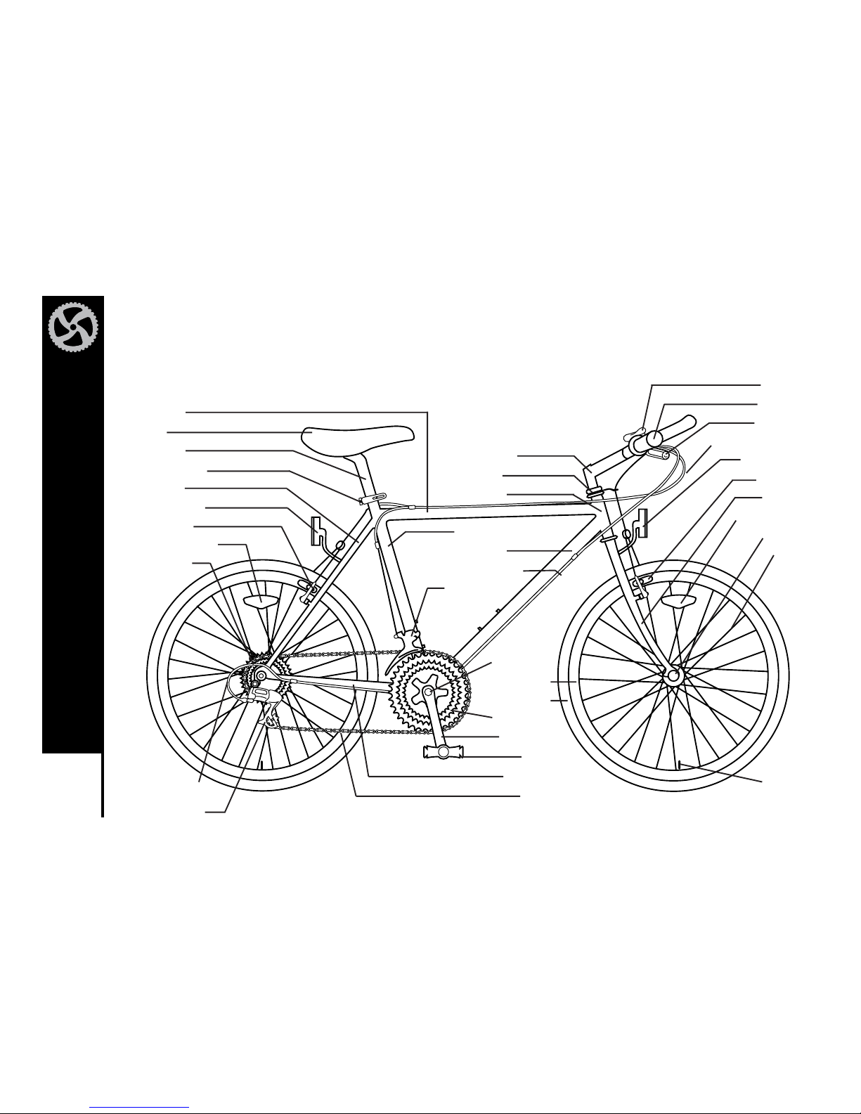
MOUNTAIN BICYCLE
Mountain bicycles are designed to give maximum comfort over a wide variety of road surfaces. The wider handlebars and convenient
shift lever position make them very easy to control. Wider rims and tires give them a softer ride with more traction on rough surfaces.
The frame and fork on mountain style bicycles are much sturdier than those on racing style bicycles.
Top Tube
Seat
Seat Post
Quick Release
Seat Stay
Rear Reflector
Rear Brake
Wheel Reflector
Freewheel
Shift Lever
Handlebar
Brake Lever
Brake Control Cables
Front Reflector
Front Brake
Front Fork
Wheel Reflector
Front Hub
Spokes
Handlebar Stem
Head Set
Head Tube
Seat Tube
Down Tube
Gear Control Cable
Front Derailleur
Bottom
Bracket Axle
Rim
Tire
Chain Wheel
Crank Arm
Pedal
Chainstay
Chain
Tire Valve
Rear Derailleur
Gear Control
Cable
66666
PARTS IDENTIFICATION
Meijer.com
Page 10
7
PARTS IDENTIFICATION
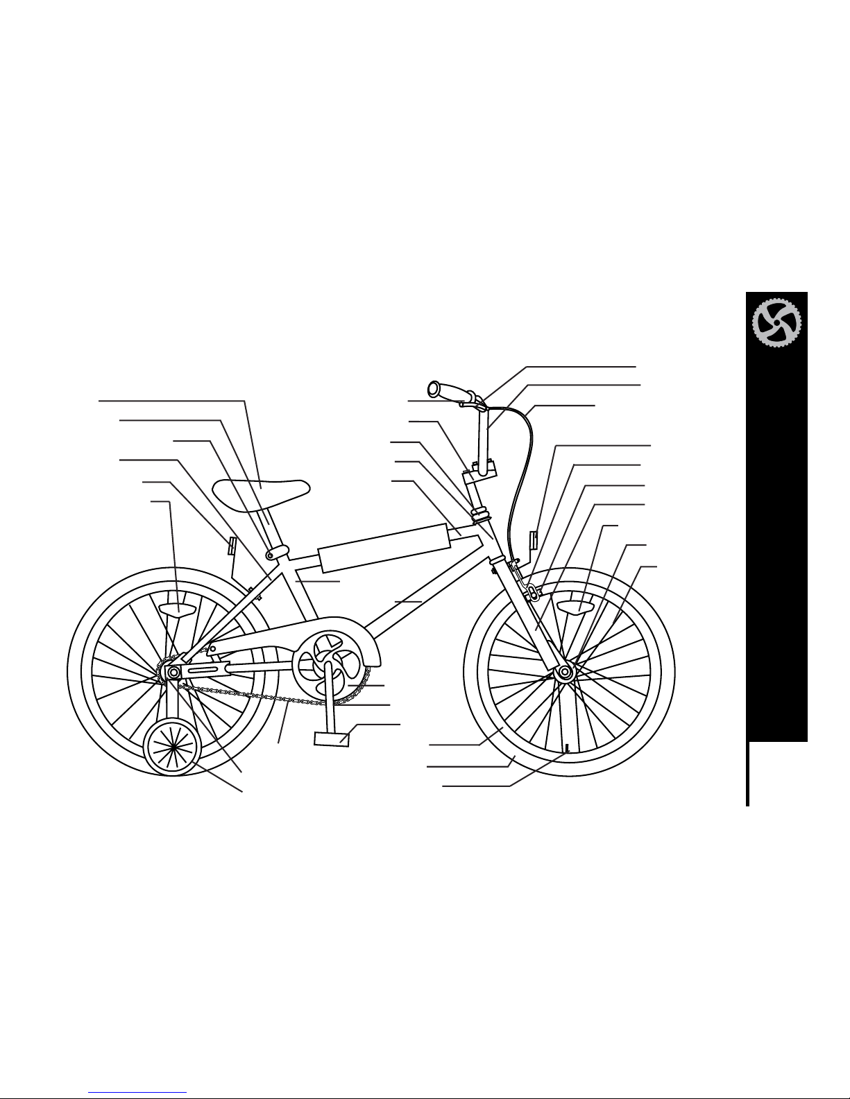
BMX BICYCLE
BMX style bicycles are a popular general purpose type most suited for young riders. They are valued because of their sturdy and simple
construction, and low maintenance.
Seat
Seat Post
Seat Post Binder Bolt
Seat Stay
Rear Reflector
Wheel Reflector
Chain Wheel
Crank Arm
Pedal
Rim
Tire
Tire Valve
Chain
Rear Sprocket
Training Wheels
Brake Lever
Handlebar
Brake Control Cable
Reflector
Front Brake
Brake Pad
Front Fork
Wheel Reflector
Front Hub
Spokes
Handlebar Grip
Handlebar Stem
Head Set
Head Tube
Top Tube
Seat Tube
Down Tube
Meijer.com
Page 11
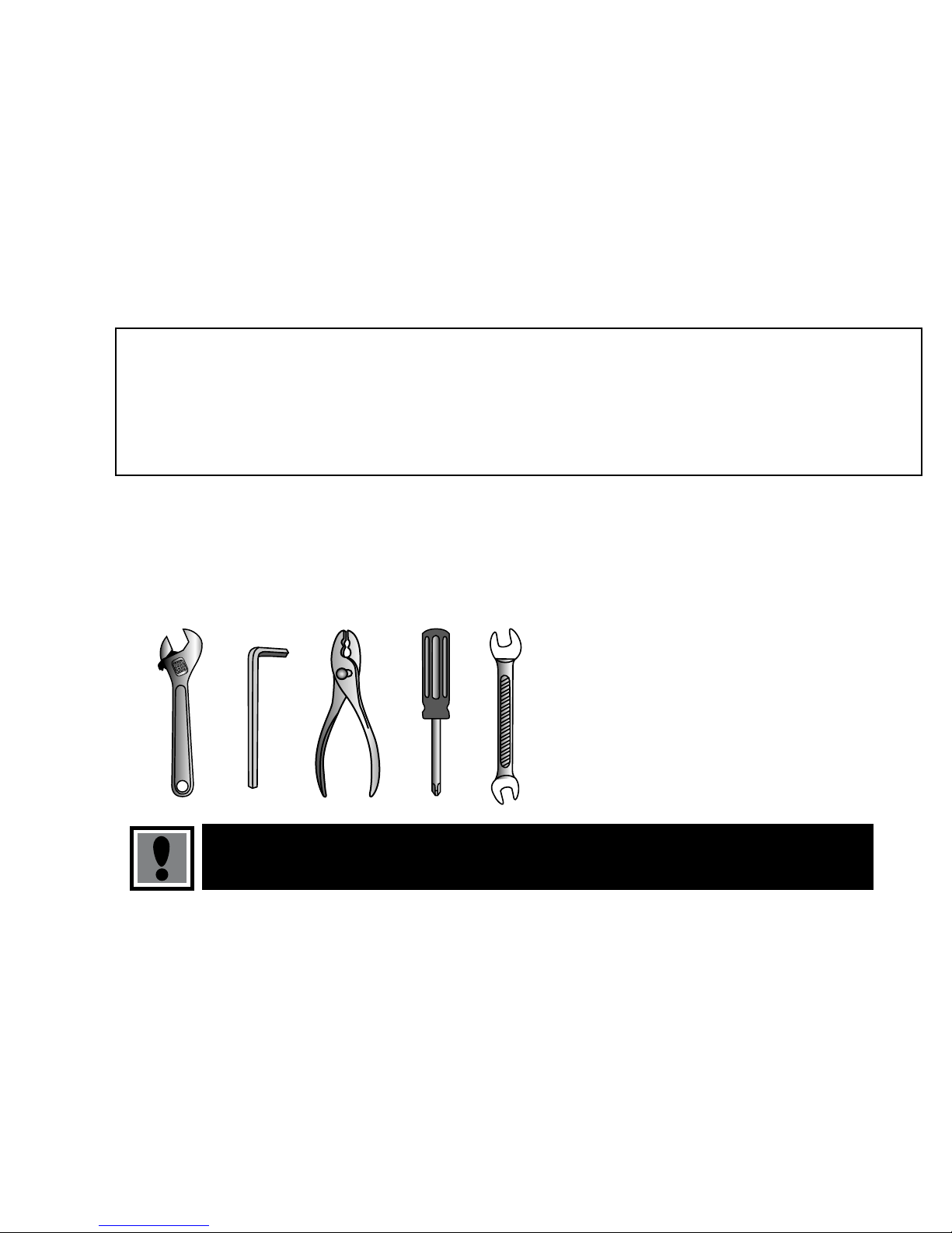
TOOLS REQUIRED
Your new bicycle was assembled and tuned in the factory and then partially disassembled for shipping. You may
have purchased the bicycle already fully reassembled. The following instructions will enable you to prepare your
bicycle for years of enjoyable cycling. For more details on inspection, lubrication, maintenance and adjustment
of any area, please refer to the relevant sections in this manual. If you need replacement parts or have any
questions pertaining to assembly of your bicycle, call Cycle Force Group Bicycles direct at:
CYCLE FORCE GROUP BICYCLES SERVICE AND TECHNICAL SUPPORT:
1-877-245-3243
Monday – Friday 8:00 am – 5:00 pm Central Time
To avoid injury, this product must be properly assembled before use. If your bicycle was obtained assembled, we
strongly recommend that you review the complete assembly instructions, and perform checks specified in this
manual before riding.
Tools Required:
Phillips head screwdriver; 4mm, 5mm, 6mm and 8mm Allen
Keys; adjustable wrench or a 9mm, 10mm, 14mm and
15mm open and box end wrenches; and a pliers with cable
cutting ability.
Meijer.com
Page 12
BEFORE YOU RIDE
9
Meijer.com
Page 13
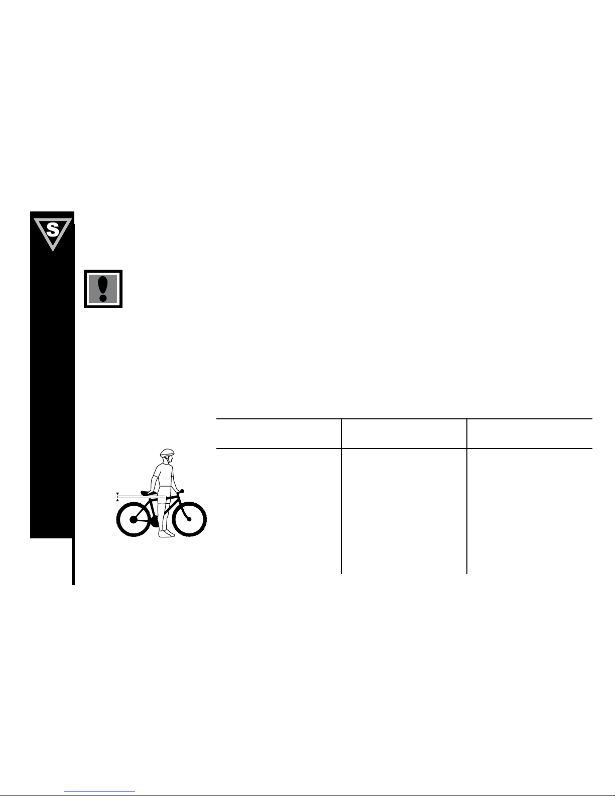
CORRECT FRAME SIZE
When selecting a new bicycle, the correct choice of frame size is a very important safety consideration. Most full sized bicycles come in
a range of frame sizes. These sizes usually refer to the distance between the center of the bottom bracket and the top of the frame seat
tube.
For safe and comfortable riding there should be a clearance of between 25mm and 50mm between the groin area of
the intended rider and the top tube of the bicycle frame, while the rider straddles the bicycle with both feet flat on
the ground.
The ideal clearance will vary between types of bicycles and rider preference. This makes straddling the frame when off the saddle easier
and safer in situations such as sudden traffic stops. Women can use a men’s style bicycle to determine the correct size of the women’s
model.
The following chart and diagram will help you make the correct choice.
Approximate Rider Leg
Length
Suggested Frame Size for
Racing/Touring Bicycle
Suggested Frame Size for
Mountain or Hybrid Bicycle
24 – 27 inches / 61 – 69cm – 14.5 inches / 37cm
26 – 30 inches / 66 – 76cm – 17 inches / 43cm
28 – 31 inches / 71 – 79cm 19.5 inches / 50cm 18 inches / 45cm
30 – 33 inches / 76 – 84cm 21.5 inches / 55cm 19.5 inches / 50cm
31 – 34 inches / 79 – 86cm 22.5 inches / 57cm 20.5 inches / 52cm
32 – 35 inches / 81 – 89cm 23.5 inches / 60cm 21–22 inches / 53 – 56cm
34 – 37 inches / 86 – 94cm 25 inches / 63 cm 23 – 23.5 inches / 58 – 60cm
not less than 1 inch
10
BEFORE YOU RIDE
Meijer.com
Page 14
11
BEFORE YOU RIDE
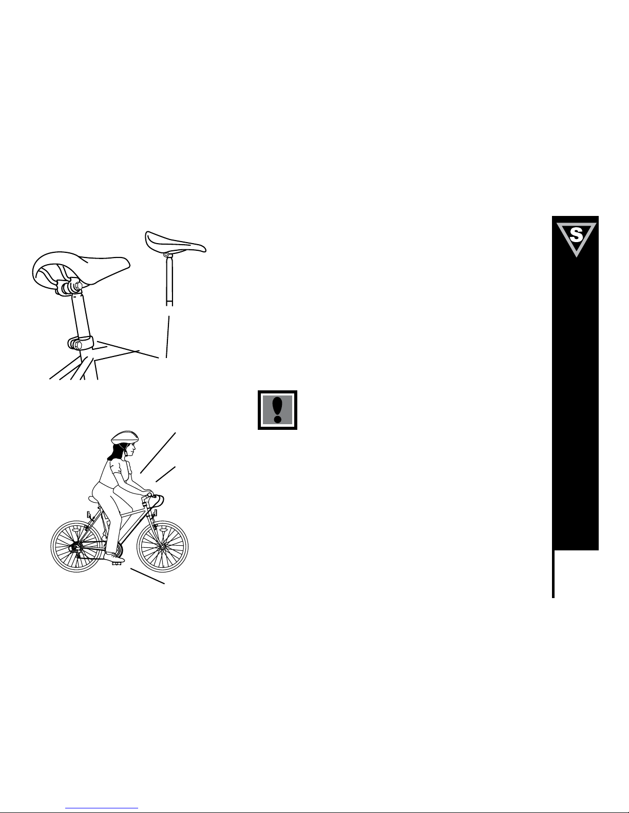
RIDING POSITION
Saddle Height
In order to obtain the most comfortable riding position and offer the best
possible pedaling efficiency, the seat height should be set correctly in
relation to the rider’s leg length. The correct saddle height should not allow
leg strain from over extension, and the hips should not rock from side
to side while pedaling. While sitting on the bicycle with one pedal at its
lowest point, place the ball of your foot on that pedal. The correct saddle
height will allow the knee to be slightly bent in this position. If the rider then
places the heel of that foot on the pedal, the leg should be almost straight.
Ensure that the seat pillar does not extend beyond the
minimum insertion mark.
(Refer to p.72 on how to adjust seat height.)
Reach
To obtain maximum comfort, the rider should not overextend his or her
reach when riding.
To adjust this distance, the position of the seat can be altered in relation to
the seat pillar. (Refer to p.72 on how to adjust the seat clamp.)
Maximum Height /
Mini
mum Insertion Mark
(Should not be visible)
Arms not
over-
extended
Handlebar stem
height about the
same as
seat height
Pedal at
bottom position
Meijer.com
Page 15
12
BEFORE YOU RIDE
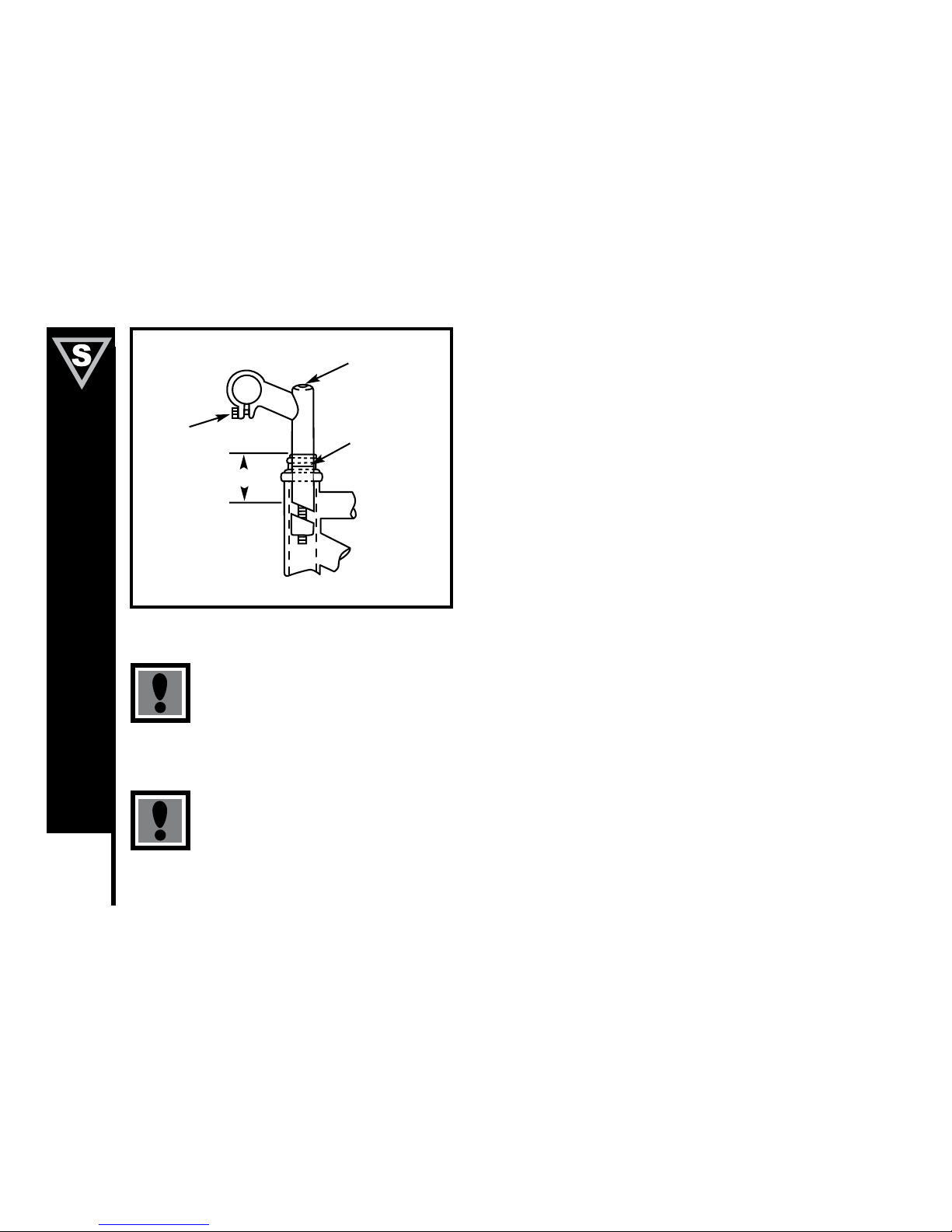
Handlebar Height
Maximum comfort is usually obtained when the handlebar height is equal to
the height of the seat. You may wish to try different heights to find the most
comfortable position.
Ensure that the handlebar stem does not extend beyond the minimum
insertion mark. Failure to do this may cause serious bodily injury
or damage to the bicycle. Ensure both the Stem Wedge Bolt and the
Handlebar Binder Bolt are tightened securely. Failure to do this may cause
loss of steering control. (Refer to p. 67 on how to adjust handlebars).
Warning: Overtightening the stem bolt or headset assembly may cause
damage to the bicycle and/or injury to the rider.
Stem Wedge Bolt
Maximum Height/
Minimum Insertion
Mark
Handlebar Binder Bolt
Exceeds 2 1/2
(64mm)
Meijer.com
Page 16
13
BEFORE YOU RIDE
SAFETY CHECKLIST
Before every ride, it is important to carry out the following safety checks:
1. Brakes
– Ensure front and rear brakes work properly.
– Ensure brake shoe pads are not over worn and are correctly positioned in relation to the rims.
– Ensure brake control cables are lubricated, correctly adjusted, and display no obvious wear.
– Ensure brake control levers are lubricated and tightly secured to the handlebar.
2. Wheels and Tires
– Ensure tires are inflated to within the maximum recommended limit as displayed on the tire side wall.
– Ensure tires have tread and have no bulges or excessive wear.
– Ensure rims run true and have no obvious wobbles or kinks.
– Ensure all wheel spokes are tight and not broken.
– Check that axle nuts are tight. If your bicycle is fitted with quick release axles, make sure locking levers are correctly
tensioned and in the closed position.
3. Steering
– Ensure handlebar and stem are correctly adjusted and tightened, and allow proper steering.
– Ensure that the handlebars are set correctly in relation to the forks and the direction of travel.
– Check that the head set locking mechanism is properly adjusted and tightened.
– If the bicycle is fitted with handlebar end extensions, ensure they are properly positioned and tightened.
4. Chain
– Ensure chain is oiled, clean and runs smoothly.
– Extra care is required in wet or dusty conditions.
Meijer.com
Page 17
14
BEFORE YOU RIDE
5. Bearings
– Ensure all bearings are lubricated, run freely and display no excess movement, grinding or rattling.
– Check headset, wheel bearings, pedal bearings and bottom bracket bearings.
6. Cranks and Pedals
– Ensure pedals are securely tightened to the cranks.
– Ensure cranks are securely tightened to the axle and are not bent.
7. Derailleurs
– Check that front and rear mechanisms are adjusted and function properly.
– Ensure control levers are securely attached.
– Ensure derailleurs, shift levers and control cables are properly lubricated.
8. Frame and Fork
– Check that the frame and fork are not bent or broken.
– If either are bent or broken, they should be replaced.
9. Accessories
– Ensure that all reflectors are properly fitted and not obscured.
Meijer.com
Page 18
15
BEFORE YOU RIDE
Helmets
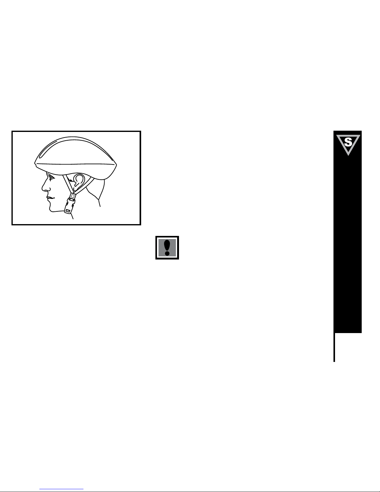
It is strongly advised that a properly fitting, ANSI or SNELL approved,
bicycle safety helmet be worn at all times when riding your bicycle. In
addition, if you are carrying a passenger in a child safety seat, they must
also be wearing a helmet.
The correct helmet should:
- be comfortable
- be lightweight
- have good ventilation
- fit correctly
Always wear a properly fitted helmet when riding a
bicycle.
Meijer.com
Page 19
16
BEFORE YOU RIDE
RIDING SAFELY
General Rules
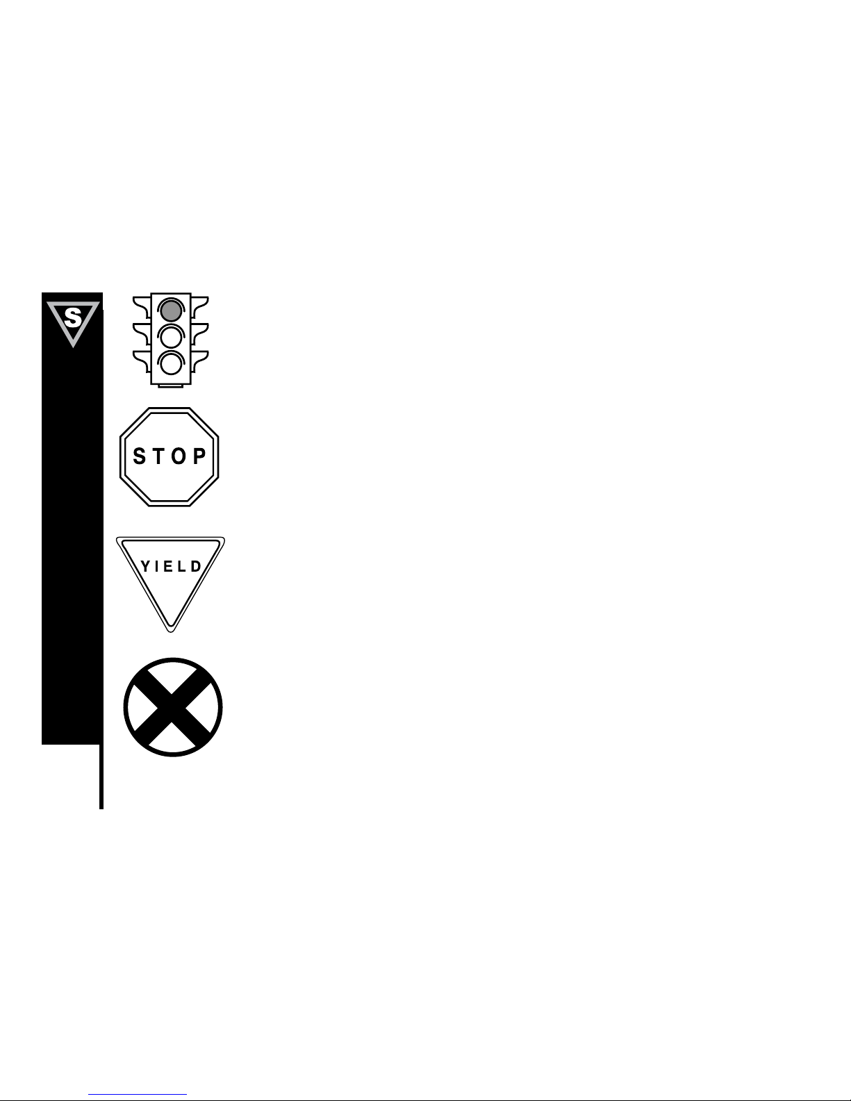
When riding obey the same road laws as all other road vehicles, including giving way to pedestrians, and
stopping at red lights and stop signs.
For further information, contact the Road Traffic Authority in your State.
Ride predictably and in a straight line. Never ride against traffic.
Use correct hand signals to indicate turning or stopping.
Ride defensively. To other road users, you may be hard to see.
Concentrate on the path ahead. Avoid pot holes, gravel, wet road markings, oil, curbs, speed bumps, drain
grates and other obstacles.
Cross train tracks at a 90 degree angle or walk your bicycle across.
Expect the unexpected such as opening car doors or cars backing out of concealed driveways.
Be extra careful at intersections and when preparing to pass other vehicles.
Familiarize yourself with all the bicylce’s features. Practice gear shifts, braking, and the use of toe clips and
straps, if fitted.
If you are wearing loose pants, use leg clips or elastic bands to prevent them from being caught in the chain.
Don’t carry packages or passengers that will interfere with your visibility or control of the bicycle. Don’t use
items that may restrict your hearing.
When braking, always apply the rear brake first, then the front. The front brake is more powerful and if it is not
correctly applied, you may lose control and fall.
Maintain a comfortable stopping distance from all other riders, vehicles and objects.
Safe braking distances and forces are subject to the prevailing weather conditions.
Meijer.com
Page 20
17
BEFORE YOU RIDE
Wet Weather
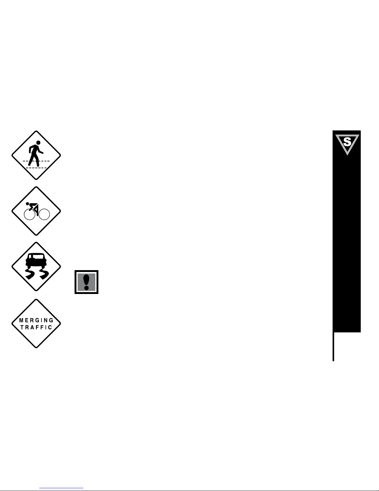
– In wet weather you need to take extra care.
– Brake earlier, you will take a longer distance to stop.
– Decrease your riding speed, avoid sudden braking, and take corners with additional caution.
– Be more visible on the road.
– Wear reflective clothing and use safety lights.
– Pot holes and slippery surfaces such as line markings and train tracks all become more hazardous when
wet.
Do not ride at night, unless it is absolutely necessary.
Night Riding
– Ensure bicycle is equipped with a full set of correctly positioned and clean reflectors.
– Use a properly functioning lighting set comprising of a white front lamp and a red rear lamp.
– If using battery powered lights, make sure batteries are well charged.
– Some rear lights available have a flashing mechanism which enhances visibility.
– Wear reflective and light colored clothing.
– Ride at night only if necessary. Slow down and use familiar roads with street lighting, If possible.
Pedaling Technique
– Position the ball of your foot on the center of the pedal.
– When pedaling, ensure your knees are parallel to the bicycle frame.
– To absorb shock, keep your elbows slightly bent.
– Learn to operate the gears properly. (Refer to p. 19-21)
Meijer.com
Page 21
18
BEFORE YOU RIDE
Hill Technique
– Gear down before a climb and continue gearing down as required to maintain pedaling speed.
– If you reach the lowest gear and are struggling, stand up on your pedals. You will then obtain more power from each pedal
revolution.
– On the descent, use the high gears to avoid rapid pedaling.
– Do not exceed a comfortable speed, maintain control and take additional care.
Cornering Technique
Brake slightly before cornering and prepare to lean your body into the corner. Maintain the inside pedal at the 12 o’clock position and
slightly point the inside knee in the direction you are turning. Keep the other leg straight, don’t pedal through fast or tight corners.
Rules for Children
To avoid accidents, teach children good riding skills with an emphasis on safety from an early age.
1. Always wear a properly fitted helmet.
2. Do not play in driveways or the road.
3. Do not ride on busy streets.
4. Do not ride at night.
5. Obey all the traffic laws, especially stop signs and red lights.
6. Be aware of other road vehicles behind and nearby.
7. Before entering a street: Stop, look right, left, and right again for traffic. IF there’s no traffic, proceed into the roadway.
8. If riding downhill, be extra careful. Slow down using the brakes and maintain control of the steering.
9. Never take your hands off the handlebars, or your feet off the pedals when riding downhill.
The Consumer Protection Safety Commission advises that the riding of small wheel diameter bicycles at excessive
speeds can lead to instability and is not recommended.
Children should be made aware of all possible riding hazards and correct riding behavior before they take to the streets
- Do not leave it up to trial and error
Meijer.com
Page 22
19
BEFORE YOU RIDE
GEARS - HOW TO OPERATE
Derailleur Gears
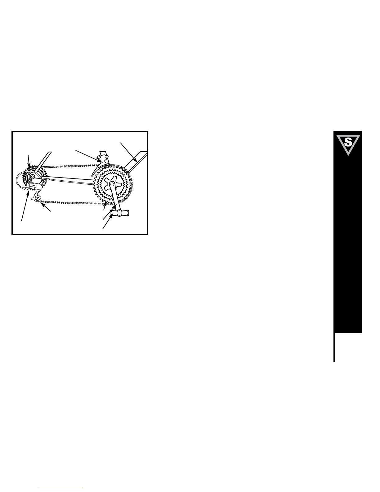
Most multi-speed bicycles today are equipped with what are known as
derailleur gears. They operate using a system of levers and mechanisms
to move the drive chain between different sized driving gears or cogs.
The purpose of gears is to let you maintain a constant, steady pedaling
pace under varying conditions. This means your riding will be less tiring
without unnecessary straining up hills or fast pedaling downhill. Bicycles
come with a variety of gear configurations from 5 to 27 speeds. A 5-6
speed bicycle will have a single front chainwheel, a rear derailleur, and 5
or 6 cogs on the rear hub. Bicycles with more gears will also have a front
derailleur, a front chainwheel with 2-3 cogs, and up to 9 cogs on the rear
hub.
Operating Principles
No matter how many gears, the operating principles are the same. The
front derailleur is operated by the left shift lever and the rear derailleur
by the right. To operate you must be pedaling forward. You can not shift
derailleur gears when you are stopped or when pedaling backwards.
Before shifting ease up on your pedaling pressure. On approaching
a hill, shift to a lower gear before your pedaling speed slows down too
much for a smooth shift. When coming to a stop, shift to a lower gear
first so it will be easier when you start riding again. If, after selecting a
new gear position, you hear a slight rubbing noise from the front or rear
gears, gently adjust the appropriate shifter until the noise goes away. For
optimal performance and extended chain life, it is recommended that you
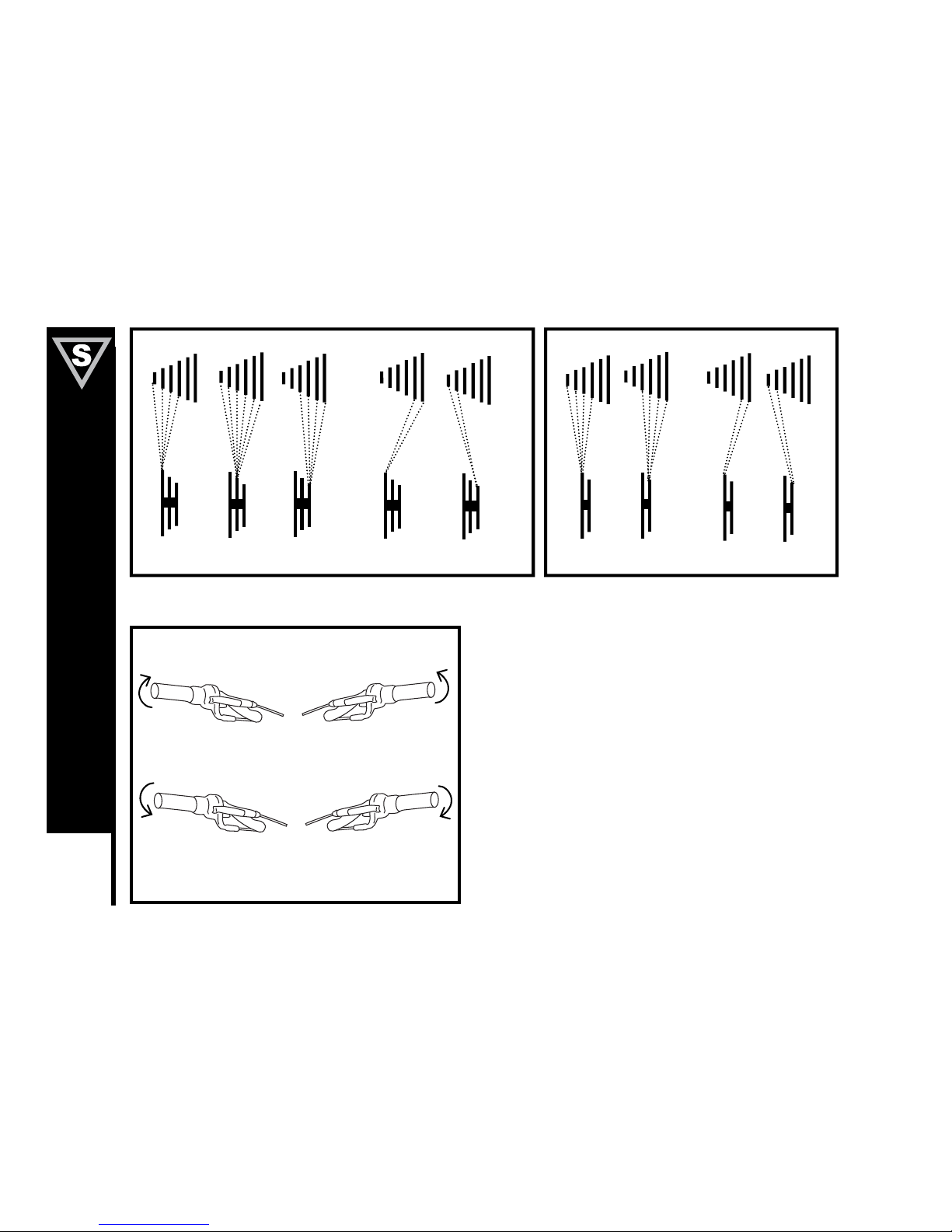
avoid using the extreme combinations of gear positions (diagram p. 20) for
extended periods.
Front Derailleur
Guide Pulley
Rear Derailleur
Front Chainwheels
Crank Arm
Pedal
Derailleur Control
Cable
Freewheel
Cogs
Meijer.com
Page 23
20
BEFORE YOU RIDE
Recommended Chainwheel/Rear Sprocket Gear Combinations
Hand Twist Shifters
Some bicycles are now being equipped with a shifting mechanism called
Twist Shift, which is built into the handlebar grips and does not make use of
separate levers. The actuating mechanism is built into the inside part of the
grip that the web of the thumb and index finger closes around. To select a
lower gear, twist the right shifter toward you to engage a larger rear cog. You
can shift one gear at a time by moving the Twist Shift one click, or through
multiple gears by continued twisting. By twisting the left shifter forward or
away from you, a smaller chainwheel can be selected. To select a higher
gear, twist the right shifter forward or away from you to engage a smaller
rear cog. To engage a larger front chainwheel, twist the left shifter towards
you. Single shifts can be achieved by twisting one click at a time and
multiple shifts by larger twists.
6
5
4
3
2
1
6
5
4
3
2
1
3
2
1
High
Middle Low
2
High
1
Low
For optimal performance,
NOT RECOMMENDED
For optimal performance,
NOT RECOMMENDED
Front Low Gear Rear Low Gear
Front High Gear Rear High Gear
Meijer.com
Page 24
21
BEFORE YOU RIDE
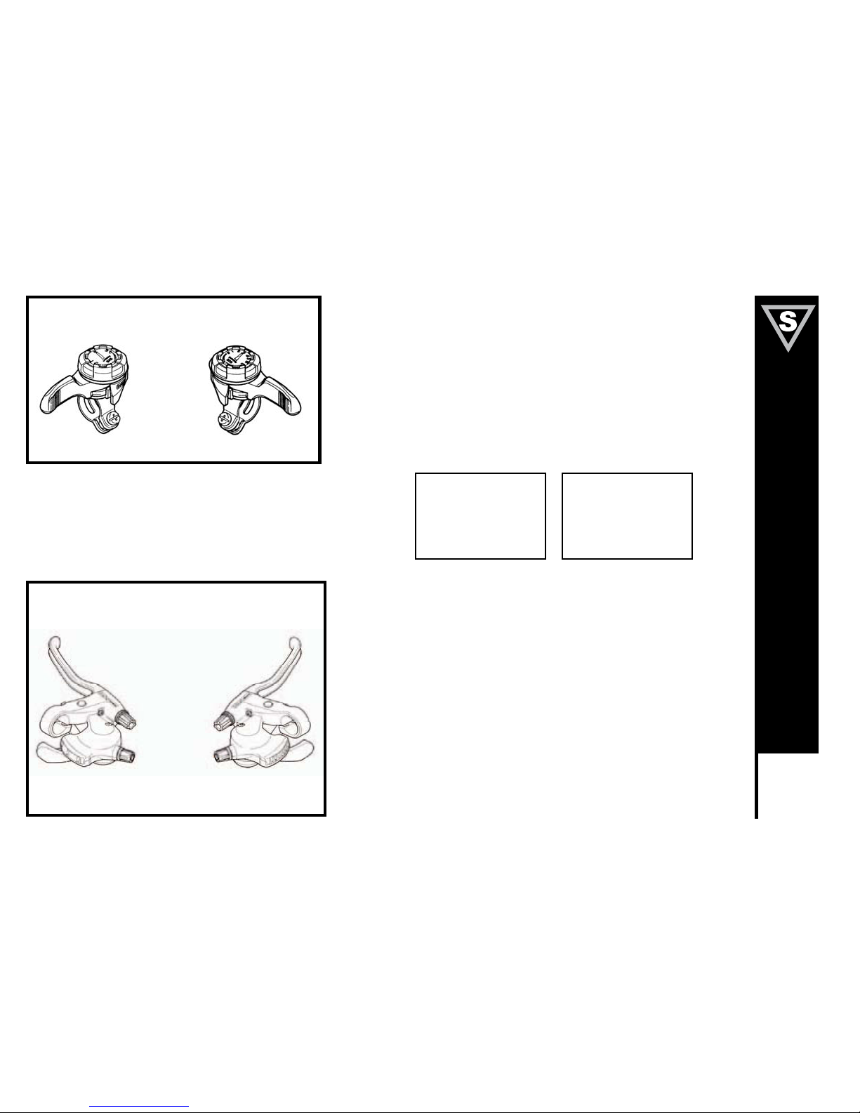
Thumb shifters (Top Mounted)
Most mountain style bicycles are equipped with shifters mounted on the
top of the handlebars and operated by the thumbs. To select a lower,
easier gear, shift to a bigger rear cog and a small chainwheel. Pull the left
shifter back to operate the derailleur. To select a higher, harder gear, shift
to a smaller rear cog and a larger chainwheel. Push the left shifter forward
for the front, and pull the right lever back for the rear.
Below the Bar Shifters
Many mountain style bicycles now use a shift lever arrangement mounted
on the underside of the handlebars, which use two levers operated by the
thumb and index finger. To select a lower gear push the larger (lower)
right shifter with your thumb to engage a larger rear cog. One firm push
shifts the chain one cog, continuing to push will move the chain over
multiple cogs. Pulling the smaller (upper) left shifter with your index finger
moves the chain from a larger to a smaller chainwheel. To select a higher
gear pull the smaller (upper) right lever with your index finger to engage a
smaller rear cog. Pushing the larger (lower) left lever with your thumb will
move the chain from a smaller to a larger chainwheel.
Left hand lever Right hand lever
Left hand lever Right hand lever
Top Gear
(Harder)
Small rear sprocket
Large chainwheel
Left hand lever forward
Right hand lever back
Bottom Gear
(Easier)
Large rear sprocket
Small chainwheel
Left hand lever back
Right hand lever forward
Meijer.com
Page 25
22
BEFORE YOU RIDE
BICYCLE CARE
Basic Maintenance
The following procedures will help you maintain your bicycle for years of enjoyable riding.
For painted frame, dust the surface and remove any loose dirt with a dry cloth. To clean, wipe with a damp cloth soaked in a mild
detergent mixture. Dry with a cloth and polish with car or furniture wax. Use soap and water to clean plastic parts and rubber tires.
Chrome plated bikes should be wiped over with a rust preventative fluid.
Store your bicycle under shelter. Avoid leaving it in the rain or exposed to corrosive materials. Riding on the beach or in coastal areas
exposes your bicycle to salt, which is very corrosive. Wash your bicycle frequently and wipe or spray all the unpainted parts with an
anti-rust treatment. Make sure wheel rims are dry so braking performance is not affected. After rain, dry your bicycle and apply anti-rust
treatment.
If the hub and bottom bracket bearings of your bicycle have been submerged in water, they should be taken out and re-greased. This
will prevent accelerated bearing deterioration.
If paint has become scratched or chipped to the metal, use touch up paint to prevent rust. Clear nail polish can also be used as a
preventative measure.
Regularly clean and lubricate all moving parts, tighten components and make adjustments as required. (Refer to Parts 4 and 5 of this
manual for further details).
The use of alloy components, SATIN, and TITANIUM surface treatments minimizes the number of places where rust can
surface.
Meijer.com
Page 26
23
BEFORE YOU RIDE
Storage
Keep your bicycle in a dry location away from the weather and the sun.
Ultraviolet rays may cause paint to fade or rubber and plastic parts to
crack.
Before storing your bicycle for a long period of time, clean and lubricate
all components and wax the frame. Deflate the tires to half pressure and
hang the bicycle off the ground. Don’t store near electric motors as ozone
emissions may affect the rubber and paint. Don’t cover with plastic, as
“sweating” will result, which may cause rusting.
Security
It is advisable that the following steps be taken to prepare for and help
prevent possible theft.
1. Maintain a record of the bicycle’s serial number, generally located on
the frame underneath the bottom bracket.
2. Register the bicycle with the local police.
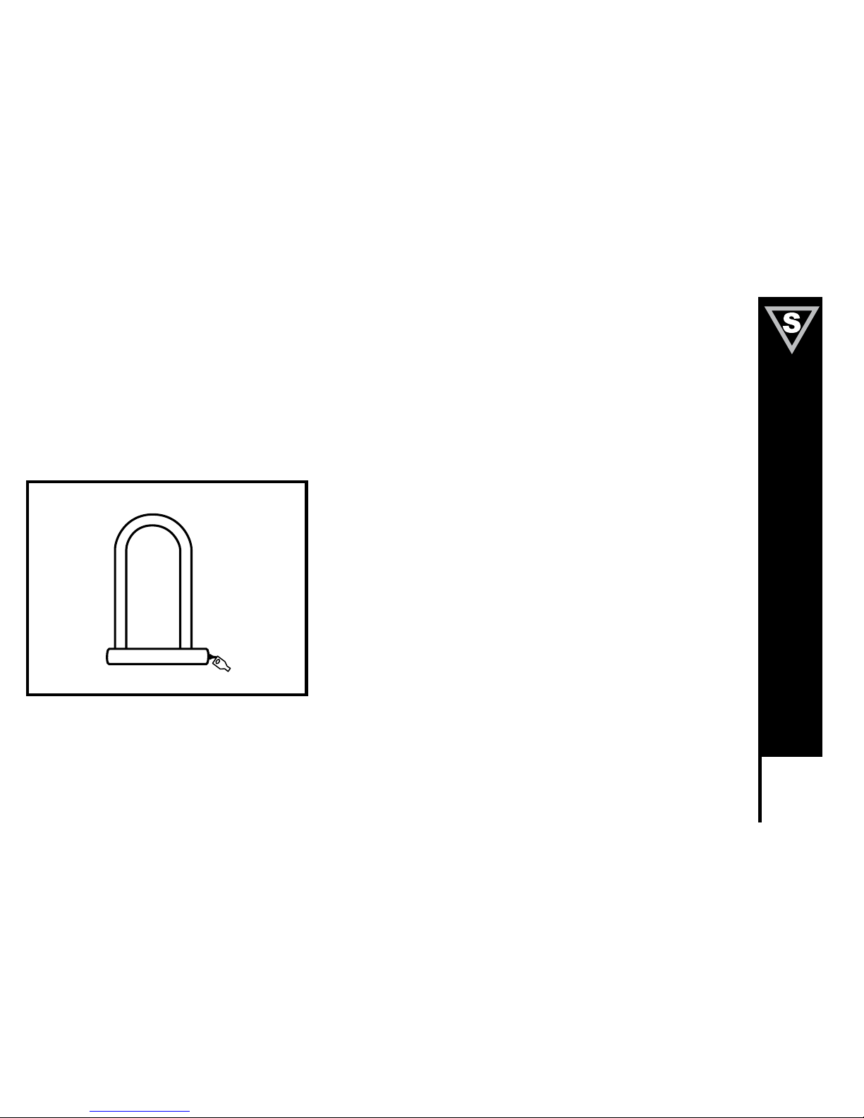
3. Invest in a high quality bicycle lock that will resist hacksaws and
bolt cutters. Always lock your bicycle to an immovable object if it is
left unattended.
Meijer.com
Page 27
DERAILLEUR GEARED BICYCLES
Includes 20”, 24”, 26” Wheel Mountain Bikes
Assembly is the same for men and women’s bikes.
Getting Started
Open the carton from the top and remove the bicycle. Remove the straps
and protective wrapping from the bicycle. Inspect the bicycle and all
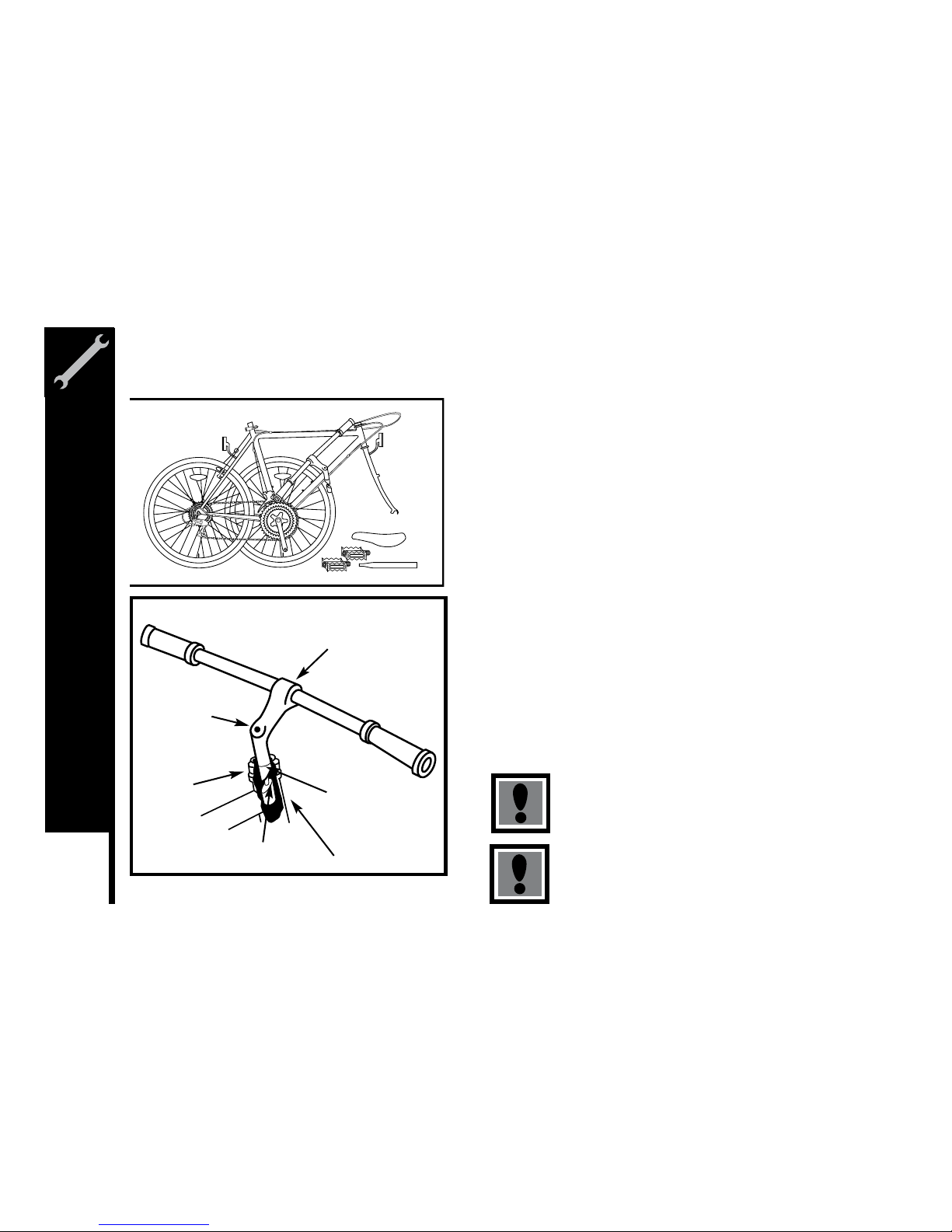
accessories and parts for possible shortages. It is recommended that the
threads and all moving parts be lubricated prior to installation. Do not
discard packing materials until assembly is complete to insure that no
required parts are accidentally discarded. Assemble your bicycle following
the steps that pertain to your model. NOTE: Your bicycle may be equipped
with different style components than the ones illustrated.
Handlebars
Remove the protective cap from the handlebar stem wedge and loosen
the Allen key bolt using the 6mm Allen key. Some models may use a
13mm hexagonal bolt instead of an Allen key bolt. Place the handlebar
stem into the top of the head tube, ensuring that all cables are free of
tangles. Tighten the stem bolt observing the minimum insertion mark and
checking that the forks and the handlebars are facing forward. Check the
headset for smooth rotation and the top nut is secured tightly. Loosen the
6mm Binder Bolt and rotate the handlebar. Retighten the Binder Bolt to
ensure the handlebar does not rotate in the stem. NOTE: Some bicycles
may be equipped with a stem that has an adjustable angle. In addition
to the normal assembly, these stems will require angling the stem to the
desired position, and securely tightening the 6mm angle bolt located in
the front of the stem bolt. Failure to do this may cause loss of steering
control.
Warning: Over-tightening the stem bolt or the headset
assembly may cause damage to the bicycle and/or injury
to the rider.
Minimum Insertion
Mark
Stem Wedge Bolt
Head Tube
Handlebar Binder Bolt
Top Nut
Wedge
The stem must be inserted so that the minimum insertion
mark cannot be seen.
24
ASSEMBLY
Meijer.com
Page 28
25
ASSEMBLY
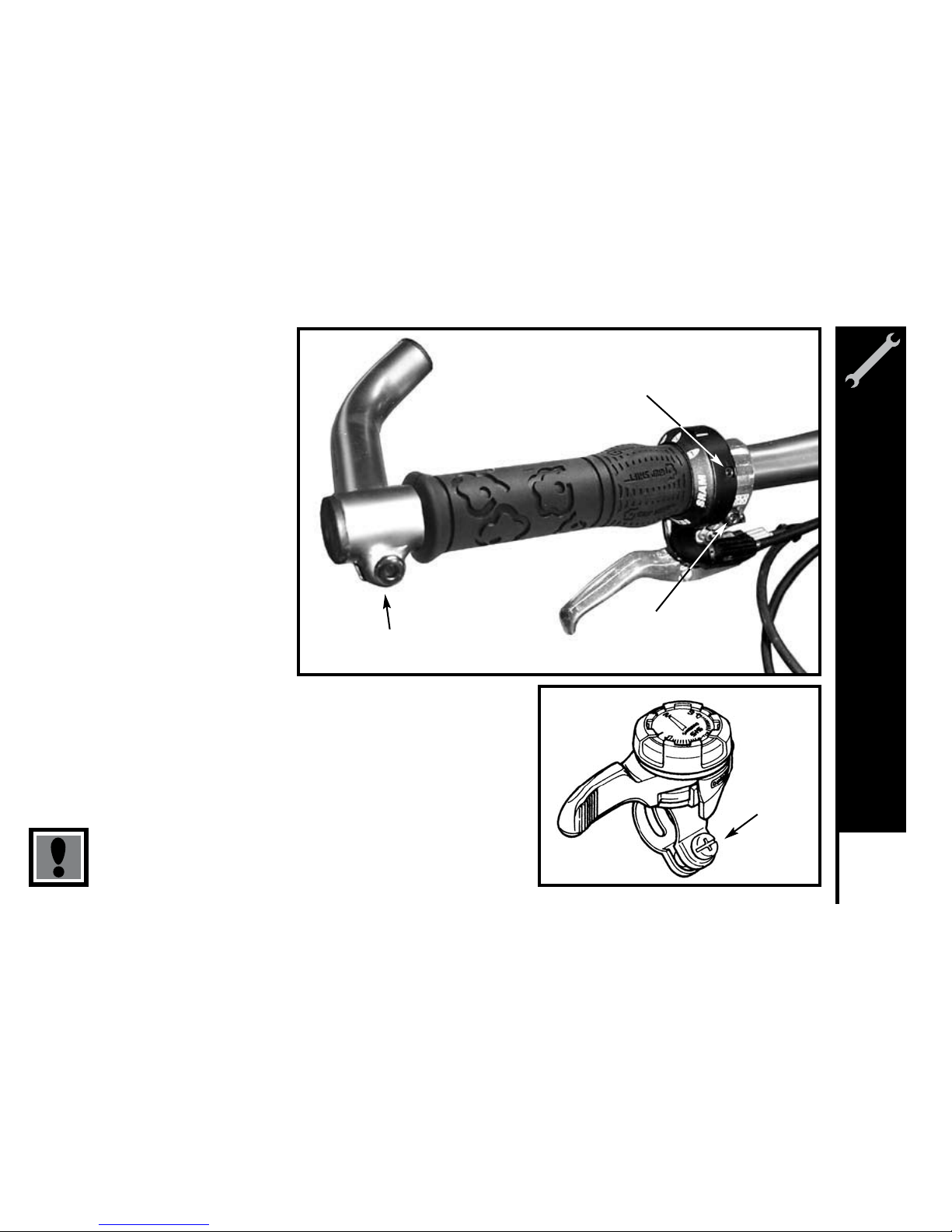
Tighten all bolts that clamp the shifters, brakes levers, and bar end to the handlebar
using a 5mm Allen key or Phillips head screwdriver.
(Figure 1) Handlebar with Twist Shifter.
(Figure 2) Top mounted thumb shifter.
Failure to properly tighten clamping bolts may cause sudden
movement of the component resulting in loss of steering control.
1.
Bar end (5mm Allen key)
Shifter binder bolt
(2.5 Allen key)
Brake lever binder bolt
(5mm Allen key)
2.
Shift binder
bolt (Phillips
head or 5mm
Allen key)
Meijer.com
Page 29
26
ASSEMBLY
Forks
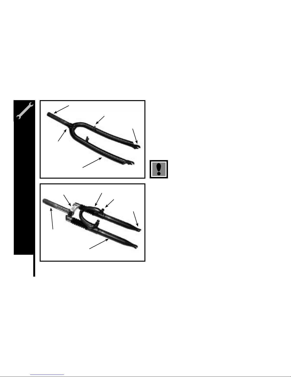
There are two different types of forks that range in styles and dimensions.
One type is a rigid fork (Figure 1) consisting of stationary tubing with
curved blades. The other type is a suspension fork (Figure 2) consisting
of stanchion tubes riding on elastomers or springs inside of a straight fork
leg. This mechanism acts as a shock absorber with a specified amount
of travel that varies between models. Some suspension forks are not
adjustable and are very difficult to disassemble. If service is needed on a
suspension fork, consult a professional bicycle repair technician.
Do not attempt to disassemble a suspension fork yourself.
Consult a professional bicycle repair technician.
Check the tightness of the headset and the fork. Rotate the fork checking
for smoothness. If it feels like the fork is binding, then an adjustment will
need to be made to the headset. Move the fork in a push/pull manner
checking for tightness. If any play is detected, loosen the top nut,
adjust the bearing cup, and retighten the top nut. Recheck the rotation
and tightness. If necessary, readjust until a smooth rotation is achieved
without backward or forward movement. If your bike is equipped with a
suspension fork, check that the fork compresses and rebounds smoothly.
To do this, place the fork dropouts against the ground, push and release
the handlebar. The fork will generally compress 1-2” and rebound quickly.
Most elastomer type forks will gradually soften with use.
Steering Tube
Crown
Brake Boss
Blade
Drop-out
1.
Steering Tube
Brake Boss
Fork Blade
Drop-out
Brake Bridge
Crown
2.
Meijer.com
Page 30
27
ASSEMBLY
Seat and Seat Post
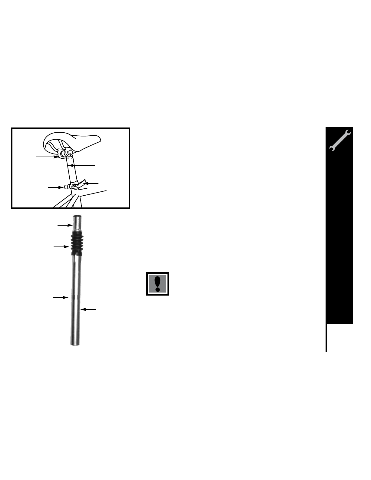
Attach the seat to the seat post by inserting the smaller end of the seat post
into the seat clamp and tighten. Insert the larger end of the seat post into
the seat tube of the bicycle frame observing the minimum insertion mark on
the seat post. Turn the adjusting nut of the Quick Release seat bolt to ensure
the locking lever is moved to the closed position with a firm action. Turn the
bicycle upside down and rest in on the seat and handlebars.
NOTE: Comfort bicycles may be equipped with a suspension seat post (See
Diagram-bottom left). Some suspension posts can be adjusted for stiffness
using the preload adjusting screw. Turning the 6mm Allen screw Clockwise
will decrease travel and make the suspension stiffer, while turning the
6mm Allen screw Counter-clockwise will increase travel and make the
suspension less rigid.
Note: In addition to normal assembly, please be aware that the preload
adjusting screw must be flush with the bottom of the post.
Failure to do this may cause irreparable damage.
The seat post must be inserted so that the minimum
insertion mark cannot be seen. The quick release
mechanism must be tightened securely to prevent a sudden
shift of the seat when riding Failure to do this may cause
loss of bicycle control.
Seat
Clamp
Seat
Post
Quick
Release
Adjusting
Nut
Attach
Seat Here
Boot
Minimum
Insertion
Mark
Insert this
end into
frame
Meijer.com
Page 31
28
ASSEMBLY
Pedals & Crank Set
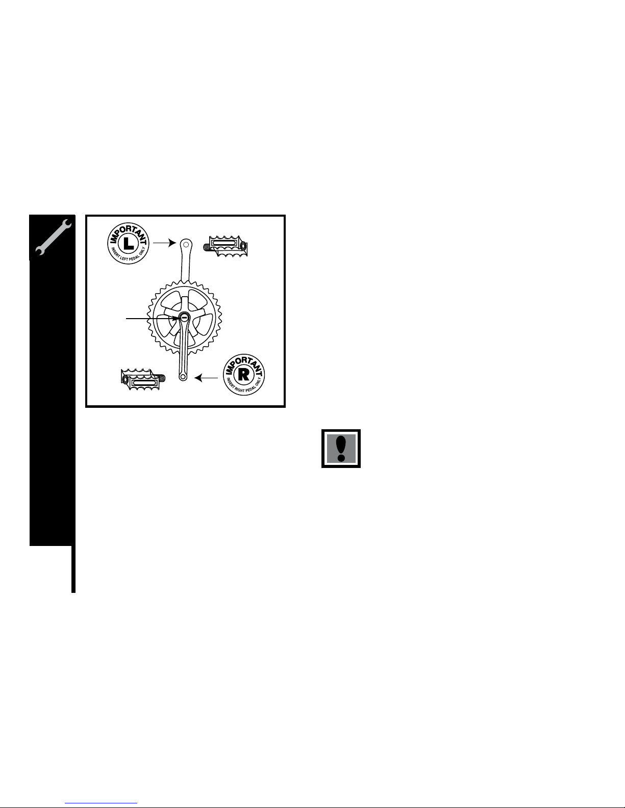
Look for the letters “R” for right, and “L” for left, stamped on each pedal
spindle. Start each pedal spindle by hand to avoid stripping the threads.
Tighten with a 15mm narrow open-ended wrench. Note that the right
hand pedal attaches to the chainwheel side crank arm with a right-hand
(clockwise) thread. The left pedal attaches to the other crank arm and
has a left-hand (counter-clockwise) thread. It is very important that you
check the crank set for correct adjustment and tightness before riding your
bicycle. New cranks may become loose with initial use; refer to p. 82-85
for proper crank set adjustment and maintenance. Once the pedals have
been installed, remove the dust caps from the center of each crank arm.
Using a 14mm socket wrench, tighten the spindle nuts securely (approx.
350 in. lbs) and replace the dust caps.
Attachment of an incorrect pedal into a crank arm will
cause irreplaceable damage.
Dust
Cap
Meijer.com
Page 32
29
ASSEMBLY
Front Wheel
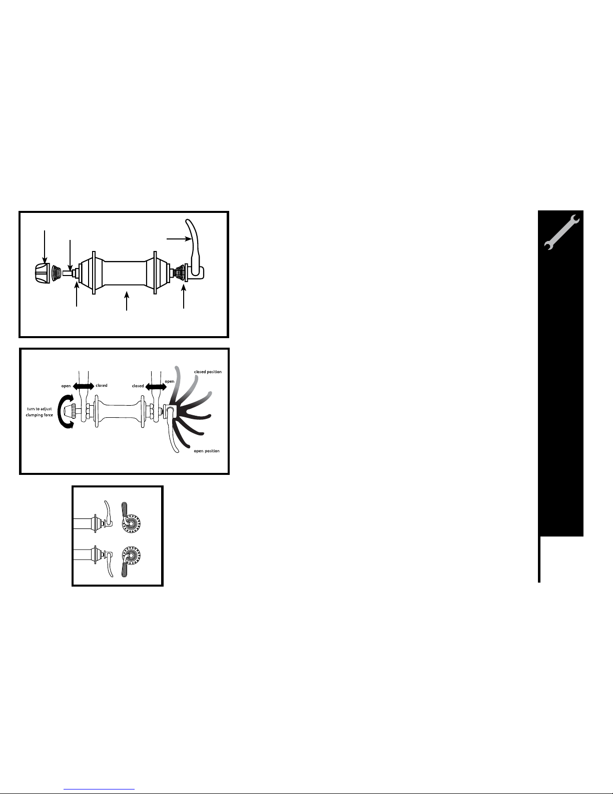
Check the wheel hub before attaching in to the fork by rotating the threaded
axle. It should be smooth with no lateral movement. Insert the front wheel
into the fork dropouts. Tighten the wheel nuts using the appropriate 14mm
or 15mm wrench. Spin the wheel nuts using the appropriate 14mm or 15mm
wrench. Spin the wheel checking for trueness. Some bicycles have quick
release wheel axles, turn the adjusting nut so the locking lever is moved to the
closed position with a firm action. At the halfway closed position of the quick
release lever, you should start to feel some resistance to this motion. If the
quick release lever is moved to the closed position with no resistance,
clamping strength is insufficient. Move the quick release lever to the open
position, tighten the quick release adjusting nut, and return the quick release
lever to the closed position.
Correct Quick Release Axle Setting
1. Place bike upside down, resting on the seat and handlebars.
2. To set, turn the lever to the open position so that the curved part faces
away from the bicycle.
3. While holding the lever in one hand, tighten the adjusting nut until it
stops.
4. Pivot the lever towards the closed position. When the lever is halfway
closed, there must be firm resistance to turn it beyond that point. If
resistance is not firm, open the lever and tighten the adjusting nut in a
clockwise direction.
5. Continue to pivot the lever all the way to the closed position so that the
Hub
Hub
Axle
Quick Release
Axle
Adjusting
Nut
Quick
Release
Lever
Spring
Closed Position
Open Position
Meijer.com
Page 33
30
ASSEMBLY
Front Brake
Determine which type of brake your bike is equipped with and refer to
the appropriate assembly instructions. For more information on brake
adjustment and maintenance.
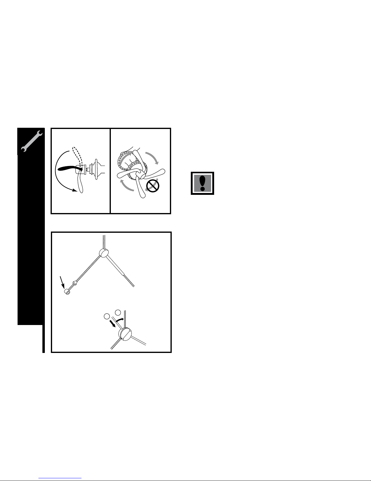
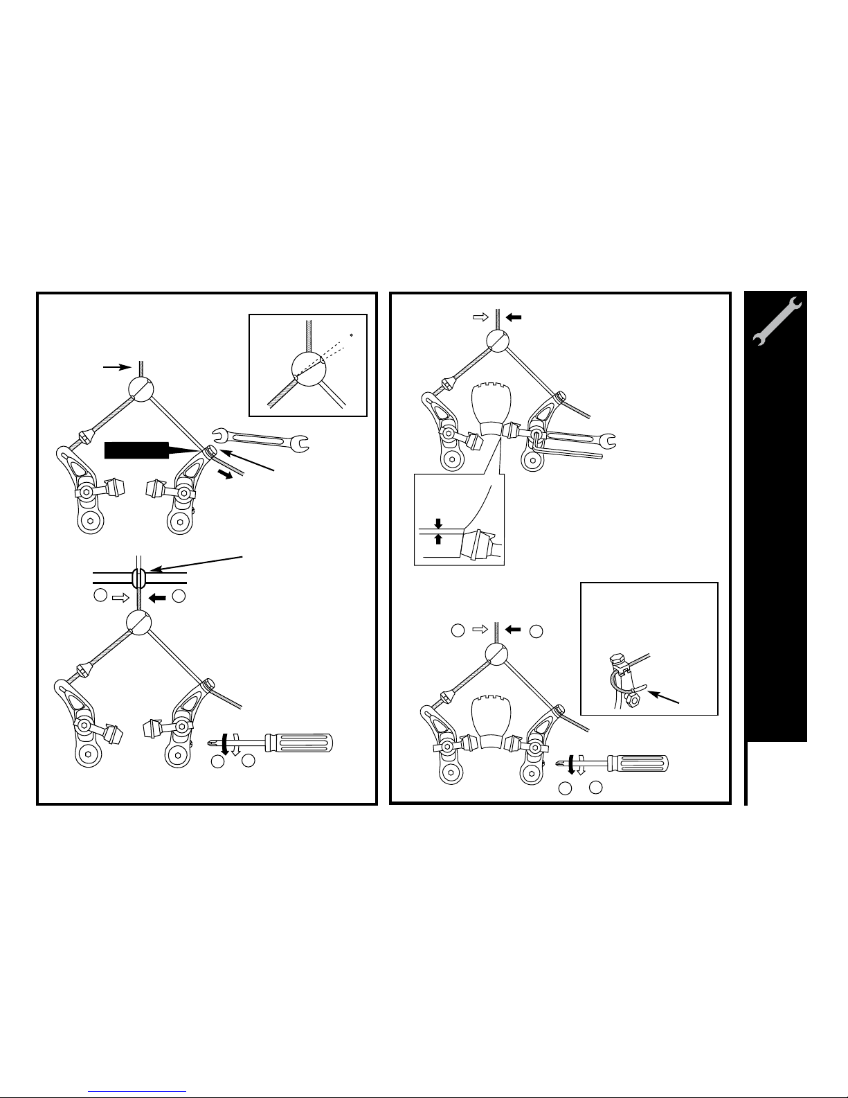
Cantilever Brakes – Link Wire
If fitted with cantilever type brakes, insert the brake cable into the link wire
lead, and notch the cable end into the slot of the left brake cable under the
tabbed washer. Squeeze both brake arms together so the brake shoes hit
the rim, pull all slack out of the brake cable, and tighten the anchor bolt.
With the cable fitted, the straddle holder should sit 10 – 20mm above the
reflector bracket. Adjust the brake shoes using a 10mm wrench so that
they are parallel with the rim and are positioned 1-2mm away from the
rim. Several adjustments may be necessary to achieve the correct brake
position.
curved part of the lever faces the bicycle.
5. The wheel is tightly secured when the serrated surfaces of the quick
release clamping parts actually begin to cut into the bicycle frame/fork
surfaces.
6. Note that the same procedure applies when operating a quick release
seat post binder mechanism.
Warning – Correct adjustment of the quick release is
vitally important to avoid an accident caused by loose
wheel.
1. Install the cable into
the link wire.
2. Set the cable into
the straddle holder.
1
2
Cantilever
Brakes
Cable
End
Meijer.com
Page 34
31
ASSEMBLY
3
3. Temporarily tighten the cable so
that the link wire is at the position in
the illustration.
1
2
1
2
5. Secure one of the shoes at a time.
The adjustment of the shoe clearance is
not necessary at this time.
Shoe fixing nut tightening torque:
7.84 - 8.82 Nm (70 - 78 in. lbs.)
1 mm
10 mm wrench
5 mm Allen key
Cable Anchor Bolt
To uc hi ng
End cap
Cut off any unnecessary
cable, attach an end cap,
and hook it onto the
notched part of the nut
which secures the shoe.
Cable Casing Holder
Link Wire
Meijer.com
Page 35
32
ASSEMBLY
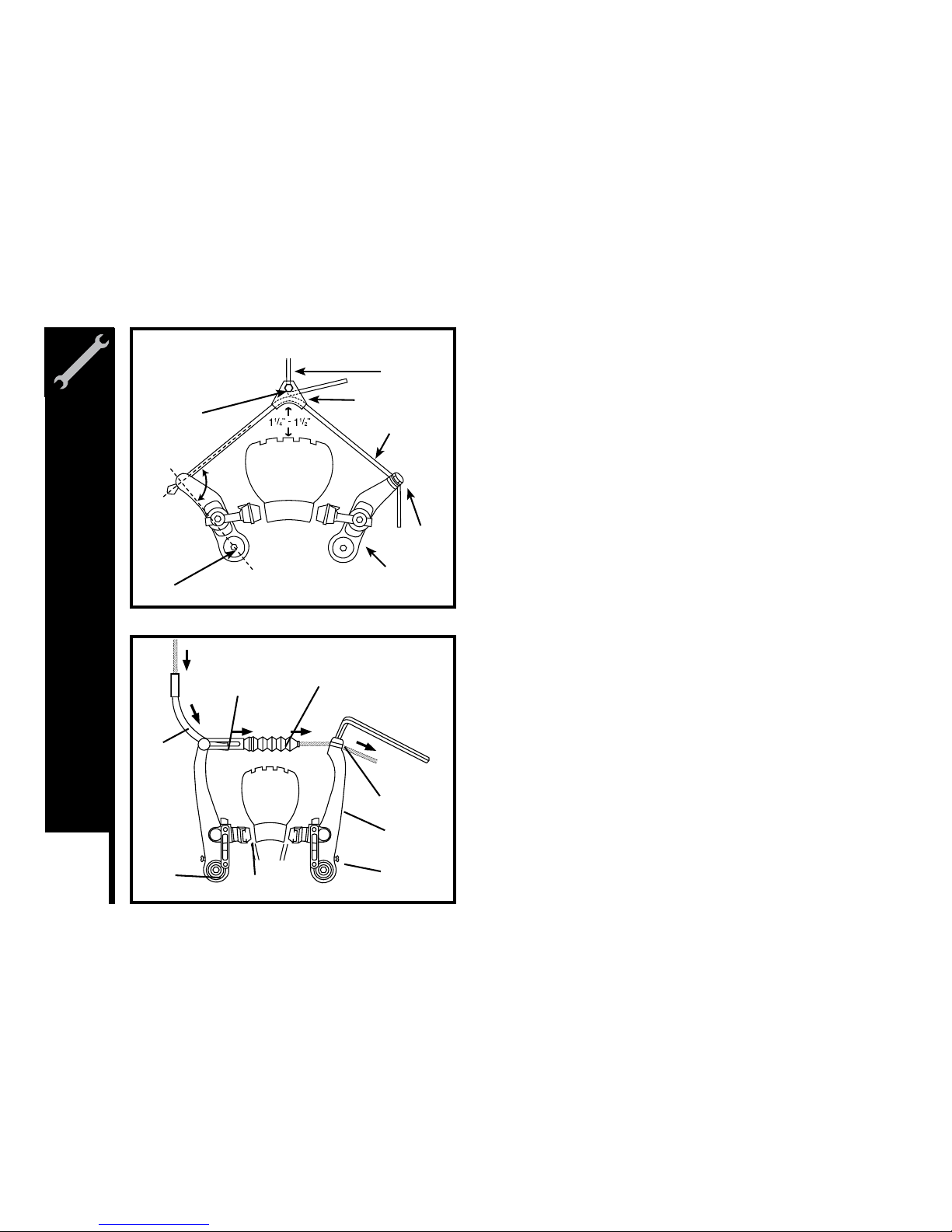
Cantilever Brakes – Straddle Cable
The length of the straddle cable, the height of the straddle hanger and
the brake pad-to-caliper arm position all have an effect on braking
power. Generally, the straddle cable should be high enough, however,
to adequately clear the tire (and any debris that may stick to the tire) or
to fit over the front reflector hanger. The straddle cable length (when
adjustable) is set to transfer as much force to the brake pads as possible.
For the most efficient transfer of force, the straddle cable and the line
between the cantilever pivot and the cable anchor should form a right
angle (90 degrees). If the force is not at a right angle, part of the force
gets wasted in pulling on the brake post, which has no effect on braking.
V-Style Brakes
Take the brake noodle from the parts box and slide the cable through
the larger opening. The cable housing will then seat into the end of the
noodle. Slide the cable through the cable lead on the end of the left brake
arm, this will cause the noodle to fit into the lead. Slip the brake cable
boot over the cable and position it between both brake arms. Next, loosen
the 5mm anchor bolt at the end of the right brake arm and slide the cable
under the retaining washer. Pull the slack out of the cable making sure
a distance of 39mm or more remains between the end of the lead and
the start of the anchor bolt. Once the cable is secured to the brake arms,
engage the brake lever several times, checking the position of the brake
shoes at the rim. The brake shoes should be 1mm away from the rim
when in a relaxed position. When the brake lever is engaged, the brake
shoe should hit the rim flush (never the tire) with the front touching slightly
before the rear. If this position is not achieved, adjustments to the brake
shoe are required. Loosen the brake shoe hardware and reposition the
brake shoe. It may take several shoe and cable adjustments before the
required position is accomplished.
Straddle
Cable
Brake
Brake Cable
Straddle Hanger
Straddle Cable
Cable
Anchor
Caliper Arm
Pinch Bolt
Pivot
90
o
Brake
Noodle
Outer
Cable
Lead
Brake
Cable
Boot
Anchor
Bolt
Brake
Arm
Tension
Screw
Brake
Shoe
Pivot
Bolt
Meijer.com
Page 36
33
ASSEMBLY
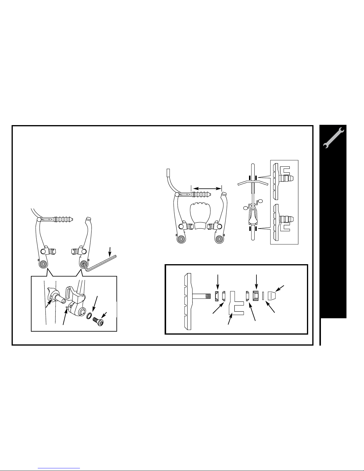
V - Brake
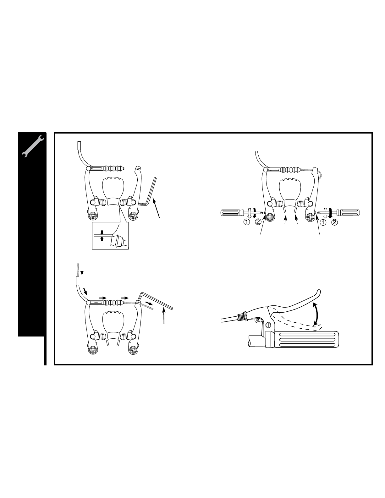
If fitted with V-Brakes, insert the brake body into
the center spring hole in the frame mounting
boss, and then secure the brake body to the
frame with the link fixing bolt.
1.
While holding the shoe against the rim, adjust the
amount of shoe protrusion by interchanging the
position of the B washers (i.e. 6 mm and 3 mm) so that
dimension A is kept at 39 mm or more.
2.
5 mm Allen key
Washer
Link
fixing
bolt
Stopper pin
Spring
hole
39 mm or more
A
3 mm washer B 6 mm washer B
Washer A
Shoe fixing link
Washer A
Washer
Shoe fixing nut
Meijer.com
Page 37
34
ASSEMBLY
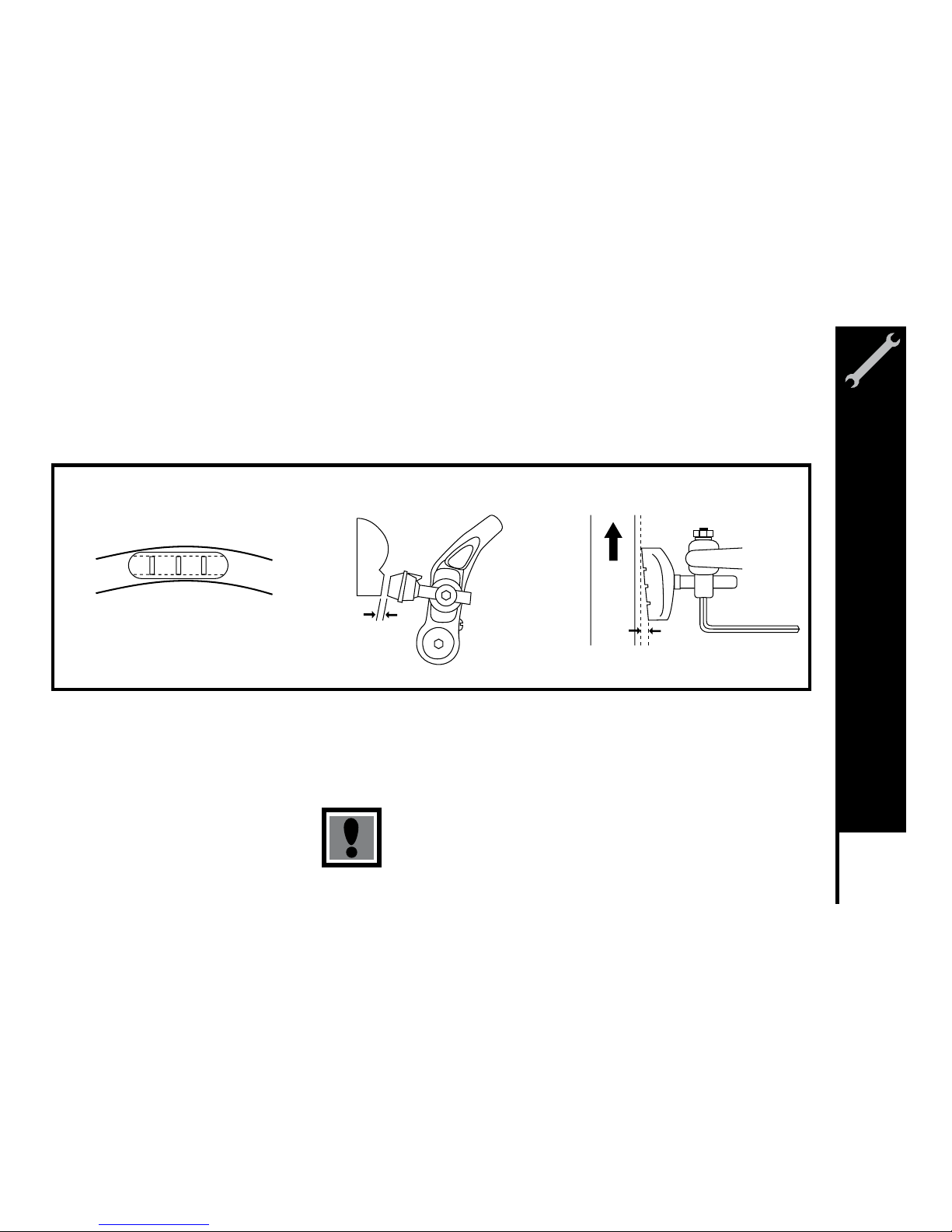
While holding the shoe against the
rim, tighten the shoe fixing nut.
3.
Adjust the balance with the spring
tension adjustment screws.
5.
Depress the brake lever about 10 times as
far as the grip to check that everything is
operating correctly and that the shoe
clearance is correct before using the brakes.
6.
Pass the inner cable through the inner
cable lead. Set the cable with a clearance
of 1mm between each brake pad and the
rim, tighten the cable fixing bolt.
4.
5 mm Allen key
5 mm Allen key
1mm 1mm
1 mm
Spring tension
adjustment screw
Spring tension
adjustment screw
Depress about
10 times
1 mm 1 mm
shoe fixing nut
Meijer.com
Page 38
35
ASSEMBLY
Check your Brakes
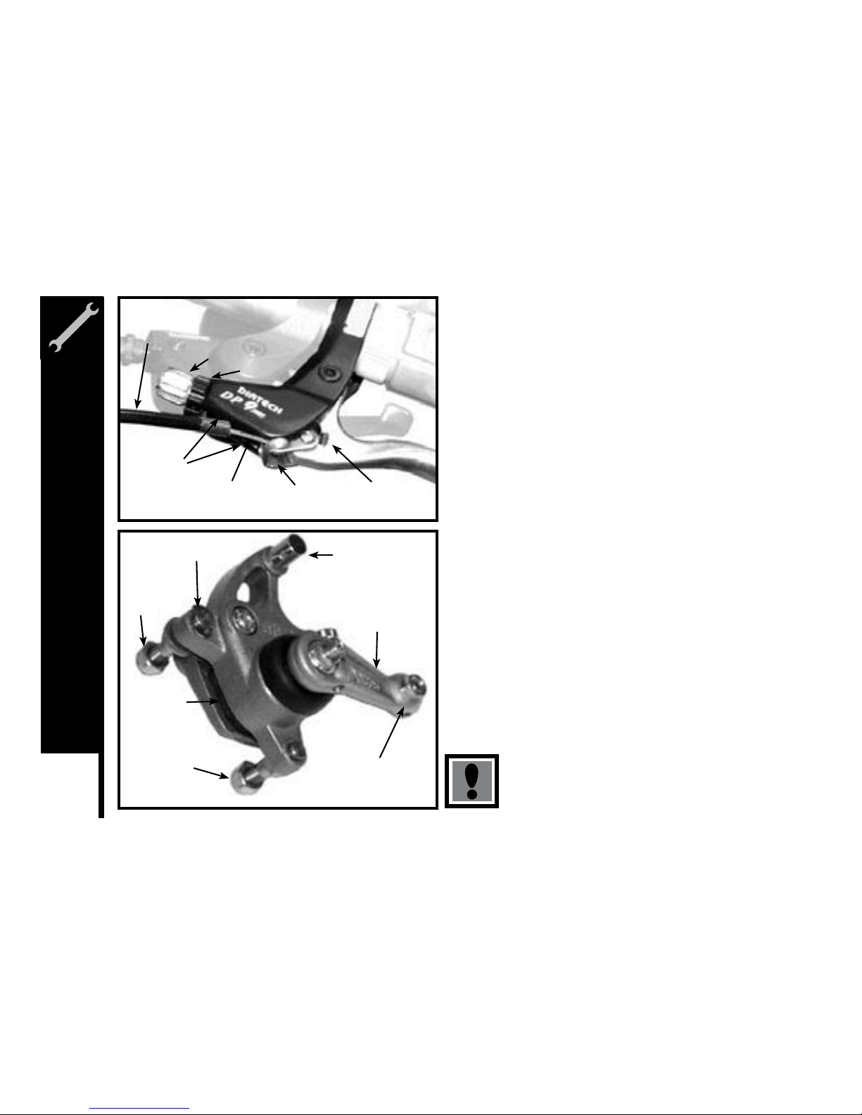
Press each brake lever to make sure that there is no binding and that the brake pads press hard enough on the rims to stop the bike.
The brake pads should be adjusted so they are 1mm to 2mm away from the rim when the brakes are not applied. Brake pads should
be centered on the rim and the rear portion of each brake pad should be about 0.5 – 1.0mm farther from the rim than the front portion
of the brake pad.
Do not ride the bicycle until the brakes are functioning properly.
To test, apply the brakes while trying to push the bike forward to
make sure they will stop the bicycle.
Brake pad aligned with the rim surface Pad and rim should be parallel.
Direction of rim
rotation
0.5 - 1.0 mm
1- 2 mm
Meijer.com
Page 39
36
ASSEMBLY
Disk Brakes
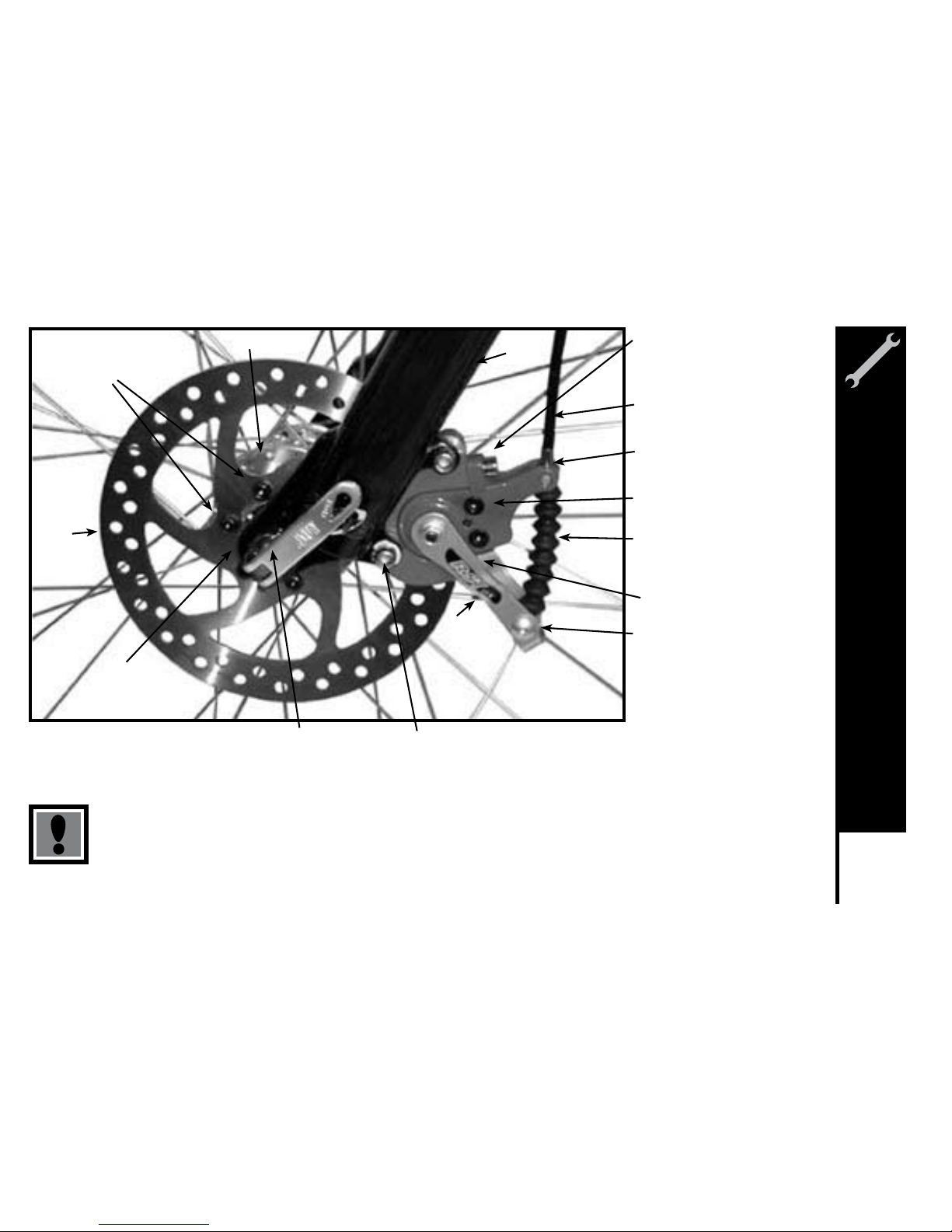
If fitted with a front disc brake, the components should already be
attached. However, please check all connections before attempting to ride
the bicycle. Secure tightly the 6 bolts that hold the disc to the front wheel
hub and the 2 bolts that hold the brake mechanism to the fork. Insert the
front rim into the fork dropouts ensuring that the disc fits into the brake
mechanism between the enclosed brake pads. Secure the front rim to the
bicycle by tightening the quick release mechanism and clamping the lever
to the closed position.
Next, attach the cable to the brake lever by inserting the cable end into
the cable end holder after the barrel adjuster and lock nut slots have
been aligned with the cable end holder. After the cable is secured to the
lever, rotate the barrel adjuster and lock nut so the slots no longer line up.
Ensure the cable housing seats appropriately into the end of the barrel
adjuster and check for any kinks or damage.
Slide the exposed brake cable through the rotating rod located on the
caliper body and seat the housing into the same stop. Insert the cable into
spring and spring boot.
Next, slide the cable through the cable anchor and pull all the slack out.
Secure the cable in place by tightening the bolts that comprise the anchor
assembly. Some disc brakes will have a centering device while others are
a free-floating mechanism. If your caliper body is equipped with centering
bolts, apply the brake lever after the cable has been connected. While
engaging the lever, tighten the centering bolts securely. This will center the
caliper body on the disc.
DISC GETS HOT! Severe injury could result from contact
with the hot disc! Mind your legs, as well as your hands.
Barrel Adjuster
Brake Cable
Housing
Cable
Insertion
Slot
Brake Cable Cable End
Holder
Brake Type
Selector
Brake Lever
Lock Nut
Brake Pads
C Clip
Actuating Arm
Rotating Rod
Cable Anchor
Bolt
Caliper
Mounting
Bolt with
spacers
Caliper
Mounting
Bolt with
spacers
Meijer.com
Page 40
37
ASSEMBLY
These brakes require breaking in! Ride and use the brakes gently for 13 miles before
using the brakes in downhill conditions, for sudden stops, or any other serious braking.
Please be aware that your brake system will change in performance throughout the
wear-in process. The disc brake should be cleaned before the first ride using rubbing
alcohol. NEVER use oil or similar products to clean your disc brake system.
Fork Leg
Brake Cable
Housing
Rotating
Rod
Cable Boot
with Spring
inside
Cable Anchor
Bolt
Caliper
Body
Actuating
Arm
Caliper Mounting
Bolts with spacers
Quick Release
lever
Fork Drop Out
Disc
Disc Mounting
Bolts
Hub
Centering Bolt
Centering Bolt (inside)
Meijer.com
Page 41
38
ASSEMBLY
DERAILLEUR
Although the front and rear derailleurs are initially adjusted at the factory,
you will need to inspect and readjust both prior to riding the bicycle.
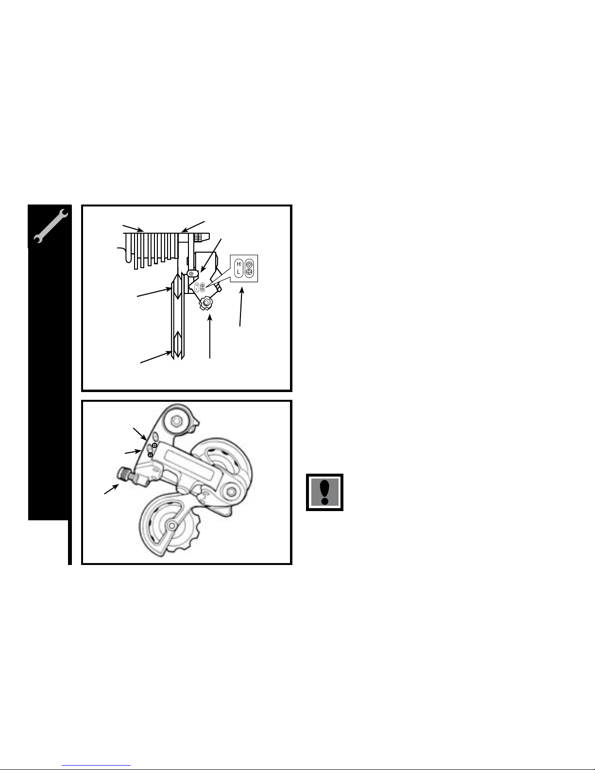
Rear Derailleur
Begin by shifting the rear shifter to largest number indicated, disconnect
the cable from the rear derailleur cable anchor bolt, and place the chain
on the smallest sprocket.
Adjust the High limit screw so the guide pulley and the smallest sprocket
are lined up vertically. Reconnect the cable, pull out any slack, and
retighten the anchor bolt securely. Shift through the gears, making sure
each gear achieved is done quietly and without hesitation. If necessary,
use the barrel adjuster to fine-tune each gear by turning it the direction
you want to chain to go. For example, turning counter-clockwise will
tighten cable tension and direct the chain towards the wheel. Shift the
rear shifter to the gear one and place the chain on the largest cog. Adjust
the Low limit screw in quarter turn increments until the guide pulley and
the largest cog are aligned vertically. Again, shift through each gear
several times, checking that each gear is achieved smoothly. It may take
several attempts before the rear derailleur and cable is adjusted properly.
Ensure all bolts are secured tightly and the chain does
not fall off in either direction.
Guide Pulley
Cable Adjuster
Adjustment
Screws
Freewheel Outer side of Top Gear
Pulley Adjustment
Screw
Tension Pulley
High Gear
Adjustment Screw
Low Gear
Adjustment
Screw
Barrel
Adjuster
Rear Derailleur Side View
H
L
Meijer.com
Page 42
39
ASSEMBLY
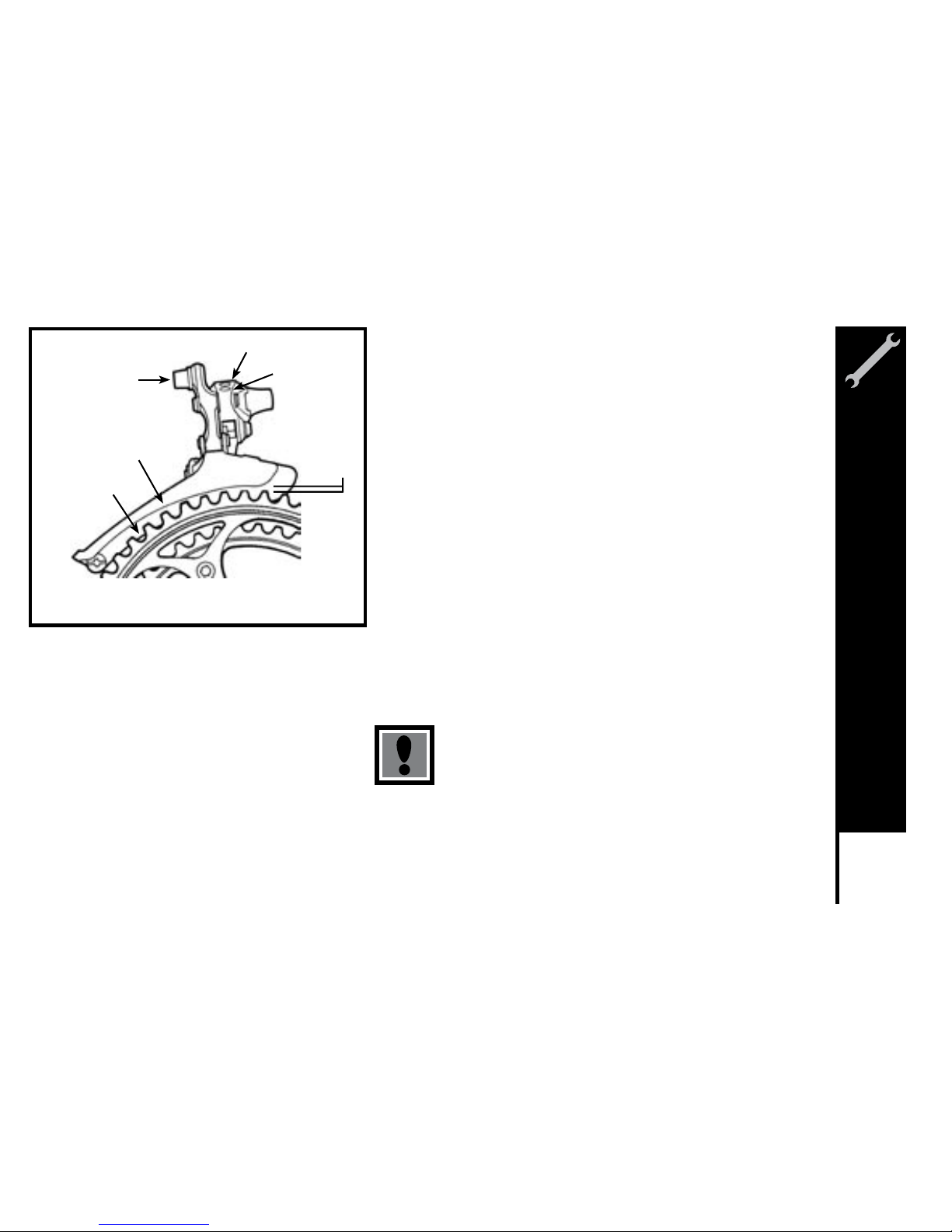
Front Derailleur
Shift both shifters to the smallest number indicated and place the chain
on the corresponding cog and chainwheel. Disconnect the front derailleur
cable from the cable anchor bolt. Check the position of the front derailleur; it
should be parallel with the outer chainwheel and clear the largest chainwheel
by 3-5mm when fully engaged.
With the chain on the smallest chainwheel in front and the largest cog
in back, adjust the Low limit screw so the chain is centered in the front
derailleur cage. Reconnect the cable, pull any slack out, and tighten the
anchor bolt securely. Shift the front shifter to the largest chainwheel. If the
chain does not go onto the largest chainwheel, turn the high limit screw in
1/4 turn increments counter-clockwise until the chain engages the largest
chainwheel. If the chain falls off the largest chainwheel, and into the pedals,
you will need to turn the High limit screw in 1/4 turn increments clockwise
until the chain no longer falls off. Shift through every gear, using the barrel
adjusters to fine-tune each transition. The barrel adjuster for the front
derailleur is located on the front shifter where the cable comes out of the
shifter. Clockwise will loosen the cable tension and direct the chain closer to
the frame while counter-clockwise will tighten the cable tension and direct
the chain away from the frame.
Do not ride a bicycle that not shifting properly.
Overlooking proper adjustments may cause irreparable
damage to the bicycle and/or bodily injury.
Low Adjusting Screw
Cable Anchor Bolt
Outer Chainguide
Inner Chainguard
High Adjusting
Screw
Chainguide
clearance of
1-3mm
Meijer.com
Page 43
40
ASSEMBLY
Dual Suspension
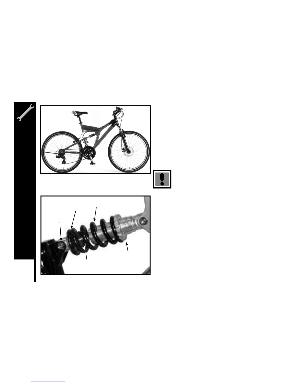
Dual suspension bikes are equipped with a front fork as well as a
rear suspension generally located below the seat. The piston works
in conjunction with a spring to allow the bike to rotate on a pivot point.
Ensure all attaching hardware is secured and there is no lateral movement
of the rear triangle. The amount of rear suspension travel can be
adjusted by turning the adjustment plate. By turning the adjustment plate
clockwise, you will increase spring tension and decrease travel, while
turning counter-clockwise you will decrease spring tension and increase
travel.
There must be enough tension on the spring to hold
the spring in place. Failure to do this may cause the
mechanism to fail.
Anchor bolt
Spring plate
Spring
Piston
Adjusting plate
Meijer.com
Page 44
41
ASSEMBLY
Rear Pivots
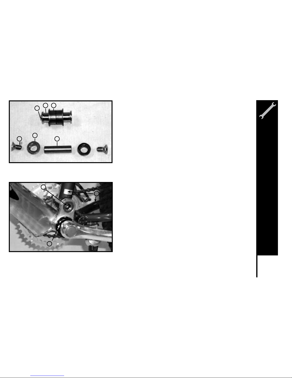
The pivots assembly is a simple mechanism that allows the rear triangle to
move up and down in combination with a rear suspension. Size, shape,
and compounds will vary between models; however, operating principles
are the same. A shaft will pivot inside of two bushings secured in place
with bolts. Pivots should be kept clean and free from grime and should be
disassembled and regreased at least once a riding season. Please note the
drive side crank arm must be removed from the spindle before attempting
to work on the pivot. Some models have two small (2.5mm) Allen bolts on
the underside of the bottom bracket shell. These must be removed before
attempting to disassemble the pivot. After disassembling and cleaning,
the shaft of the pivot assembly should be lightly coated with lithium-based
grease, as well as the bushings and the threads of the attaching hardware.
Please remember: Never use WD-40 to grease components. It is a
degreaser that will not provide required lubrication and has a tendency to
attract dust.
1. Pivot Assembly
2. Bottom Bracket Cup & Lockring
3. Rear Triangle
1
1
2
2
3
3
1.Attaching Bolt
2.Bushing
3.Shaft
1
2
3
Meijer.com
Page 45
42
ASSEMBLY
Accessories
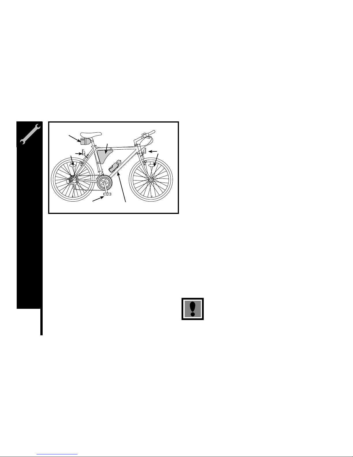
If your bike is supplied with a water bottle and cage, attach the cage to the
bicycle using the Allen bolts provided.
Some bikes come equipped with a saddlebag or frame bag. The
saddlebag installs under the seat with the zipper facing the rear wheel.
Undo the straps that wrap around the bag, thread them through the rails
underneath the seat and secure around the bag. The smaller strap wraps
around the seat post. Frame bags install at the apex of the top and seat
tubes. Secure the straps around each tube.
NOTE: The frame bag straps must not bind the cables. The straps must
go around the frame only.
Other: Some 20” and 24” model bicycles come with a rear derailleur guard
to protect the rear derailleur from damage. To install, remove the rear
wheel axle nut on the drive side, install the rear derailleur guard over the
axle with the U-shaped guard pointing down, and retighten the axle nut.
The guard will sit between the frame and the axle nut.
If provided with a handlebar mounted reflector, this reflector must be
mounted as close to the center of the handlebar as possible.
Reflectors
Attach the white reflector to the front reflector bracket and secure to the
handlebar or fork using the hardware provided. Attach the red reflector to
the rear reflector bracket and secure to the frame or seat post, depending
on the bracket style, with the hardware provided.
Tighten both rear wheel axle nuts and the quick release
mechanism securely. Failure to do this may cause the
rear wheel to dislodge from the frame dropouts resulting
in serious damage or injury.
Saddle Bag
Frame Bag
Reflector
Reflector
Reflector
Water bottle and cage
Meijer.com
Page 46
43
ASSEMBLY
Final Check
After all adjustments have been made, shift through every gear several times at
varying speeds. This will ensure all your adjustments are correct and will allow
you to pinpoint any trouble areas. If you encounter any problems, refer to the
appropriate section and make any necessary adjustments.
Check the tire pressure and inflate each tube to the recommended psi as
stated on the sidewall of the tire.
Check that the kickstand operates smoothly and the kickstand bolt is secured
tightly.
Finally, examine the bicycle. Make sure all accessories are attached and all
quick releases, nuts and bolts have been tightened securely.
Correct maintenance of your bicycle will ensure many years of happy riding.
Service your bicycle regularly by referring to the relevant sections of the
manual, OR take it to a professional bicycle shop.
Remember: Always wear helmet and obey all traffic laws.
Do not over-inflate the tires.
Meijer.com
Page 47
44
ASSEMBLY
Foreword: Assembling a bicycle is an important responsibility. Proper
assembly not only gives the rider more enjoyment of the bicycle; it also
offers an important measure of safety.
Getting Started
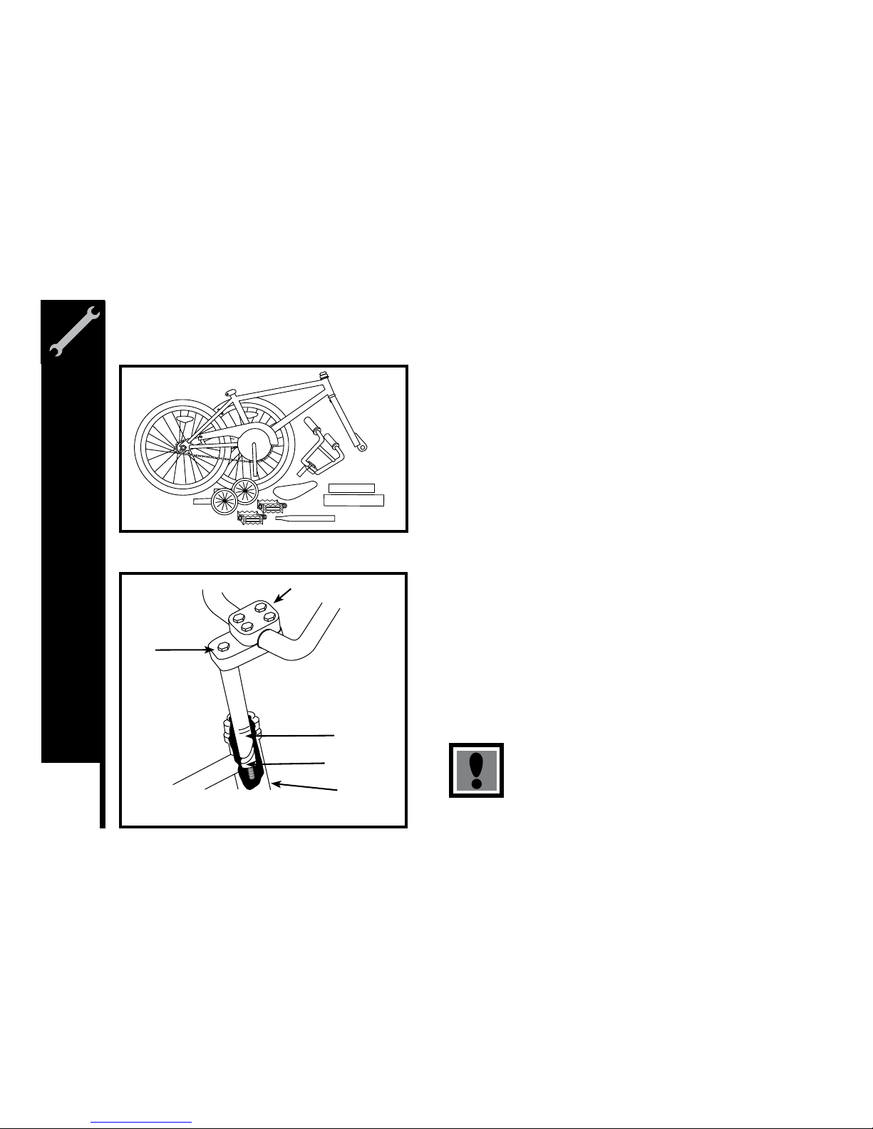
Open the carton from the top and remove the bicycle. Remove the straps
and protective wrapping from the bicycle. Inspect the bicycle and all
accessories and parts for possible shortages. It is recommended that
the threads and all moving parts in the package be lubricated prior to
installation.
Do not discard packing materials until assembly is complete to insure
that no required parts are accidentally discarded. Assemble your bicycle
following the steps that pertain to your model.
Note: Your bicycle may be equipped with different style components than
the one illustrated.
Handlebars
Remove the protective cap from the stem wedge and loosen the stem
bolt using the 6mm Allen key. Some models may use a 13mm hexagonal
bolt. Place the handlebar stem into the head tube, observing the minimum
insertion mark on the handlebar stem and ensuring that all cables are free
of tangles. Check that the fork and the handlebar are facing forward, and
that they are properly aligned with the front wheel. Tighten the stem bolt.
Rotate the handlebar to the desired position and tighten the Stem Cap
Binder Bolts securely using a 5mm Allen key.
SINGLE SPEED & BMX
Includes 16” and 20” BMX Bikes
Assembly is the same for boy and girl’s bikes.
The handlebar must be inserted so that the minimum
insertion mark cannot be seen. Warning: Over-tightening
the stem bolt or headset assembly may cause damage to
the bicycle and/or injury to the rider.
Stem
Bolt
Minimum
Insertion Mark
Head
Tube
Stem Cap Binder Bolts
Stem Wedge
Meijer.com
Page 48
45
ASSEMBLY
Seat
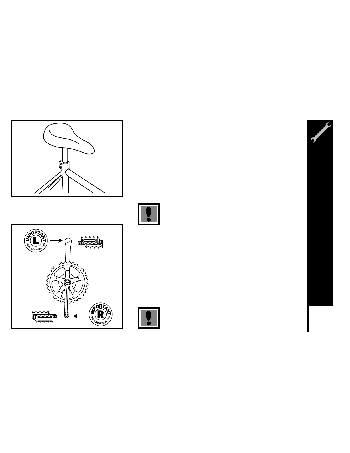
Loosen nut on the seat clamp and add 3 or 4 drops of oil onto the threads
of the bolt. Place the smaller end of the seat post into the seat clamp until
it stops with the bolt to the rear of the seat post. Thread the nut on the seat
clamp loosely. Insert the larger end of the seat post into the seat tube of
the bicycle frame observing the minimum insertion mark on the seat post.
Position the top surface of the seat parallel with the ground. The serrations
on the seat clamp must mesh completely with the seat frame serration.
Securely tighten the bolts on the seat post clamp. Turn the bicycle upside
down and rest it on the seat and handlebars. If your bicycle is equipped
equipped with a quick release mechanism, please refer to page 29-30.
The seat pillar must be inserted so that the minimum
insertion mark cannot be seen.
Pedals & Crank Set
Look for the letters “R” for right, and “L” for left, stamped on each pedal
spindle. Start each pedal spindle by hand to avoid stripping the threads.
Tighten with a 15mm narrow open-ended wrench. Note the right hand pedal
attaches to the chainwheel side crank arm with a right-hand (clockwise)
thread. The left pedal attaches to the other crank arm and has a left-hand
(counter-clockwise) thread. It is very important that you check the crank set
for correct adjustment and tightness before riding your bicycle. New cranks
may become loose with initial use; refer to p. 82-85 for proper crank set
adjustment and maintenance. Once the pedals have been attached, check
that the crank arm rotates smoothly and that there is no lateral movement.
Attachment of an incorrect pedal into a crank arm will
cause irreparable damage.
Meijer.com
Page 49
46
ASSEMBLY
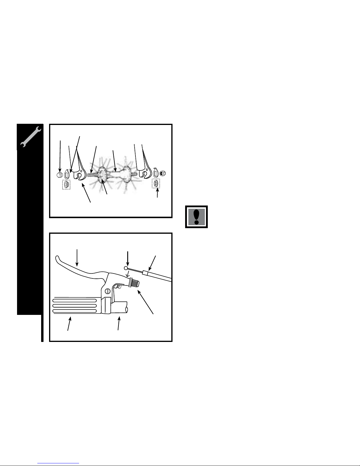
Front Wheel
1. Make sure the brakes are loose enough to allow the wheel to pass
through the brake pads easily.
2. Place wheel into fork drop outs
3. Install retaining washers with raised lip pointed towards the fork, and
insert into the small hole of the fork blade.
4. Install axle nut and tighten. Make sure the wheel is centered between
the fork blades.
5. Spin the wheel to make sure that it is centered and clears the brake
shoes. Tighten the brakes if necessary.
6. Turn the bicycle upright using the kickstand to support it.
It is very important to check the front wheel
connection to the bicycle. Failure to properly tighten
may cause the front wheel to dislodge.
Front Brake
Determine which type of brake your bike is equipped with and refer to
the appropriate assembly instructions. For more information on brake
adjustment and maintenance, refer to p. 30-36. A greater force is required
to activate the rear brake due to longer cable length. It is advisable to
mount the rear brake on the side of the stronger hand. It is important to
become familiar with the use of hand brakes. When properly adjusted,
hand brakes are an efficient brake system. Keep the rim and brake shoes
clean and free from wax, lubricant and dirt at all times. Keep brakes
properly adjusted and in good working condition at all times.
Open the brake lever and place the nipple end of the short brake cable
into the lever, than close the lever. Secure the ferrule against the lever
using the cable adjusting barrel.
Axle Nut
Axle
Hub
Cone Nuts
Fork Drop Out
Retaining
Washer
Step
Retaining
Washer
Brake Lever
Nipple
Ferrule
Grip Handlebar
Cable
Adjusting
Barrel
Meijer.com
Page 50
47
ASSEMBLY
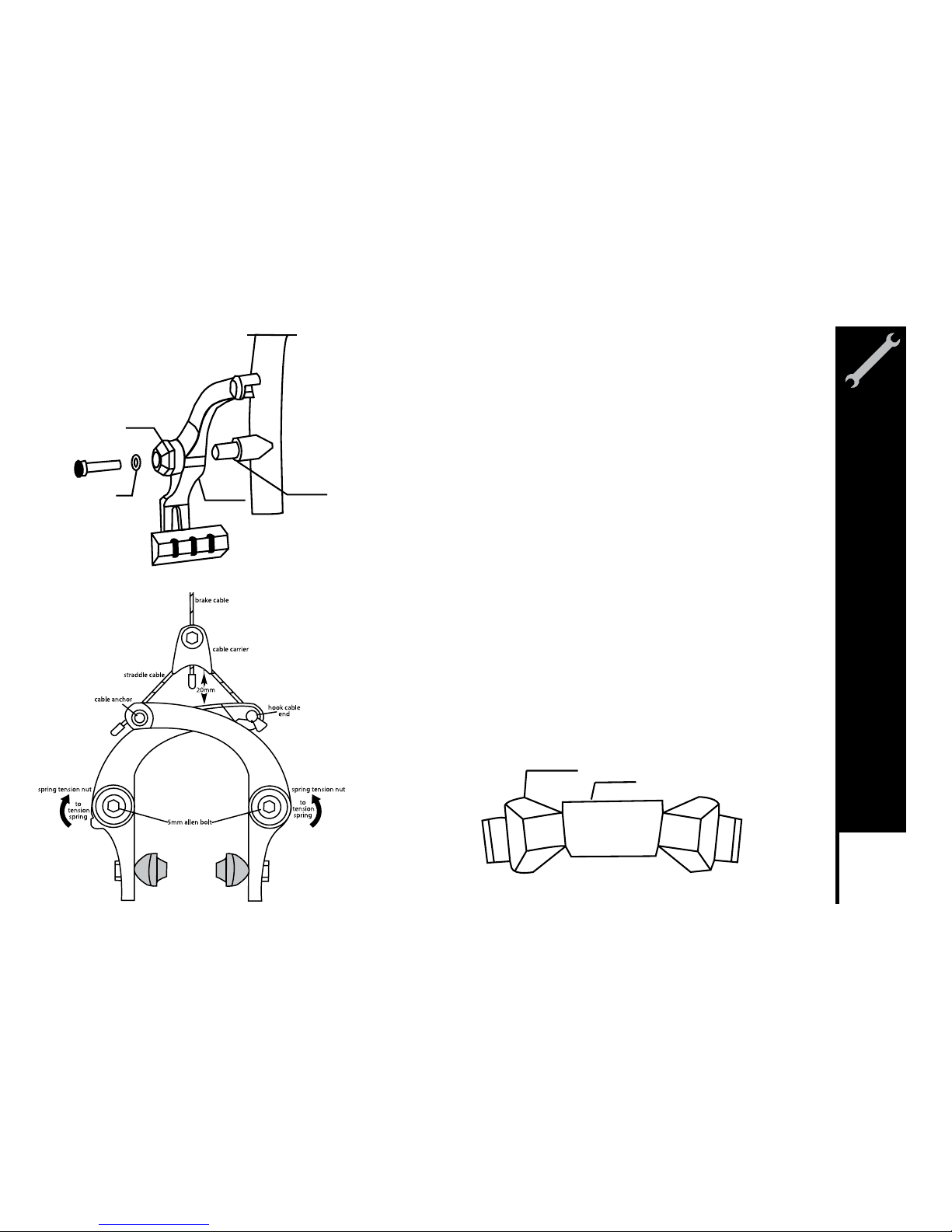
U-Brake
1. Install the left brake arm onto pivot on the frame, assemble washer (C)
and the inner hex fixing bolt(A) without fastening them tightly.
Repeat the same procedure to assemble the right arm.
2. Position the brake pads and make sure they match well with th rim.
3. Turn 90 degrees clockwise to fasten the tension adjuster waster (B)
with a 19mm wrench. Then fasten inner hex fixing bolt with a 5mm
allen key.
4. Repeat steps 2 and 3 to fix the right arm.
5. Loosen the anchor bolt, then install the cable into the cable anchor nut
and then slide the cable under the tabbed washer of anchor bolt.
6. Squeeze both brake arms together so the brake shoes hit the rim pull
all slack out of the brake cable, and lighten the anchor bolt.
7. Adjust the brake shoes using a 10mm wrench so that they are parallel
with the rim and are positioned 1-2mm away from the rim. Several
adjustments may be necessary to achieve the correct brake position.
Warning: Cut off any unnecessary calbe, attach an end cap, and hook it.
Note: Both arms are equipped with return spring. To obtain a normal return
spring tension, adjust the tension adjuster washer(B) by rotating the
washer(B) to the right or to the left.
Link Fixing Bolt (A)
Washer (C)
Fixing Nut (B)
Brake Arm
Pivot
Brake Shoe
Rim
Meijer.com
Page 51
48
ASSEMBLY
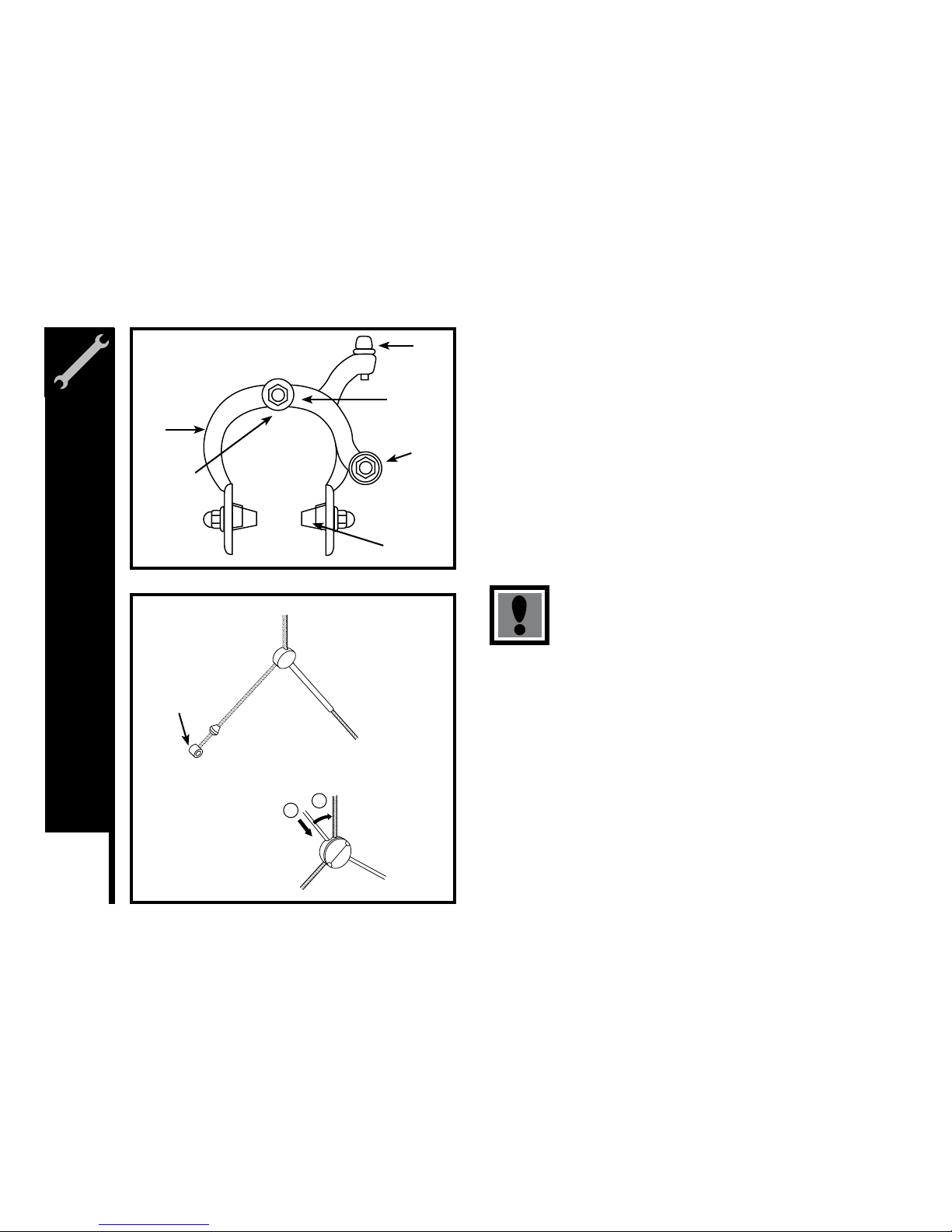
Side Pull Brake
Loosen the cable anchor nut and thread the brake cable through it.
Tighten the nut by hand until it holds the cable in place. Squeeze the
brake arms together against the rim of the wheel. Loosen the nuts on the
brake shoes and turn until they match the angle of the rim. Tighten the
nuts securely. Pull down on the end of the brake cable with pliers, hold
taut and securely tighten the cable anchor nut. Spin the wheel, the brake
shoes should not contact the rim at any point and should be an equal
distance from the rim on both sides. Make sure all nuts and bolts are
securely tightened. Test the brake levers 20-25 times to take care of any
initial cable stretch. Be sure to tightly secure the brake fixing nut behind
the fork.
Cantilever Brakes – Link Wire
If fitted with cantilever type brakes, insert the brakes cable into the link
wire lead, and notch the cable end into the slot of the left brake arm.
Loosen the anchor bolt on the right brake arm and slide the brake cable
under the tabbed washer. Squeeze both brake arms together so the
brake shoes hit the rim, pull all slack out the brake cable, and tighten the
anchor bolt. With the cable fitted, the straddle holder should sit 10-20mm
above the reflector bracket. Adjust the brake shoes using a 10mm wrench
so that they are parallel with the rim and are positioned 1-2mm away from
the rim. Several adjustments may be necessary to achieve the correct
brake position.
When assembling or adjusting the brakes, make
sure the cable anchor is tight. Failure to securely
tighten the nut could result in brake failure and
personal injury.
Side Pull
Brakes
Cable
Adjusting
Barrel
Center Bolt
Cable
Anchor
Nut
Brake Shoe
Fixing Nut
in Back
Brake
Arm
1. Install the cable into
the cable carrier.
2. Set the cable onto
the straddle holder.
1
2
Cantilever
Brakes
Cable
End
Meijer.com
Page 52
49
ASSEMBLY
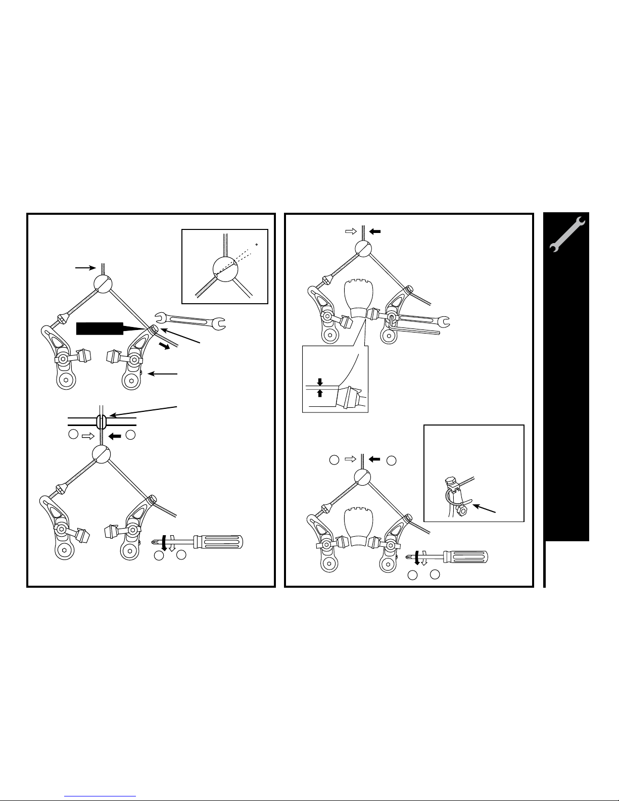
3
3. Temporarily tighten the cable so
that the link wire is at the position in
the illustration.
1
1
2
2
1
1
2
2
5. Secure one of the shoes at a time.
The adjustment of the shoe clearance is
not necessary at this time.
Shoe fixing nut tightening torque:
).sbl .ni 87 - 07( mN 28.8 - 48.7
6. If balance adjustment is necessary,
adjust with the spring tension
adjustment screw.
1 mm
10 mm wrench
5 mm Allen key
Cable Anchor Bolt
To u c h i ng
End cap
Cut off any unnecessary cable, attach an end
cap, and hook it onto the
notched part of the nut
which secures the shoe.
Cable Casing Holder
Link Wire
Spring tension
adjustment screw
4. Turn the spring tension
adjustment screw so that the link
wire comes to a position directly
below the cable casing holder.
Meijer.com
Page 53
50
ASSEMBLY
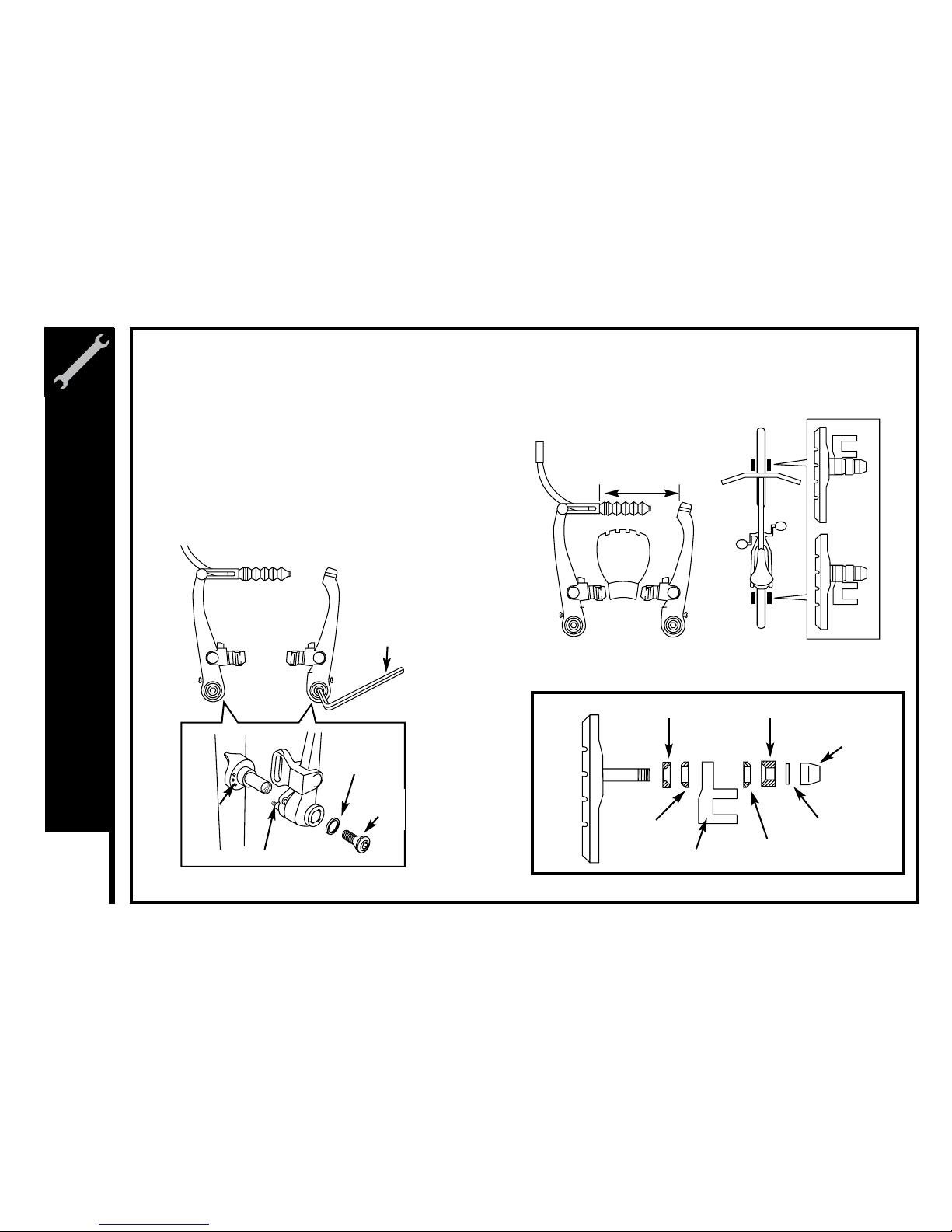
V - Brake
If fitted with V-Brakes, insert the brake body into
the center spring hole in the frame mounting
boss, and then secure the brake body to the
frame with the link fixing bolt.
1.
While holding the shoe against the rim, adjust the
amount of shoe protrusion by interchanging the
position of the B washers (i.e. 6 mm and 3 mm) so that
dimension A is kept at 39 mm or more.
2.
5 mm Allen key
Washer
Link
fixing
bolt
Stopper pin
Spring
hole
39 mm or more
A
3 mm washer B 6 mm washer B
Washer A
Shoe fixing link
Washer A
Washer
Shoe fixing nut
Meijer.com
Page 54
51
ASSEMBLY
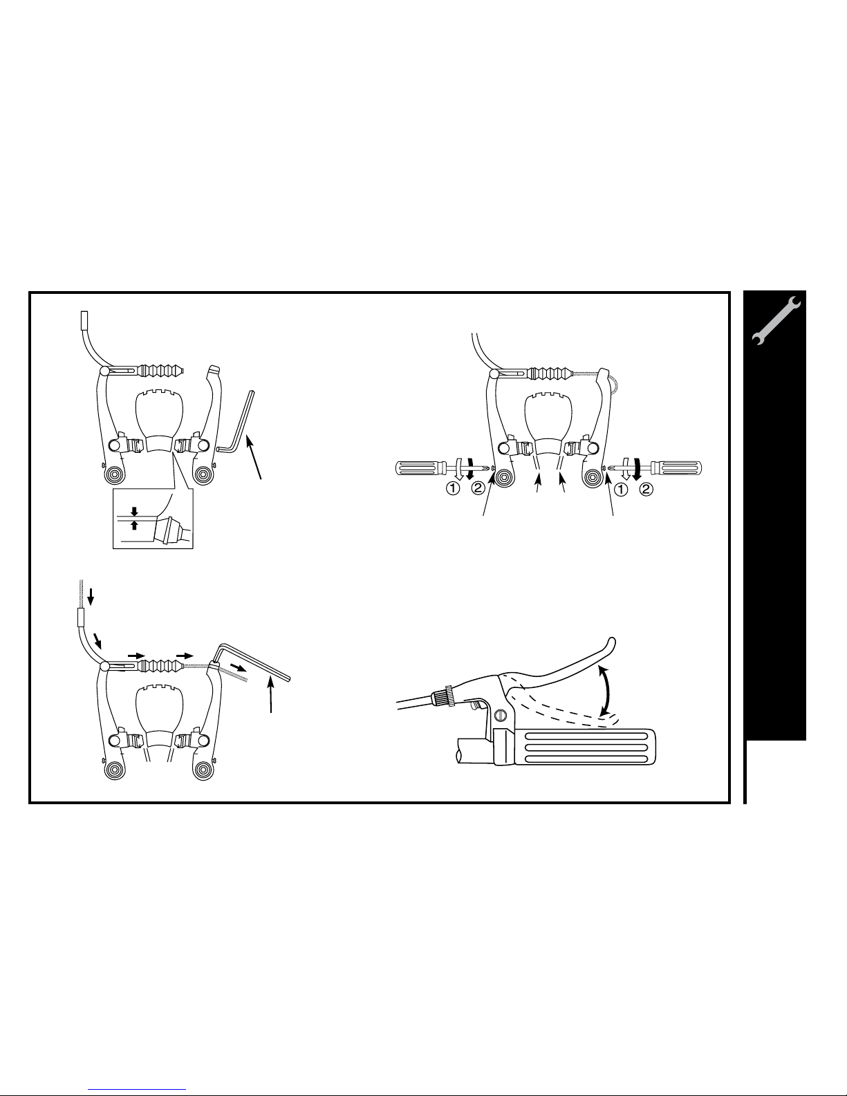
While holding the shoe against the
rim, tighten the shoe fixing nut.
3.
Adjust the balance with the spring
tension adjustment screws.
5.
Depress the brake lever about 10 times as
far as the grip to check that everything is
operating correctly and that the shoe
clearance is correct before using the brakes.
6.
Pass the inner cable through the inner
cable lead. Set the cable with a clearance
of 1mm between each brake pad and the
rim, tighten the cable fixing bolt.
4.
5 mm Allen key
5 mm Allen key
1mm 1mm
1 mm
Spring tension
adjustment screw
Spring tension
adjustment screw
Depress about
10 times
1 mm 1 mm
shoe fixing nut
Meijer.com
Page 55
52
ASSEMBLY
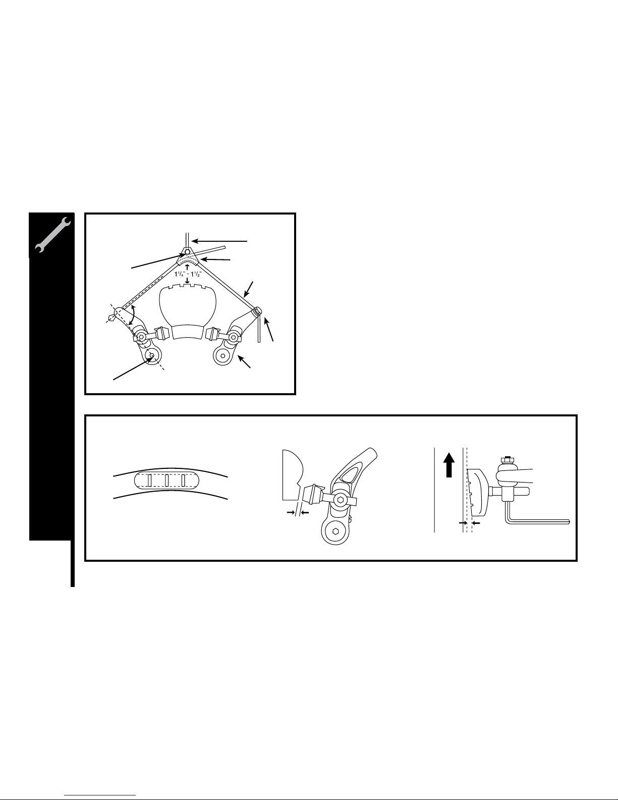
Cantilever Brakes – Straddle Cable
The length of the straddle cable, the height of the straddle hanger and
the brake pad-to-caliper arm position all have an effect on braking
power. Generally, the straddle cable bridge is set low and close to the
tire for maximum braking force. The straddle cable should be high
enough, however, to adequately clear the tire (and any debris that may
stick to the tire) or to fit over the front reflector hanger. In the event
of brake cable failure, the front reflector hanger would prevent the
straddle cable from catching in the tire and locking up the front wheel.
The straddle cable length (when adjustable) is set to transfer as much
force to the brake pads as possible. For the most efficient transfer of
force, the straddle cable and the line between the cantilever pivot and
the cable anchor should form a right angle (90 degrees). If the force is
not at a right angle, part of the force gets wasted in pulling on the brake
post, which has no effect on braking.
Brake pad aligned with the rim surface Pad and rim should be parallel.
Direction of rim
rotation
0.5 - 1.0 mm
1- 2 mm
Straddle
Cable
Brake
Brake Cable
Straddle Hanger
Straddle Cable
Cable
Anchor
Caliper Arm
Pinch Bolt
Pivot
90
o
Meijer.com
Page 56
53
ASSEMBLY
Check your Brakes
Press each brake lever to make sure that there is no binding and that brake pads press hard enough on the rims to stop the bike. The
brake pads should be adjusted so they are 1mm to 2mm away from the rim when the brakes are not applied. Brake pads should be
centered on the rim and the rear portion of each brake pad should be about 0.5 – 1.0mm farther from the rim than the front portion of the
brake pad.
Do not ride the bicycle until the brakes are functioning properly. To test,
apply the brakes while trying to push the bike forward to make sure they
will stop the bicycle.
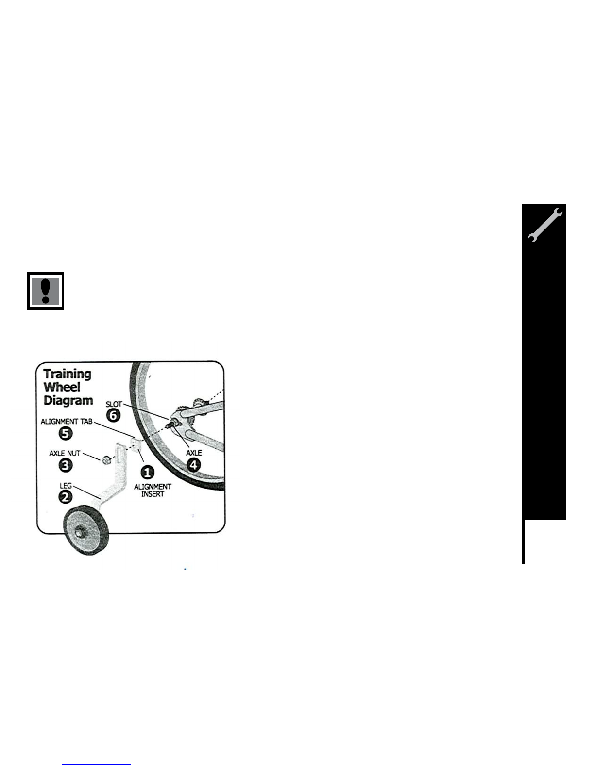
Attach the legs to the bicycle frame:
Put the alignment insert (1), a leg (2), and an axle nut (3) on each end of
the rear wheel axles (4)
Make sure the tab of the alignment insert (5), is to the rear of the axle and
in the slot (6) of the frame.
Make sure both training wheels are the same distance from the ground
Tighten the axle nuts securely.
WARNING: Before each ride, make sure both nuts are tight. Also make sure both
training wheels are the same distance from the ground.
As your child’s ability and balance improve, you may raise or remove the training
wheels.
To move the training wheels, loosen the nut, slide the leg to the correct position, and
retighten the nut.
To remove the training wheels, remove the nut, leg, and alignment insert.
Training Wheels
Meijer.com
Page 57
54
ASSEMBLY
Rotors
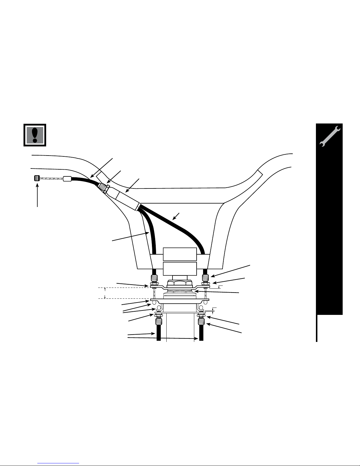
Some freestyle BMX bicycles come equipped with a detangler
system that will allow the handlebar to spin 360-degrees without
binding the cables. It is very important that this system is adjusted
correctly. Installation should only be done by a qualified bicycle
mechanic with the correct tools.
Upper Cable
1. First connect the barrel end of the upper cable to the rear brake
lever. Make sure the long cable casing is on top of the short
cable casing; otherwise, the upper cable will have a twist in it.
2. Route the upper cable through the handlebars (below the
crossbar) with the short cable casing on the same side as the
rear brake lever.
3. Connect the upper cable to the upper plate by passing the
football ends of the upper cable through the threaded holes in the
upper plate and connecting them to the bearing.
4. Screw the adjusting barrels into the upper plate. Don’t tighten
the locknut at this time.
Lower Cable
1. Slide the cable casing through the cable guide on the frame.
2. Connect the lower cable to the lower plate by passing the football
ends of the lower cable through the threaded holes in the lower
plate and connecting them to the bearing.
3. Screw the adjusting barrels into the lower plate. Don’t tighten the
locknut at this time.
4. Connect the lower cable to the rear brake. Don’t adjust the rear
brake at this time. Check to make sure all 11 cable casing ends
on the upper and lower cables are seated correctly, and that the
spring tension of the rear brake is pulling the bearing down.
Adjustment
1. Screw the cable adjusters on the rear brake lever and the upper
cable splitter all the way in.
2. Screw the adjusting barrels in the upper plate in (or out) to set
the bearing for maximum travel. The bearing should be as
far down as it can go without resting on the lower plate or the
adjusting barrels screwed into the lower plate.
3. Use the adjusting barrels that are screwed into the upper plate
to make the bearing parallel to the upper plate. Use a 10mm
wrench to tighten the locknut on the left adjusting barrel of the
upper cable. Leave the right adjusting barrel loose.
4. Screw the lower cable-adjusting barrel into (or out of) the lower
plate until they are as close to the bearing as they can get
without touching it.
5. Screw the cable adjuster on the upper cable splitter out until all
slack is removed from the upper cable. Then screw the cable
adjuster out one more turn to raise the bearing an additional
1mm away from the lower cable adjusting barrels.
CAUTION: Don’t screw the cable adjuster on the upper cable
splitter out more than 8mm. Use the cable adjuster on the rear
brake lever if more adjustment is needed.
6. Check for bearing flop by placing the handlebars in the normal
riding position; then quickly rotate the handlebars back and forth.
Perform the following steps to eliminate bearing flop. NOTE: The
bearing should never be allowed to rest on the lower plate or
lower cable adjusting barrels.
a. Screw the lower cable adjusting barrels out of (or into) the
lower plate until all of the bearing flop is eliminated.
b. Tighten the locknut of the right adjusting barrel on the lower
cable.
c. Rotate the handlebars 180 degrees and recheck for bearing
flop. If there is any bearing flop, use the “loose” adjusting barrels
on the upper and lower cable to remove it.
d. Repeat steps (6a) and (6c) until the handlebars can be rotated
360 degrees without any bearing flop.
7. Finish adjusting the rear brakes.
Meijer.com
Page 58
55
ASSEMBLY
Barrel End
Single Cable Casing
Cable Adjuster
Cable Splitter
Upper Cable
(short casing)
Upper Cable
(long casing)
Upper Plate
Bearing
Football Ends
Lower Plate
Lower Cable
Adjusting Barrel
Locknut
Keyed Washer
Locknut
Adjusting Barrel
37mm + or - 1mm
Set for Max. Travel
Minimum 1mm (1/32 )
Failure to adjust correctly may result in loss of
braking power and personal injury.
Meijer.com
Page 59
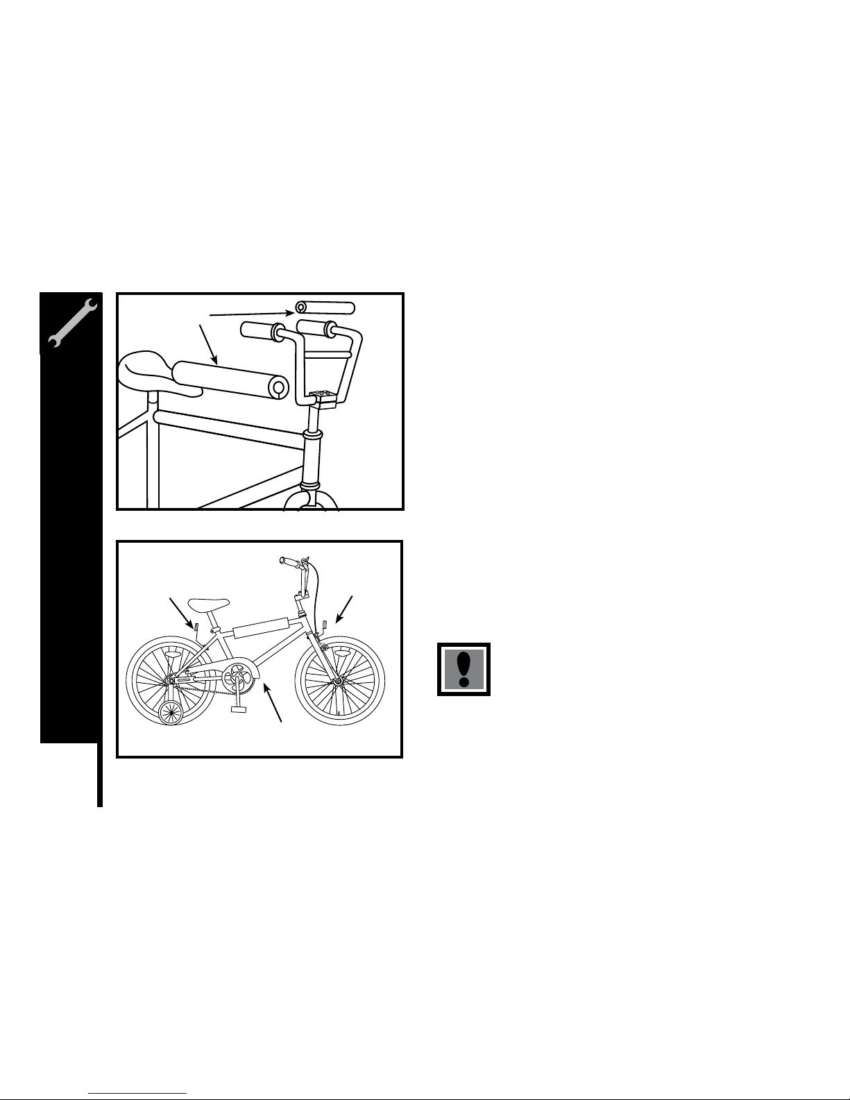
56
ASSEMBLY
Final Check
Install any additional parts that are supplied with your bike.
NOTE: Your bicycle may be equipped with different style components
than the ones illustrated.
Reflectors: Attach the white reflector to the front bracket and the red
reflector to the rear bracket using a 8mm wrench or a Phillips head
screwdriver. Attach the brackets to the bicycle using the hardware
provided. For some models, the front reflector bracket will be mounted on
the front brake assembly bolt that fits through the fork. It is important to
make sure all connections are tightened securely and that the reflectors
are properly angled.
Pads: If your bike is supplied with pads, wrap the foam inner cushion
around the appropriate bar. Place the outer cover over the inner cushion
and press the velcro together securely. Turn the pad so the velcro faces
the ground.
Chainguards: If not already attached, attach the chainguard to the bicycle
frame using the clamps provided. Secure in place making sure the guard
does not bind or get caught on the chain.
Tire Pressure: Check tire pressure, inflate to the range recommended on
the tire sidewalls.
Before riding, ensure all nuts, bolts and fittings on the
bicycle have been correctly tightened.
Pads
Rear
Reflector
(Red)
Front
Reflector
(White)
Chainguard
Meijer.com
Page 60
SERVICING
Meijer.com
Page 61
ROUTINE MAINTENANCE
Correct routine maintenance of your new bike will ensure:
Smooth running – Longer lasting components – Safer riding – Lower running costs
Every time you ride your bicycle, its condition changes. The more you ride, the more frequently maintenance will be required. We
recommend you spend a little time on regular maintenance tasks. The following schedules are a useful guide and by referring to Part 5
of this manual, you should be able to accomplish most tasks. If you require assistance, we recommend you see a bicycle specialist.
Schedule 1 - Lubrication
Frequency Component Lubricant How to Lubricate
Weekly chain chain lube or light oil brush on or squirt
derailleur wheels chain lube or light oil brush on or squirt
derailleurs oil oil can
brake caliper oil 3 drops from oil can
brake levers oil 2 drops from oil can
Monthly shift levers lithium based grease disassemble
Every Six Months Freewheel oil 2 squirst from oil can
brake cables lithium based grease disassemble
Yearly bottom bracket lithium based grease disassemble
pedals lithium based grease disassemble
derailleur cables lithium based grease disassemble
wheel bearings lithium based grease disassemble
headset lithium based grease disassemble
seat pillar lithium based grease disassemble
58
SERVICING
Meijer.com
Page 62
59
SERVICING
Schedule 2 - Service Checklist
Frequency Task Page Reference
Before every ride Check tire pressure 63
Check brake operation 74-77
Check wheels for loose spokes 62
Make sure nothing is loose 62
After every ride Quick wipe down with damp cloth 22-23
Weekly Lubrication as per schedule 1 58
Monthly Lubrication as per shecdule 1 58
Check derailleur adjustment 87-89
Check brake adjustment 74-77
Check brake and gear cable adjustment 69,74
Check tire wear and pressure 63
Check wheels are true and spokes tight 62
Check hub, head set and crank bearings for looseness 64,70,81
Check that pedals are tight 78
Check that handlebars are tight 66
Check that seat and seat post are tight and comfortably adjusted 72
Check frame and fork for trueness 71
Check all nuts and bolts are tight
Every Six Months Lubrication as per shedule 1 58
Check all points are per monthly service 59
Check and replace brake pads, if required 77
Check chain for excess play or wear 84
Yearly Lubrication as per shedule 1 58
Meijer.com
Page 63
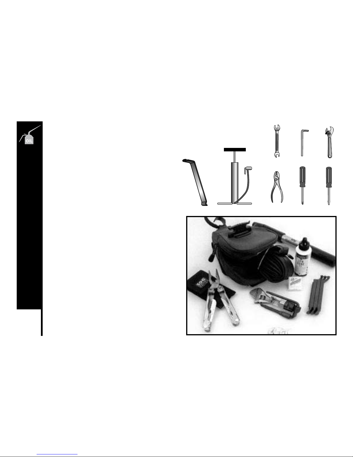
60
SERVICING
Tools Required
1. Open ended wrench or ring wrenches: 8mm, 9mm,
10mm, 12mm, 13mm, 14mm, 15mm
2. Open end or pedal wrench 15mm
3. Allen key wrenches: 4mm, 5mm, 6mm, 8mm
4. Adjustable wrench
5. Standard flat head screwdriver
6. Standard Phillips head screwdriver
7. Standard slip joint pliers
8. Tire pump
9. Tube repair kit
10. Tire levers
Travel Tools
1. Spare Tube
2. Patch kit
3. Pump
4. Tire levers
5. Muti-tool
Meijer.com
Page 64
DETAILED MAINTENANCE
Meijer.com
Page 65
WHEELS AND TIRES
Wheel Inspection
It is most important that wheels are kept in top condition. Properly maintaining your bicycle’s wheels will help braking performance and
stability when riding. Be aware of the following potential problems:
Dirty or greasy rims:
Caution: These can render your brake ineffective. Do not clean them with oily or greasy materials. When cleaning, use a clean rag or
wash with soapy water, rinse and air dry. Don’t ride while they’re wet. When lubricating your bicycle, don’t get oil on the rim braking
surfaces.
Wheels not straight:
Lift each wheel off the ground and spin them to see if they are crooked or out of round. If wheels are not straight, they will need to be
adjusted. This is quite difficult and is best left to a bicycle specialist.
Broken or loose spokes:
Check that all spokes are tight and that none are missing or damaged.
Caution: Such damage can result in severe instability and possibly an accident if not corrected. Again, spoke repairs are best handled
by a specialist.
Loose hub bearing:
Lift each wheel off the ground and try to move the wheel from side to side.
Caution: If there is movement between the axle and the hub, do not ride the bicycle. Adjustment is required.
Axle nuts:
Check that these are tight before each ride.
Quick release:
Check that these are set to the closed position and are properly tensioned before each ride.
Caution: Maintain the closed position and the correct adjustment. Failure to do so may result in serious injury.
6262
DETAILED MAINTENANCE
Meijer.com
Page 66
63
DETAILED MAINTENANCE
Tire Inspection
Tires must be maintained properly to ensure road holding and stability. Check the following areas:
Inflation: Ensure tires are inflated to the pressure indicated on the tire sidewalls. It is better to use a tire gauge and a hand
pump than a service station pump. Caution: If inflating tires with a service station pump, take care that sudden over
inflation does not cause tire to blow up.
Bead
Seating:
When inflating or refitting tire, make sure that the bead is properly seated in the rim.
Tread: Check that the tread shows no signs of excessive wear or flat spots, and that there are no cuts or other damage.
Caution: Excessively worn or damaged tires should be replaced.
Valves: Make sure valve caps are fitted and that valves are free from dirt. A slow leak caused by the entry of the dirt can lead
to a flat tire, and possibly a dangerous situation.
Recommended Tire Pressures:
The recommended pressure molded on the sidewall of your bicycle tires should match the following chart. Use this as a general guide.
BMX 35 – 50 p.s.i
MTB 40 – 65 p.s.i
Road Touring 70 – 90 p.s.i
Road Racing 110 – 125 p.s.i
Hybrid/Crossbike 60 – 100 p.s.i
Meijer.com
Page 67
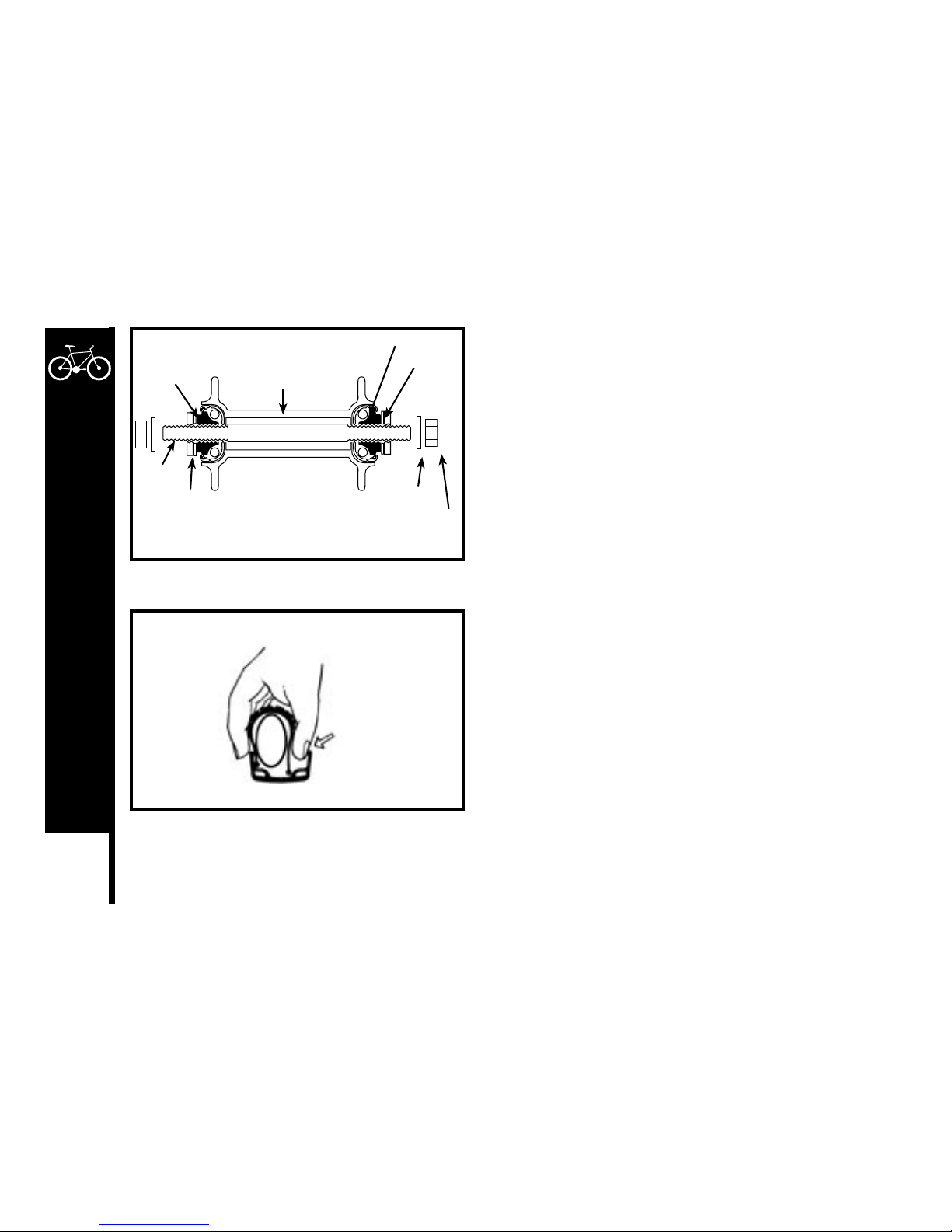
64
DETAILED MAINTENANCE
Hub Bearing Adjustment
When checked, the hub bearings of either wheel will require adjustment if
there is any more than slight side play.
1. Check to make sure neither locknut is loose.
2. To adjust, remove wheel from bicycle and loosen the locknut on one
side of the hub while holding the bearing come on the same side with
a flat open-end wrench.
3. Rotate the adjusting cone as needed to eliminate free play.
4. Re-tighten the locknut while holding the adjusting cone in position.
5. Re-check that the wheel can turn freely without excessive side play.
How To Fix a Flat Tire
If you need to repair a tire, follow these steps:
1. Remove the wheel from the bicycle.
2. Deflate the tire completely via the valve.
Loosen the tire bead by pushing it inward all the way around.
3. Press one side the tire bead up over the edge of the rim.
Note: Use tire levers, not a screwdriver, otherwise you may damage
the rim.
4. Remove the tube, leaving the tire on the rim.
5. Locate the leaks and patch using a tube repair kit, carefully following
the instructions, or replace the tube.
Note: Ensure that the replacement tube size matches the size stated
on the tire sidewall and that the valve is the correct type for your
bicycle.
6. Match the position of the leak in the tube with the tire to locate the
possible cause and mark the location on the tire.
7. Remove the tire completely and inspect for a nail, glass, etc. and
remove if located. Also inspect the inside of the rim to ensure there
Lock
Washer
Axle
Lock Nut
Hub Body
Ball Bearings
Bearing
Cone
Washer
Axle Nut
Push tire bead
into the center
of the rim.
Meijer.com
Page 68
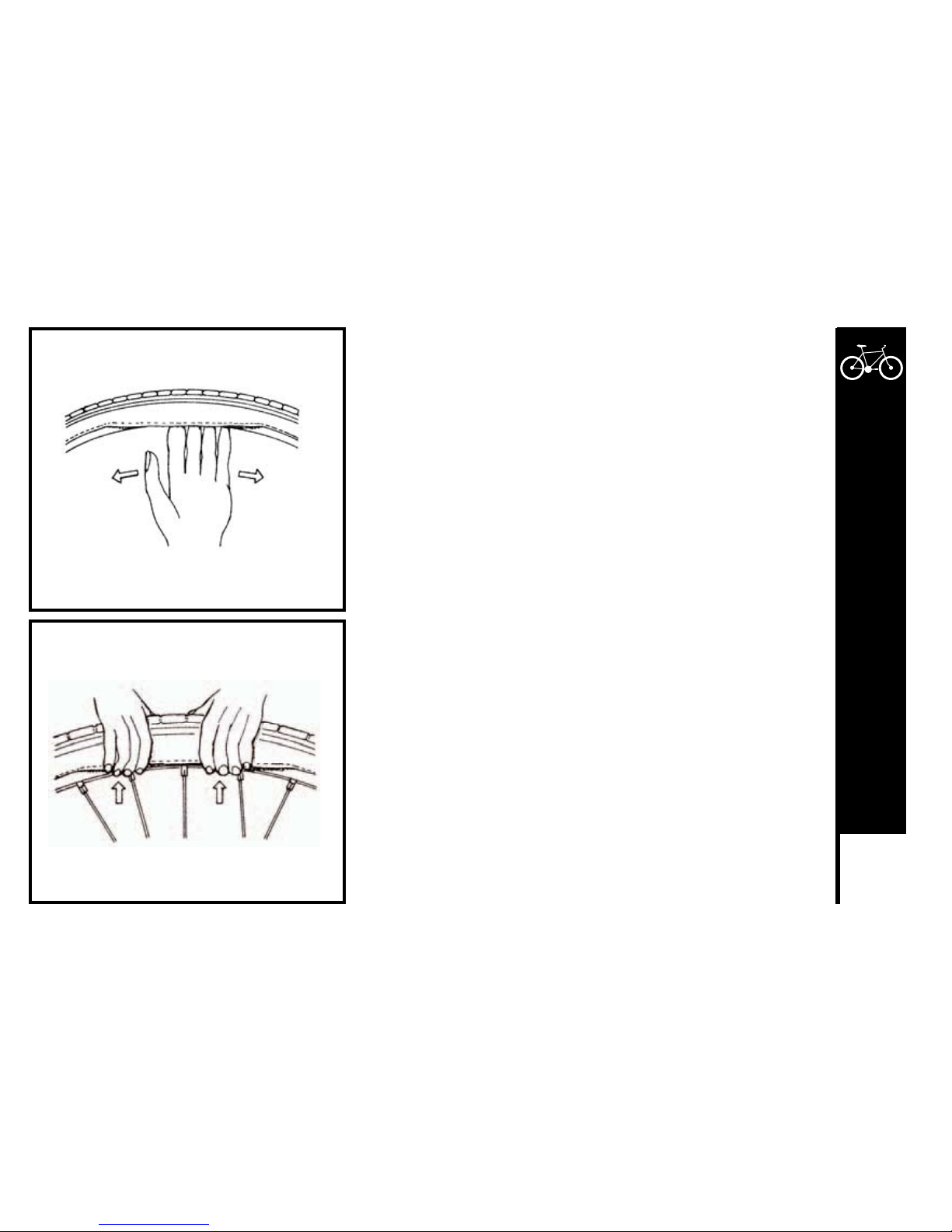
65
DETAILED MAINTENANCE
are no protruding spokes, rust or other potential causes. Replace the
rim tape, which covers the spoke ends, if damaged.
8. Remount one side of the tire onto the rim.
9. Using a hand pump, inflate the tube just enough to give in some shape.
10. Place the valve stem through the hole in the rim and work the tube into
the tire. Note: Do not let it twist.
11. Using your hand only, remount the other side of the tire by pushing the
edge toward the center of the rim. Start on either side of the valve and
work around the rim.
12. Before the tire is completely mounted, push the valve up into the rim to
make sure the tire can sit squarely in position.
13. Fit the rest of the tire, rolling the last, most difficult part on using your
thumbs. Note: Avoid using tire levers as these can easily puncture the
tube or damage the tire.
14. Check that the tube is not caught between the rim and the tire bead at
any point.
15. Using a hand pump, inflate the tube until the tire begins to take shape,
and check that the tire bead is evenly seated all the way around the rim.
When properly seated, fully inflate the tire to the pressure marked on the
sidewall. Use a tire air pressure gauge to check.
16. Replace the wheel into the frame checking that all gears, brakes and
quick release levers are properly adjusted.
Remove tire bead from the rim.
Pull tire back onto the rim.
Meijer.com
Page 69
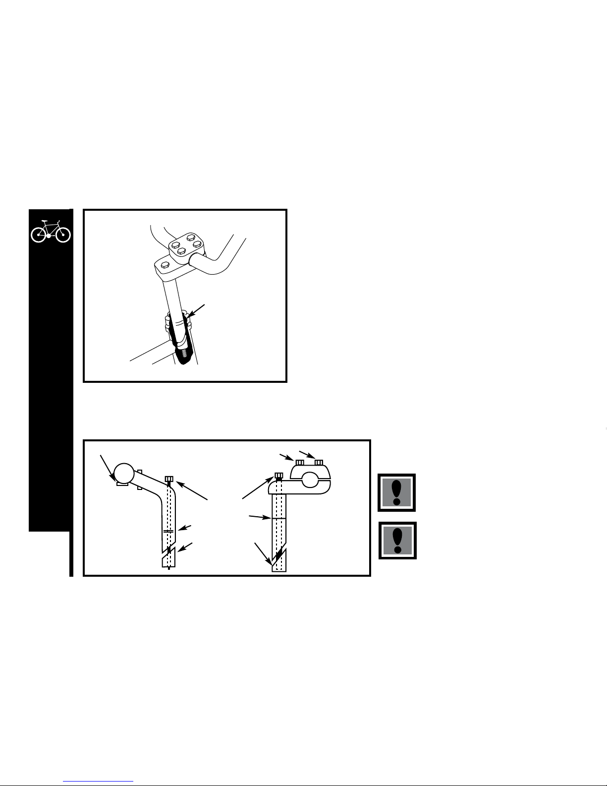
66
DETAILED MAINTENANCE
HANDLEBARS AND STEM
Handlebar Stem
The handlebar stem fits into the steering column and is held firm by the action
of a binder bolt and expander wedge which, when tightened, binds with the
inside of the fork steerer tube.
When removing the stem, loosen the stem bolt two or three turns; then give it a
tap to loosen the wedge inside.
Lubricate by first wiping off any old grease and grime; then applying a thin film
of grease to the part, including the wedge, that will be inserted into the frame.
The height of the handlebar can be adjusted to suit your comfort preference.
If the stem is removed from the steering column, you will notice a mark about
65mm up from the bottom with the words “max. height” or “minimum insertion.”
WARNING
It’s important that the top plate remain parallel to the bottom plate to apply equal force to the handlebar. To achieve this the four bolts
must be tightened at the same rate. To achieve this tighten each bolt with the tool provided until you feel them start to “grab” (beginning
to tighten). Now spin the handlebars up to the correct riding position and continue to tighten the four bolts and repeat the steps.
Never ride a bicycle if the stem has been
raised so that the max. height/minimum
insertion line can be seen.
Warning: Over-tightening the stem bolt
or headset assembly may cause damage
to the bicycle and/or injury to the rider.
Max. Height/
Minimum Insertion
Mark
Handlebar Clamp Bolts
Handlebar Binder Bolt
Stem Bolt
Max. Height/
Min. Insertion Mark
Stem Bolt Wedge
Meijer.com
Page 70
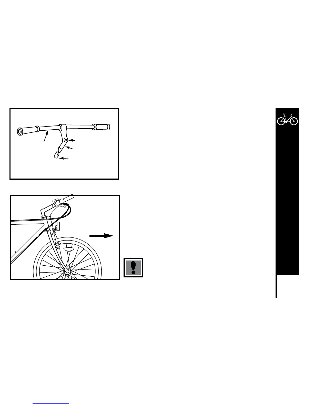
67
DETAILED MAINTENANCE
When refitting the stem, make sure the handlebars are correctly aligned and
tightened using the appropriate hex wrench or Allen key.
Do not over-tighten.
Test the security of the handlebar within the stem, and the stem with the fork
steerer tube, by clamping the front wheel between your knees and trying
to move the handlebar up and down, and from side to side. The handlebar
should not move when applying turning pressure.
Handlebars
The exact positioning of the handlebar is a matter of personal comfort. For
MTB bicycles, the bar should be approximately horizontal, with the ends
pointing back and slightly up. On BMX bicycles, the handlebar should remain
in an approximately upright position but can be angled back or forward
slightly for comfort. On MTB and racing style bicycles, the handlebar is
usually tightened in the stem by a single Allen key bolt or hexagonal bolt. On
BMX style bicycles there may be four clamping bolts.
Make sure, when setting the handlebars in the fork, that the curved
rake of the fork is angled to the front of the bicycle.
Please not that if you need to replace the forks in your bicycle at any time,
the replacement forks must have the same rake and the same tube inner
diameter as those originally fitted to the bicycle.
Never ride unless the handlebar clamping mechanism has
been securely tightened.
MTB Handlebar Assembly
Grip
Handlebar
Stem Wedge Bolt
Handlebar Stem
Stem Bolt Wedge
Make sure
handlebars and
fork are facing
forward
Note, curved rake of
fork faces forward
Meijer.com
Page 71
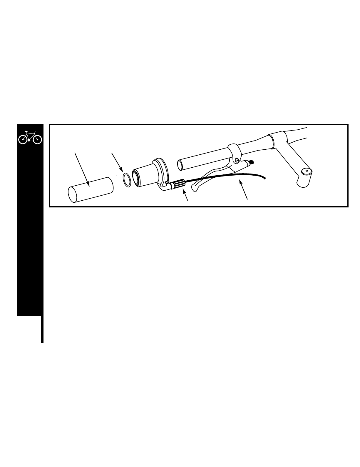
68
DETAILED MAINTENANCE
TWIST SHIFTERS
Twist Shift – Installation
1. Slide front twist shift assembly over left side of handlebar leaving proper clearance for handlebar grip. If necessary, move the brake
lever to accommodate twist shift and handlebar grip.
2. Rotate assembly until cable exits beneath brake lever with adequate clearance for brake lever movement.
3. Firmly tighten recessed clamp screw. Installation torque should be 20 in.-lbs.
4. Slide the two 7/8” plastic washers over handlebar. The washers prevent the grip from interfering with twist shift rotation.
5. Slide handlebar grip over handlebar. Thread the cable inner wire through cable housings and frame, and attach to derailleur. Make
sure that the cable is in the V groove at the derailleur attachment bolt. If trimming the cable housing is necessary, be sure to replace
the housing end cap.
6. Adjust indexing.
7. Slide rear twist shift over right side of handlebar and repeat steps 2 – 6.
8. Actuate front and rear brake levers to be certain of proper operation. If twist shift interferes with brake lever movement, rotate brake
lever or twist shift. Check for proper lever operation again.
Grip 7/8 Plastic Washer
Barrel Adjuster Cable
Meijer.com
Page 72
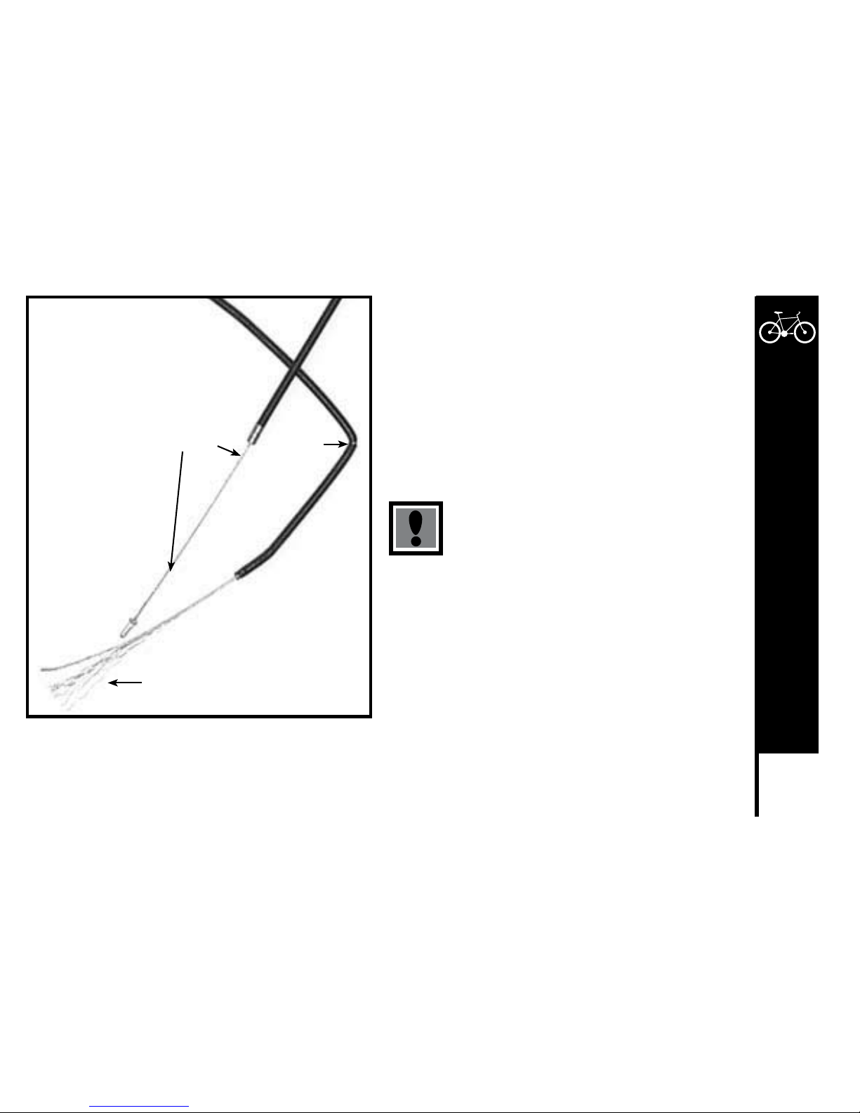
69
DETAILED MAINTENANCE
Cables and Cable Housing
Cables and housing are one of the most overlooked parts on the
bicycle. The first indication that your cables and housing need to
be replaced is an increased amount of pressure needed to operate
the brakes or shifters. Before every ride, check that there are
no kinks or frays in the cables and housing. Also check that the
housing is seated properly into each cable stop of the bicycle. It
is recommended that the cables and housing be replaced at least
every riding season to prolong the life of your bike.
Do not ride a bicycle that is not operating properly.
kink
fray
good cable
Meijer.com
Page 73
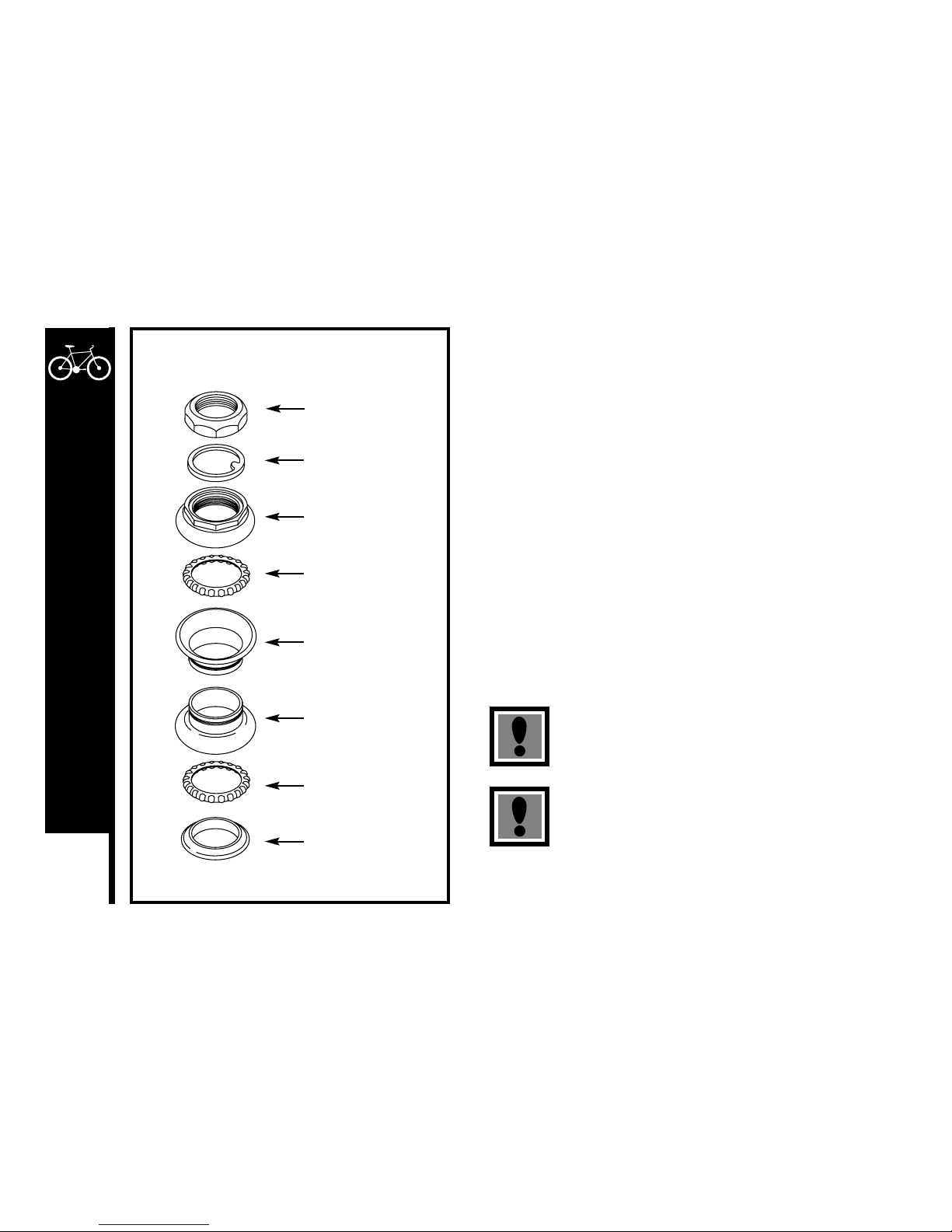
70
DETAILED MAINTENANCE
HEADSET
Inspection
The headset bearing adjustment should be checked every month. This
is important, as it is the headset that locks the fork into the frame, and if
loose, can cause damage or result in an accident.
While standing over the frame top tube with both feet on the ground, apply
the front brake firmly and rock the bicycle back and forth; if you detect any
looseness in the headset, it will need adjustment. Check that the headset
is not over-tightened by slowly rotating the fork to the right and left. If that
fork tends to stick or bind at any point, the bearings are too tight.
Adjustment
Loosen the headset top locknut or remove it completely along with the
reflector bracket, if fitted. Turn the adjusting cup clockwise until finger
tight. Replace the lock washer or reflector bracket and re-tighten the lock
nut using the suitable wrench.
Note: Do not over-tighten or bearing damage will occur.
Always make sure that the headset is properly adjusted
and that the headset locknut is fully tightened before
riding.
Warning: Over-tightening the stem bolt or headset
assembly may cause damage to the bicycle and/or injury
to the rider.
Lock Nut
Lock Washer
Adjusting Cup/Cone
Ball Retainer
Top Head Cup
Bottom Head Cup
Ball Retainer
Crown Race
Standard Headset
Meijer.com
Page 74
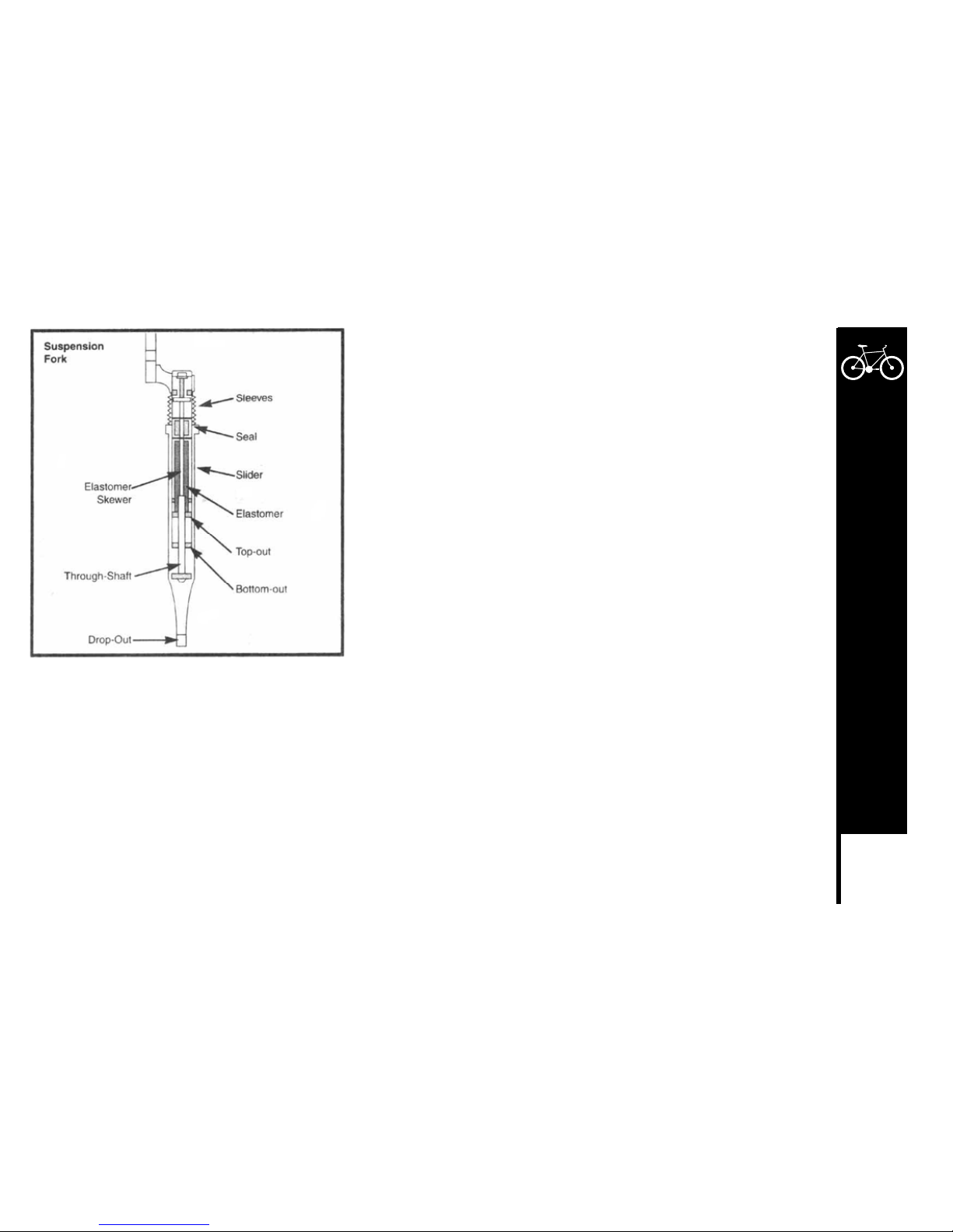
71
DETAILED MAINTENANCE
SUSPENSION FORK
Some fork models differ from the one illustrated. Those models are not
adjustable and require no maintenance other than keeping it free from dirt and
grime.
Regular Maintenance
The following maintenance should be performed every month (if riding off-road)
or whenever you feel performance is deteriorating.
1. With the fork apart, thoroughly clean all parts.
2. Apply a thin coat of grease to the upper tubes, coil springs and all internal
bushings.
Reassembly
1. Slide upper tubes into lower tubes
2. Firmly hold lower tube and turn clockwise until it will not turn anymore.
3. Align the brake arch mounts on both lower tubes and install brake arch.
4. Tighten brake arch bolts to 70-80in-lbs(8-9.2Nm)
Check before each ride:
1. Make sure headset is properly secured.
2. Make sure the exposed portions of the upper tubes are clean.
3. Make sure the quick releases are properly secured.
4. Make sure the front brake cable housing is properly seated into the brake
cable stop.
5. Check tire clearance and clearance between the top of the front brake
straddle cable carrier and the bottom of the cable stop. Make sure the front
brake cable is routed to the brake cable stop located on the brake arch. Do
not route the cable through the stem or any other mounts or cable stops.
Meijer.com
Page 75
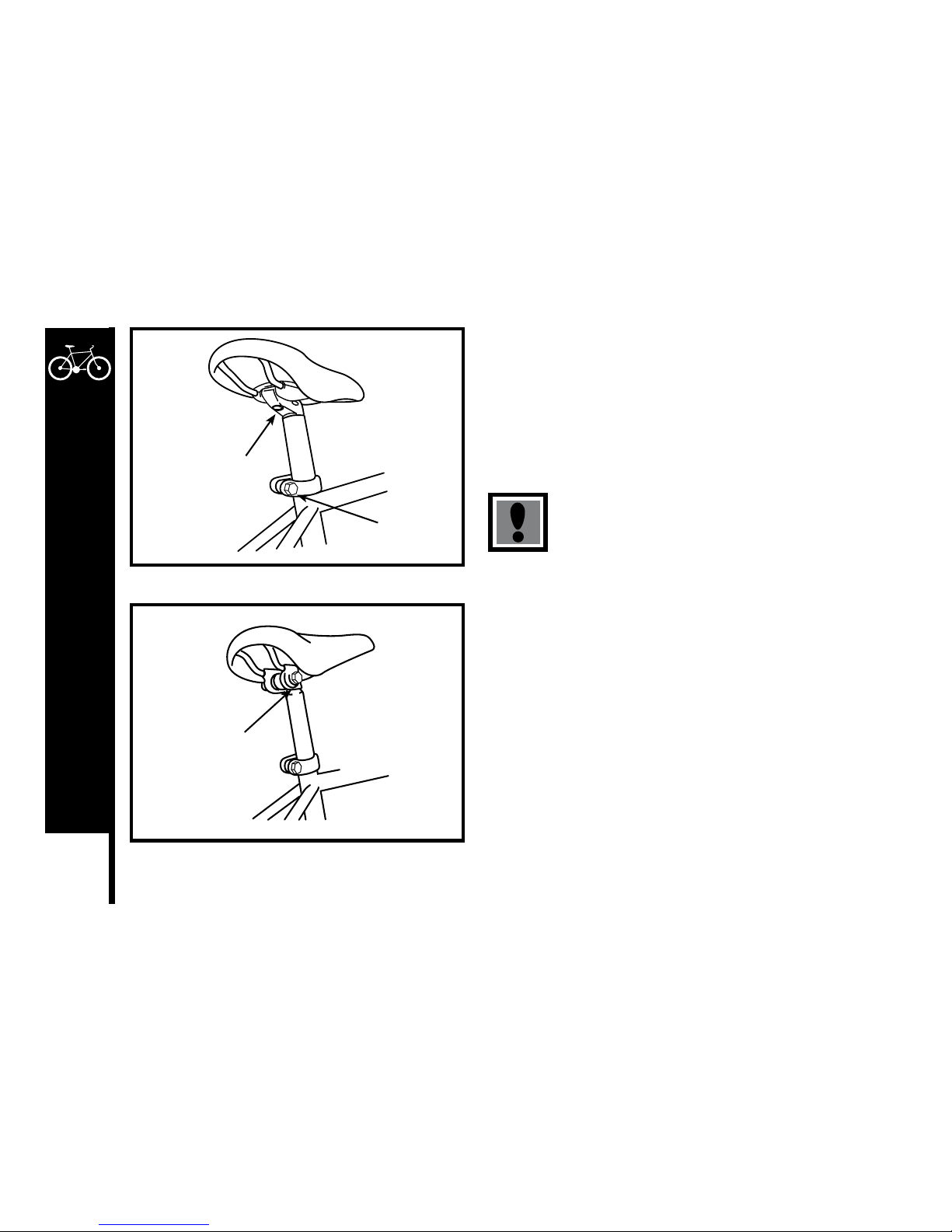
72
DETAILED MAINTENANCE
SADDLE AND SEAT POST
Inspection
The seat fixing bolt and the seat post binder bolt should be checked for
tightness and adjustment every month. On removing the seat post from
the frame, you will notice a mark about 65mm up from the bottom with the
words “max. height” or “minimum insertion.”
To avoid damage to either the seat post, the frame or
possibly the rider, a minimum of 65mm of the seat post
must always remain in the frame.
Lubrication
Remove the seat post from the frame and wipe off any grease, rust or dirt.
Then apply a thin film of new grease to the part that will be inserted into
the frame. Re-insert, adjust and tighten the seat post in the frame.
Seat Fixing Bolt
Micro Adjustable
Seat Post
Seat Post
Binder Bolt
Seat Clamp Nut
Standard
Seat Post
Meijer.com
Page 76
73
DETAILED MAINTENANCE
Adjustment
As mentioned in Part 2, the seat can be adjusted in height, angle and distance from the handlebar to suit the individual rider.
Saddle angle is a matter of personal preference but the most comfortable position will usually be found when the top of the seat is
almost parallel to the ground, or slightly raised at the front.
The saddle can also be adjusted by sliding it forward or back along the mounting rails to obtain the most comfortable reach to the
handlebars.
When fitting, position the seat post into the clamp under the seat and place it in the frame without tightening. Adjust it to the desired
angle and position, and tighten the clamping mechanism.
There are two types of seat clamps commonly in use. The most common employs a steel clamp with hexagonal nuts on either side to
tighten. The other type, known as a micro-adjustable clamp, uses a single vertically mounted Allen head fixing bolt to tighten. After fixing
the seat to the desired position on the post, adjust the height to the required level and tighten the binder bolt.
Note that the type of binder bolt may be a hexagonal bolt, an Allen head bolt, or a quick release mechanism. The operation of the seat
post quick mechanism is the same as for quick release hubs. Refer to p. 27.
Test the security by grasping the seat and trying to turn it sideways. If it moves, you will need to further tighten the binder bolt.
Note: Remember that the minimum insertion mark must remain inside the frame assembly.
Meijer.com
Page 77
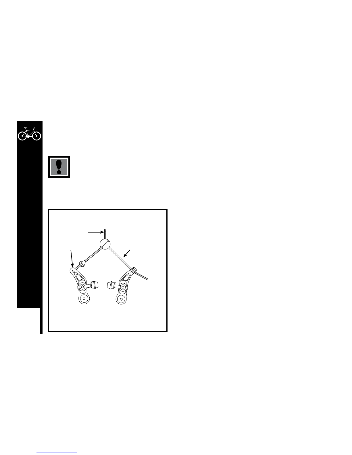
74
DETAILED MAINTENANCE
Brakes
The correct adjustment and operation of your bicycle’s brakes is extremely important for safe operation. Brakes should be checked for
effective operation before every ride. Frequent checking of adjustment is necessary as the control cables will stretch and the brake pads
will become worn with use.
Never ride a bicycle unless the brakes are functioning properly.
There are two types of hand operated bicycle brakes in common use: sidepull calipers and cantilever calipers. Both utilize a handlebar
mounted lever which controls a cable to operate the brake. Sidepull brakes are mounted to the frame or fork via a single pivot point.
Cantilever brakes use two brake pivot arms, each mounted on separate pivots on either side of the frame/fork.
Inspection
Brake levers should be checked for tightness at least every three months.
They should be set in a comfortable position within easy reach of the
rider’s hands, and must not be able to move on the handlebar. Some
brake levers make use of a reach adjustment screw, which can be altered
to the distance between the handlebar grip and the lever, as required. The
brake pads should be checked for correct positioning and tightness before
every ride, and the various bolts and nuts at least every three months.
Squeeze each brake lever to make sure they operate freely and that the
brake pads press hard enough on the rims to stop the bike. There should
be about 1mm – 2mm clearance between each pad and the rim when the
brakes are not applied. The brake pads must be properly centered for
maximum contact with the rim. Replace the brake pads if they are over
worn so that the grooves or pattern cannot be seen. The brake cable
wires should be checked for kinks, rust, broken strands or frayed ends.
The outer casing should also be checked for kinks, stretched coils and
other damage. If the cable are damaged, they should be replaced.
Cantilever Brakes
Brake Cable
Brake Arm
Straddle Cable
Meijer.com
Page 78
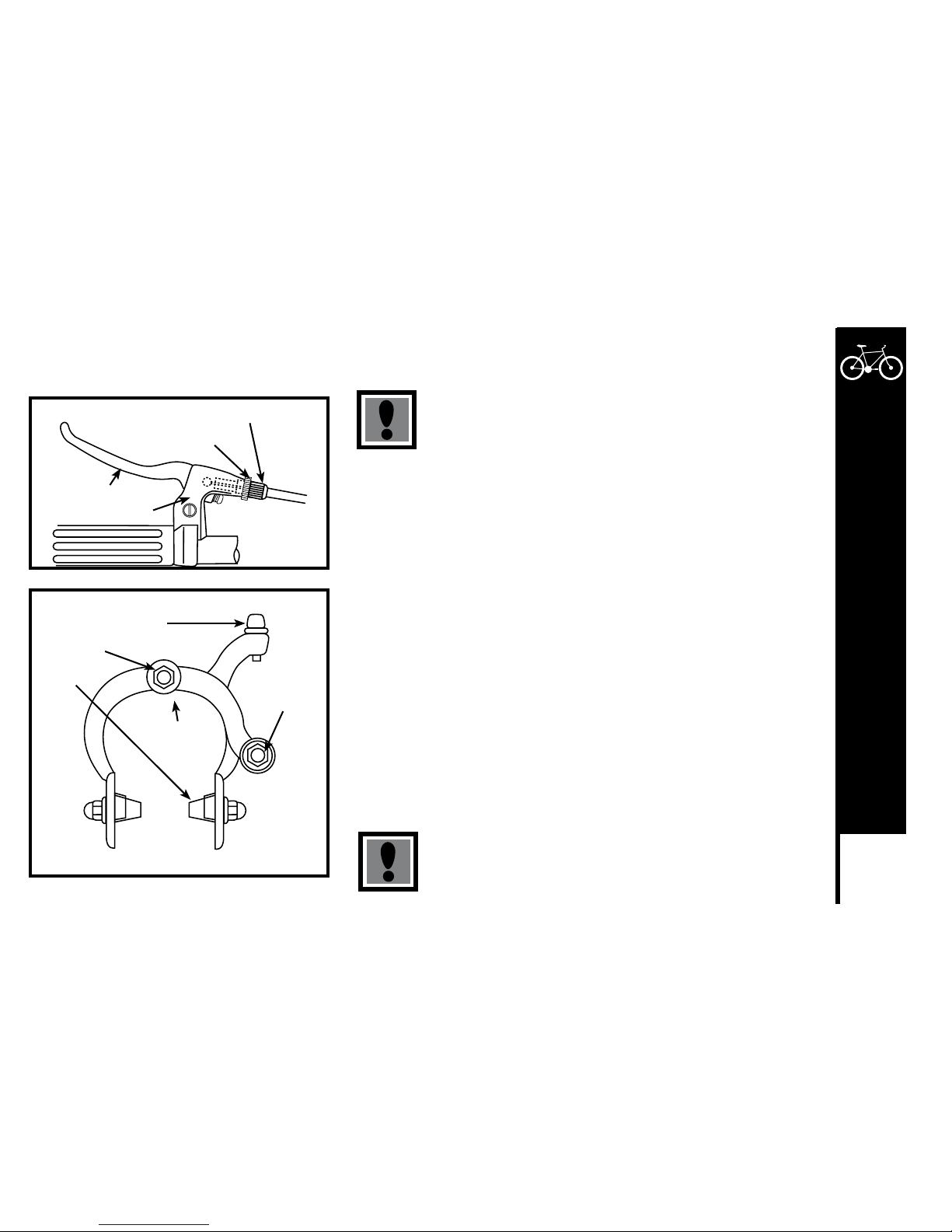
75
DETAILED MAINTENANCE
Some brakes have a quick release mechanism to allow easier wheel removal. Whenever you adjust he brakes make sure that quick
release mechanism is in the closed position.
Never ride unless the quick release is firmly locked in the
closed position.
Lubrication
The brake lever and brake caliper pivot points should be oiled with 2-3 drops of
light oil at least every three months to ensure smooth operation and to reduce
wear. Cables should be greased along their entire length, after removing them
from their casings, at least every six months. Always grease new cables before
fitting.
Adjustment – Sidepull Calipers
Minor brake adjustment can be made via the cable adjusting barrel, usually
located at the upper cable arm. To adjust, squeeze the brake pads against the
rim, loosen the lock nut and turn the adjuster. Brake pad clearance should be a
maximum 2mm form the rim. When correct, re-tighten the lock nut. If the pads
cannot be set close enough to the rim in this manner, you may have to adjust
the cable length. Screw the barrel adjuster 3/4 of the way in, squeeze the pads
against the rim, undo the cable anchor bolt and pull the cable through with
pliers. Re-tighten the cable anchor bolt and apply full force to the brake lever
to test, then fine tune using the barrel adjuster. If one pad is closer to the rim
than the other, loosen the fixing nut at the back of the brake, apply the brake to
hold it centered, and re-tighten the fixing nut.
Ensure the brake fixing nut is secured tightly.
Failure to do this may cause the brake assembly to dislodge
from the fork.
Brake Lever
Brake Lever Housing
Cable Adjusting Barrel
Lock nut
Cable Adjusting Barrel
Center Bolt
Brake Shoe
Side-Pull Brakes
Fixing Nut
in Back
Cable
Anchor
Bolt
Meijer.com
Page 79
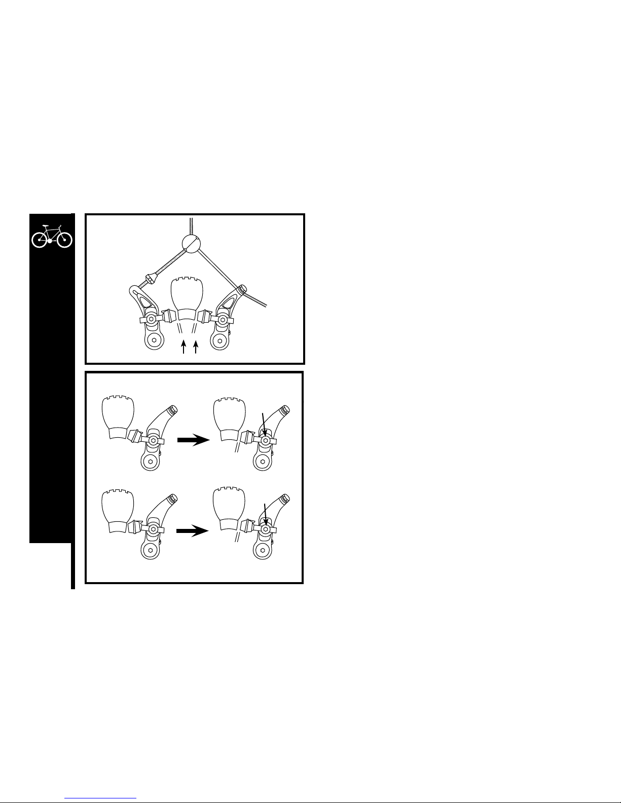
76
DETAILED MAINTENANCE
Some brakes have a special mechanism that enables you to set the
clearance on either side of the rim using a screwdriver. Brake pads
should finally be adjusted so that the leading edge of the pad makes
first contact with the rim. Some brakes have special curved washers to
allow this, but on less complex models it will be necessary to apply a
little force to the pad and its mounting.
Adjustment – Cantilever Calipers
Minor brake adjustment can be made via the barrel cable adjusters that
are located on each brake lever. To adjust, squeeze the brake pads
against the rim, loosen the lock nut, and turn the adjuster to pull the
brake pads closer to, or spread them away from the rim as required.
Brake pad clearance should be a maximum 2mm from the rim.
When correct, re-tighten the lock nut.
If the pads cannot be set close enough to the rim in this manner, you
may have to adjust either the length of the straddle cable or the length
of the brake cable.
If the brakes use a separate brake cable and straddle cable, adjust the
straddle length by first screwing the barrel adjuster 3/4 of the way in,
then loosening the straddle cable fixing bolt, then pulling or pushing the
cable through the fixing bolt.
Check that the straddle bridge is in the middle of the cable to ensure
even brake pad contact. Apply full force to the brake lever to test, then
fine tune using the barrel adjuster.
To adjust the brake cable length, loosen the brake cable fixing bolt on
the cable straddle bridge, adjust the length until the brake shoes are the
correct distance from the rim, then re-tighten and test.
Parallel
Parallel
Fully Adjustable Brake Shoes
Curved
Adjustment
Washer
Curved
Adjustment
Washer
2mm clearance
Meijer.com
Page 80
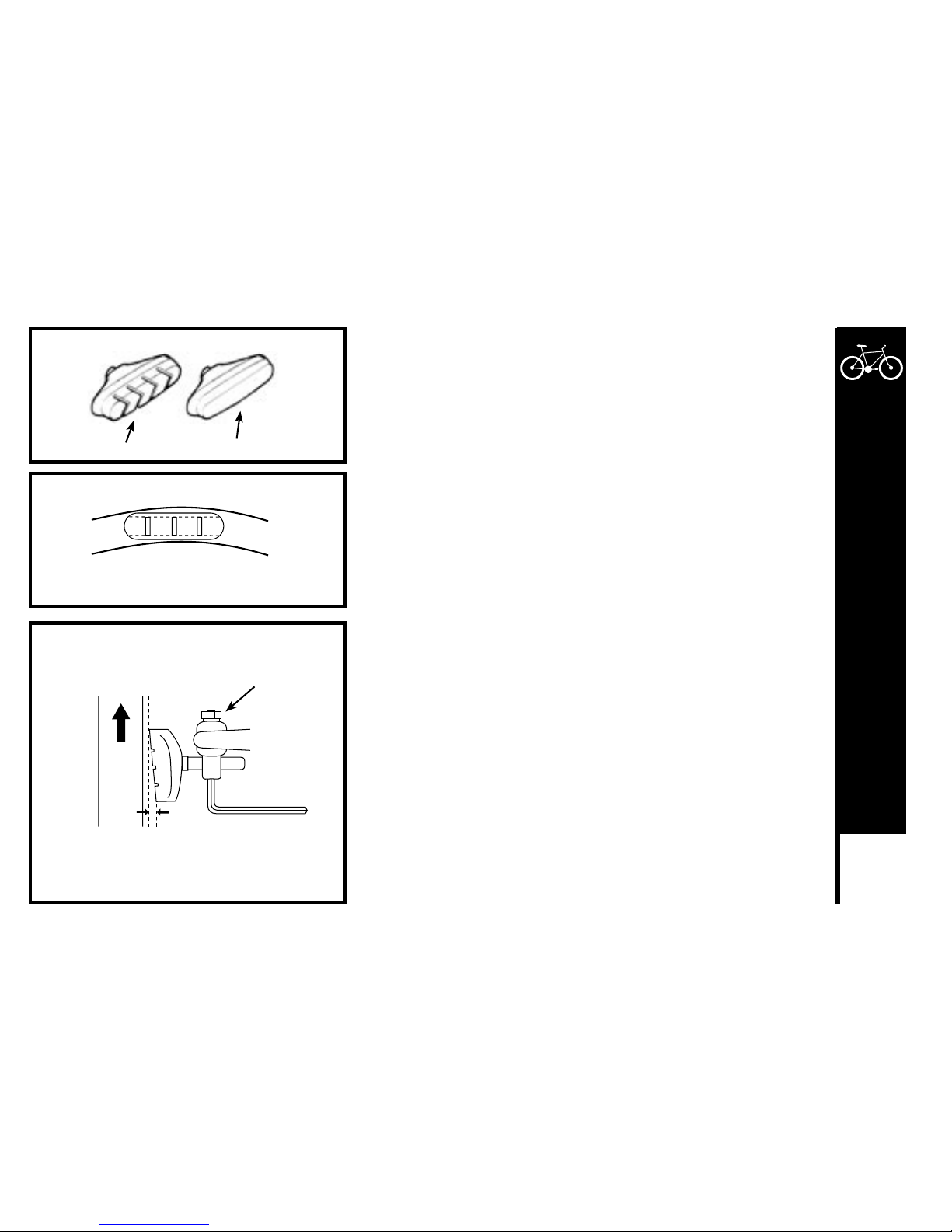
77
DETAILED MAINTENANCE
On some newer type cantilever brakes, the main brake cable continues
through the central cable carrier to an anchor bolt on one of the brake arms.
A shorter link cable reaches form the carrier and the hook on the other brake
arm. Adjustment of the cable length is made after loosening the anchor bolt
on the brake arm. Adjust the brake pad position so that it is parallel to the
wheel rim and so that the leading edge makes first contact.
To do this, fit an Allen key into the brake pad holding bolt, loosen the fixing
nut and adjust. Move the brake pad along its mounting post to alter the
distance from the rim, and move the curved adjustment washer to alter the
angle of the pad.
On some models there is a spring-force adjustment screw on the brake arm
that allows further fine turning of the brake shoe position.
Bicycles with cantilever brakes must be fitted with safety devices to prevent
a possible accident in the event of the brake control cable or the straddle
bridge becoming loose or breaking while riding.
These are usually the reflector brackets, and must be fitted in the front and
rear. The bracket will prevent the straddle cable from interfering with the
wheel should the cable become disconnected from the control cable. If the
reflector brackets are not fitted in this position, then alternative emergency
cable safety stops must still be fitted.
Usable Brake Shoe Worn Out Brake Shoe (Replace)
Tread Tread Worn Off
Align brake shoe with rim surface
Direction of rim
rotation
0.5 - 1.0 mm
Brake Shoe Holding Nut
Meijer.com
Page 81
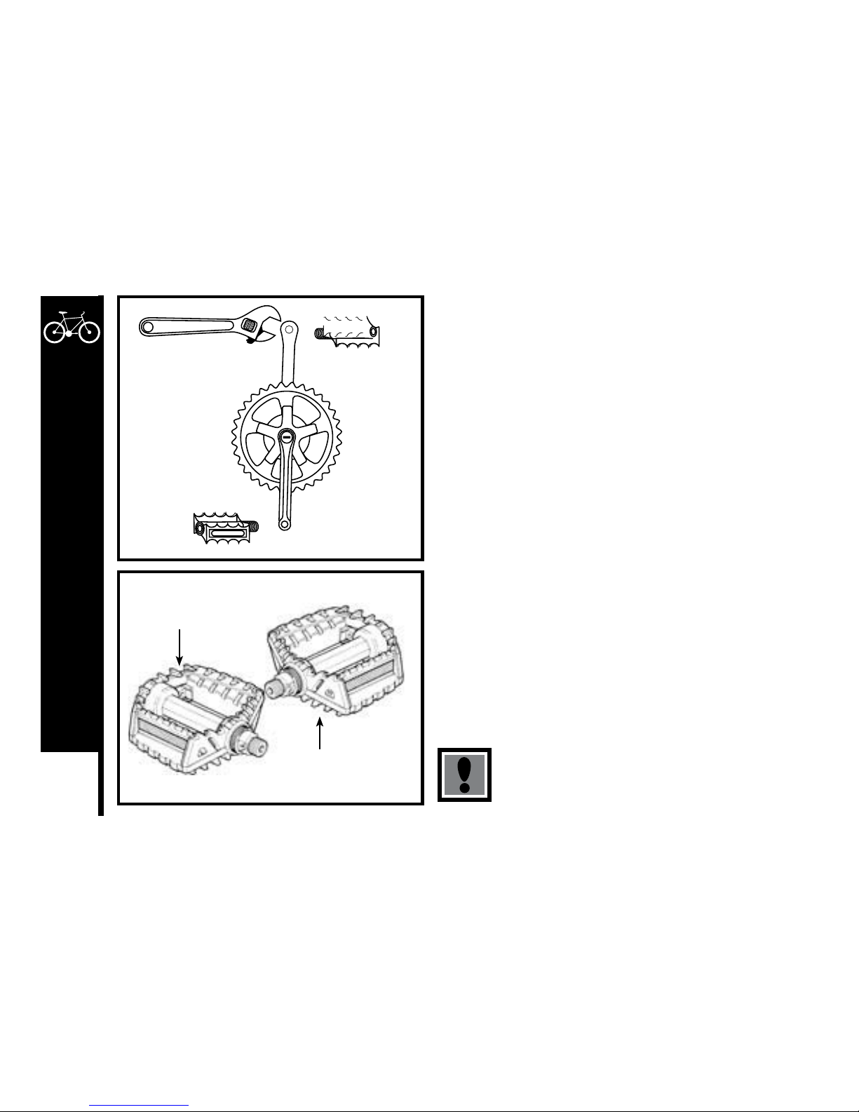
78
DETAILED MAINTENANCE
DRIVETRAIN
The drivetrain of a bicycle refers to all parts that transmit power to the
rear wheel including the pedals, chain, chainwheel, crank set, and
freewheel.
Pedals
Pedals are available in a variety of shapes, sizes and materials, and
each are designed with a particular purpose in mind. Some pedals
can be fitted with toe clips and straps. These help to keep the feet
correctly positioned and allow the rider to exert pulling force, as well as
downward pressure, on the pedals. Use of toe clip with straps requires
practice to acquire the necessary skill to operate them safely.
Inspection
Pedals should be inspected every month, taking note of the following
areas:
– Check correct tightness into the crank arms. If pedals are allowed
to become loose, they will not only be dangerous but will also cause
irreparable damage to the cranks.
– Check that pedal bearings are properly adjusted. Move the pedals
up and down, and right to left, and also rotate them by hand. If
you detect any looseness or roughness in the pedal bearings then
adjustment, lubrication or replacement is required.
– Ensure that the front and rear pedal reflectors are clean and
securely fitted.
– Also ensure that the toe clips, if fitted, are securely tightened to the
pedals.
Never ride with loose pedals.
L = Left
Turn counter-clockwise
to tighten.
R = Right
Turn clockwise
to tighten.
Meijer.com
Page 82
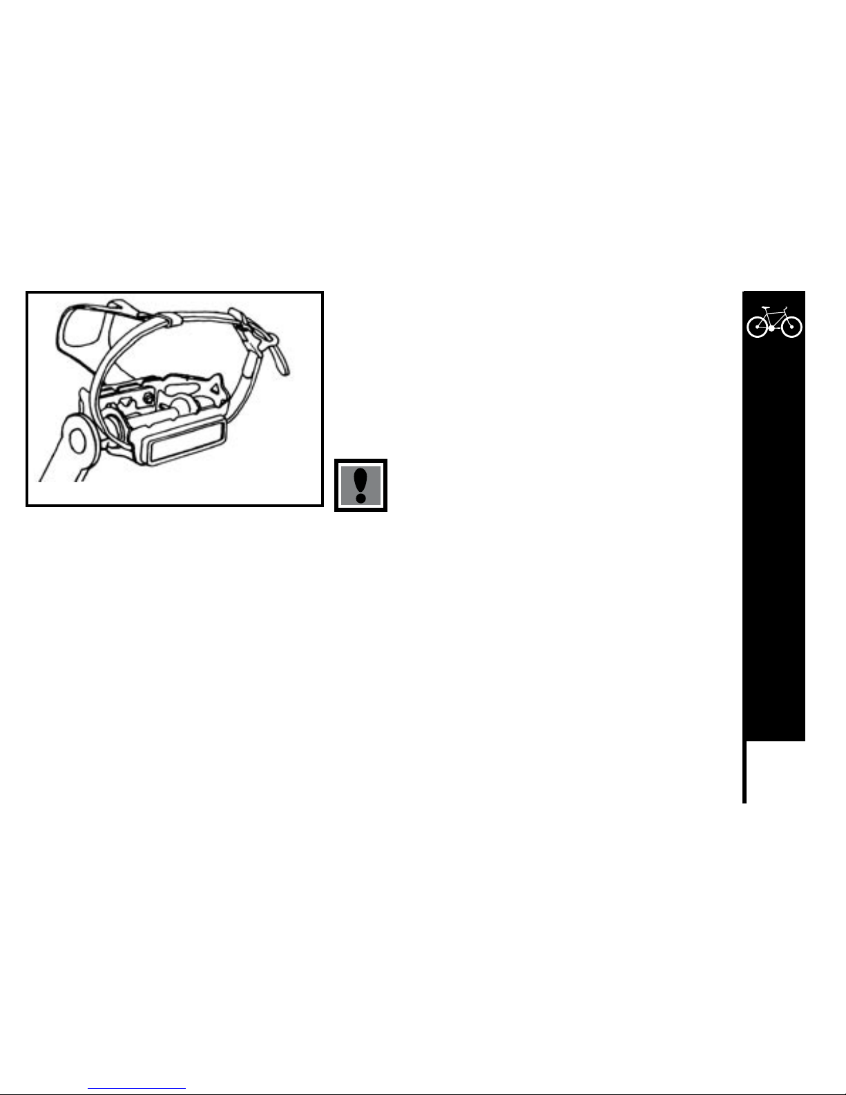
79
DETAILED MAINTENANCE
Lubrication and Adjustment
Many pedals cannot be disassembled to allow access to the internal
bearings and axle. However, it is usually possible to inject a little oil onto
the inside bearings, and this should be done every six months. If the pedal
is the type that can be fully disassembled, then the bearings should be
removed, cleaned and greased every six to twelve months. Because of
the wide variety of pedal types and their internal complexity, disassembly
procedures are beyond the scope of this manual and further assistance
should be sought from a specialist.
Never ride in traffic with fully tightened toe straps.
Attachment
Note: The right and left pedals of a bicycle each have a different thread and are not interchangeable.
Never force a pedal into the incorrect crank arm.
The right pedal, which attaches to the chainwheel side is marked ‘R’ on the end of the axle, and screws in with a clockwise thread. The
left pedal, which attaches to the other crank arm, is marked ‘L’ on the axle, and screws in with a counter-clockwise thread.
Insert the correct pedal into the crank arm and begin to turn the thread with your fingers only. When the axle is screwed all the way in,
securely tighten using a 15mm wrench.
If removing a pedal, remember that the right pedal axle must be turned counter clockwise, i.e. the reverse of when fitting.
If replacing the original pedals with a new set, make sure the size and the axle thread is compatible with the cranks on your bicycle.
Bicycle use one of two types of cranks and these use different axle threads. Your bike may be equipped with cranks that are a one piece
design with no separate axle. These operate with pedals that have a 1/2”(12.7mm) thread. Bikes equipped with three piece crank sets
with a separate axle, left crank and right crank, use a slightly larger 9/16”(14mm) thread.
Note: Never try and force a pedal with the wrong thread size into a bicycle crank.
Pedal with toe clip and strap attached
Meijer.com
Page 83
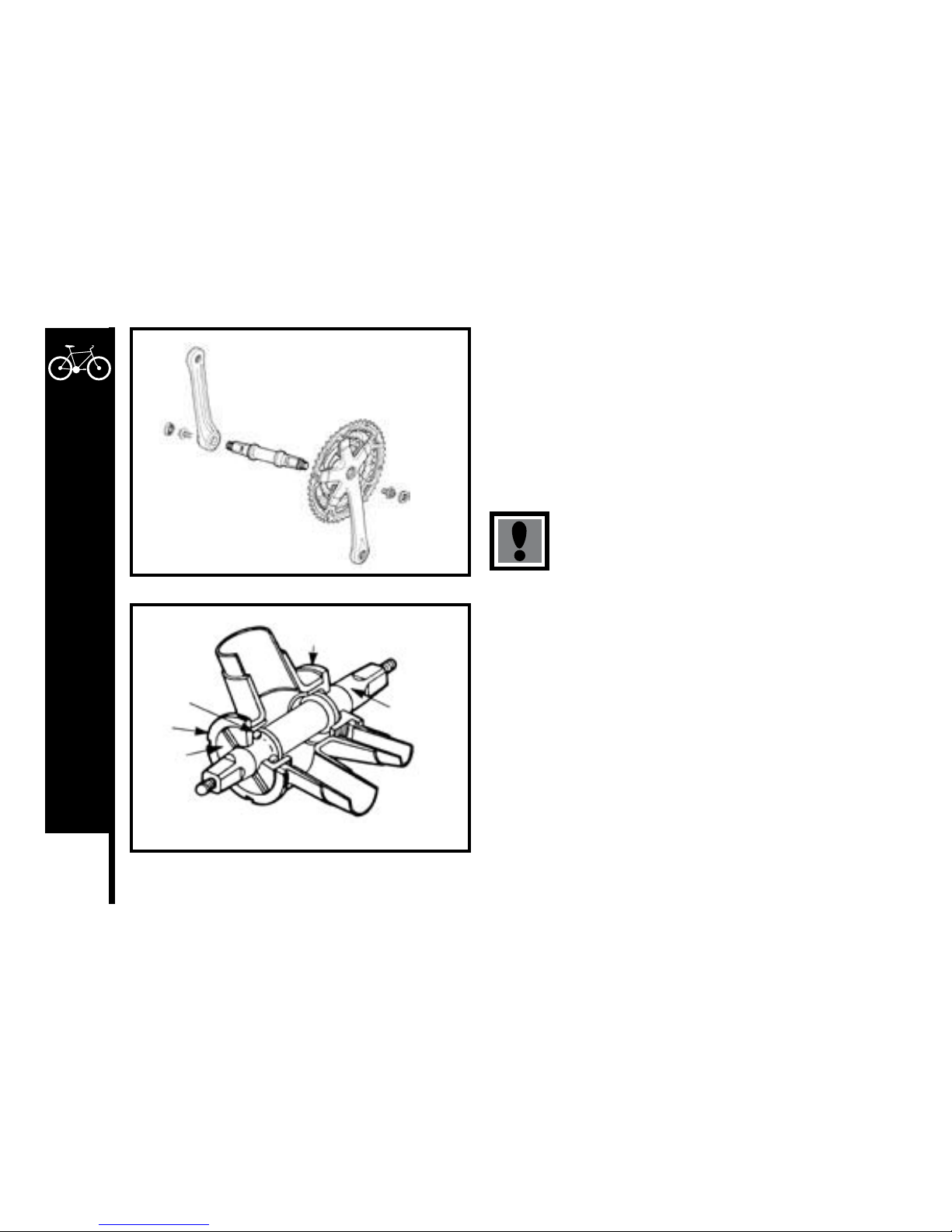
80
DETAILED MAINTENANCE
CRANK SET
The crank set refers to the bottom bracket axle and bearing, the crank
arms, and chainrings.
Your bike may be fitted with either a one piece crank, where the crank
arms and bottom bracket are single component, or cotterless cranks,
where the crank arms bolt onto the bottom bracket axle without using
old fashioned type cotterpins. The one piece system is simpler and
requires less maintenance, while the cotterless system requires a little
extra care.
Never ride your bike if the cotterless cranks are loose.
This may be dangerous and will damage the crank arms
beyond repair.
Inspection
The crank set should be checked for correct adjustment and tightness
every month. Cotterless crank axle nuts must be kept tight, and the
bottom bracket bearings must be properly adjusted. Remove the chain
and try to move the cranks from side to side with your hands. The
cranks should not move on the axle, and there should be only very
slight movement in the bottom bracket. Next, spin the cranks. If they
don’t spin freely without grinding noise, then adjustment or lubrication
will be needed. Also check that there are no broken teeth on the
chainrings, and wipe off excess dirt and grease that may have built up
on them.
Cotterless Crank
Fixed Cup
Ball Bearing
Lockring
Adjusting
Cup
Axle
Standard Bottom Bracket Assembly (Cotterless)
Meijer.com
Page 84
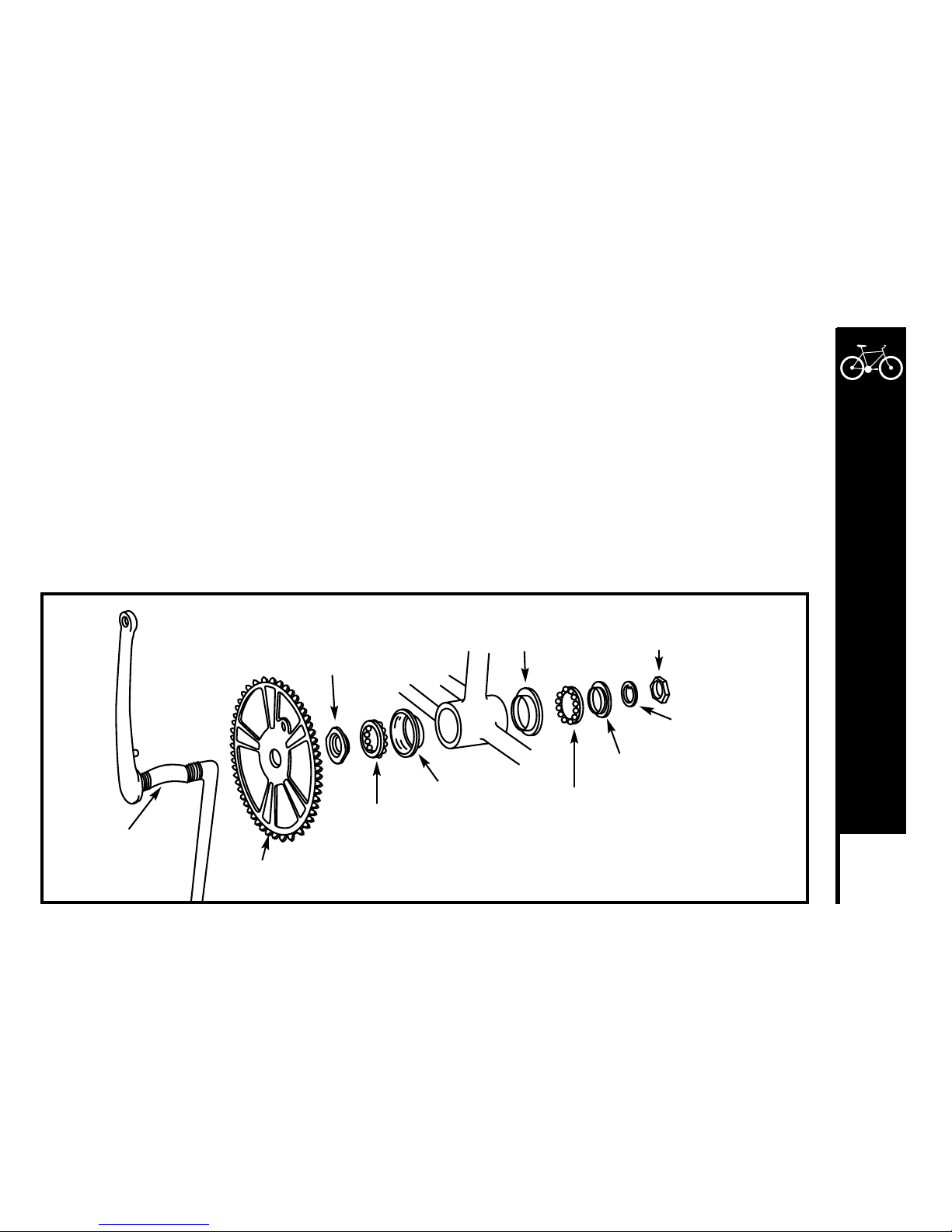
81
DETAILED MAINTENANCE
Lubrication and Adjustment – One Piece Cranks
To adjust the free play in a one piece type bottom bracket, loosen the locknut on the left side by turning in clockwise and tighten the
adjusting cone counter-clockwise using a screwdriver in the slot. When correctly adjusted, re-tighten the locknut counter-clockwise.
To disassemble:
1. Remove the chain from the chainwheel
2. Remove the left pedal by turning the spindle clockwise
3. Remove the left side locknut by turning it clockwise and remove the keyed lockwasher.
4. Remove the adjusting cone by turning it clockwise with a screwdriver.
5. Remove the left ball retainer, slide the crank assembly out of the frame to the right, and remove the right ball retainer.
Clean and inspect all bearing surfaces and ball retainers, and replace any damaged parts. Pack the ball bearing retainers with
grease, then re-assemble in the reverse of the above procedure.
One Piece Crank Assembly
Crank
Fixed Cone
Ball Retainer
Ball Retainer
Adjusting Cone
Chainwheel
Bearing Cup
Bearing Cup
Lockwasher
Locknut
Meijer.com
Page 85
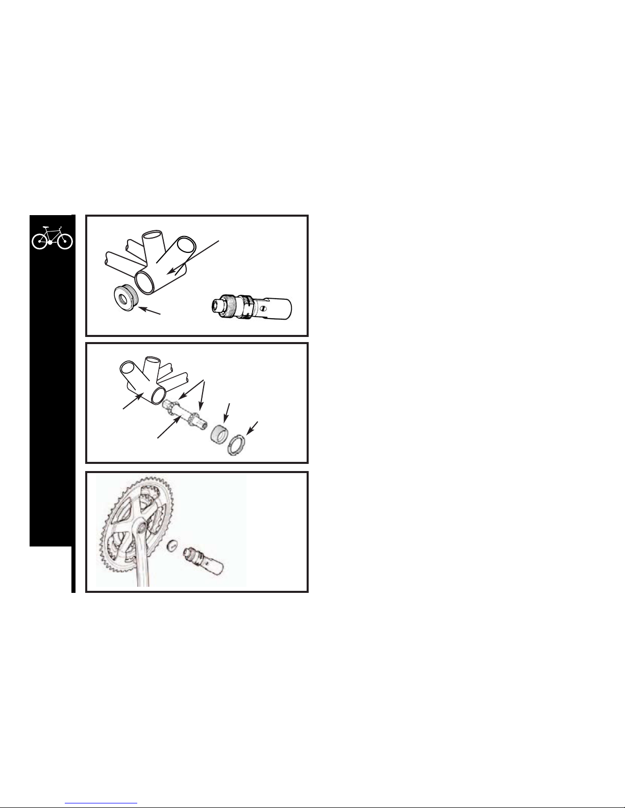
82
DETAILED MAINTENANCE
Lubrication and Adjustment – Cotterless Cranks
To adjust the free play in a three piece type bottom bracket, loosen the
lockring on the left side by turning in counter-clockwise, then turn the
adjusting cup as required. Re-tighten the lockring taking care not to alter
the cup adjustment.
To disassemble:
1. Remove the cranks from the axle.
2. Remove the left side lockring by turning it counter-clockwise.
3. Remove the adjusting cup by turning it counter-clockwise.
4. Remove the left ball retainer and slide the axle out of the frame to the
left.
5. Remove the right side fixed cup by turning it counter-clockwise and
remove the right ball retainer. Clean and inspect all bearing surfaces
and ball retainers, and replace any damaged parts. Pack the ball
bearing retainers with grease, then re-assemble in reverse of the
above procedure.
Cotterless Crank Removal
To remove cotterless cranks use the following procedure. Note that a
special tool will be required.
1. Remove the dust cap with a coin or screwdriver.
2. Loosen the flange nut or bolt and washer, and remove.
3. Screw the removing tool into the crank and tighten.
4. Turn the screw bolt down until the crank comes away from the axle.
Cotterless Crank Replacement:
1. Replace the crank arm onto the axle.
2. Tap the crank arm lightly with a mallet.
3. Refit the washer and tighten flange nut or bolt securely to a torque of
27Nm.
4. Replace the dust cover.
Fixed Cup
Bottom Bracket
Cotterless Crank removing tool
Ball Retainer
Axle
Adjusting Cup
Lockring
Bottom Bracket
Shell
Remove the dust cap.
Loosen and remove
the flange nut.
Meijer.com
Page 86
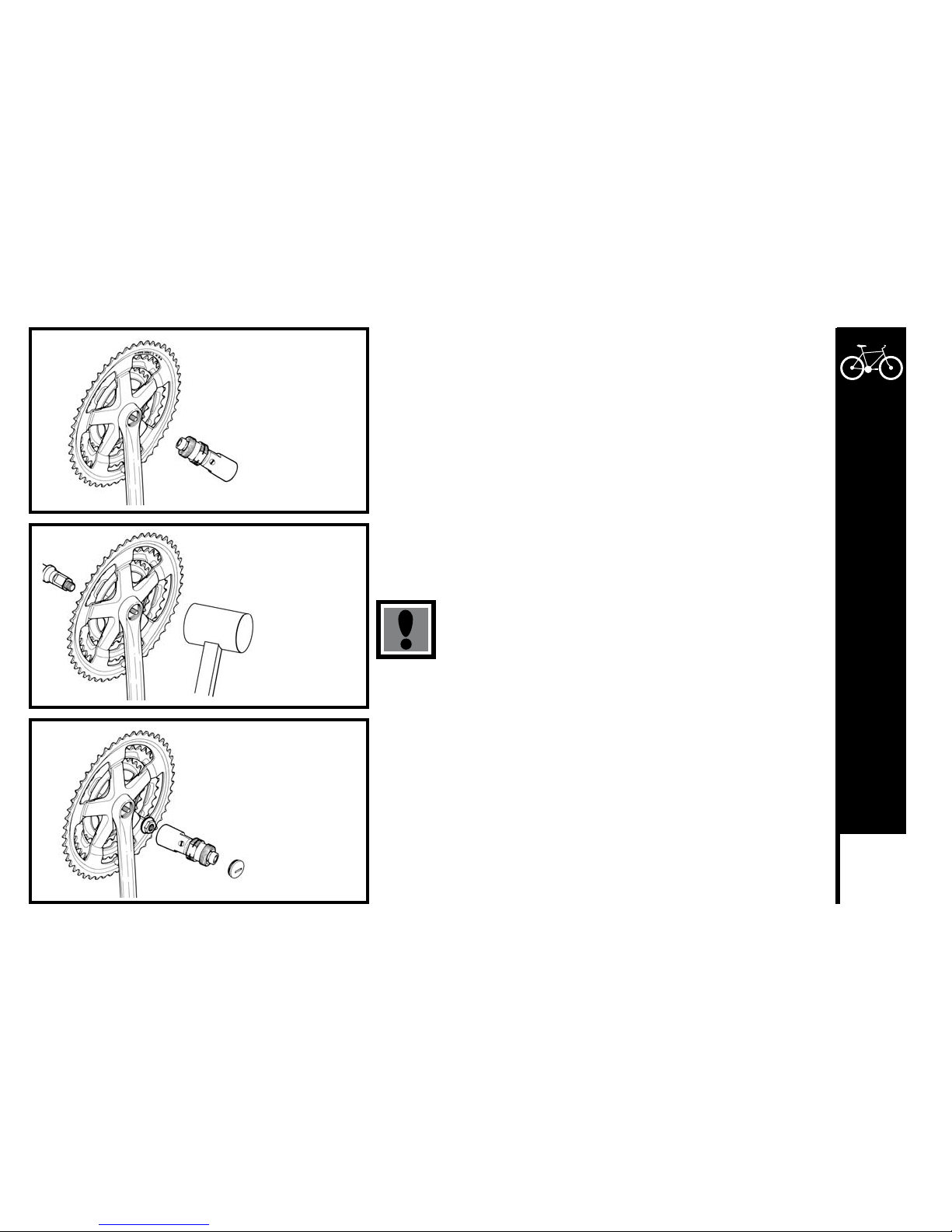
83
DETAILED MAINTENANCE
Adjustment After Use:
1. Remove dust cap.
2. Tap the crank arm lightly with a mallet.
3. Retighten the flange nuts, and refit the dust caps.
New cotterless cranks may become loose with initial use.
Perform the following task after several hours of riding,
and repeat it two or three times after further use. Cranks
should then remain tight.
Screw in the removal tool.
Turn the screw bolt
clockwise.
Position the crank on the axle.
Lightly tap the crank
onto the axle.
Tighten the flange nut.
Replace the dust cap.
Meijer.com
Page 87
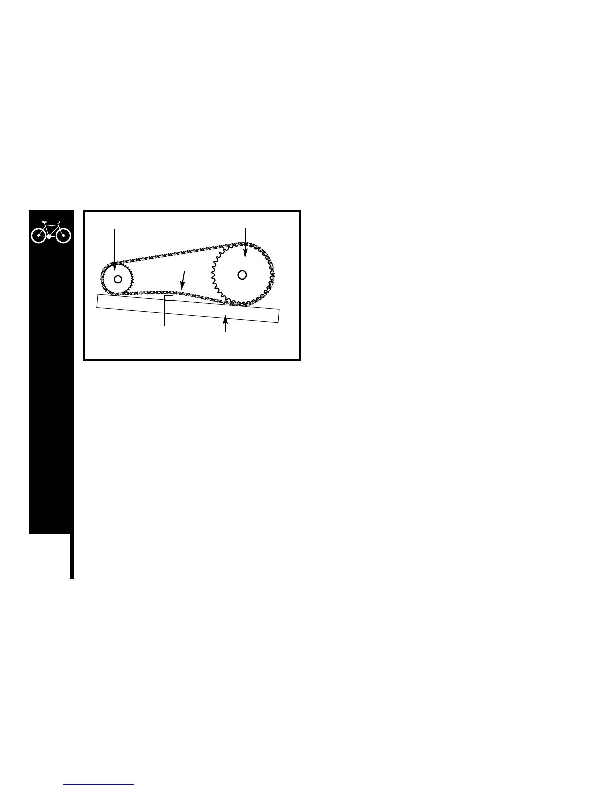
84
DETAILED MAINTENANCE
Chain
Inspection
The chain must be kept clean, rust fee and frequently lubricated in
order to extend its life as long as possible. It will require replacement if
the stretches, breaks, or causes inefficient gear shifting. Make sure that
there are no stiff links, the must all move freely.
Lubrication
The chain should be lubricated with light oil at least every month, or after use in wet, muddy, or dusty conditions. Take care to wipe off
excess oil, and not to get oil on the tires or rim braking surfaces.
Adjustment and Replacement
On derailleur geared bicycle the rear derailleur automatically tensions the chain.
To adjust the chain on single speed freewheel, coaster hub brake or 3-speed hub geared bicycles:
1. Loosen the rear axle nuts (and coaster brake arm clip if fitted) and move the wheel forward to loosen, or backward to tighten, in the
frame.
2. When correctly adjusted, the chain should have approximately 10mm of vertical movement when checked in the center between the
chainwheel and rear sprocket. Center the wheel in the frame and re-tighten the axle nuts after any adjustment. Bicycle that have a
single speed freewheel, coaster hub brake or 3-speed hub, generally use a wider type chain than derailleur-geared bicycles. These
chains can be disconnected by way of a special U-shape joining link that can be pried off of the master link with a screwdriver.
To replace, feed the chain around the chainwheel and rear sprocket, fit the master link into the rollers into each end of the chain,
position the master link side plate, and slip on the U-shaped snap-on plate. Make sure the open end of the U-shaped plate is trailing
as the link approaches the chainwheel when pedaling forward.
Straightedge
10 mm
Rear Sprocket Front Chainwheel
Pull up
Meijer.com
Page 88
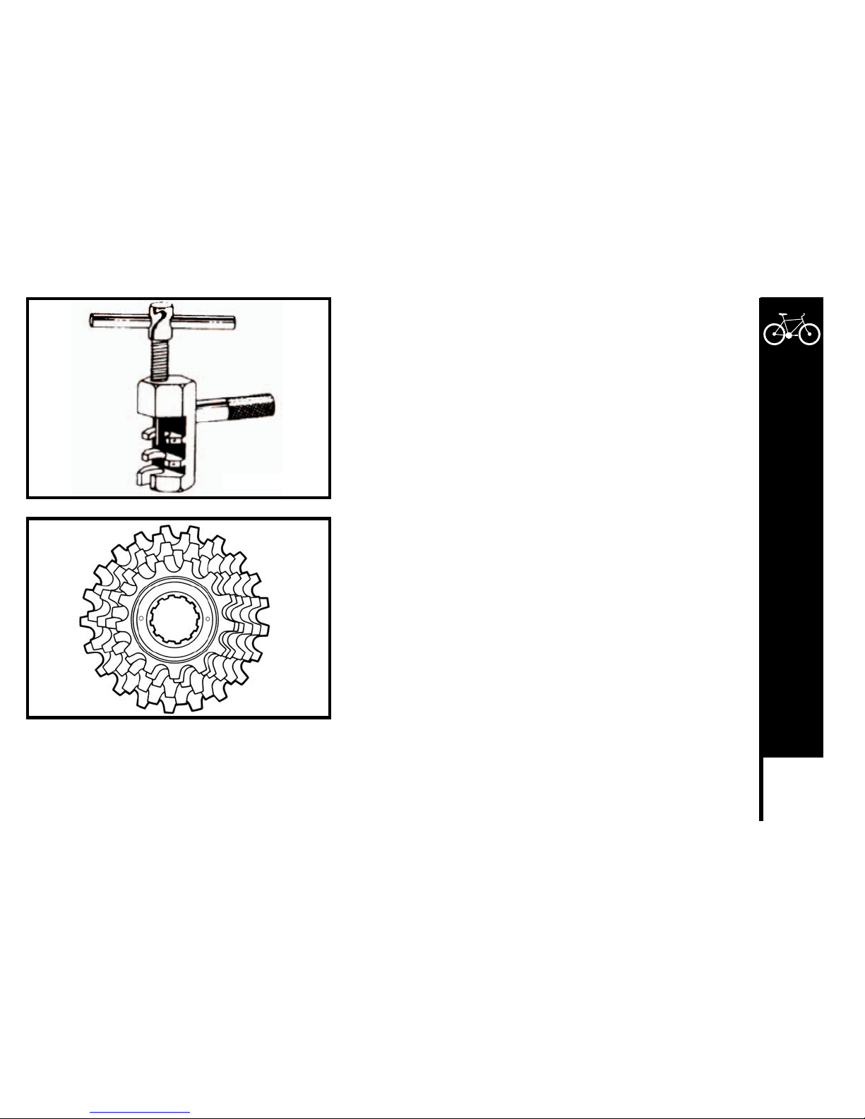
85
DETAILED MAINTENANCE
Derailleur geared bicycles use narrower chains and require a special tool to
fit and remove chain links, or to change the length. To remove, fit the rivet
tool so that the punch pin is centered over any one of the chain rivets. Push
the rivet almost all the way out, then back out the punch and remove the
tool. Holding the chain on both sides of the punched rivet, bend it slightly
to release link from the rivet. To install, feed chain around chainwheel, rear
sprocket and derailleur cage with rivet facing away from the bicycle. Bring the
two ends together within the special tool and punch the rivets into place. Be
sure not to push rivet too far through side plate.
FREEWHEEL
Inspection
Like the chain, the freewheel must be kept clean and well lubricated. If
the chain has become worn and needs replacing, then it is likely that the
freewheel will also have become worn and should also be replaced. Take
the chain off the freewheel and rotate it with your hand. If you hear a
grinding noise or the freewheel stops suddenly after spinning it, it may need
adjustment or replacement. Such action is beyond the scope of this manual
and you should consult a specialist.
Chain Rivet Tool
Meijer.com
Page 89
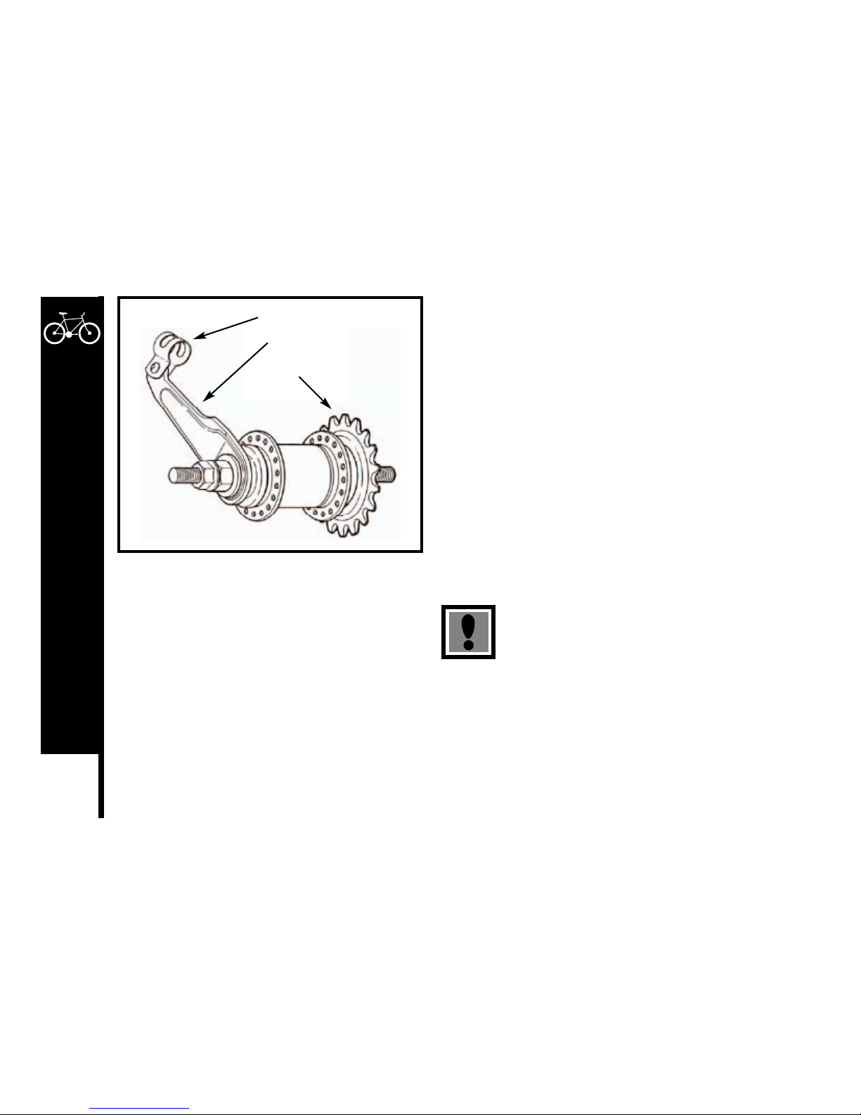
86
DETAILED MAINTENANCE
Lubrication
Remove any accumulated dirt from the freewheel with a brush and a
degreaser. Disassembly of the freewheel is a complicated procedure
requiring special tools, and should be left to a specialist. Apply oil to the
freewheel whenever you lubricate that chain, taking care to wipe off any
excess.
COASTER HUB
Many BMX style and other children’s bicycles are fitted with a coaster
hub brake in the rear wheel. This type of brake offers the advantages
of reliability and easy operation. The brake is operated by applying back
pedal pressure and allows the rider the ‘coast’ without pedaling, if desired.
There are several models of coaster hubs available, and the internal
mechanisms are very complex. They require infrequent attention as far
as lubrication, adjustment or replacement of internal parts; if needed, this
should be left to a specialist.
Keep the coaster hub sprocket clean and oil it along with the chain.
Make sure the brake arm is correctly attached to the
chainstay with the brake arm clip. The brake will not
operate otherwise.
Brake Arm Clip
Brake Arm
Sprocket
Meijer.com
Page 90
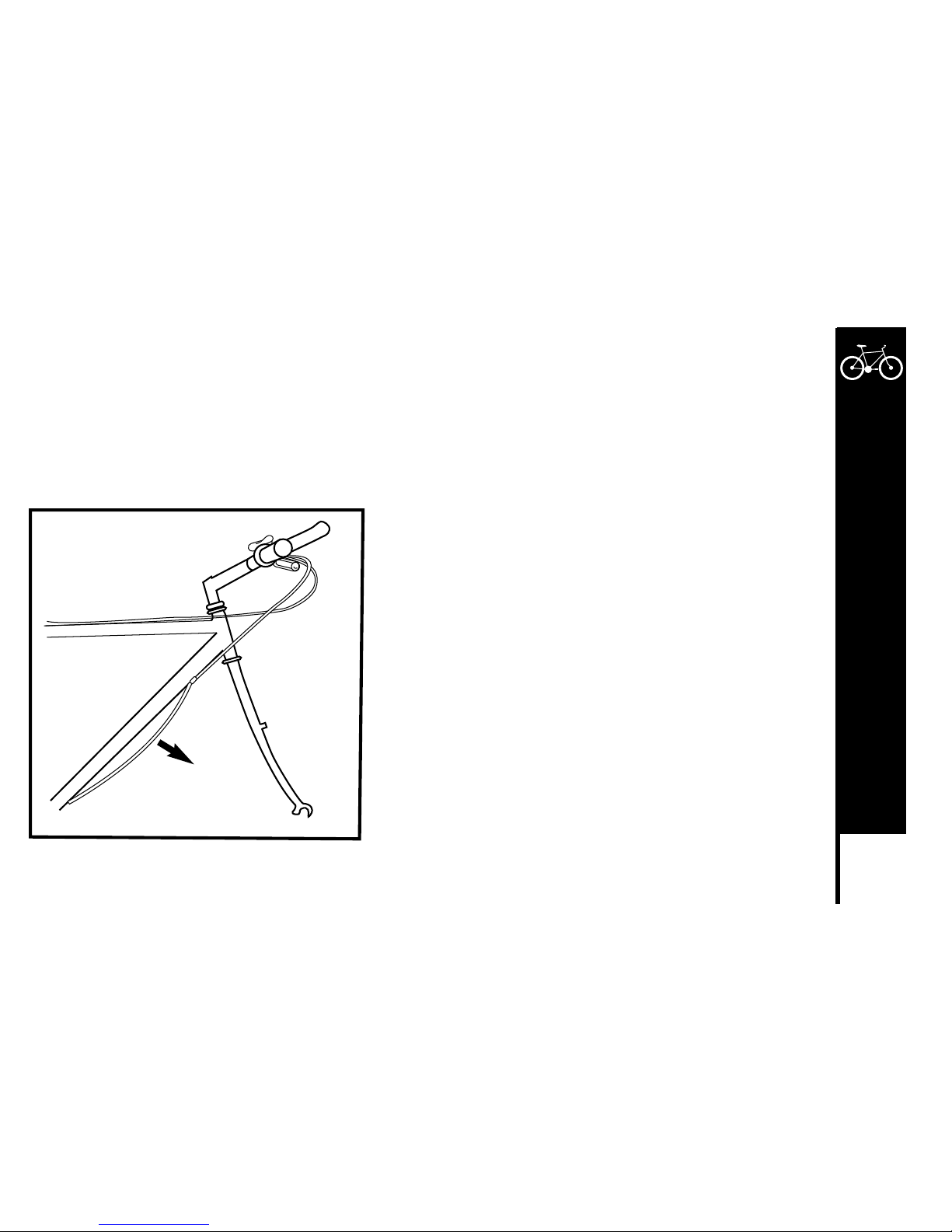
87
DETAILED MAINTENANCE
DERAILLEUR SYSTEMS
The derailleur system includes the front and rear derailleurs, the shift levers, and the derailleur control cables, all of which must function
correctly for smooth gear shifting to occur. There are several different types of derailleur systems but all operate using similar principles.
Your new bicycle may be fitted with a standard ‘friction’ type system where you will need to feel each gear shift into position. It may be
fitted with an ‘index’ system (e.g. SIS) which links each different gear position to a positive click mechanism in the shifter,
and makes shifting very simple and precise. A further development of SIS is the fully integrated system (e.g. STI) where the shift
lever and brake lever mechanisms form an integrated unit with the system allowing both gear shifting and braking to occur at the same
time.
Inspection
The operation of the derailleur system should be checked at least every
month. Check the operation of the rear derailleur first, then the front. The
rear derailleur should shift the chain cleanly from on cog to the next without
hesitation. On SIS equipped bicycles, each notched position in the shifter
must equate to a new gear position. After shifting, the rear derailleur should
not rub on the chain. The derailleur should never cause the chain to fall off
the inner or outer freewheel cogs.
The front derailleur should also shift the chain cleanly and if equipped with
front SIS, then each click or stop in the shifter should equate exactly to
a new gear position. When the chain has been positioned onto a new
chainring, it should not rub on the front derailleur. The chain should not fall
off a chainring at any time. Derailleur control cables are a critical component
that must be well maintained for accurate shifting performance.
Check them for any sign of rust, fraying, kinks, broken strands, and any
damage to the cable housing. If you find any problems, the cables may need
replacing before you ride.
Pre-stretch the derailleur
cables to remove slack
Stretch
Meijer.com
Page 91
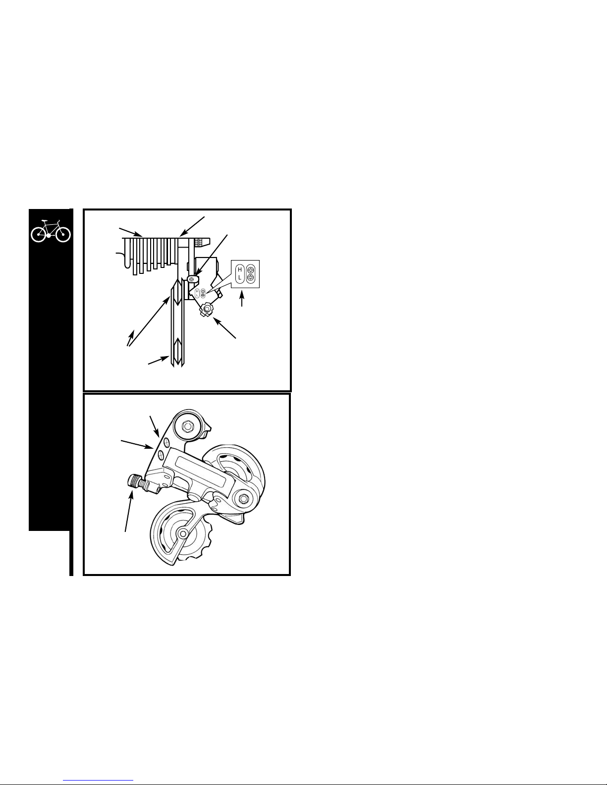
88
DETAILED MAINTENANCE
Lubrication
All the pivoting points of the front and rear derailleurs should be lubricated
with light oil at least every month. Be sure to wipe off any excess oil to
prevent attraction of dirt into the mechanisms. The shifting cables should
be cleaned and re-coated with a thin layer of grease every six months, or
whenever new cables are being installed.
Adjustment – Rear Derailleur
The Low limit screw determines how far the rear derailleur will travel
toward the wheel of the bicycle, while the High limit screw determines how
far the cage will travel toward the frame.
1. Shift the rear shifter to the largest number indicated, disconnect the
rear derailleur cable from the cable anchor bolt and place the chain on
the smallest sprocket.
2. Adjust the High limit screw so that chain and the smallest sprocket
are lined up vertically. Remove any slack in the cable by pulling it taut,
then re-connect the cable and tighten the cable anchor bolt securely.
3. Shift up through the gears makes sure that each gear is achieved
quietly and without hesitation.
If noise occurs, use the barrel adjuster to fine-tune the cable tension.
Turning the barrel adjuster clockwise will decrease cable tension and
allow the derailleur cage to move farther away from the bicycle in
small increments. Turning counter-clockwise will increase cable
tension and bring the cage closer to the bicycle. This will micro-adjust
the positioning of the derailleur cage in relation to the freewheel.
4. Shift the chain onto the largest sprocket; adjust the low limit screw so
the chain and the largest cog are lined up vertically. If you are unable
to get the chain and the largest cog, turning the Low limit screw
counter-clockwise will enable the chain to move towards the wheel.
5. Shift through the gears ensuring each gear is achieved quietly and
without hesitation.
NOTE: It may take several adjustments to achieve the desired positioning.
Please refer to the troubleshooting section for more assistance.
Rear Derailleur Rear View
Freewheel
SIS Cable Adjuster
Outer side of Top Gear
Pulley Adjustment
Screw
Guide Pulley
Tension Pulley
Adjustment
Screws
Rear Derailleur Side View
SIS Cable
Adjuster
High Gear
Adjustment Screw
Low Gear
Adjustment Screw
Meijer.com
Page 92
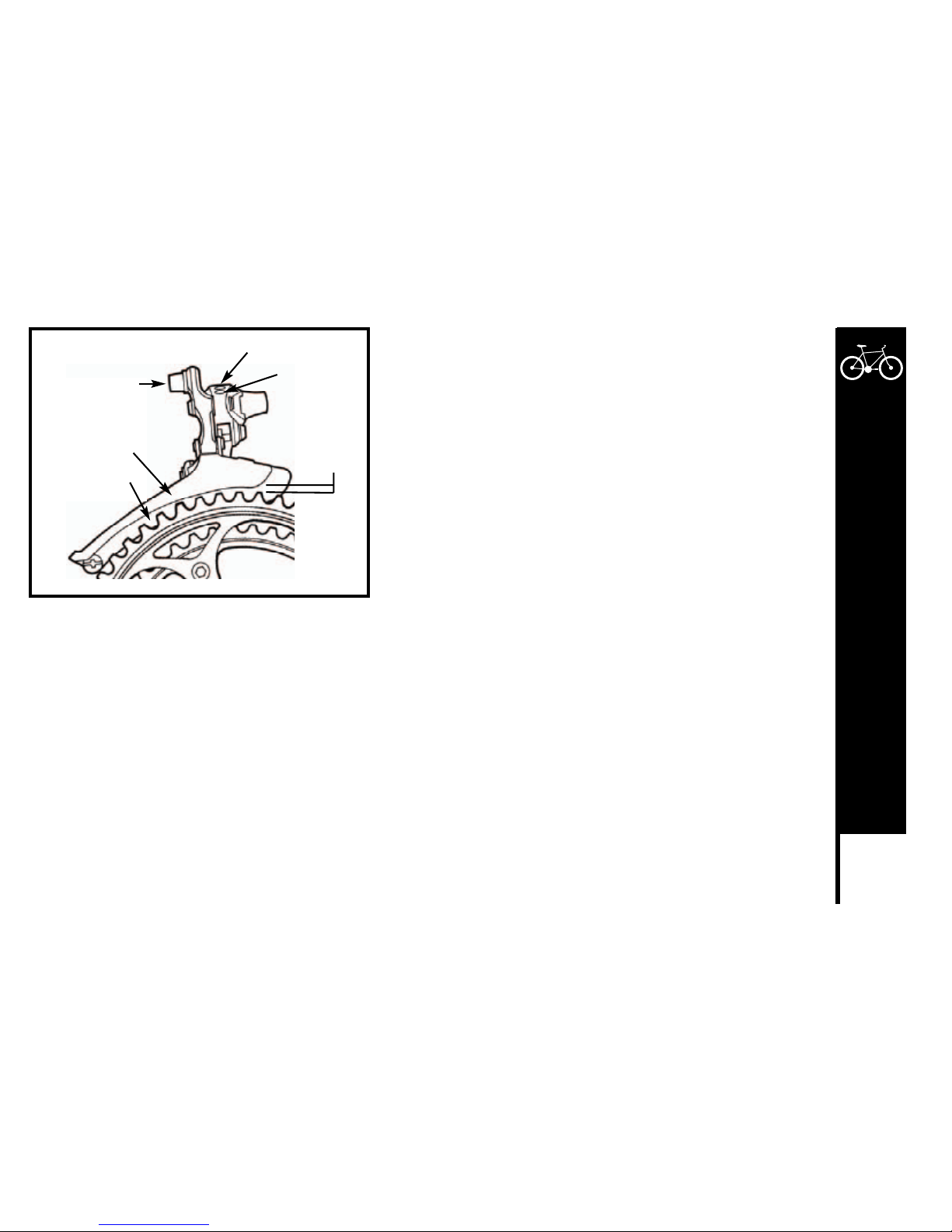
89
DETAILED MAINTENANCE
Adjustment – Front Derailleur
1. Shift the rear shifter to the smallest number indicated, then shift the front
shifter to the smallest number indicated. Disconnect the front derailleur
cable from the cable anchor bolt and place the chain on the smallest
chainwheel.
2. Make sure the front derailleur cage is parallel with the outer chainwheel
on the crankset. There must be a 3-5mm gap between the bottom of the
derailleur cage and the top of the outer chainwheel teeth to ensure the
derailleur will clear the chainwheel when shifting.
3. Adjust the low limit screw so the chain is centered in the middle of
derailleur cage. Pull all slack out of the cable by pulling it taut, then
reconnect the cable and tighten the cable anchor bolt securely.
4. Shift the front shifter into the largest gear and pedal the bike so the chain
jumps to the largest chainwheel. If the chain does not shift onto the
largest chainwheel, you will need to turn the High limit screw counterclockwise until the chain moves to the largest chainwheel. If the chain
falls into the pedals, the High limit screw has been tuned too far. You will
need to readjust the High screw clockwise in 1/4 turn increments until the
chain no longer falls off.
5. Shift through each gear ensuring all are achieved quietly and without
hesitation.
6. The barrel adjuster for the front derailleur is located on the shift
mechanism. Turning clockwise will decrease cable tension and allow the
front derailleur cage to move away from the bike, while turning counterclockwise will increase tension and bring the cage closer to the bike. If
you are experiencing problems shifting between gears, use the barrel
adjuster to fine-tune the cable tension.
NOTE: It may take several adjustments to achieve the desired positioning.
Cable Fixing Bolt
Outer Chainguide
Inner Chainguide
Low Adjusting Screw
High Adjusting
Screw
Chainguide
clearance of
1-3 mm
Meijer.com
Page 93
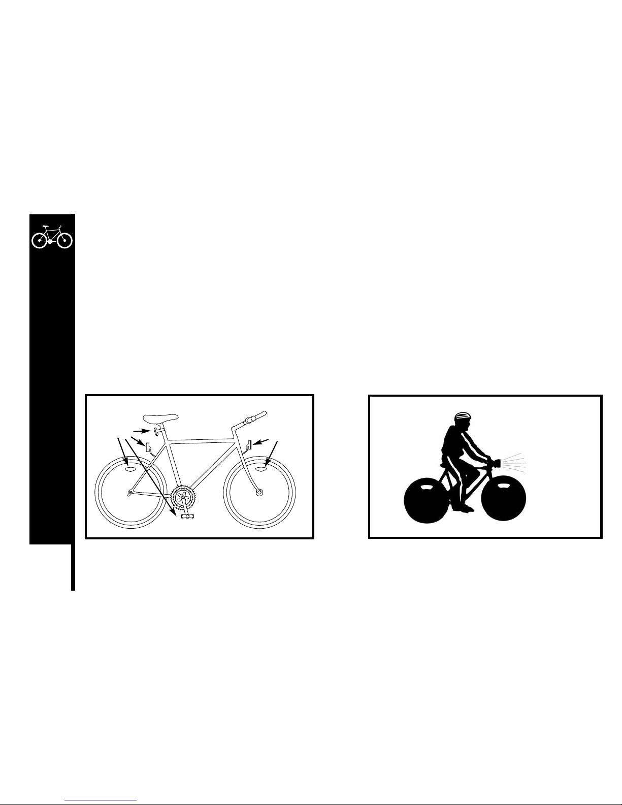
90
DETAILED MAINTENANCE
QUICK RELEASE LEVERS
It is important to check the quick release levers before every ride to ensure all connections are made properly and securely. Periodically,
disassemble the mechanism from the bicycle and inspect for any wear or damage and replace if necessary. When re-installing, it is very
important to ensure the connections are made properly. Please refer to page 29 and 30 for the appropriate assembly instructions.
REFLECTORS
Your bicycle is supplied with one front (white), one rear (red), two wheel (white), and two pedal (orange) reflectors. These are an
important safety and legal requirement, and should remain securely fitted and in good, clean conditions at all times. Periodically, inspect
all reflectors, brackets and mounting hardware for signs of wear or damage. Replace immediately if damage is found.
Reflectors
Reflectors
Wear reflective clothing
when riding.
Attach a light to your
bike if you ride at night.
Meijer.com
Page 94
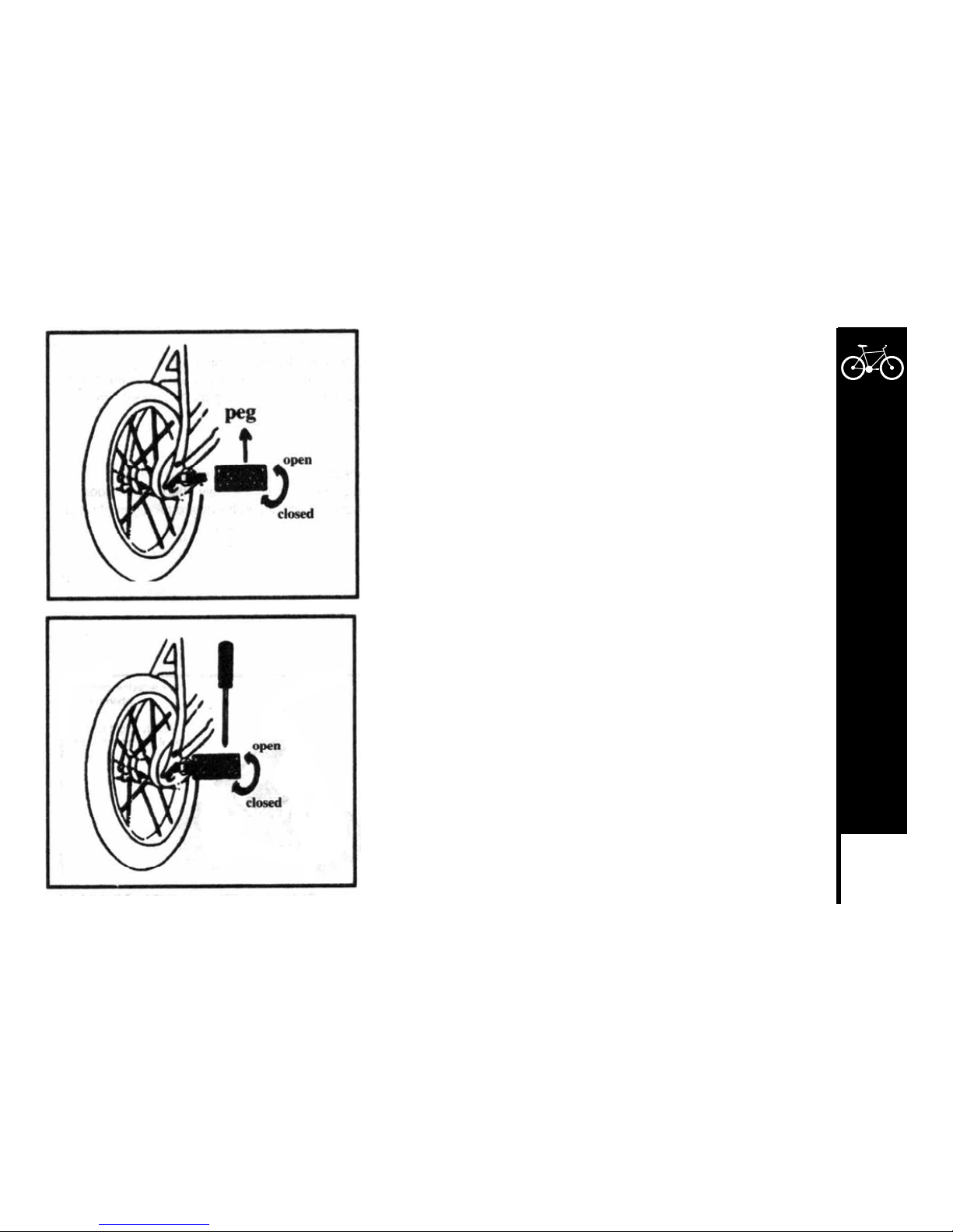
91
DETAILED MAINTENANCE
Peg Setting
Install peg on axle and use a screw driver to tighten peg securely.
Meijer.com
Page 95
92
DETAILED MAINTENANCE
Problem Possible Cause Remedy
Gear shifts not working properly - Derailleur cables sticking/stretched/
damaged
- Lubricate/tighten/replace cables
- Front or rear derailleur not adjusted
properly
- Adjust derailleurs
- Indexed shifting not adjusted properly - Adjust indexing
Slipping chain - Excessively worn/chipped chainring or
freewheel sprocket teeth
- Replace chainring, sprockets and
chain
- Chain worn/stretched - Replace chain
- Stiff link in chain - Lubricate or replace link
- Non compatible chain/chainring/
freewheel
- Seek advice at a bicycle shop
Chain jumping off freewheel sprocket or
chainring
- Chainring out of true - Re-true if possible, or replace
- Chainring loose - Tighten mounting bolts
- Chainring teeth bent or broken - Repair or replace chainring/set
- Rear or front derailleur side-to-side
travel out of adjustment
- Adjust derailleur travel
Contatnt clicking noises when pedaling - Stiff chain link - Lubricate chain/Adjust chain link
- Loose pedal axle/bearings - Adjust bearings/axle nut
- Bent bottom bracket or pedal axle - Replace bottom bracket axle or pedals
- Loose crankset - Tighten crank bolts
Grinding noice when pedaling - Pedal bearings too tight - Adjust bearings
- Bottom bracket too tight - Adjust bearings
- Chain fouling derailleurs - Adjust chain line
- Derailleur jockey wheels dirty/binding - Clean and lubricate jockey wheels
Meijer.com
Page 96
93
DETAILED MAINTENANCE
Problem Possible Cause Remedy
Freewheel does not rotate - Freewheel internal pawl pins are
jammed
- Lubricate. If problem persists, replace
freehweel
Brakes not working ef
fectively - Brake blocks worn down -
Replace brake blocks
- Brake blocks/rim greasy, wet or dirty - Clean blocks and rim
- Brake cables are binding/stretched/
damaged
- Clean/adjust/replace cables
-
Brake levers are binding - Adjust brake levers
- Brakes out of adjustment - Center brakes
When applying the brakes they squeal/
squeak
- Brake blocks worn down -
Replace blocks
- Brake block toe-in incorrect - Correct block toe-in
- Brake blocks/rim dirty or wet - Clean blocks and rim
- Brake arms loose - Tighten mounting bolts
Knocking or shudderin when applying
brakes
- Bulge in the rim or rim out of true
- True wheel or take to a bike shop for
repair
- Brake mounting bolts loose - Tighten bolts
- Brakes out of adjustment - Center brakes and/or adjust brake
block toe-in
- Fork loose in head tube -
Tighten headset
Wobbling wheel - Axle broken -
Replace axle
- Wheel out of true - True Wheel
- Hub comes loose - Adjust hub bearings
- Headset binding - Adjust headset
- Hub bearings collapsed - Replace bearings
Meijer.com
Page 97
94
DETAILED MAINTENANCE
Problem Possible Cause Remedy
Steering not accurate - Wheels not aligned in frame
- Align wheels correctly
- Headset loose or binding - Adjust/tighten headset
- Front forks or frame bent - Take bike to a bike shop for possible
frame realignment
Frequent punctures - Inner tube old or faulty -
Replace inner tube
- Tire tread/casing worn - Replace tire
- Tire unsuited to rim - Replace with correct tire
- Tire not checked after previous
puncture
- Remove sharp object embedded in tire
-
Tire pressure too low - Correct tire pressure
- Spoke protruding into rim - File down spoke
Meijer.com
Page 98
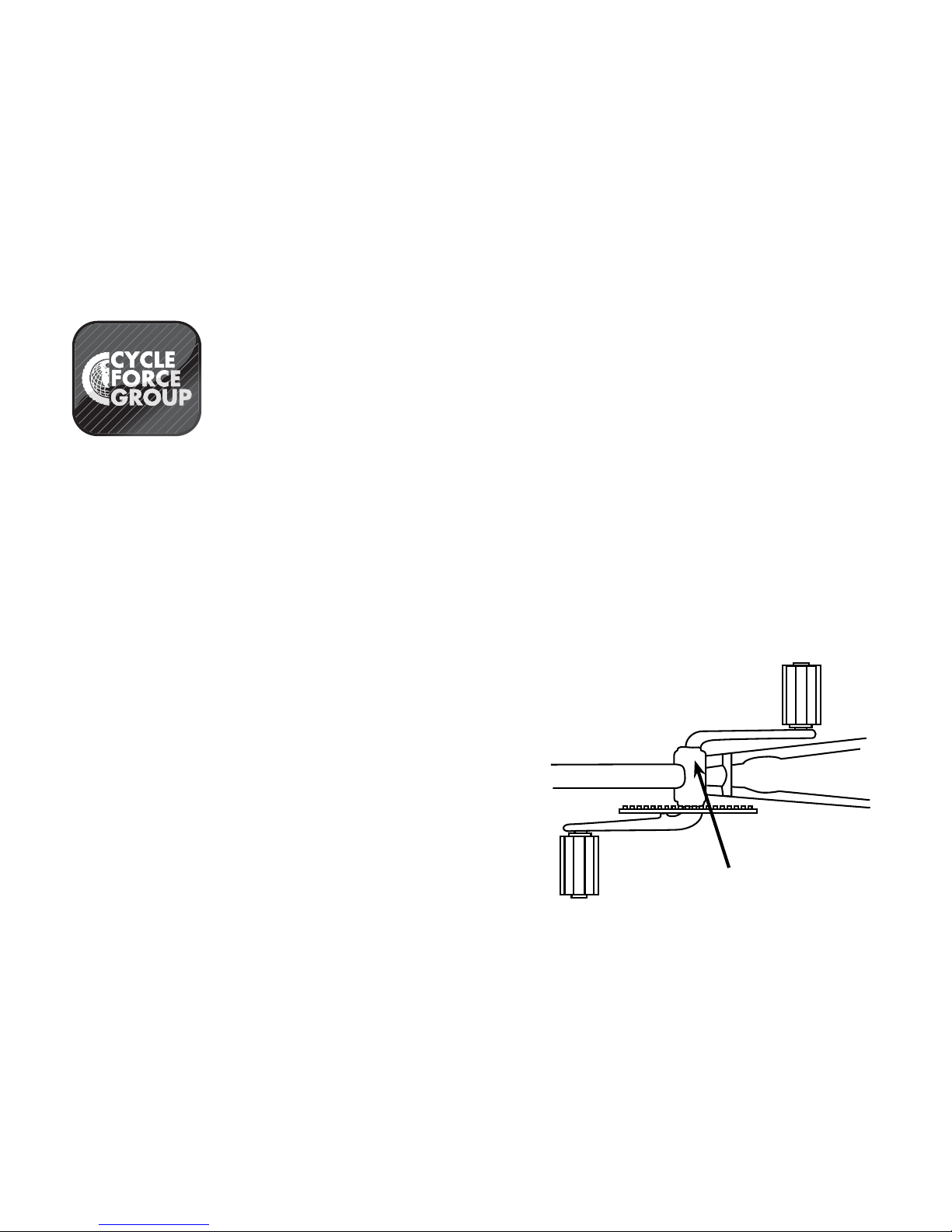
Purchase Record Card
Fill in Immediately and retain as a record of your purchase.
*Please retain your sales receipt for any possible warranty claims.
Your Name: ____________________________________________________________________________________________________________
Address: ______________________________________________________________________________________________________________
Date Purchased: _________________________________________Place of Purchase ________________________________________________
Model Name: __________________________________________________________________________________________________________
Wheel Size: ____________________________________________
Color: _________________________________________________
Serial Number: __________________________________________
####
Serial Number Location
Bike Shown Upside Down
Serial Number
You can also register your bicycle with
Cycle Force Group at www.cyclefg.com
Meijer.com
Page 99
Cycle Force Group warranties its bicycles to the original purchaser to be free from defects in
material and in workmanship for a period from the date of purchase of:
Lifetime on frame and fork as long as the bicycle is owned by the original owner except for the
specific models noted below:
– downhill – jumping –freestyle
– suspension related equipment (bushings, bearings, pivot pins, pivot tubes and bolts)
including complete forks except as warranted by the original equipment manufacturer.
One year on all original parts except for tires, tube and cables.
What Cycle Force Group will do:
In the event of a defective bicycle part, Cycle Force Group will, at its option, repair or replace
the defective bicycle or part within warranty period, at no cost to you except for shipping and
dealer charges if any. If you discover a defect within the warranty period, you must follow this
procedure:
A) Bring the bicycle to the original dealer from whom it was purchased. If the dealer from
whom you purchased this bicycle determines upon examination that either a repair or
replacement is justified and such determination is verified by Cycle Force Group, repair
or replacement will be made in accordance with the warranty.
B) When making claim under warranty, you must also bring to the original selling dealer a
copy of the sales receipt or proof of original purchase.
C) If the foregoing is not possible, write for assistance to:
Cycle Force Group
2105 SE 5th Street
Ames Iowa 50010
In your letter, state your full name and address and the reason why you believe there is a
defect in your bicycle, and inform Cycle Force Group of the date and under what conditions
the defect was discovered. Be sure to include a copy of the sales slip or other proof of
purchase.
D) Upon receipt and inspection of the bicycle by your Cycle Force Group dealer, the dealer
may determine that this warranty does not apply, in which case, you will be so notified
with a reason stated along with an estimate for repairs and return shipping. In no case
will Cycle Force Group be responsible for loss or damage in transit. You may advise the
dealer to repair or return the bicycle to you charges and shipping collect.
If you fail to pay the charges or leave the bicycle at the dealer for more than 60 days, the
dealer may at his/her discretion, dispose of the bicycle as he/she sees fit without liability
to you.
Limitation, exclusions, and other rights
A) This warranty does not cover tires, tubes, or any failure due to accident, abuse, misuse,
or neglect, or as a result of normal wear and tear.
B) The sole responsibility of Cycle Force Group pursuant to the terms of this warranty is
any, shall be repair and replacement.
C) The liability of Cycle Force Group shall in no event, exceed the original purchase or
incidental damages of any nature, including for example, but not by any way of limitation
damages for personal injuries or damages to property. This statement constitutes the
exclusive expression of warranty by Cycle Force Group and is in lieu of any and all
other warranties, written or implied.
D) No modifications of this warranty are authorized. There are no promises, terms,
conditions, or warranties other than those contained herein.
E) Some states do not allow limitations of incidental or consequential damages, so the
above limitations of exclusion may not apply to you.
F) This warranty gives you specific legal rights, and you may also have other rights, which
vary, from state to state.
Do not alter or use bicycle manufactured by Cycle Force Group in stunt riding, dirt riding,
similar activities, or with motors or power driven assists as power driven vehicles. Do not
operate bicycles manufactured by Cycle Force Group with multiple riders or tow another
person or vehicle. Any of the foregoing will invalidate the warranty and Cycle Force Group
shall not be liable for any failure, loss damage, or injury resulting form such uses and/or
alterations.
The descriptions and specifications contained in this manual were effective at the time of
printing. Cycle Force Group reserves the right to discontinue any model at any time and
change specifications or designs without notice.
Cycle Force Group
2105 SE 5th Street
Ames Iowa 50010
FOR SERVICE OR TECHNICAL HELP
CALL TOLL FREE:
(877) 245-3243
CYCLE FORCE GROUP LIMITED WARRANTY
Meijer.com
Page 100
www.cyclefg.com
Meijer.com
 Loading...