

Page 1
AlterPath™ OnBoard
QuickStart Guide
This guide provides a summary of basic AlterPath™ OnBoard installation tasks for expert administrators
who already know how to install and configure Cyclades AlterPath products.
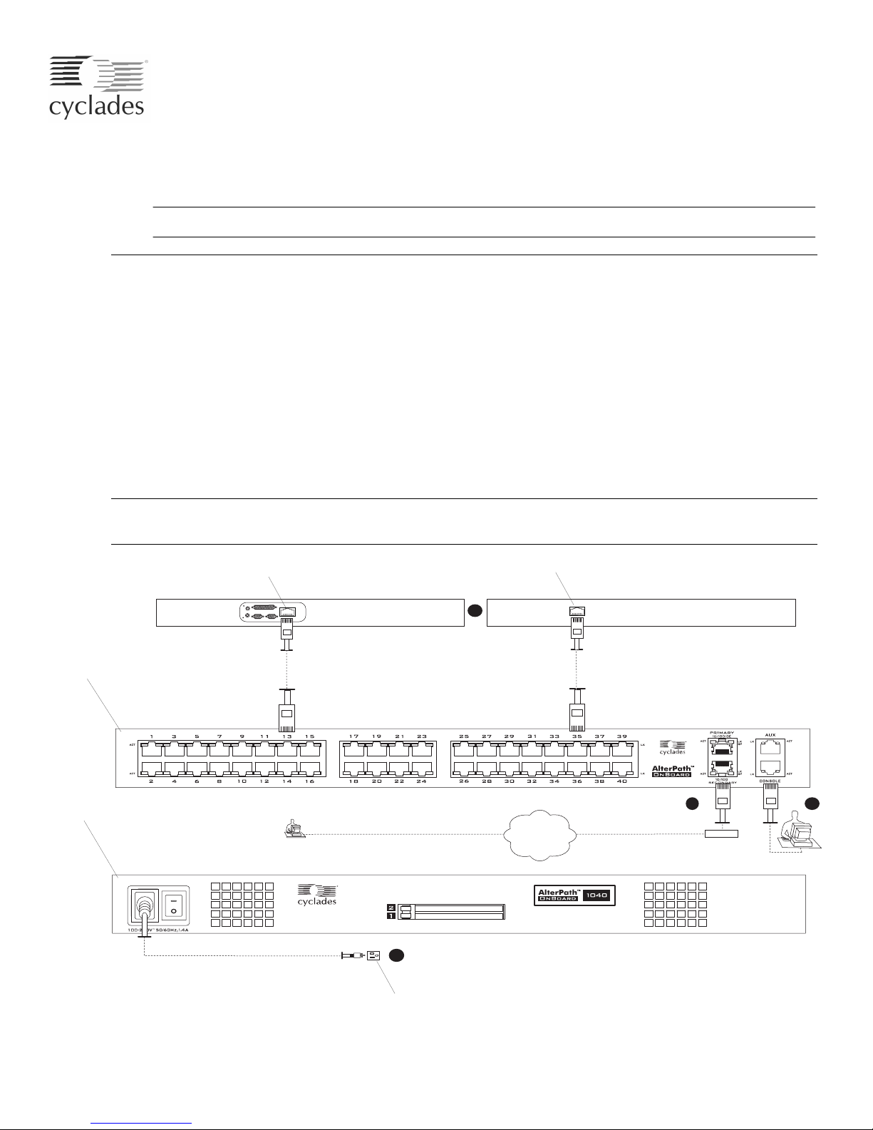
Note: Circled numbers in the following table correspond to circled numbers in the following figure.
Rackmount the OnBoard. Page 2
X
Connect the public network to the primary public Ethernet port. Page 2
Y
Connect service processors and other supported devices to the private Ethernet ports. Page 2
Z
Connect the OnBoard to a power source and turn power on. Page 2
[
Choose a method for enabling Web Manager access and proceed to either step
Connect a terminal to the console port to prepare for basic network configuration (if desired). Page 3
\
6. Enable access to the Web Manager by assigning a static IP address or configuring a DHCP
address.
7. Select a security profile, add users, and configure security and services using the Web Manager. Page 6
Note: Changing administrator passwords and selecting a security profile that suits your site’s security policies
are both mandatory for creating a secure configuration that reduces the risk of unwanted intrusions.
Service processor Ethernet port
OnBoard
back
\ or 6.
Ethernet port with console access on a server or other device
3
Page 2
Page 4
OnBoard
front
IP user
For more-detailed procedures, go to the page numbers listed in the table, and also see the AlterPath
OnBoard Installation Guide. For optional power management and modem connection instructions, see
“Advanced Procedures” on page 7.
4
Power source
Internet
2
Ethernet
Console user
5
Page 2

1. Rackmounting the AlterPath OnBoard
1. Rackmounting the AlterPath OnBoard
Two brackets are supplied with eight screws for attaching the brackets for rackmounting.
T To Rackmount the AlterPath OnBoard
1. Connect the brackets on each side at either the front or back edges. See the AlterPath OnBoard
Installation Guide for how to place the brackets and to review essential safety precautions, if needed.
2. Use appropriate mounting hardware to mount the OnBoard to the rack.
2. Making Public Ethernet Connections
On the back of the OnBoard, the two public Ethernet ports on the right are for connecting to one or two
public networks. For more about the options for configuring the public Ethernet ports, including setting up
failover, see the AlterPath OnBoard Installation Guide and the AlterPath OnBoard Administration Guide.
T To Make a Public Ethernet Connection
• Connect a standard Ethernet cable from a switch, router, or local area network (LAN) port to the
Ethernet port labeled “Primary.” Optionally, connect the “Secondary” port to the same or to another
network.
3. Connecting Devices
On the back of the OnBoard, 24 or 40 private Ethernet ports on the left are for connecting to the Ethernet
ports of service processors or of other devices. Connected devices should not be accessible on the public
network. See preparation steps in the installation guide.
T To Connect Devices to the Private Ethernet Ports
• Connect a standard Ethernet cable from a private Ethernet port on the OnBoard to any of the following
types of Ethernet ports on the other end:
• A dedicated Ethernet port on a service processor
• A dedicated Ethernet port on a router or other device that gives access to the device’s console
• A Ethernet port on a switch that is connected to multiple service processors (not recommended)
• A dedicated Ethernet port on a blade server managing multiple blades’ service processors
4. Connecting to a Power Source and Turning On the Power
Note: On OnBoards with two power supplies, connect each supply to a separate power source.
1. Make sure the OnBoard’s power switch(es) are off.
2. For models with AC power, plug the power cord(s) into the OnBoard and plug the other end(s) into
appropriate grounded AC power source(s).
3. For models with DC power, wire the terminal block(s) to separate DC power sources.
4. Turn on the power switch(es).
2 AlterPath OnBoard QuickStart Guide
Page 3

5. Connecting a Terminal to Configure Basic Network Settings
Methods for Enabling Web Manager Access
An administrator who knows the admin user’s password (cyclades) and who has network access to the
OnBoard needs to enter the OnBoard’s DNS name or IP address in a browser to bring up the Web Manager
and to finish the configuration of users and connected devices.
Perform one of the tasks in the following table to do the basic network configuration to enable the admin
user to log into the Web Manager.
Table 1-1: Methods for Enabling Web Manager Access
Method Considerations Where Described
Connect a terminal to the
console port and use the
cycli command to
assign a static IP address.
Use the DHCP-assigned
address.
Use the default OnBoard
IP address
192.168.160.10 to bring
up a Web Manager to set
a fixed IP address.
If using a static IP address, before you start, collect the following network information from the
administrator of the network.
• Hostname: _________________________________________________
• OnBoard’s public IP address: _________________________________
• Domain name: ______________________________________________
• DNS server’s IP address: _____________________________________
• Gateway IP address: _________________________________________
• Network Mask: _____________________________________________
You must be at the same location as the OnBoard
to make the local connection.
DHCP is enabled by default. “To Use a Dynamic IP Address to
You must temporarily change the network
portion of the IP address of a computer on the
same subnetwork as the OnBoard to be able to
use the default IP address in launching the Web
Manager.
• “Connecting a Terminal to Configure
Basic Network Settings” on page 3
• “Enabling Access to the Web
Manager” on page 4
Access the Web Manager” on page 6
“To Use the Default IP Address to
Access the Web Manager” on page 6
If you are using a network time server, also obtain the following information:
• NTP server IP address: _______________________________________
5. Connecting a Terminal to Configure Basic Network Settings
T To Connect to the Console Port
1. Connect the RJ-45 end of an RJ-45 to DB-9 6 ft. crossover cable to the console port and connect the
other end to a terminal or computer, using a USB adapter if needed.
3
Page 4

6. Enabling Access to the Web Manager
6. Enabling Access to the Web Manager
Perform one of the procedures in this section to enable remote configuration using the Web Manager.
T To Configure Basic Network Parameters Using a Terminal
Note: Alternatively, you can set the network interface eth0 parameters in Step 5 through 10 and the network
resolv parameters in Step 12 through 14 each in a single command line, for example:
cli> set network interface eth0 active yes method static address onboard_IP_address \
gateway gateway_IP_address netmask netmask broadcast broadcast_IP_address
1. Using either a terminal or a terminal emulation program installed on a computer that is connected to
the OnBoard’s console port, start a terminal session with the following factory default console port
settings.
Serial Speed: 9600 Data Length: 8 bits Parity: None Stop Bits: 1 Flow Control: None ANSI emulation
2. Log into the console port as root.
OnBoard login: root
Password: cyclades
The default password is “cyclades.”
Caution! For security, it is essential for root to change the password.
3. Enter the passwd command and enter and confirm a new password when prompted.
[root@OnBoard /root]# passwd
4. Enter the cycli command.
[root@OnBoard /root]# cycli
5. Make sure the primary Ethernet interface (eth0) is active.
cli> set network interface eth0 active yes
6. Specify static as the method (to set a static IP address).
cli> set network interface eth0 method static
7. Specify an IP address for the OnBoard.
cli> set network interface eth0 address onboard_IP_address
8. Specify a gateway IP address.
cli> set network interface eth0 gateway gateway_IP_address
4 AlterPath OnBoard QuickStart Guide
Page 5

6. Enabling Access to the Web Manager
9. Specify the netmask.
cli> set network interface eth0 netmask netmask
10. Specify the broadcast address for the OnBoard.
cli> set network interface eth0 broadcast broadcast_IP_address
11. Specify the hostname for the OnBoard.
cli> set network hostname OnBoard_name
12. Specify the domain name.
cli> set network resolv domain domain_name
13. Enter the IP address for the primary DNS (domain name) server.
cli> set network resolv dns0 DNS_server_IP_address
14. Optional: enter the IP address for a secondary DNS (domain name) server.
cli> set network resolv dns1 secondary_DNS_server_IP_address
15. Confirm the configuration for the interface.
cli> get network interface eth0
network interface active yes
network interface method static
network interface address 192.111.11.111
network interface netmask 255.255.255.0
network interface broadcast 192.111.11.255
network interface gateway none
network interface mtu 1500
16. Confirm the name server configuration.
cli> get network resolv
network resolv dns0 192.111.11.21
network resolv dns1 none
network resolv domain cyclades.com
17. Save the changes.
cli> commit
18. Exit from the cycli utility.
cli> quit
19. Log out and enter the IP address in a browser to bring up the Web Manager to finish configuration.
5
Page 6

7. Selecting a Security Profile, Adding Users and Configuring Devices Using the Web Manager
T To Use a Dynamic IP Address to Access the Web Manager
• Enter the IP address in a browser to bring up the Web Manager to finish configuration.
Caution! Make sure that the root user logs into the OnBoard console and changes the root password
from “cyclades.”
T To Use the Default IP Address to Access the Web Manager
1. On a computer that resides on the same subnet with the OnBoard, change the network portion of the IP
address of that computer to 192.168.160.
2. If you are using a network smaller than /24, change the subnet mask on your computer to match.
3. Bring up a browser on the computer whose address you changed, enter the OnBoard’s default IP
address (http://192.168.160.10) to bring up the Web Manager, and log in.
4. To allow subsequent use of the Web Manager from any computer, go to the Wizard: “Step 1: Network
Settings” to change the IP address to a fixed public IP address and to configure the other basic network
parameters.
5. Restore the computer’s IP address to its previous IP address.
6. If you changed the subnet mask, restore your computer’s subnet mask.
7. Enter the IP address in a browser to bring up the Web Manager to finish configuration.
Caution! Make sure that the root user logs into the OnBoard console and changes the root password
from “cyclades.”
7. Selecting a Security Profile, Adding Users and Configuring
Devices Using the Web Manager
For the tasks the administrator needs to perform to finish setting up security and configuring access to
connected devices, see the AlterPath OnBoard Administrator’s Guide. These tasks include selecting a
security profile, adding users, and configuring devices.
For More Information
For how OnBoard administrators and regular users access servers and devices that are connected to the
OnBoard, see “Accessing Connected Devices” in the AlterPath OnBoard User’s Guide. The user
documents are available at the following locations:
• On the documentation CD shipped with the product
•At http://www.cyclades.com/docs, under: “AlterPath OnBoard.”
6 AlterPath OnBoard QuickStart Guide
Page 7

Advanced Procedures
This section describes the following advanced procedures.
• Installing PCMCIA Cards in the Front Card Slots
• Connecting IPDUs or an External Modem to the AUX Port
Installing PCMCIA Cards in the Front Card Slots
The following order of installation is important:
• You can install and configure two PCMCIA cards in any order if they are of different types.
• If two PCMCIA cards are of the same type, you must insert and configure the first card in slot 1 before
inserting and configuring the second card in slot 2.
T To Install a PCMCIA Card
See the AlterPath OnBoard Installation Guide for a list of supported cards. Note: Some cards take up both
card slots.
1. Insert the PCMCIA card into the front slot(s) and slide the card in until it is firmly seated.
Advanced Procedures
PCMCIA card slots
PCMCIA card
2. If installing a modem card, use a phone cord to connect the card to a live telephone line.
3. Use the Web Manager → Settings → PCMCIA form to configure the PCMCIA card.
a. Click the Insert button on the form next to the number of the slot where the card is installed.
A prompt displays asking if you have inserted the card into the slot.
b. Click Yes.
c. Click the “Configure” button.
A PCMCIA card configuration form appears.
d. Select a card type from the “Card Type” pull-down menu.
Fill out the fields and select among the choices on the menus. See the AlterPath OnBoard
Administration Guide for configuration details for all PCMCIA card types.
7
Page 8

Advanced Procedures
T To Install Two PCMCIA Cards in the Front Card Slots
1. If both cards are of different types, install and configure both cards in any order.
See the AlterPath OnBoard Administrator’s Guide for details about configuring the PCMCIA cards.
2. If the cards are of the same type, insert and configure the first card in slot 1 before inserting and
configuring the second card in slot 2, as in the following steps:
a. Insert a card into slot 1.
b. Configure the card in slot 1. (See “To Install a PCMCIA Card” on page 7.)
c. Insert a card into slot 2.
d. Configure the card in slot 2.
Connecting IPDUs or an External Modem to the AUX Port
You can connect either of the following to the AUX port on the right back of the OnBoard:
• An external modem—You need a straight through RJ-45 to DB-9 CAT5 or greater cable alone or with
an adapter (DB-9 to DB-25 or USB) if needed for connecting the external modem.
• Any combination of AlterPath PM intelligent power distribution units (IPDUs) daisy-chained with up
to a total of 128 outlets—You need a straight through RJ-45 to RJ-45 CAT5 or greater cable for each
AlterPath PM IPDU.
Caution! Do not plug the OnBoard into a connected IPDU.
See the AlterPath OnBoard Administrator’s Guide for details about configuring the AUX port.
T To Connect a Modem to the AUX Port
1. Insert the RJ-45 end of the straight through RJ-45 to DB-9 cable into the AUX port on the OnBoard
and the appropriate connector or adapter (DB-9 to DB-25 or to USB) into the external modem.
2. Use a phone cord to connect the jack on the modem to a live telephone line.
3. Configure the AUX port for the modem.
T To Connect IPDU(s) to the AUX Port
1. Insert one end of the cable into an AUX port on the OnBoard and the other end into the “In” port of an
AlterPath PM.
2. To daisy-chain an additional IPDU, insert one end of another cable of the same type into the “Out”
port of an already-connected AlterPath PM, and insert the other end of the cable to the “In” port of the
next AlterPath PM.
3. Configure the AUX port for Power Management.
Cyclades Corporation
3541 Gateway Boulevard
Fremont, CA 94538 USA
1.888.CYCLADES (292.5233)
1.510.771.6100
1.510.771.6200 (fax)
http://www.cyclades.com
Part Number: PAC-0389
Release Date: February 2006
 Loading...