

Page 1
AlterPath™ OnBoard
User’s Guide
Software Version 1.1.0
Cyclades Corporation
3541 Gateway Boulevard
Fremont, CA 94538 USA
1.888.CYCLADES (292.5233)
1.510.771.6100
1.510.771.6200 (fax)
http://www.cyclades.com
Release Date: April 2006
Part Number: PAC0392
Page 2

© 2006 Cyclades Corporation, all rights reserved
Information in this document is subject to change without notice.
The following are registered or registration-pending trademarks of Cyclades
Corporation in the United States and other countries: Cyclades and AlterPath.
All trademarks, trade names, logos and service marks referenced herein, even when
not specifically marked as such, belong to their respective companies and are not to be
considered unprotected by law
Page 3

Contents
Before You Begin ...................................................xiii
Chapter 1: Introduction.............................................1
OnBoard Advantages for Server Management .................................... 3
Security Features Used in Access Control ........................................... 5
Types of Users ...................................................................................... 5
Types of User Authorizations .............................................................. 7
Authentication ...................................................................................... 8
Security Profiles’ Effects on Users’ Actions ....................................... 8
Types of Managed Devices ................................................................ 10
Options for Accessing the OnBoard, Managing User Passwords,
IPDU Power, and Devices .................................................................. 10
Command Line Access Through Console Logins ............................. 11
Accessing the OnBoard’s Console ..................................................... 12
User Shell (rmenush) .......................................................................... 13
OnBoard Shell (onbdshell) ................................................................. 14
Management Features Available to Authorized Users ....................... 14
What the Power Commands Do on Different Servers .................... 18
What the Reset Command Does on Different Servers ................... 18
Management Features Provided on Supported Device Types ........... 19
Using SSH with the OnBoard ............................................................ 20
Accessing the OnBoard Using SSH ............................................... 21
Device Management Commands for Use With SSH ..................... 21
Dial-in Access .................................................................................... 22
Cyclades Web Manager ..................................................................... 23
Power Management Options on the OnBoard ................................... 23
Accessing a Device’s Native Management Features ......................... 24
Native Web ..................................................................................... 24
Native Management Applications .................................................. 25
Page 4

Native IP Access Requirements ..................................................... 25
Tasks for Creating Secure Tunnels and Obtaining Native IP
Access ............................................................................................. 26
Information Users Need ..................................................................... 27
Sensor Plotting ................................................................................... 27
Common Tasks for Device Management ........................................... 31
Chapter 2: Web Manager Introduction...................35
Prerequisites for Using the Web Manager ......................................... 37
Requirements for Java Plug-In Availability ....................................... 38
Logging Into the Web Manager for Regular Users ............................ 42
Features of Regular Users’ Windows ................................................ 44
Web Manager Menu Options for Regular Users ................................ 45
Using the Devices Screen ................................................................... 45
Accessing a Service Processor’s Console .......................................... 47
Accessing a Device’s Console ........................................................... 48
Managing Power Through a Service Processor ................................. 49
Running Reset on a Service Processor ............................................... 51
Viewing Sensor Data .......................................................................... 51
Viewing and Clearing Event Logs ..................................................... 55
Accessing Native Features on a Service Processor ............................ 57
Accessing the OnBoard Console [Web Manager] ............................. 63
Managing Power Outlets on a Connected IPDU ................................ 65
Using the Outlets Manager Tab to Turn Power On and Off
and Check Power Status ................................................................. 66
Viewing IPDU Information ............................................................ 69
Using the “Software Upgrade” Screen to View the IPDU’s Current
Software Version ............................................................................ 71
Configuring Your Password ............................................................... 72
Chapter 3: Accessing the OnBoard and
Connected Devices..................................................73
Accessing the OnBoard’s Console ..................................................... 75
iv AlterPath OnBoard User’s Guide
Page 5

Accessing Device Management Features From the OnBoard’s
Console Menu .................................................................................... 77
Accessing the Console of a Device Through the OnBoard’s Console or
By Using SSH .................................................................................... 79
Creating an SSH Tunnel ..................................................................... 82
Creating a VPN Tunnel ...................................................................... 86
Routing Requirements for VPN Connections ................................ 88
IPSec VPN Routing Requirements ............................................. 88
PPTP VPN Routing Requirements ............................................. 88
Summary of VPN-related Requirements for Native IP Access ...... 90
VPN Through IPSec Connections .................................................. 91
PPTP VPN Connections ................................................................. 93
Obtaining and Using One Time Passwords for Dial-ins .................... 97
Appendix A: MindTerm Applet Reference.............99
Java Plug-In Requirements for Using MindTerm ............................ 100
Customizing MindTerm ................................................................... 100
Example MindTerm Window .......................................................... 100
MindTerm Terminal Menu Options ................................................. 101
Using Hot Keys During Console Sessions ....................................... 108
Glossary .................................................................109
Index .......................................................................135
Contents v
Page 6

vi AlterPath OnBoard User’s Guide
Page 7

Figures
Figure 1-1: Secure Path to a Connected Service Processor............. 3
Figure 1-2: Example Graph for Readings From a Fan Sensor....... 28
Figure 2-1: Web Manager Login Screen........................................ 42
Figure 2-2: User Options on the Web Manager............................. 44
Figure 2-3: Devices Web Manager Screen..................................... 46
Figure 2-4: Service Processor Console Example........................... 47
Figure 2-5: Device Console Example............................................ 49
Figure 2-6: Power Web Manager Screen....................................... 50
Figure 2-7: Example Power Status Dialog..................................... 50
Figure 2-8: Sensors Data Loading Message .................................. 52
Figure 2-9: Example of Unformatted Sensor Data ........................ 53
Figure 2-10: Graph Example............................................................ 54
Figure 2-11: Example Event Log Web Manager Screen ................. 56
Figure 2-12: Native IP: Not Available Status .................................. 57
Figure 2-13: Example HP iLO Native Web Interface...................... 60
Figure 2-14: OnBoard Console Login Screen.................................. 63
Figure 2-15: User Menu When Connected to the OnBoard’s
Console........................................................................ 64
Figure 2-16: IPDU Tabs................................................................... 66
Figure 2-17: IPDU Access Failed Message from “Outlets
Manager”..................................................................... 67
Figure 2-18: Access -> IPDU -> Outlets Manager Screen .............. 67
Figure 2-19: Outlets Manager Outlets State Close-up..................... 68
Figure 2-20: View IPDU Info Screen .............................................. 69
Figure 2-21: IPDU “Software Upgrade” Screen on the Web
vii
Manager....................................................................... 71
Page 8

Figure 2-22: “Password” Screen...................................................... 72
Figure 3-1: User Shell Menu.......................................................... 77
Figure 3-2: Device Access Menu................................................... 78
Figure 3-3: Service Processor Action Menu.................................. 79
Figure 3-4: OnBoard VPN Example Using IPSec......................... 86
Figure A-1: Root Log into MindTerm Running an SSH
Console Session ........................................................ 101
Figure A-2: Terminal Menu.......................................................... 102
viii AlterPath OnBoard User’s Guide
Page 9

Tables
Table P-1: Document Organization................................................ xiv
Table P-2: Related Documentation...............................................xvii
Table P-3: Typographic Conventions...........................................xviii
Table P-4: Other Terms and Conventions....................................xviii
Table 1-1: Access-related Security Features..................................... 5
Table 1-2: User Types, Responsibilities, and Default Password ...... 6
Table 1-3: Services and Other Functions Controlled by Security .....
Profiles............................................................................. 9
Table P-2: Console Login Types..................................................... 11
Table P-3: User Shell Default Menu Options ................................. 13
Table 1-1: Options and Command Names for Device
Management .................................................................. 15
Table P-2: Possible Power Management Command Effects........... 18
Table 1-1: Supported Device Types and Management Features..... 19
Table 1-2: Tasks for Creating Tunnels and Obtaining Native IP
Access............................................................................ 26
Table P-2: Sensor Graph Parameters .............................................. 28
Table P-3: Tasks for Managing Devices ......................................... 31
Table 2-1: Supported Browser and JRE Versions........................... 37
Table 2-2: Device Access Menu Options ....................................... 45
Table 2-3: Management Features Accessed Through the Web
Manager......................................................................... 46
Table 2-4: Information on the View IPDU Info Screen.................. 69
Table 3-1: Tasks for Enabling and Using Native IP Access Using
VPN............................................................................... 87
Table 3-2: Tasks for Enabling and Using Native IP Access Using
VPN............................................................................... 90
Table A-1: Console Session Terminal Menu Options ................... 102
Table A-2: Hot Keys Available During Console Sessions ............ 108
ix
Page 10

x AlterPath OnBoard User’s Guide
Page 11

Procedures
Chapter 2: Web Manager Introduction...................35
T
To Check Browsers for Java Plug-in Support............................................38
T
To Install JRE2 Software and Register the Java Plug-in...........................39
T
To Log Into the Web Manager...................................................................43
T
To Connect to a Service Processor’s Console [Web Manager].................48
T
To Connect to a Device’s Console [Web Manager]..................................49
T
To Manage a Server’s Power Through a Service Processor [Web
Manager]....................................................................................................50
T
To Reset a Server from a Service Processor [Web Manager] ...................51
T
To View a Server’s Sensor Data from a Service Processor [Web
Manager]...................................................................................................54
T
To View or Clear a Server’s Event Log Through a Service Processor
Web Manager] ...........................................................................................56
T
To Create a PPTP VPN Connection Profile on Windows—Example.......60
T
To Enable Access to Native Features on a Device [Web Manager]..........62
T
To Access the OnBoard’s Console [Web Manager]..................................64
T
To Manage Power Outlets on a Connected IPDU.....................................68
T
To View IPDUs Information .....................................................................71
T
To Change Your Password ........................................................................72
Chapter 3: Accessing the OnBoard and Connected
Devices .....................................................................73
T
To Access the OnBoard’s Console............................................................76
T
To Use a SSH Command to Connect Directly to a Device’s or Service
Processor’s Console...................................................................................80
T
To Use OnBoard’s Console Menus to Access the Device Management
Options.......................................................................................................81
T
To Exit from a Console Session.................................................... .... ..... ....82
xi
Page 12

T
To Use OpenSSH on Linux to Create an SSH Tunnel..............................83
T
To Use PuTTY on a Windows PC to Create an SSH Tunnel....................83
T
To Bring Up a Native Web Application When an SSH Tunnel Exists .....85
T
To Create an IPSec VPN Tunnel...............................................................92
T
To Enable Native IP Access Through an IPSec VPN Tunnel...................92
T
To Create a PPTP VPN Tunnel ...................................... ..... .... ..................93
T
To Enable Native IP Access Through a PPTP VPN Tunnel ..................... 94
T
To Access a Native Web Application When a VPN Tunnel Exists ..........94
T
To Access a Native Management Application...........................................95
T
To Generate an OTP Password When Challenged at Dial-in....................98
xii AlterPath OnBoard User’s Guide
Page 13

Before You Begin
This AlterPath OnBoard User’s Guide provides background information and
procedures for using the Cyclades™ AlterPath™ OnBoard to access servermanagement services that are provided by service processors and to gain
console access to devices that allow access to their consoles through Ethernet
ports.
Audience
This manual is intended for users who are authorized to connect to service
processors or to the consoles of connected servers or other types of devices
and to manage power through the OnBoard. The user’s guide is also
prerequisite reading for the administrator, who needs to understand what the
user can do on the OnBoard and how to conne ct to th e OnBoard before being
able to perform the procedures in the AlterPath OnBoard Administrator’s
Guide.
Note: This manual describes use of the OnBoard only. It does not describe
how to set up and administer other external services or servers that the
OnBoard may access for authentication, system logging, IPMI control, SNMP
notifications, data buffering, file sharing, or other purposes. This manual
assumes that users who are authorized to connect to service processors and
other devices through the OnBoard already know how to use the management
functions provided by the connected devices.
xiii
Page 14

Document Organization
The document contains the chapters listed in the following table.
Table P-1: Document Organization
Chapter Number and Title Description
1: Introduction
2: Web Manager Introduction
Provides an overview of the features of the
AlterPath OnBoard for the regular user,
along with necessary prerequisite
information for understanding the rest of the
information in this guide and in the
administrator’s guide.
Describes how authorized users use the W eb
Manager to do the following:
• Access management features of service
processors
• Access the console of other types of
devices that are connected to the private
Ethernet ports on the OnBoard
• Manage power
• Change their own passwords
xiv AlterPath OnBoard User’s Guide
Page 15

Table P-1: Document Organization (Continued)
Chapter Number and Title Description
3: Accessing the OnBoard and Con-
nected Devices
Describes options other than using the Web
Manager, which a user can use to do the
following:
• Access management features of service
processors
• Access the console of other types of
devices that are connected to the private
Ethernet ports on the OnBoard
• Manage power
• Change the user’s passwords
Options include the following:
• Connecting to the OnBoard console and
choose options from a menu
•Using ssh with device management com-
mands to access and manage devices
directly through the OnBoard.
A. “MindTerm Applet Reference
Describes using and customizing the
MindTerm applets that appear when the
console of the OnBoard or a connected
device is accessed through the Web
Manager. Also describes the special keys
and commands the user can use once
connected to the web interface or console of
a service processor or device.
Glossary
Defines terms needed for understanding
how to use Cyclades products.
Before You Begin xv
Page 16

Table P-1: Document Organization (Continued)
Chapter Number and Title Description
Index
Provides a way to look up information and
procedures. In the online version of this
manual, clicking the terms in the index
brings you to where they are used in the
manual.
xvi AlterPath OnBoard User’s Guide
Page 17

Related Documents
Before installing or using this product, refer to the release notes for important
information about supported hardware and software, known problems, and
outstanding bugs. You can download the release notes by going to http://
www.cyclades.com/support/downloads.php and searching for
the product name “AlterPath OnBoard.”
The following table lists the AlterPath OnBoard documents. As indicated, the
QuickStart Guide is printed, and it is also included with the other AlterPath
OnBoard documents in PDF format on the Documentation CD that is also
shipped with the product. The documents are also at http://
www.cyclades.com/support/downloads.php under “AlterPath OnBoard.”
Table P-2: Related Documentation
Printed and
Guide Title
AlterPath OnBoard QuickStart Guide YY
AlterPath OnBoard Installation Guide
AlterPath OnBoard Administrator’s Guide N (orderable) Y
Printed versions of this document and all the above listed documents can be
ordered from your Cyclades sales representative.
Documents for the AlterPath PM mentioned in this guide are also on the
Documentation CD shipped with the product, and they are also available at:
http://www.cyclades.com/downloads
Updated versions of this document will be posted on the downloads section of
the Cyclades website when Cyclades releases new versions of the software.
See “Additional Resources” on page xix for information about free software
upgrades.
Shipped?
N (orderable)
under the product’s name.
PDFs on
DocCD? Part Number
Y
PAC0389
PAC0390
PAC0391
Before You Begin xvii
Page 18

Typographic and Other Conventions
The following table describes the typographic conventions used in Cyclades
manuals.
Table P-3:Typographic Conventions
Typeface Meaning Example
Links
Emphasis Titles, emphasized or new words
Filename or
Command
Hypertext links or URLs Go to: http://www.cyclades.com.
See the AlterPath OnBoard
or terms
Names of commands, files, and
Quick Start.
Edit the pslave.conf file.
directories; onscreen computer
output.
User type What you type in an example,
# ifconfig eth0
compared to what the computer
displays
The following table describes other terms and conventions.
Table P-4:Other Terms and Conventions
Term or Convention Meaning Examples
Hot keys When hot keys are shown, a
plus (+) appears between
two keys that must be
pressed at the same time,
and a space appears
between two keys that must
be pressed sequentially.
• Ctrl+k p entered while the
user is connected to a KVM
port brings up an IPDU power
management screen. Ctrl and
k must be pressed at the same
time followed by p pressed by
itself.
• Ctrl+Shift+i entered
while the user is connected to a
serial port brings up the IPMI
power management utility. The
Ctrl key and the Shift and
i keys must be pressed at the
same time.
xviii AlterPath OnBoard User’s Guide
Page 19

Table P-4:Other Terms and Conventions (Continued)
Term or Convention Meaning Examples
Navigation shortcuts
\ in a command line
example
Shortcuts use the
symbol to indicate how to
navigate to Web Manager
or OSD screens.
Used in screen examples
when a command does not
fit in the space available.
Indicates that the whole
command should be
entered in either of the two
following ways:
• On one line without the
backslash
• On multiple lines with a
backslash at the end of
each line to tell the shell
that the command
continues on the
following line.
−>
Go to Configuration −> KVM −>
General
mode.
# openssl req -new \ nodes -key \
private_key.pem \
-out cert.csr
−> IP Users in Expert
Additional Resources
The following sections describe how to get technical support, training, and
software upgrades.
Cyclades Technical Support
Cyclades offers free technical support. To find out how to contact the su pport
center in your region, go to:
technical_support.php.
Before You Begin xix
http://www.cyclades.com/support/
Page 20

Cyclades Technical Training
To learn about the Cyclades Technical Training Center and the courses
offered, visit http:www.cyclades.com/training
an email to [email protected]
.
, call 1-888-292-5233, or send
Cyclades Software Upgrades
Cyclades offers periodic software upgrades for the AlterPath products free of
charge to current Cyclad e s cu stomers. You may want to check http://
www.cyclades.com/support/downloads.php from time to time to see if
upgrades are available for the OnBoard or for an AlterPath PM that you may
also be using with this product.
See the AlterPath OnBoard Administrator’s Guide for instructions on
upgrading the software on your AlterPath OnBoard and on an optionallyconnected AlterPath PM IPDUs.
xx AlterPath OnBoard User’s Guide
Page 21

Chapter 1
Introduction
The AlterPath OnBoard controls which users have access to connected
devices and creates a secure path between a remote user’s computer and a
connected device.
Note: This introduction describes what users need to know in order to
perform management actions on connected devices. The information in this
introduction is needed for understanding the information and procedures in
the rest of this guide and in the AlterPath OnBoard Administrator’s Guide.
The following table lists the topics in this chapter.
OnBoard Advantages for Server Management Page 3
Security Features Used in Access Control Page 5
Types of Users Page 5
Types of User Authorizations Page 7
Authentication Page 8
Security Profiles’ Effects on Users’ Actions Page 8
Types of Managed Devices Page 10
Options for Accessing the OnBoard, Managing User Passwords, IPDU
Power, and Devices
Command Line Access Through Console Logins Page 11
Accessing the OnBoard’s Console Page 12
User Shell (rmenush) Page 13
Page 10
OnBoard Shell (onbdshell) Page 14
Management Features Available to Authorized Users Page 14
1
Page 22

Management Features Provided on Supported Device Types Page 19
Using SSH with the OnBoard Page 20
Dial-in Access Page 22
Cyclades Web Manager Page 23
Power Management Options on the OnBoard Page 23
Accessing a Device’s Native Management Features Page 24
Information Users Need Page 27
Sensor Plotting Page 27
Common Tasks for Device Management Page 31
2 AlterPath OnBoard User’s Guide
Page 23
OnBoard Advantages for Server Management
OnBoard Advantages for Server Management
The OnBoard provides access to server-management services that are
provided by service processors. Service processors are out-of-band
management controllers that many vendors include in their servers. The
OnBoard provides a single source for authentication, authorization, and
management for multiple types of service processors. Using the OnBoard,
users can access and manage multiple servers from a single point without
having to learn how to use multiple service processor-management interfaces.
For example, the ability to manage power is provided by most service
processors, but each service processor has its own interface and its own
commands for power management. The OnBoard al lows an authorized user to
manage power on multiple servers from multiple vendors using a single
interface and a single set of commands.
The security features provided by the OnBoard work together to create a
secure path between a user and a server that is being managed.
Key
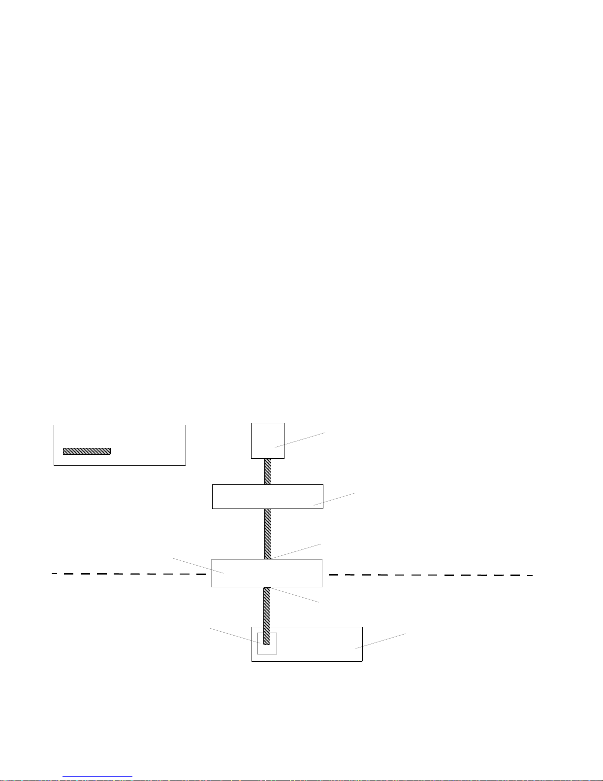
Figure 1-1 is a conceptual illustration of a secure path between a remote user
and a service processor through the OnBoard. (Users can also be on the same
LAN as the OnBoard and the connected devices.)
Secure path
OnBoard
Service Processor’s
Dedicated Ethernet Port
Remote user workstation
Router/optional firewall
Public network Ethernet port
Private network Ethernet port
Server
Figure 1-1: Secure Path to a Connected Service Processor
Introduction 3
Page 24

OnBoard Advantages for Server Management
In Figure 1-1, the public network is above the dashed line, and the private
network is below the dashed line. The dedicated Ethernet port of a service
processor is connected to one of the OnBoard’s private Ethernet ports. The IP
address of the public Ethernet port is the only publicly-defined IP address.
To allow management of the connected device, each device has a privatelydesignated IP address and at the administrator’s discretion, each device may
also have a virtual IP address. If virtual addresses are defined, users may be
allowed to see a connected device’s virtual IP address but not to see the
device’s privately-defined IP address.
In the example, the remote user accesses the OnBoard through a network
connection to the public Ethernet port and then selects a service processor
management action that user is authorized to perform on a specific service
processor . (Users may also dial into the OnBoard through an optional external
modem or PCMCIA modem card.)
After the user selects the desired management action, the OnBoard then
creates a secure connection between the user and the service processor, acting
as a proxy on behalf of the user when communicating with the service
processor. While the user is performing any of the service processor
management actions for which the user is authorized, the connection between
the OnBoard and the service processor is kept separate and protected from the
connection between the user and the OnBoard. Nothing that happens on the
private network is exposed to the public network. Depending on the mode of
access, HTTPS or SSH can be used to protect communications that are
transported on the public network between the user and the OnBoard.
4 AlterPath OnBoard User’s Guide
Page 25

Security Features Used in Access Control
Security Features Used in Access Control
The OnBoard allows administrators to enforce an organization’s security
policies by providing security features that control who can access
management features on connected devices. The access-related security
features are shown in the following table with links to where the features are
described in more detail.
Table 1-1: Access-related Security Features
Security Features Where Described
User types and authorizations “Types of Users” on page 5
“Types of User Authorizations” on page 7
The security profile in effect on the
OnBoard and which services are turned on
or off
Separate authentications for accessing the
OnBoard and connected devices
Types of Users
The OnBoard supports two main types of users:
• Users authorized to administer the OnBoard and to administer connected
devices, called administrative users
• Users authorized to perform one or more management functions on one or
more connected devices, called au tho rized users
Two predefined administrators are root and admin, and they cannot be
deleted.
The admin user can do the following:
“Security Profiles’ Effects on Users’ Actions”
on page 8
“Authentication” on page 8
• Access the Web Manager and use any of its functions
• Access the OnBoard’s console and use the unrestricted shell
• Invoke the OnBoard configuration utility, cycli
• Invoke any Linux commands available to the non-root user
• Invoke any Linux commands available to the root user by using the sudo
command
Introduction 5
Page 26

Types of Users
The root user can do the following:
• Access the OnBoard’s console and use the unrestricted shell.
• Invoke the OnBoard configuration utility, cycli
• Invoke any Linux commands available to the root user
The root user cannot access the Web Manager.
Either root or admin can add regular user accounts and authorize them to
access management features on connected devices. Optionally, addin g regular
users to the “admin” group makes them administrative users able to perform
OnBoard administration.
The following table summarizes the responsibilities of each type of user and
provides the default password for each type of user.
Table 1-2: User Types, Responsibilities, and Default Password
User Name Responsibilities Default Password
root Cannot be deleted. Only direct logins to the
OnBoard command line are allowed. Runs
the cycli utility to do initial network
configuration, as described in the AlterPath
OnBoard Installation Guide. Also can run
other OnBoard-specific commands and
Linux commands on the command l ine of the
Linux shell.
admin Cannot be deleted. Has full access to every
function of the Web Manager. Also can run
the cycli utility on the command line of the
Linux shell and can use any Linux
commands available to the non-root user.
cyclades
cyclades
6 AlterPath OnBoard User’s Guide
Page 27

Types of User Authorizations
Table 1-2: User Types, Responsibilities, and Default Password (Continued)
User Name Responsibilities Default Password
administratorassigned
User account optionally configured by an
administrator to be able to perform
management functions on devices conn ected
to the OnBoard. Users’ access to devices and
to device-management features is controlled
by authorizations. Users with permission to
access management features on connected
devices are referred to as “authorized users.”
Note: If a regular user is assigned to the
“admin” group, that user can also perform
the same administrative functions on the Web
Manager as the “admin” user, as described
above. Regular users added to the admin
group are referred to as administrative users.
Types of User Authorizations
Users can be authorized for the following:
administratorassigned
• Access to connected service processors or other types of connected
devices
• Access to management features available on the devices tha t users are
authorized to access:
• Service Processor Console
• Device Console
• Sensors
•Power
• Event Log
• Native IP
For details, see “Management Features Av ailable to Authorized Users” on
page 14.
Introduction 7
Page 28

Authentication
Note: The administrator may create and enable a custom security profile that
has the “override authorization” feature set, which causes all authenticated
users to have all access to all connected devices. For details, see “Security
Profiles’ Effects on Users’ Actions” on page 8.
Authentication
Anyone accessing the OnBoard must log in by entering a username and
password. Controlling access by requiring users to enter names and passwords
is called authentication. The usernames and passwords entered during login
attempts are checked against a database. Access is denied if the username or
password is not valid.
The password database being checked can reside either locally (on the
OnBoard) or on an authentication server on the network.
The OnBoard user is required to enter a username and password in the
following cases:
• When logging into the OnBoard
The authentication method chosen for the OnBoard is used for all access
through telnet, ssh, or the Web Manager. By default, logins to the
OnBoard use Local authentication.
• When accessing a service processor or other connected device.
Users may be required to enter different username and password pairs when
accessing the OnBoard than when accessing a connected device.
Security Profiles’ Effects on Users’ Actions
The administrator selects a security profile for the OnBoard based on the
security requirements of the organization. The security profile may limit
which services are available to users and which functions may be allowed or
disallowed.
Note: All of the features and procedures described in this guide work when
the Moderate security profile is in effect.
8 AlterPath OnBoard User’s Guide
Page 29

Security Profiles’ Effects on Users’ Actions
Each OnBoard has a security profile, which controls the following:
• Which services are turned on
• Whether authorizations are being checked
Services and other functions controlled by security profiles are listed in the
following table:
Table 1-3: Services and Other Functions Controlled by Security Profiles
Service Other Functions That Can Be Allowed/Disallowed
FTP
HTTP, HTTPS Redirect HTTP automatically to HTTPS
ICMP
IPSec
PPTP
RPC
SNMP v1, v2c, v3
SSH v1, SSH v2 Allow root login using SSH
Assign an alternate port to SSH
Telnet Allow Telnet to OnBoard
Override authorization—enable access based on authentication only
Specify a default authentication type to apply by default to all subsequently-configured
devices.
Services can also be turned on and off independently from the security profile.
For more details, see “Understanding Services” in the AlterPath OnBoard
Administrator’ s Gu ide .
Note: If you are prevented from using a service you need to use, such as FTP
or SNMP, talk with the OnBoard’s administrator to find out if the service can
be enabled or if another way of performing a necessary task is available that is
consistent with your site’s security policies.
Introduction 9
Page 30

Types of Managed Devices
Types of Managed Devices
The connected device can be one of the following types:
•A service processor.
• A server or other type of device that does not have a service processor but
that provides access to its command line through a dedicated Ethernet port
This type of device includes servers that redirect their serial console
output to dedicated Ethernet ports (which provide a type of access
generally referred to as serial over LAN or SoL).
• A device with a dedicated Ethernet port that supports management access
via Telnet, SSH, SNMP, or the OnBoard's native IP access capability
Note: The term “device” is used in this guide when referring to a service
processor, server , or other connected device, unless the type of device must be
clearly stated in the context.
Options for Accessing the OnBoard, Managing
User Passwords, IPDU Power, and Devices
Authorized users can access the OnBoard through the local network, the
Internet, and through dial-ins to an optional modem or phone card for the
following purposes:
• Performing device mana gement actions on connected devices
• Managing outlets on optionally-connected AlterPath PM IPDUs
• Managing the user’s own password.
For details about modem access, see “Management Features Provided on
Supported Device Types” on page 19.
The following means are available for logging into the OnBoard and
performing the above-listed actions:
• Using the Web Manager and choosing from a list of menu options.
For more details, see “Cyclades Web Manager” on page 23.
10 Alter Path OnBoard User’s Guide
Page 31

Command Line Access Through Console Logins
• Using an SSH application or the ssh command on the command line of
the user’s workstation to connect to the OnBoard’s command line, and
then choosing from a list of menu options.
See “Accessing the OnBoard’s Console” on page 12, “User Shell
(rmenush)” on page 13, and “OnBoard Shell (onbdshell)” on page 14.
Users can also use ssh on the command line to execute a service processor
management command directly on the service processor. For details, see
“Using SSH with the OnBoard” on page 20. The device management features
are described under “Management Features Available to Authorized Users”
on page 14.
The OnBoard provides device management commands for ssh that are not
provided for telnet. Because ssh is encrypted, and therefore more secure,
by default ssh is the only supported means of performing device
management actions directly on a device, as summarized in the following list:
• Users cannot use telnet to connect directly to a device and perform
management actions through the OnBoard.
• Users can use ssh to connect directly to a device and perform
management actions through the OnBoard.
Command Line Access Through Console Logins
Administrators and authorized users can access the command line of the
OnBoard and of service processors, servers, and other connected devices by
accessing the device’s console. Users of any type can log into a console of any
of the above listed types using either the Web Manager, menus available
through the OnBoard console, or ssh. The following table provides links to
where console access is defined.
Table P-2:Console Login Types
Console Type Where Documented
OnBoard • “Accessing the OnBoard’s Console” on page 12
•
“To Access the OnBoard’ s Console” on page 76
Device or service
processor console
Introduction 11
• “To Use OnBoard’s Console Menus to Access the Device
Management Options” on page 81
“To Use a SSH Command to Connect Directly to a Device’s or Service
•
Processor’s Console” on page 80
”
Page 32

Accessing the OnBoard’s Console
When a user connects to any console using the Web Manager, a window
running a MindTerm applet appears with an encrypted SSH connection
between the user’s computer and the console. Mi ndTerm is an SSH client that
includes an integrated xterm/vt100 terminal emulator and that runs as a Java
applet within a browser window.
To use MindTerm, the user’s browser must have a Java plug-in enabled, as
described in “Requirements for Java Plug-In Availability” on page 38.
See Appendix A, “MindTerm Applet Reference” for details about using and
configuring the applets and about hot keys that can be used during console
sessions through the Web Manager.
Accessing the OnBoard’s Console
Administrators and authorized users can access the OnBoard’s console, in the
following three ways.
• By local logins through the console port
Local OnBoard administrators or authorized users can access the
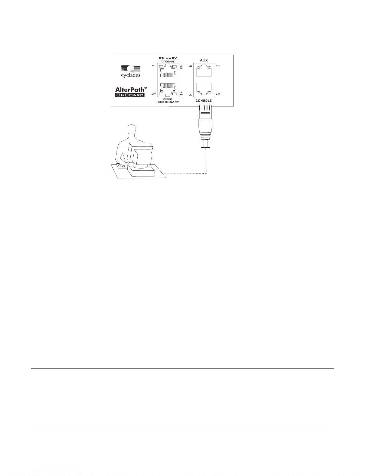
command line by logging in through the console port. This requires the
user or administrator to have physical access to a terminal or computer
that is connected to the OnBoard’ s console port as shown in the following
figure. The user or administrator logs in through a terminal or through a
terminal emulation program on the connected computer.
12 Alter Path OnBoard User’s Guide
Page 33
User Shell (rmenush)
• By using SSH
Remote administrators and authorized users can access the OnBoard’s
command line through a SSH connection between the user ’s computer
and the OnBoard. See “Using SSH with the OnBoard” on page 20.
• By clicking “Connect to OnBoard” on the Web Manager.
After logging into the Web Manager, any type of user can access the
console by clicking “OnBoard” in the left menu and then clicking the
“Connect to OnBoard” button.
User Shell (rmenush)
The default login shell for OnBoard non-administrative users is /usr/bin/
rmenush. After logging in as described in “Accessing the OnBoard’s
Console” on page 75, users see the menu options des cribed in the following
table.
Table P-3:User Shell Default Menu Options
Menu Option Function
Access Devices Executes the onbdshell to display a list of devices the user can
access. See “OnBoard Shell (onbdshell)” on page 14.
Change Password Allows the user to set a new password.
Logout Logs the user out of the OnBoard’s console
Introduction 13
Page 34

OnBoard Shell (onbdshell)
The OnBoard administrator may modify the menu options and commands
shown in Table 3 on page 1 3 so that users may be presented with a different
menu of choices.
A user moves from one item to another on the menu and submenus by using
the keyboard’s arrow keys. A line (-) appears next to the selected item.
After an option is selected, pressing the “Enter” or “Return” key brings up a
submenu or runs the selected command. The following section describes the
submenu that appears when “Access Devices” is selected.
OnBoard Shell (onbdshell)
The OnBoard shell, /usr/bin/onbdshell, displays a list of devices an
authorized user can access. A submenu lists the device management actions
available to the user. See “Accessing Device Management Features From the
OnBoard’s Console Menu” on page 77 for more details.
Management Features Available to Authorized
Users
The following table describes the management features for the different types
of managed devices. These features are available a user through the Web
Manager, through the onbdshell menu, and through the ssh utility on the
command line. The first column shows the following:
• The option name for the feature in the Web Manager
• The option name for the feature in the onbdshell action menu
• The command name used with ssh on the command line to access the
feature.
14 Alter Path OnBoard User’s Guide
Page 35

Management Features Available to Authorized Users
The “Device” column shows the type of device that supports each feature
(“dev” for device without a service processor and “SP” for a service
processor).
Table 1-1: Options and Command Names for Device Management (Sheet 1 of 3)
Web Manager Option /
onbdshell Option /
ssh Command Device Description
Service Processor Console /
Access the service
processor’s
console / spconsole
Device Console /
Access the device’s
console / devconsole
Power /
Manage power / power
SP Gives access to the service processor’s console
(sometimes called the native command interface or
NCI).
dev/SP Gives access to the console of one of the following:
• A server that allows console access through its
service processor
• A device without a service processor that presents
a command line interface through its Ethernet
port
SP In the Web Manager, brings up a screen with the
power management options. When access to the
service processor goes through the OnBoard’s
console, brings up a list of power management
options. When the user performs power
management directly on the service processor using
the ssh command, power management options are
performed using power management command s.
Some types of service processors offer multiple
options for powering off and power cycling a
server . For details, see “What the Power Commands
Do on Different Servers” on page 18.
Introduction 15
The following rows show the Web Manager and
OnBoard shell menu options and the name of the
power management commands that can be executed
directly on the service processor using the ssh
command from the user’s computer.
Page 36

Management Features Available to Authorized Users
Table 1-1: Options and Command Names for Device Management (Sheet 2 of 3)
Web Manager Option /
onbdshell Option /
ssh Command Device Description
Web Manager /
onbdshell Option ssh Command
Reset /
reset
Sensors /
sensors
Turn power on / Turn
poweron
power on
Turn power of f / Turn
poweroff
power off
Power cycle / Turn
powercycle
power off then
on
Check power status /
powerstatus
Get power status
SP Resets the server where the service processor
resides. Various type of resets are available on
service processors. See “What the Reset Command
Does on Different Servers” on page 18.
SP Displays unformatted sensor data collected from
the server by its service processor. The page
provides a button that displays graphs of data from
individual sensors.
16 Alter Path OnBoard User’s Guide
Page 37

Management Features Available to Authorized Users
Table 1-1: Options and Command Names for Device Management (Sheet 3 of 3)
Web Manager Option /
onbdshell Option /
ssh Command Device Description
Event Log /
Manage the event
log /
sel
Native IP /
Enable native IP /
nativeipon
Disable native IP /
nativeipoff
SP Displays the system event log (SEL) menu from the
server where the service processor resides. Events
are messages logged when system management
events are detected. The events can be logged by
the service processor or by the server. The user can
view or clear event logs directly on the service
processor using the ssh command.
Web Manager /
ssh Command.
onbdshell Option.
View event log sel
Clear event log clearsel
SP Used when a service processor supports access to a
native web application or provides a management
application that runs on the user’s computer. For
“Native IP” to be available, a VPN connection must
be active between the remote computer and the
OnBoard. When the option to enable native IP is
chosen, the user can then do one of the following:
Introduction 17
• Launch a browser on the remote computer to
bring up the native web application
• Launch the management application on the
remote computer
Note: Instead of using a VPN tunnel, a user may
use a ssh tunnel to access a device’s native web
application without going through the Web
Manager or the OnBoard’s console. For more
details, see “Accessing a Device’s Native
Management Features” on page 24.
Page 38

Management Features Available to Authorized Users
Note: When a connected device does not have a service processor., “Device
Console” and “Native IP” are the only management features available by
default. The OnBoard command templates and device management Expect
scripts can be customized to make other management features available.
What the Power Commands Do on Different
Servers
The effects of the service processor power management commands differ
from one vendor’s service processor to another. The possible options are
described in the following table. If a service processor provides more than one
of the options shown, the hard option is performed.
Table P-2:Possible Power Management Command Effects
Power Command Option
Power off • Hard power off: remove the power
• Soft power off: shut down the operating system before removing
the power
Power cycle (turn
power off, then on
again, to reboot the
server)
• Hard power cycle: remove the power, wait several seconds, and
then turn the power on again (to reboot the server)
• Soft power cycle: shut down the operating system, wait several
seconds, and then turn power on again
What the Reset Command Does on Different
Servers
The effects of the “Reset” command differ from one vendor’s service
processor to another, and sometimes the types of resets available on service
processors of the same type from the same vendor differ from one firmware
version to another. In addition, sometimes service processors have more than
one type of reset, as described in the following list:
• W arm reset (or warm boot): only the server’s operating system is restarted
• Cold boot: the server is fully restarted (the same effect as issuing a
“Power cycle” command)
18 Alter Path OnBoard User’s Guide
Page 39

Management Features Provided on Supported Device Types
If n service processor has more than one type of reset option, the OnBoard
“Reset” command performs the highest level of reset: the cold boot option if
available.
If the OnBoard administrator is configuring a service processor that provides
multiple reset options, the administrator can customize an associated service
processor management script to cause the “Reset” command to perform one
of the lower levels of reset that are available on the service processor.
Customizing service processor management scripts in described in the
AlterPath OnBoard Administrator’s Guide.
Management Features Provided on Supported
Device Types
The following table shows the management features available on the
supported service processors and on devices without service processors that
present a command line interface through a dedicated Ethernet port.
Table 1-1: Supported Device Types and Management Features
Supported
Service
Processors/
Devices
RSA II
IPMI 1.5
DRAC
ILO
Device
SP
Console
YYYYYY
YNYYYY
YYYYNY
YYYYNY
NYNNNY
Device
Console Power
Event
Log Sensors Native IP
Introduction 19
Page 40

Using SSH with the OnBoard
Using SSH with the OnBoard
Both SSH v1 and SSH v2 services are supported on the OnBoard. The
OnBoard administrator may disable either version; if only one version is
enabled, authorized users can use only a client running the same version that
is enabled.
If SSH is enabled, authorized users can use ssh in the following ways.
• Access the OnBoard console using ssh and then connect through the
OnBoard to perform device management actions.
See “Accessing the OnBoard Using SSH” on page 21.
•Using ssh with special device management commands to perform device
management actions without having to log into the OnBoard first.
See “Device Management Commands for Use With SSH” on page 21.
The format of the ssh command line is shown in the following screen
example.
ssh -t username:devicename@onboard_IP_or_DNS_name [command]
where:
-t is required to launch an interactive session.
username is the name of the authorized user.
devicename is the name/alias that was assigned to the device by the
OnBoard administrator.
onboard_IP_or_DNS_name is the IP address of the OnBoard or its DNS
name.
command is one of the OnBoard-specific device management
commands.
• Create an SSH tunnel to get access to a native web application on a
device.
See “Accessing a Device’s Native Management Features” on page 24 and
“Information Users Need” on page 27.
20 Alter Path OnBoard User’s Guide
Page 41

Using SSH with the OnBoard
Accessing the OnBoard Using SSH
As described under “User Shell (rmenush)” on page 13 and “OnBoard Shell
(onbdshell)” on page 14, authorized users who connect to the OnBoard’s
console are presented with a menu of choices. From the initial menu, users
can bring up a list of devices that they are authorized to access and then access
a submenu of management actions they can perform on the selected device.
Users can use ssh to connect to OnBoard’s console and to access the
rmenush menu in the following ways:
• ssh username:@onboard_IP_or_DNS_name
• ssh -t username:@onboard_IP_or_DNS_name rmenush
Both of the above commands give the non-administrative user access to the
same menu. If an administrative user enters the first command line without the
rmenush command, the user gets a shell prompt.
Users can use ssh to access the submenu of device management actions for a
specific device in the following ways:
• ssh username:device_alias@onboard_IP_or_DNS_name
• ssh -t username:device_alias@onboard_IP_or_DNS_name rmenush
Both of the above commands give the user access to the same menu.
Device Management Commands for Use With SSH
Users can perform device management actions directly on a service processor
by using the ssh command along with one of the following OnBoard-specific
device management commands:
• spconsole
• devconsole
• poweron, poweroff, powercycle, powerstatus
• reset
• sensors
• sel, clearsel
• native_ip_on, native_ip_off
The -t option is required to launch an interactive session.
For details about the management actions performed by the commands, see
“Management Features Available to Authorized Users” on page 14.
Introduction 21
Page 42

Dial-in Access
The format of the ssh command line is shown in the following screen
example.
ssh -t username:devicename@onboard_IP_or_DNS_name command
where:
username is the name of the authorized user.
devicename is the name/alias that was assigned to the device by the OnBoard
administrator.
onboard_IP_or_DNS_name is the IP address of the OnBoard or its DNS
name.
command is one of the OnBoard-specific device management ssh
commands.
For example, for authorized user fred to turn on the power for a server
whose name is configured on the OnBoard as drac, when the IP address of
the OnBoard is 192.168.29.22, the poweron command would be
entered as shown in the following screen example:
ssh -t fred:[email protected] poweron
Dial-in Access
Authorized users can dial into the OnBoard through either of the following
types of optional modems and phone cards:
• An external modem connected to the AUX port
• A modem, GSM, or CDMA PCMCIA card inserted into one of the front
PCMCIA slots
The OnBoard can be accessed using PPP when the following prerequisites are
completed:
• The modem or phone card has been configured on the OnBoard for PPP
or Autodetect and for optional callback
22 Alter Path OnBoard User’s Guide
Page 43

Cyclades Web Manager
• The PPP application at the remote caller’s end has been configured for
dialing into the OnBoard and optionally for callback from the OnBoard.
• The user account has been configured for PPP access, and the user knows
the PPP username and password configured by the OnBoard
administrator.
The OnBoard can be accessed from a terminal emulation program on the
user’s computer if the modem or phone card is configured for Login or
autodetect. The one-time password authentication method can be configured
for login access to PCMCIA modem or phone cards.
Cyclades Web Manager
Both authorized users and administrative users can access the Web Manager
from a supported browser using HTTP or HTTPS. Authorized users can use
the Web Manager to log into devices, manage power on devices plugged into
optional AlterPath PM IPDU power units, and change their own passwords.
Only administrative users have access to the OnBoard screens for configuring
users or ports.
See Chapter 2, “Web Manager Introduction” for information about using the
Web Manager that is needed by authorized users and administrative users.
Browser access to the Web Manager is through one of the following ways:
• Through the Ethernet
• Through one of the modem types described in “Management Features
Provided on Supported Device Types” on page 19.
Power Management Options on the OnBoard
Authorized users and OnBoard administrators can turn power off, turn power
on, and turn power off and on again quickly (cycle power) to reboot devices.
The OnBoard provides the following two types of power management options
for administrators and authorized users:
• IPDU power management
Allows the user to manage power for any type of AC device that may be
plugged into an AlterPath PM intelligent power distribution unit (IPDU),
when the IPDU is connected to the OnBoard’s AUX port.
Introduction 23
Page 44

Accessing a Device’s Native Management Features
For details about the Web Manager −> IPDU screen that is used to
manage power outlets and for links to procedures, see “Managing Power
Outlets on a Connected IPDU” on page 65.
• Service processor power management
Allows the user to manage power for a server whose service processor is
connected to the OnBoard when the service processor provides power
management capabilities. See “Management Features Available to
Authorized Users” on page 14 for details about power management of
connected servers with service processors.
For links to sections that describe how to access a service processor’s
power management capabilities using the Web Manager or ssh, see
Table 3 on page 31.
Accessing a Device’s Native Management
Features
Native Web
Native IP access gives an authorized user authenticated access to a device’s
native features such as integrated web servers and other proprietary interfaces
that are available over IP.
Access to native functions on some service processors is through a proprietary
web interface on the service processor. HP iLO, Dell DRAC, and IBM RSA II
service processors have a local web server running and provide a web
interface that allows administrators remote access for provisioning,
monitoring, and managing the server. The web interface is accessed through a
specific port number.
The monitoring and management features supported by some service
processors through their native web interfaces include access to the server’s
serial or graphical user interface, power control, access to sensor data and
server event logs, SNMP agents, and virtual media.
24 Alter Path OnBoard User’s Guide
Page 45

Accessing a Device’s Native Management Features
Native Management Applications
Native applications are proprietary service processor management
applications provided by some server vendors, such as HP InSight Manager,
IBM Director, and Dell Open Manage. Access to a native application usually
requires the user to have the application installed on the user’s computer.
Some management applications reside on the service processor itself.
After an authenticated and authorized user establishes a VPN connection and
chooses the “Native IP” option, the user can bring up the management
application from where it resides on the user's computer or from the service
processor’s console.
Native IP Access Requirements
Native IP access depends on the following being true:
• The service processor must provide the desired native management
functionality.
For example, service processors using IPMI protocols do not provide
native web access.
• The user can be trusted to use the native IP access appropriately.
• The OnBoard administrator has authorized the user to access the “Native
IP” option on a service processor
• The user has created a secure tunnel to the OnBoard:
• An SSH tunnel gives access to native web applications only
• A VPN tunnel gives access to both native web and native management
applications
Introduction 25
Page 46

Accessing a Device’s Native Management Features
T asks for Creating Secure Tunnels and Obtaining
Native IP Access
The following table lists the tasks for creating secure tunnels and obtaining
native IP access and where the tasks are documented.
Table 1-2: Tasks for Creating Tunnels and Obtaining Native IP Access
Task Where Documented
Create an SSH tunnel, and
bring up a browser to access a
native web application
Create a VPN tunnel using
either IPSec or PPTP, and do
one of the following:
• Bring up a browser to access
a native web application
• Launch a native
management application
from the device or from a
remote workstation.
• “Creating an SSH Tunnel” on page 82
• “To Use OpenSSH on Linux to Create an SSH Tunnel”
on page 83
• “To Use PuTTY on a Windows PC to Create an SSH
Tunnel” on page 83
• “To Bring Up a Native Web Application When an SSH
Tunnel Exists” on page 85
• “Creating a VPN Tunnel” on page 86
• “Routing Requirements for VPN Connections” on page
88
• “Summary of VPN-related Requirements for Native IP
Access” on page 90
• “VPN Through IPSec Connections” on page 91
• “To Create an IPSec VPN Tunnel” on page 92
• “To Enable Native IP Access Through an IPSec VPN
Tunnel” on page 92
• “PPTP VPN Connections” on page 93
• “To Create a PPTP VPN Tunnel” on page 93
• “To Enable Native IP Access Through a PPTP VPN
Tunnel” on page 94
• “To Access a Native Web Application When a VPN
Tunnel Exists” on page 94
• “To Access a Native Management Application” on page
95
26 Alter Path OnBoard User’s Guide
Page 47

Information Users Need
Information Users Need
Users need to obtain the following information from the OnBoard
administrator.
• The user’s name and password
• The names of devices that the user is authorized to manage and the device
management actions that the user is authorized to perform
• Information about services that are enabled or disabled on the OnBoard.
For example, the administrator may have configured the OnBoard so that
HTTP or SSH v1 are disabled.
• A list of IPDU power outlets the user may be authorized to manage.
• For native IP users using PPTP VPN connections, the PPTP password,
which may be different from the password used to access the OnBoard.
• For native IP users using IPSec VPN connections, authentication
information for either shared secret or RSA key authentication.
Sensor Plotting
An authorized user or administrative user can view graphical displays of
sensor data collected from servers by their se rvice processors and can also
modify graph display settings, either through the Web Manager, the user shell
menu, by using ssh with the sensor commands.
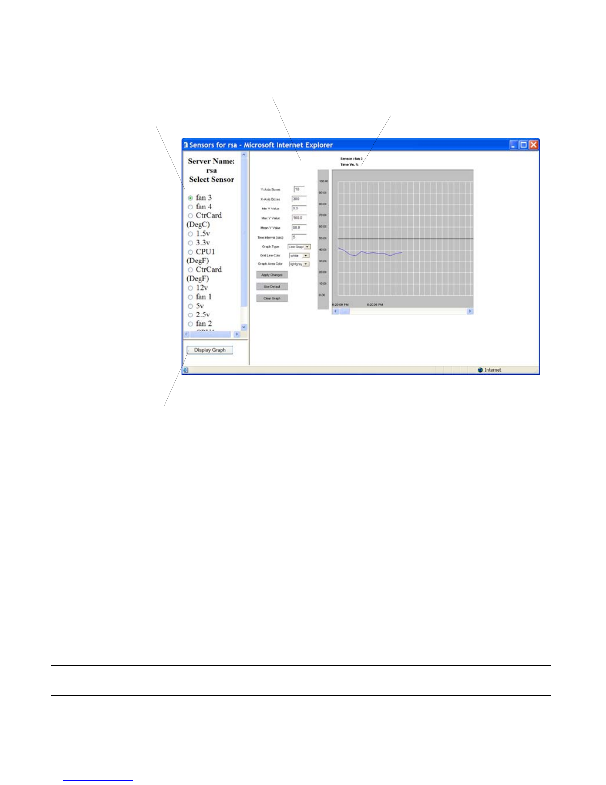
The following figure shows an example graph.
Introduction 27
Page 48
Sensor Plotting
Graph area
Graph heading
Sensors list
“Display Graph” button
Figure 1-2: Example Graph for Readings From a Fan Sensor
The graph heading reads: “Time Vs. sensor_value.” sensor_value varies with
the type of data being measured. The example fan sensor reading in Figure 12 has a heading “Time Vs. %” because the value being sensed is the
percentage of total possible fan speed. Examples of other possible values for
sensor_value (which vary from one vendor’s service processor to the next)
are “Volts,” “Degrees Centigrade,” and “Degrees Farenheit.”
The following table shows graph features that can be modified. An error
message appears if you enter a value that is greater than or lower than the
supported range of values.
Table P-2:Sensor Graph Parameters
Field/Menu Use Default
y-Axis Boxes
Specify a different number of rows. 10 1-55
Allowed
Values
28 Alter Path OnBoard User’s Guide
Page 49

Sensor Plotting
Table P-2:Sensor Graph Parameters (Continued)
Allowed
Field/Menu Use Default
Values
x-Axis Boxes
Min Y Value
Max Y Value
Mean Y Value
Specify a different number of columns.
Each graph cell represents the interval
between readings.
Specify a different minimum sensor value
to be plotted on the x axis. The only valid
keys are numeric keys, period (.), and
hyphen (-).
Specify a different maximum sensor value
to be plotted on the y axis. The only valid
keys are numeric keys, period (.), and
hyphen (-).
Specify a different mean value to use as a
basis for comparison with the actual
detected value. The only valid keys are
numeric keys, period (.), and hyphen (-).
In line graphs, the Mean Temp is
indicated by a black horizontal line. In bar
graphs, the colors of the bars indicate the
following:
300 1-999
Varies with
the type of
sensor
Varies with
the type of
sensor
Varies with
the type of
sensor
Varies with
the type of
sensor
Varies with
the type of
sensor
Varies with
the type of
sensor
• Blue – Less than the mean Y value.
• Red – Greater than mean Y value.
• Black – Equal to the mean Y value.
Time Interval
Specify a different frequency in seconds
for fetching sensor data. The only valid
keys are numeric keys.##
Graph Type
Introduction 29
Chose another graph type. • Line
55-300
•Line
Graph
Graph
•Bar
Graph
Page 50

Sensor Plotting
Table P-2:Sensor Graph Parameters (Continued)
Allowed
Field/Menu Use Default
Values
Grid Line Color
Graph BG Color
Choose another color for the lines. • white • yellow
green
cyan
gray
darkgray
lightgray
magenta
orange
pink
white
Select the background color. • light gray • yellow
green
cyan
gray
darkgray
lightgray
magenta
orange
pink
white
For procedures for monitoring sensors, see “To View a Server’s Sensor Data
from a Service Processor [Web Ma nager]” on page 54.
30 Alter Path OnBoard User’s Guide
Page 51

Common Tasks for Device Management
Common Tasks for Device Management
The following table shows the tasks related to accessing and managing
devices and lists the options the OnBoard user and administrator have for
performing those tasks.
Table P-3:Tasks for Managing Devices
Task Options and Where Described
Connect to a device’s console • Using the Web Manager
See “Accessing a Device’s Console” on page 48.
• Using an SSH utility or
to connect to the OnBoard’s console before
accessing the device’s console through a menu.
See “To Access the OnBoard’s Console” on page
76.
• Using ssh on the command line to connect directly
from the user’s computer to the device’s console.
See “T o Use a SSH Command to Connect Directly
to a Device’s or Service Processor’s Console” on
page 80.
ssh on the command line
Connect to a service processor’s console • Using the Web Manager
See “Accessing a Service Processor’s Console” on
page 47
• Using an SSH utility or
to connect to the OnBoard’s console before
accessing the service processor’s console through
a menu. See “To Access the OnBoard’s Console”
on page 76
•Using
directly from the user’s computer to the service
processor’s console with OnBoard-specific
spconsole command. See “To Use a SSH
Command to Connect Directly to a Device’s or
Service Processor’s Console” on page 80.
ssh on the command line to connect
ssh on the command line
Introduction 31
Page 52

Common Tasks for Device Management
Table P-3:Tasks for Managing Devices (Continued)
Task Options and Where Described
Manage a server’s power through its
service processor
Manage a system’s event logs through its
service processor
• Using the Web Manager
See “To Manage a Server’s Power Through a
Service Processor [Web Manager]” on page
50
• Using ssh to connect to the OnBoard and then
manage power
See “Accessing the OnBoard Using SSH” on
page 21.
• Using ssh on the command line with power
commands
See “Device Management Commands for Use
With SSH” on page 21.
• Using the Web Manager
See “To View or Clear a Server’s Event Log
Through a Service Processor [Web
Manager]” on page 56
• Using ssh to connect to the OnBoard and
then view or clear event logs.
See “Accessing the OnBoard Using SSH” on
page 21.
Using ssh on the command line with event
log commands.
See “Device Management Commands for Use
With SSH” on page 21.
32 Alter Path OnBoard User’s Guide
Page 53

Common Tasks for Device Management
Table P-3:Tasks for Managing Devices (Continued)
Task Options and Where Described
View server sensor data through the
server’s service processor
• Using the Web Manager
See “To View a Server’s Sensor Data from a
Service Processor [Web Ma nager]” on page
54
• Using ssh to connect to the OnBoard and then
view or clear event logs.
See “Accessing the OnBoard Using SSH” on
page 21.
• Using ssh on the command line with event
log commands.
See “Device Management Commands for Use
With SSH” on page 21.
Introduction 33
Page 54

Common Tasks for Device Management
34 Alter Path OnBoard User’s Guide
Page 55

Chapter 2
Web Manager Introduction
This chapter describes how authorized users and administrative users use the
W eb Manager to access the OnBoard, to manage connected service processors
and other devices, to manage power outlets on any connected AlterPath PM
IPDUs, and to manage their own passwords.
This chapter provides background information listed in the following table.
Prerequisites for Using the Web Manager Page 35
Requirements for Java Plug-In Availability Page 38
Logging Into the Web Manager for Regular Users Page 42
Features of Regular Users’ Windows Page 44
Web Manager Menu Options for Regular Users Page 45
Using the Devices Screen Page 45
Accessing a Service Processor ’s Console Page 47
Accessing a Device’s Console Page 48
Managing Power Through a Service Processor Page 49
Running Reset on a Service Processor Page 51
Viewing Sensor Data Page 51
Viewing and Clearing Event Logs Page 55
Accessing Native Features on a Service Processor Page 57
Accessing the OnBoard Console [Web Manager] Page 63
Managing Power Outlets on a Connected IPDU Page 65
Configuring Your Password Page 72
35
Page 56

The procedures in this chapter are listed in the following table.
To Log Into the Web Manager Page 43
To Connect to a Service Processor’s Console [Web Manager] Page 48
To Connect to a Device’s Console [Web Manager] Page 49
To Manage a Server’s Power Through a Service Processor [Web Manager] Page 50
To Reset a Server from a Service Processor [Web Manager] Page 51
To View a Server’s Sensor Data from a Service Processor [Web Manager] Page 54
To View or Clear a Server’s Event Log Through a Service Processor [Web
Page 56
Manager]
To Create a PPTP VPN Connection Profile on Windows—Example Page 60
To Enable Access to Native Features on a Device [Web Manager] Page 62
To Access the OnBoard’s Console [Web Manager] Page 64
To Manage Power Outlets on a Connected IPDU Page 68
To View IPDUs Information Page 71
To Change Your Password Page 72
36 Alter Path OnBoard User’s Guide
Page 57

Prerequisites for Using the Web Manager
Prerequisites for Using the Web Manager
This section describes the required browsers, preparation, and browser plugins needed for different types of access.The prerequisites described in this
section must be complete before anyone can access the Web Manager. If you
have questions about any of the following prerequisites, contact your site’s
system or network administrator.
• The IP address of the OnBoard must be known.
Entering the IP address of the OnBoard in the address field of one of the
supported browsers listed in Table 2-1 on page 37 is the first step required
to access the Web Manager.
When DHCP is enabled, a device’s IP address may or may not be fixed,.
When the address is not fixed, anyone wanting to access the OnBoard
must find out the currently-assigned IP address each time. If DHCP is
enabled and you do not know how to find out the current IP address of the
OnBoard, contact your system administrator for help.
• A user account must be defined on the Web Manager.
By default, the “admin” has an account on the Web Mana ger. An
administrator can add regular user accounts to access connected devices
using the Web Manager.
For accessing the Web Manager, you can use any type of modern computer
that has access to the network where the AlterPath OnBoard is installed and
any modern browser (such as Internet Explorer 5.5 or above, Netscape 6.0 or
above, Mozilla, or Firefox) with a Java 2 plug-in.
The browser and JRE versions in the following tables have been tested and
proven to work.
Table 2-1: Supported Browser and JRE Versions
Browser Version JRE Version
Firefox
Internet Explorer
1.0.7 JRE 1.5.0_01
6.0 JRE 1.5.0_02
Mozilla 1.7 JRE 1.5.0_01
Netscape 7.1 JRE 1.5.0_02
Web Manager for Authorized Users 37
Page 58

Requirements for Java Plug-In Availability
Requirements for Java Plug-In Availability
The Web Manager launches Java applets in the following situations:
• When establishing console access to the OnBoard and to SPs and other
connected devices
• When displaying sensor data.
The Java applets rely on the Java plug-in being installed on the computer and
registered with the browser being used.
Installing Java 2 Runtime Environment (J2RE) software, Standard Edition,
automatically installs the needed Java plug-in. After you download and install
the JRE software, you then must make sure the Java plug-in is registered with
the browser. The following table provides links to the related procedures.
To Check Browsers for Java Plug-in Support Page 38
To Install JRE2 Software and Register the Java Plug-in Page 39
Note: The Java Runtime Environment is also called Java 2 Platform,
Standard Edition (J2SE) at the java.sun.com
is called Java 2.
website, and in the IE browser, it
T To Check Browsers for Java Plug-in Support
1. To check Internet Explorer on Windows, do the following steps.
a. Go to Tools
b. Scroll down to find the Java section.
A line with an adjacent checkbox should appear with the wording
“Use JRE 1.5.0_NN” as shown in the following figure.
−> Internet Options −> Advanced.
i. If the line appears and the checkbox is not checked, check the
checkbox to register the plug-in with the browser.
38 Alter Path OnBoard User’s Guide
Page 59

Requirements for Java Plug-In Availability
ii. If the line does not appear, install the JRE 2 software as described
under “To Install JRE2 Software and Register the Java Plug-in”
on page 39.
2. To check Netscape or Mozilla on Windows, do the following steps.
a. Go to Edit
b. Check the “Enable Java” checkbox.
c. To see what version of the Java plug-in is registered, do the following
steps.
i. Go to Help
ii. Scroll to the Java Plug-in section.
iii. Check whether the registered Java plug-in is the same as the
version you installed.
3. If needed, go to “To Install JRE2 Software and Register the Java Plug-in”
on page 39.
−> Preferences −> Advanced.
−> About Plug-ins.
T To Install JRE2 Software and Register the
Java Plug-in
1. Make sure the Java 2 Runtime Environment (JRE 2) software, version
1.4.2 or 1.5 is installed on the computer.
2. If needed, download the JRE 2 software from:
http://java.sun.com/j2se/1.4.2/download.html
OR
http://java.sun.com/j2se/1.5.0/download.jsp
3. If needed, follow the instructions at:
http://java.sun.com/j2se/1.4.2/jre/install.html
OR
http://java.sun.com/j2se/1.5.0/install.html
4. Register the plug-in.
Installing JRE2 1.5 gives you an option to register the Java plug-in for the
browsers on your computer during installation. Follow the prompts to
Web Manager for Authorized Users 39
Page 60
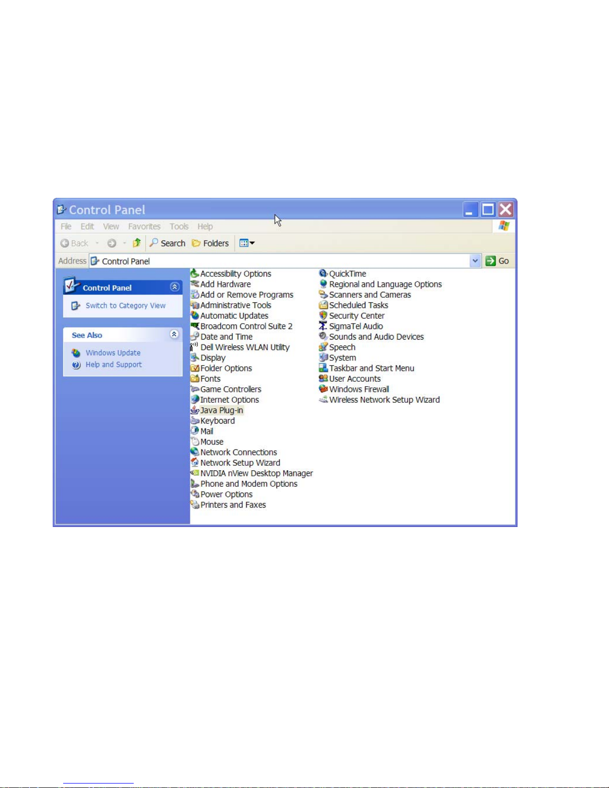
Requirements for Java Plug-In Availability
register the plug-in. If you install JRE2 1.4.2, you need to manually
register the Java plug-in afterwards, as described in Step 5
5. To enable the Java plug-in, do the following steps.
a. Go to the Control Panel on the start menu on the Windows computer.
The Control Panel appears.
b. If the Java Plug-in icon appears, click it.
The Java Plug-in Control Panel appears.
c. Click the Browser tab.
The Browser form appears.
40 Alter Path OnBoard User’s Guide
Page 61
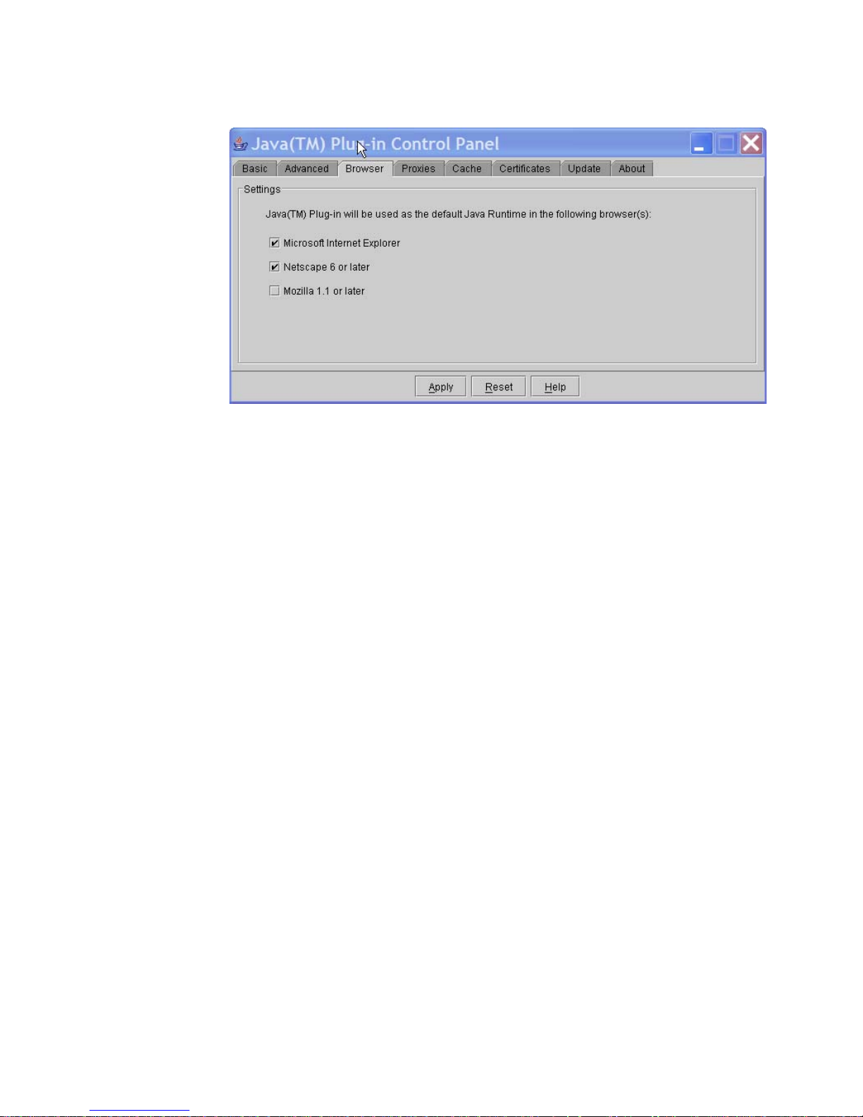
Requirements for Java Plug-In Availability
d. Check a checkbox next to the name of each browser in which to
enable the Java plug-in.
e. Click “Apply.”
6. Verify that the browser is successfully registered with the browser by
performing this procedure: “To Check Browsers for Java Plug-in
Support” on page 38.
Web Manager for Authorized Users 41
Page 62
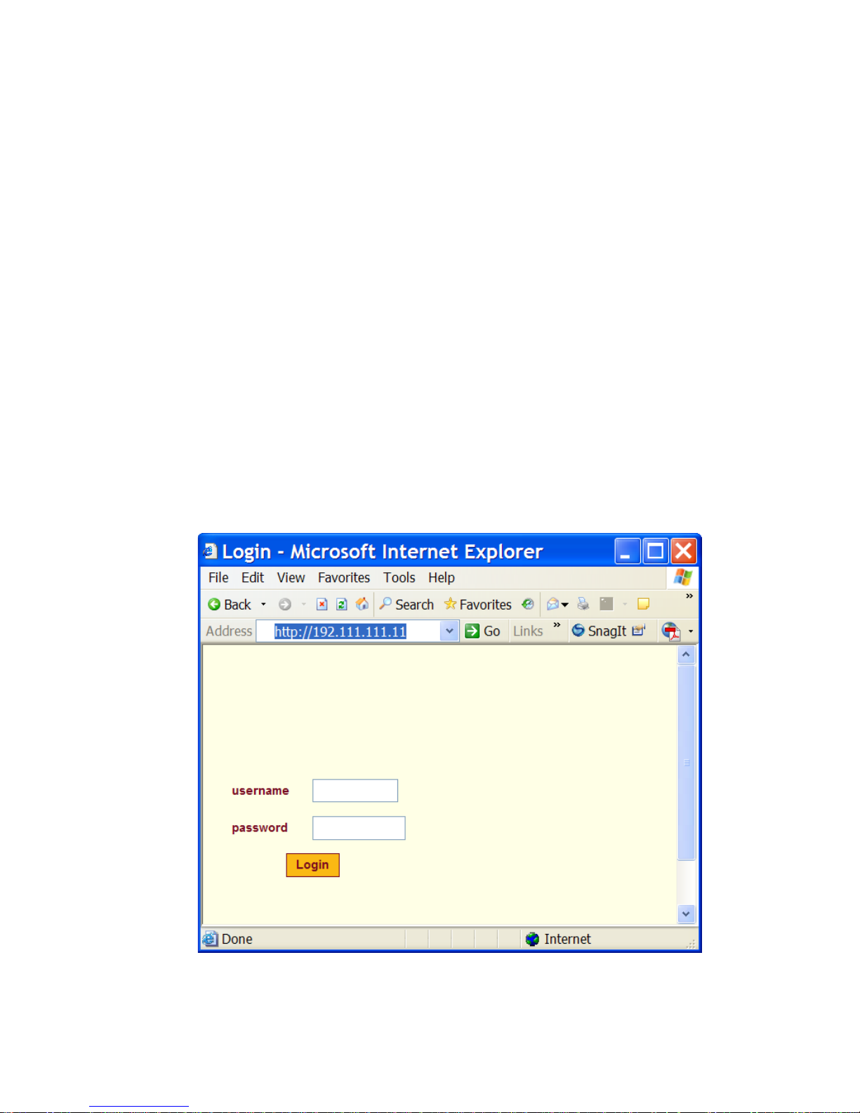
Logging Into the Web Manager for Regular Users
Logging Into the Web Manager for Regular
Users
Both authorized users and OnBoard administrators can access the Web
Manager from a browser using HTTP or HTTPS over the Internet or through a
dial-in or callback PPP connection.
After being authenticated during login, authorized users can use the Web
Manager to log into devices, manage power, and change their own passwords,
but they cannot use the Web Manager for configuring users or devices. Any
number of regular users can connect to the Web Manager at the same time.
OnBoard administrators can perform additional user and device configuration
tasks through the Web Manager. See the AlterPath OnBoard Administrator’s
Guide for details.
The following figure shows the login screen for the W eb Manager that appears
when the OnBoard’s IP address is entered in a Microsoft Internet Explorer
browser.
Figure 2-1: Web Manager Login Screen
42 Alter Path OnBoard User’s Guide
Page 63

Logging Into the Web Manager for Regular Users
Any number of regular users can connect to the Web Manager at the same
time.
See “Cyclades Web Manager” on page 23 for more about how to use the Web
Manager and “Prerequisites for Using the Web Manager” on pa ge 37 for the
required browsers, preparation, and browser plug-ins needed for different
types of access.
T To Log Into the Web Manager
This procedure assumes you have a valid username and password for an
account authorized to perform device management and that your computer
has one of the following types of access to the OnBoard:
• A network connection
• A PPP connection
1. Enter the IP address of the OnBoard in a supported browser.
See Table 2-1 on page 37 for a list of supporte d browsers, if needed.
The Web Mana ger login screen appears.
2. Enter your username and password.
3. Click the “Login” button.
Web Manager for Authorized Users 43
Page 64
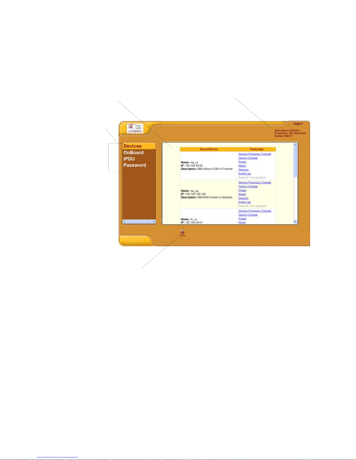
Features of Regular Users’ Windows
Features of Regular Users’ Windows
The following figure shows features of the Web Manager that appear when
regular users log in.
Screen area
Left menu
Logout button and OnBoard information
Help button
Figure 2-2: User Options on the Web Manager
A menu of options appears on the left. When you select an option, the fields,
buttons, and menus that appear in the screen in the middle change according
to which option is selected.
44 Alter Path OnBoard User’s Guide
Page 65

Web Manager Menu Options for Regular Users
Web Manager Menu Options for Regular Users
The user can select from the options shown in Figure 2-2 to do the tasks
shown in the following table, which gives links to where the tasks are
described.
Table 2-2: Device Access Menu Options
Task Where Described
Connect to a device “Using the Devices Screen” on page 45
Connect to the OnBoard “Accessing the OnBoard Console [Web Manager]” on pa ge
63
Manage outlets on an IPDU “Managing Power Outlets on a Connected IPDU” on page 65
Change your password “Configuring Your Password” on page 72
OnBoard administrators see the same list of options shown in Table 2-2 under
the administrator’s “Access” tab. The “Access” tab is one of multiple tabs that
are available on the Web Manager whenever an administrator logs in.
Administrators can refer to the AlterPath OnBoard Administrator’s Guide for
more details.
Using the Devices Screen
The Devices screen lists device groups and individual devices that are not in
groups for every device the user is authorized to access. Clicking the plus (+)
sign next to the name of a group expands the list of device entries. Clicking a
minus (-) sign hides the list of device entries.
The entry for each device has the following:
• Links to the management features the user is allowed to access on that
device
• The name (alias) assigned to the device
• A real IP address (if a virtual IP address is not assigned to the device)
• A virtual IP address (if one is assigned to the device)
• A description of the device
Web Manager for Authorized Users 45
Page 66
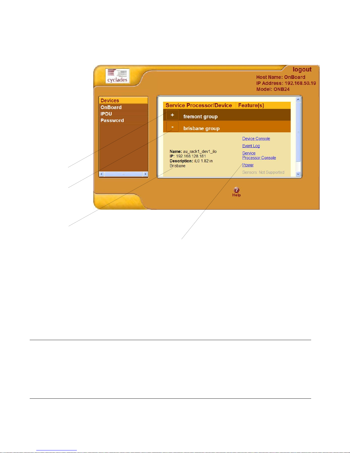
Using the Devices Screen
The Devices screen is shown in the following figure.
Unexpanded
device group
Expanded
device group
Device entry
Links to management features supported by the device
Figure 2-3: Devices Web Manager Screen
Links to device management features are active only when they are supported
for a particular device. The following table lists the management features,
which are introduced in T able 1-1, “Options and Command Names for Device
Management,” on page 15. The following table provides links to more
information about accessing these features using the Web Manager.
Table 2-3: Management Features Accessed Through the Web Manager
Feature Where Described
Service Processor Console
“Accessing a Service Processor’s Console” on page 47
Device Console “Accessing a Device’s Console” on page 48
Power “Viewing and Clearing Event Logs” on page 55
Reset “Running Reset on a Service Processor” on page 51
46 Alter Path OnBoard User’s Guide
Page 67
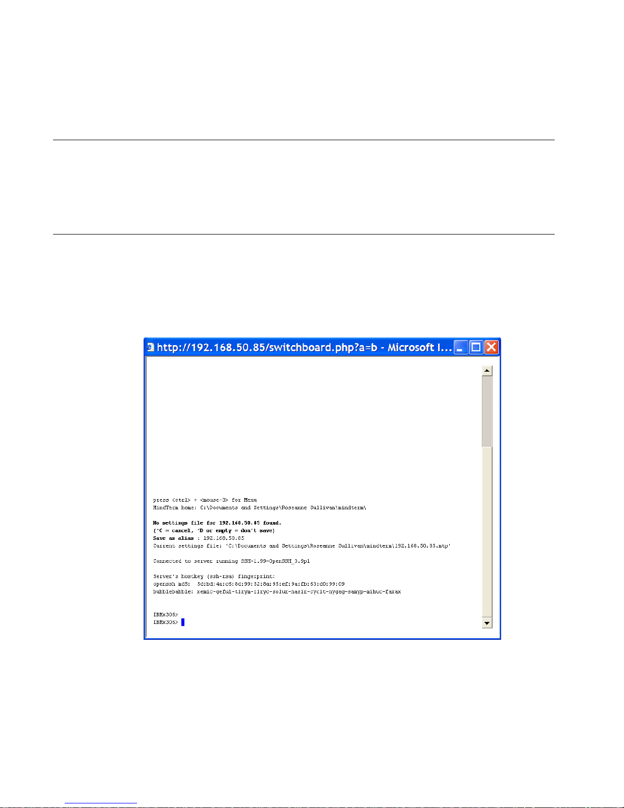
Accessing a Service Processor’s Console
Table 2-3: Management Features Accessed Through the Web Manager (Continued)
Feature Where Described
Sensors “Viewing Sensor Data” on page 51
Event Log “Viewing and Clearing Event Logs” on page 55
Native IP “Accessing Native Features on a Service Processor” on
page 57
Accessing a Service Processor’s Console
Clicking the “Service Processor Console” link on the Devices screen gives
you access to the command line of the service processor. A window running a
MindTerm Java applet appears, as shown in the following screen example.
Figure 2-4: Service Processor Console Example
Web Manager for Authorized Users 47
Page 68

Accessing a Device’s Console
T To Connect to a Service Processor’s
Console [Web Manager]
1. Bring up the Web Manager and log in.
See “To Log Into the Web Manager” on page 43, if needed.
2. From the list of devices that displays on the “Devices” screen, click the
“Service Processor Console” link that is associated with the server whose
console you want to access.
A MindTerm window displays with an ssh connection to the device.
3. If authentication is enabled for the service processor, log in as prompted.
Accessing a Device’s Console
Clicking the “Device Console” button on the Devices screen launches a
terminal window running a Java applet and creates a console connection with
the device. The following figure shows an example terminal window with a
connection to a device console on a Compaq Proliant server with an iLO type
service processor.
48 Alter Path OnBoard User’s Guide
Page 69
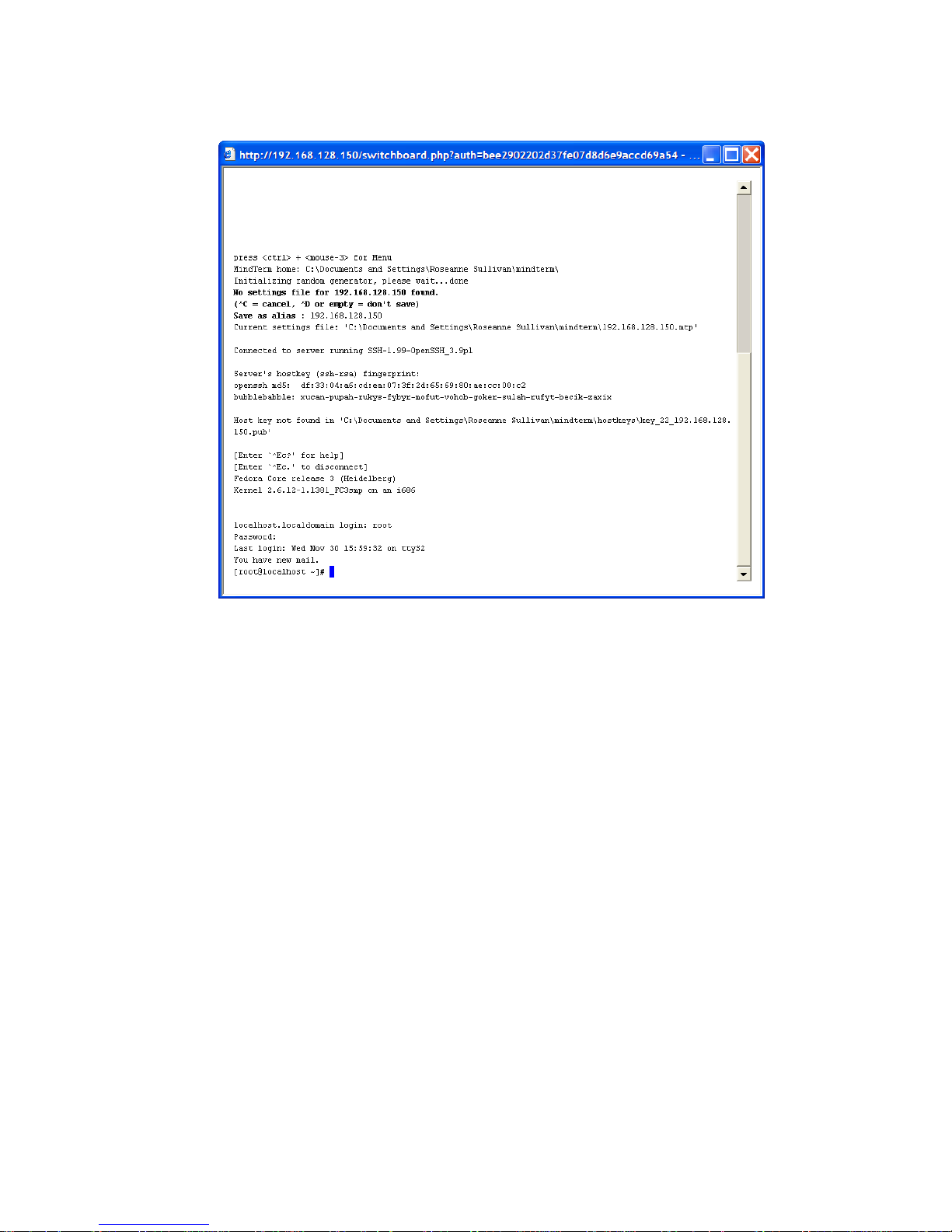
Managing Power Through a Service Processor
Figure 2-5: Device Console Example
T To Connect to a Device’s Console [Web
Manager]
1. Bring up the Web Manager and log in.
See “To Log Into the Web Manager” on page 43.
2. From the list of devices that displays on the “Devices” screen, click the
“Device Console” link for the server or device whose console you want to
access.
A MindTerm window displays with an ssh connection to the device.
3. If authentication is enabled for the device, lo gin as prompted.
Managing Power Through a Service Processor
Clicking the “Power” button on the Devices screen gives you access to a
menu of power management options that are available on the service
processor, as shown in the following screen example.
Web Manager for Authorized Users 49
Page 70
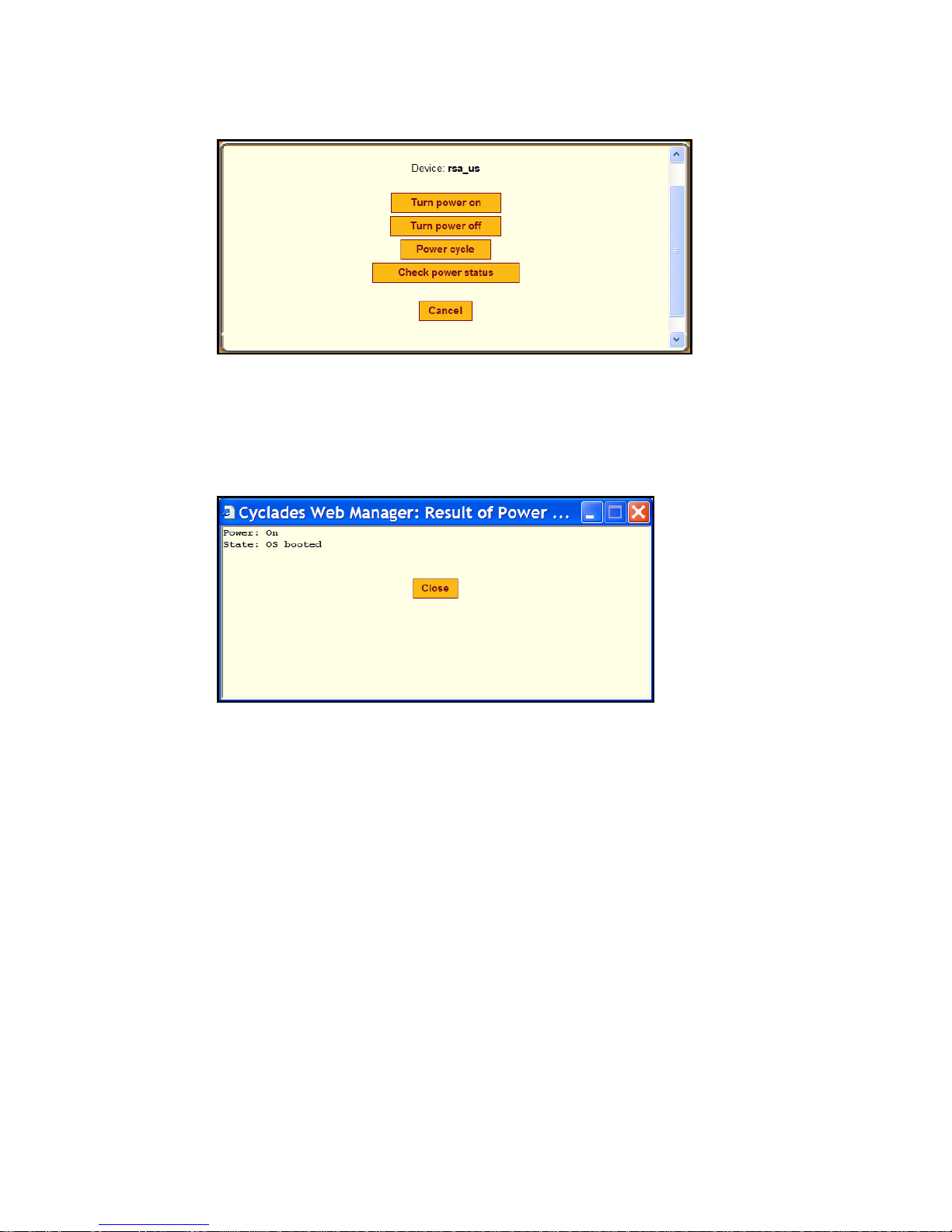
Managing Power Through a Service Processor
Figure 2-6: Power Web Manager Screen
Clicking the “Check power status” button brings up a dialog box that shows
the server’s power status. The following screen example shows the power is
on and the operating system (OS) is booted on the server.
Figure 2-7: Example Power Status Dialog
T To Manage a Server’s Power Through a
Service Processor [Web Manager]
1. Bring up the Web Manager and log in.
See “To Log Into the Web Manager” on page 43, if needed.
2. From the list of devices that displays on the “Devices” screen, click the
“Power” link that is associated with the server whose power you want to
manage.
3. To turn power on for the server, click the “Turn power on” button.
4. To turn power off for the server, click the “Turn power off” button.
50 Alter Path OnBoard User’s Guide
Page 71

Running Reset on a Service Processor
5. To turn power off and then on for the server (to reboot the server), click
the “Power cycle” button.
6. To check the power status of the server, click the “Check power status”
button.
Running Reset on a Service Processor
If a service processor has more than one type of reset option, the OnBoard
“Reset” command on the Devices screen performs the highest level of reset:
the cold boot option if available. See “What the Reset Command Does on
Different Servers” on page 18 for details.
T To Reset a Server from a Service Processor
[Web Manager]
1. Bring up the Web Manager and log in.
See “To Log Into the Web Manager” on page 43, if needed.
2. From the list of devices that displays on the “Devices” screen, click the
“Reset” link associated with the server.
Viewing Sensor Data
Clicking the “Sensors” button on the Devices screen displays the service
processor’s sensor plotting page. The following screen example shows the
message that comes up while the sensor information is being loaded. For
details about the “Sensor Plotting” on page 27.
Web Manager for Authorized Users 51
Page 72
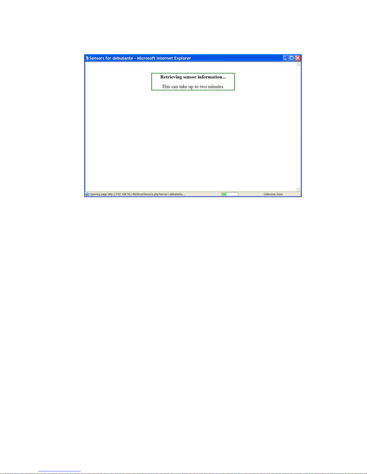
Viewing Sensor Data
Figure 2-8: Sensors Data Loading Message
The following screen example shows the Sensors screen that displays
unformatted data.
52 Alter Path OnBoard User’s Guide
Page 73
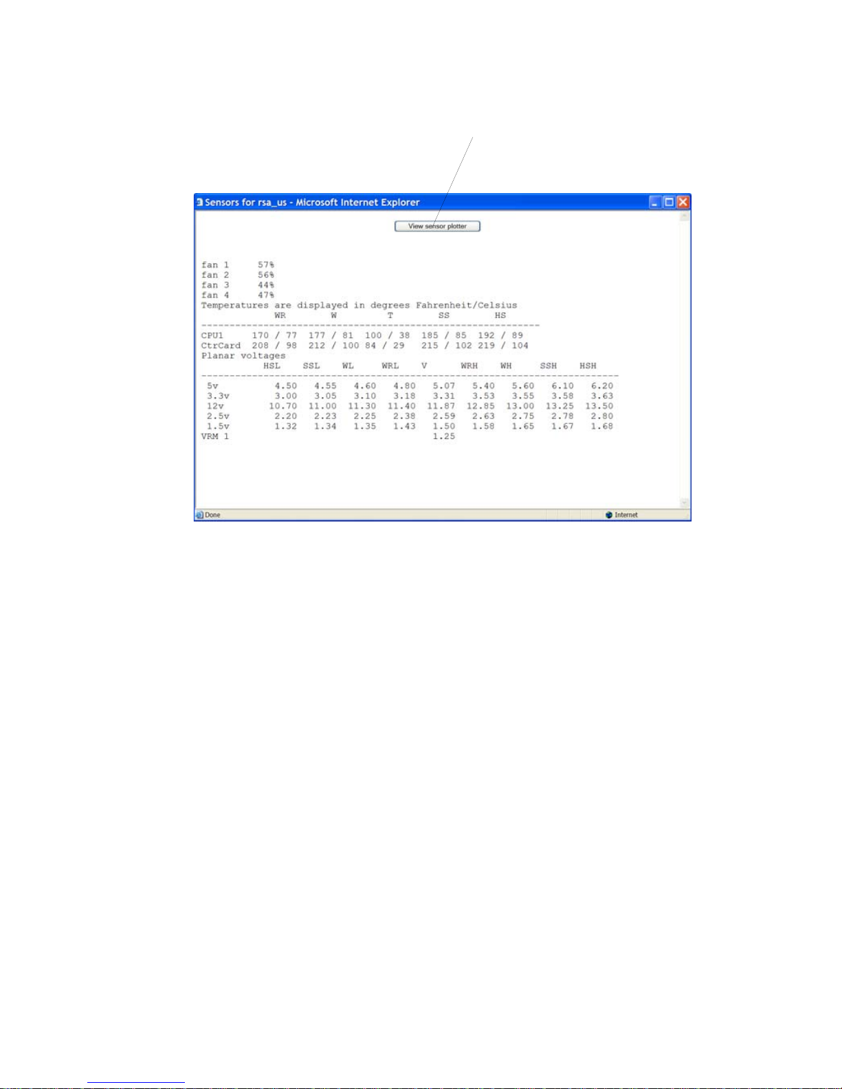
Viewing Sensor Data
View sensor plotter button
Figure 2-9: Example of Unformatted Sensor Data
Clicking the “View sensor plotter” button shown in Figure 2-6 brings up a
screen that allows you to view data from individual sensors on the server.
The sensor plotter page is shown in the following screen example. Callouts
indicate the list of sensors in the left column with a radio button next to each
item; the graph area; and the “Display Graph” button. After the radio button
next to the desired sensor is clicked, clicking “Display Graph” displays the
data from the selected sensor in the graph area.
Users can bring up multiple instances of the sensor plotter page and view
different sensors in different graphs at the same time.The graph displays a
new reading at a specified interval. The default is five seconds. You can
change the interval.
See Table 2, “Sensor Graph Parameters,” on page 28 for descriptions of the
defaults and allowed values you can specify to change the display.
The following figure shows the default graph format.
Web Manager for Authorized Users 53
Page 74
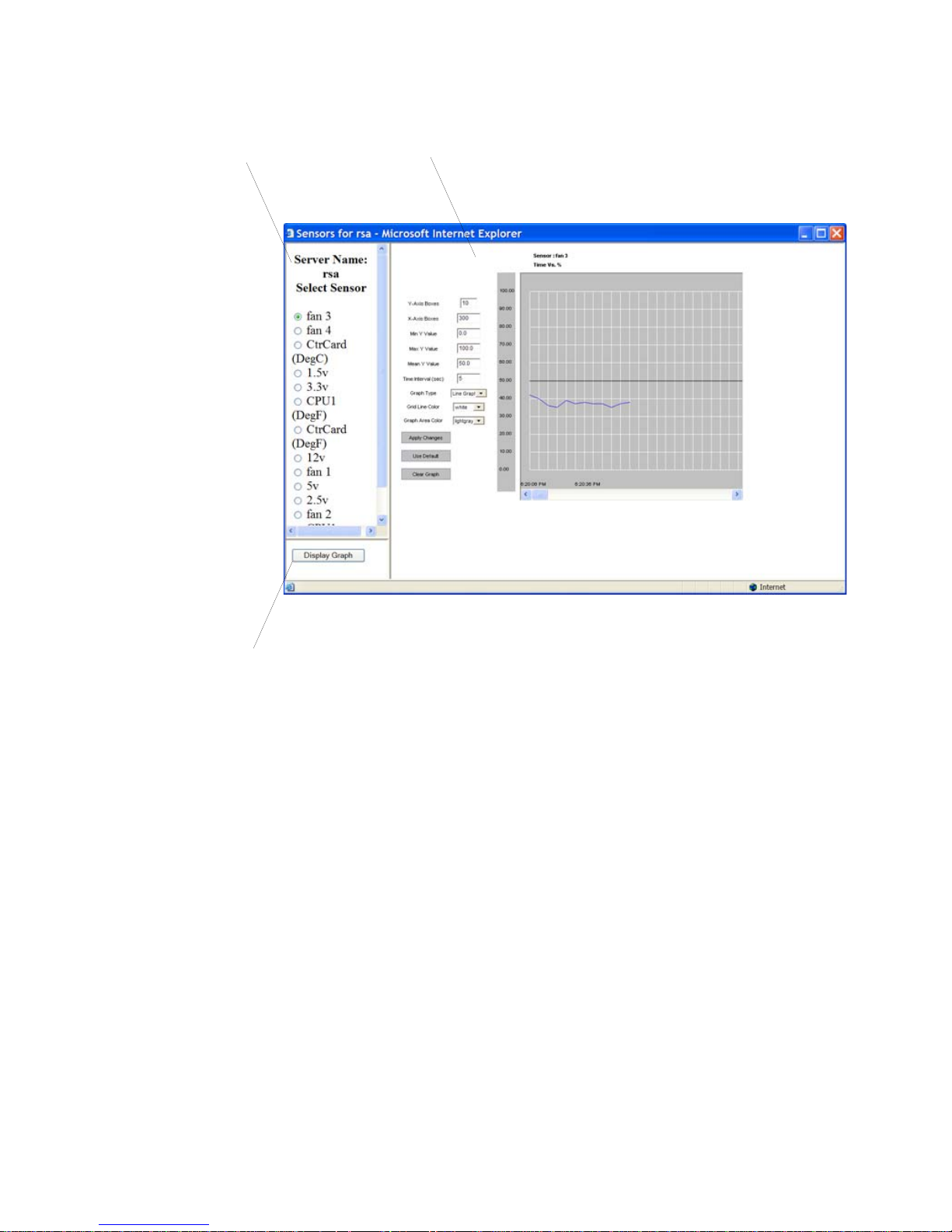
Viewing Sensor Data
Sensors list Graph area
“Display Graph” button
Figure 2-10:Graph Example
T To View a Server’s Sensor Data from a
Service Processor [Web Manager]
1. Bring up the Web Manager and log in.
2. From the list of devices that displays on the “Devices” screen, click the
3. Click the “View sensor plotter” button.
4. Click the radio button next to the name of the sensor you want to view.
See “To Log Into the Web Manager” on page 43, if needed.
“Sensors” link associated with the server whose sensors you want to view .
A MindTerm Java applet appears showing unformatted sensor data.
A list of sensors appears on the left with the main graph area empty.
5. Click the “Display Graph” button.
54 Alter Path OnBoard User’s Guide
Page 75

Viewing and Clearing Event Logs
A graph of data from the selected sensor displays in the default graph
format.
Viewing and Clearing Event Logs
Clicking the “Event Log” button on the Devices screen displays the system
event log (SEL) menu from the server where the service processor resides.
Event messages are sent by the service processor when system management
events are detected. The events may be being logged either by the service
processor or by the server. The “Clear event log” button appears at the top of
the screen, as shown in the following screen example.
Web Manager for Authorized Users 55
Page 76
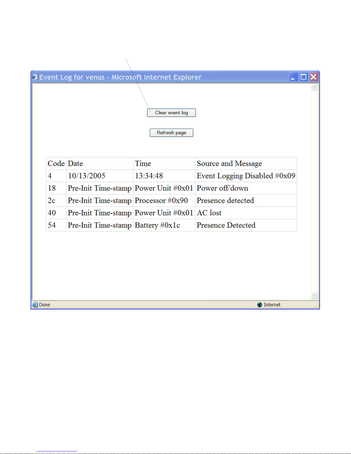
Viewing and Clearing Event Logs
“Clear event log” button
Figure 2-11:Example Event Log Web Manager Screen
Clicking the “Clear event log” button clears the log.
T To View or Clear a Server’s Event Log
Through a Service Processor [Web Manager]
1. Log into the Web Manager.
See “To Log Into the Web Manager” on page 43, if needed.
56 Alter Path OnBoard User’s Guide
Page 77
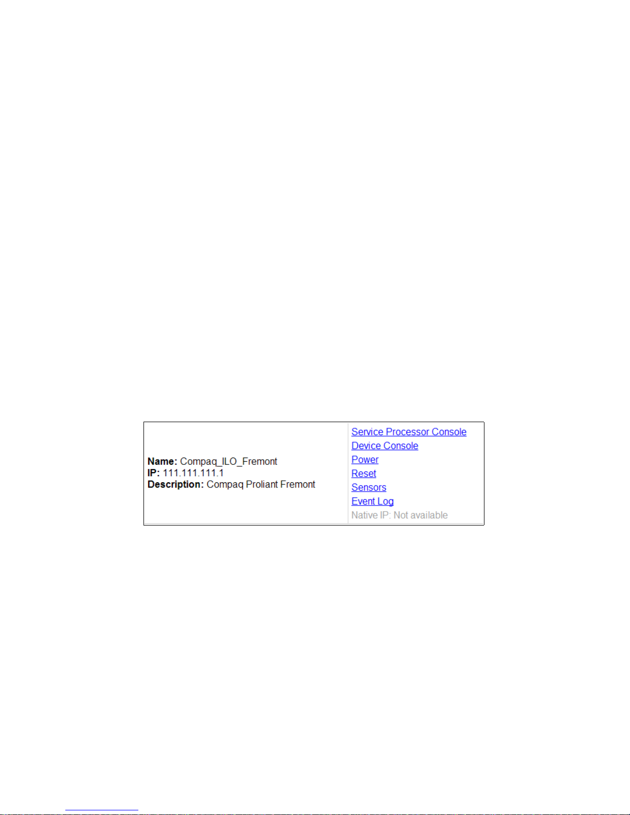
Accessing Native Features on a Service Processor
2. From the list of devices that displays on the “Devices” screen, click the
“Event log” link associated with the server whose power you want to
manage.
The Event log displays for your review.
3. To clear the event log click the “Clear event log” button.
Accessing Native Features on a Service
Processor
The Web Manager Access −> Device screen displays the “Enable Native IP”
option for a service processor only if the following are all true:
• The user is authorized for native IP access to the service processor,
• The device supports native IP access, and
• A VPN connection (tunnel) exists between the user and the OnBoard.
If a VPN connection is not already up, the Access
“Native IP: Not available” message, as shown in the following screen
example.
Figure 2-12:Native IP: Not Available Status
By clicking the “Enable” link next to “Native IP” on the Devices screen, an
authorized user enables access to several native features that may be available
on a service processor or device, including:
• A native web application
• A native management application
For more details, see “Accessing a Device’ s Native Management Features” on
page 24.
−> Device screen displays a
Web Manager for Authorized Users 57
Page 78

Accessing Native Features on a Service Processor
The rules for how the user brings up the Web Manager to access the Devices
screen differs between IPSec and PPTP VPN connections as indicated here:
• If the VPN connection is being made using IPSec, the authorized user
may use the OnBoard’s IP address to bring up the Web Manager first and
go to the Device screen before making the VPN connection. After
subsequently making the VPN connection, the user can reload the form to
see the Enable Native IP link active.
• If the VPN connection is made using PPTP, the VPN connection must be
made before the Web Ma nager can be launched, because the Web
Manager must be launched using the PPTP IP address.
The user obtains the IP address assigned to the PPTP interface by entering
the ifconfig or ipconfig command on the computer’s command
line (which command to use depends on the operating system). In the
command output, the IP address assigned to the connection appears next
to the words “PPP adapter.”.
C:\> ipconfig
...
PPP adapter OnBoard_PPTP_VPN
...
IP Address. . . . . . . . . . : 172.0.0.0.100
...
The user then enters the PPTP IP address in a browser to bring up the Web
Manager and enable Native IP access.
See “Tasks for Creating Secure Tunnels and Obtaining Native IP Access” on
page 26 for more details.
58 Alter Path OnBoard User’s Guide
Page 79
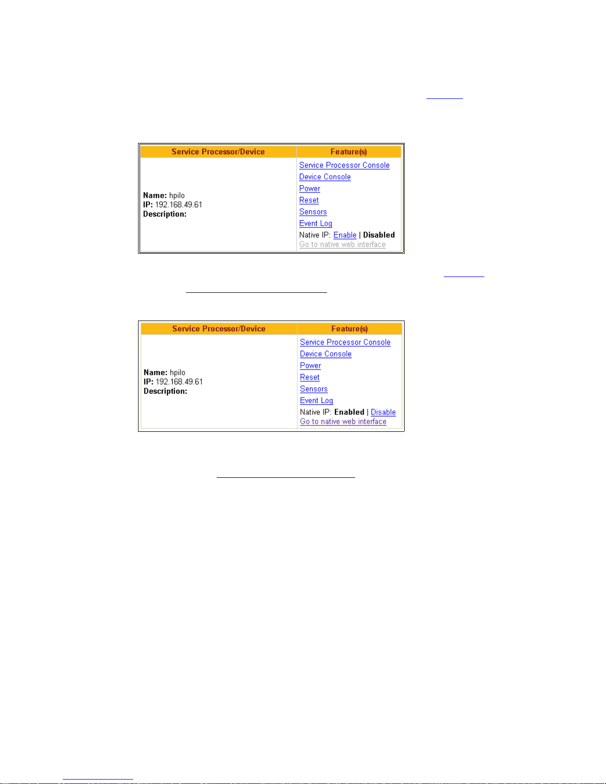
Accessing Native Features on a Service Processor
As shown in the following screen example, the words Enable | Disabled
appear appears next to the Native IP option if a VPN connection exists, with
the Enable link active.
Clicking the Enable link enables native IP and makes the Disable
and the “Go to native web interface
” link appears, as shown in the following
link active
screen example.
The authorized user can then do one of the following:
• Click the “Go to native web interface
” link to launch a browser that brings
up the native web application on the service processor.
• Launch a service processor management application from the user’s
remote computer.
The following figure shows an example of a HP iLO web interface that
appeared after an authorized user clicked the “Go to native web interface” link
shown in the previous figure.
Web Manager for Authorized Users 59
Page 80
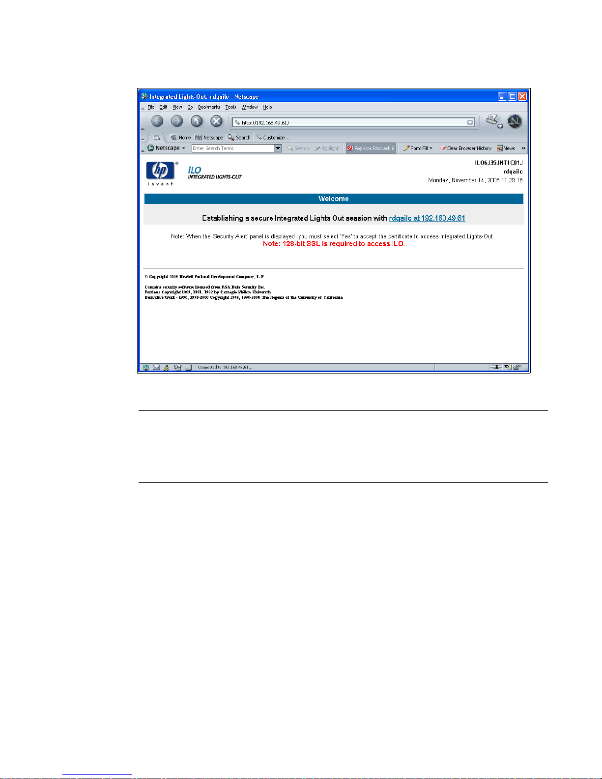
Accessing Native Features on a Service Processor
Figure 2-13:Example HP iLO Native Web Interface
Caution! When finished with service processor management tasks
performed using native IP, the authorized user should always click the
“Disabled” link before closing the VPN connection. Leaving native IP
enabled creates a security risk.
T To Create a PP TP VPN Connection Profile on
Windows—Example
This procedure assumes the following prerequisites:
• You are running Windows NT on your remote computer.
If you are running any other Windows operating system, follow these
steps as an example.
• The OnBoard administrator has done all of the following:
• Authorized your OnBoard user account for PPTP access.
60 Alter Path OnBoard User’s Guide
Page 81

Accessing Native Features on a Service Processor
• Provided you with the PPTP password if it is different from your
OnBoard password.
• Enabled the PPTP service.
• Configured the OnBoard for VPN PPTP connections
• Provided you with an IP address that was assigned while configuring
VPN PPTP access on the OnBoard.
1. Login in as an administrator on Windows NT.
2. From the start menu, go to My Network Places
connections
−> Create a new connection.
−> view network
The “New Connection Wizard” appears.
3. Click the “Next” button.
4. On the next dialog that appears, click the radio button next to “Connect to
the network at my workplace.”
5. Click the “Next” button.
6. On the next dialog that appears, click the radio button next to “Virtual
Private Network connection.”
7. Click the “Next” button.
8. On the next dialog that appears, enter a name for the connection.
9. Click the “Next” button.
10. If the “Public Network” dialog appears, click the radio button next to “Do
not dial the initial connection.”
11. On the next dialog that appears, for the “VPN Server Selection,” enter an
IP address.
Note: The IP address is the one assigned to the public interface of the
OnBoard.
12. Click the “Next” button.
13. Click the “Finish” button.
Web Manager for Authorized Users 61
Page 82

Accessing Native Features on a Service Processor
T To Enable Access to Native Features on a
Device [Web Manager]
1. Create a VPN tunnel between your computer to the OnBoard.
If you created a VPN connection profile, click the name of the connection
profile to create the connection.
2. If the VPN connection was made using IP Sec, brin g up the Web Manager
by entering in a browser the IP address that is assigned to the OnBoard’s
public interface.
3. If the VPN connection was made using PPTP, obtain and use the IP
address that is assigned on your computer to the PPTP interface.
a. If your computer has a Windows operating system, enter the
ipconfig command on the computer’s command line.
b. If your computer has a UNIX-based operating system, enter the
ifconfig command on the computer’s command line.
c. In the command output, locate the IP address assigned to the
connection.
The following screen example shows the PPTP interface IP address
output from the ipconfig command on an Windows NT operating
system.
C:\> ipconfig
...
PPP adapter OnBoardPPTPVPN
...
IP Address. . . . . . . . . . : 172.0.0.0.100
...
d. Enter the PPTP IP address in a browser to bring up the Web Manager.
4. Log into the Web Manager and go to Devices screen.
5. From the list of devices that displays on the “Devices” screen, click
“Enable
native IP access.
” next to the “Native IP” link for the device on which you want
The “Go to native web interface
62 Alter Path OnBoard User’s Guide
” link becomes active.
Page 83
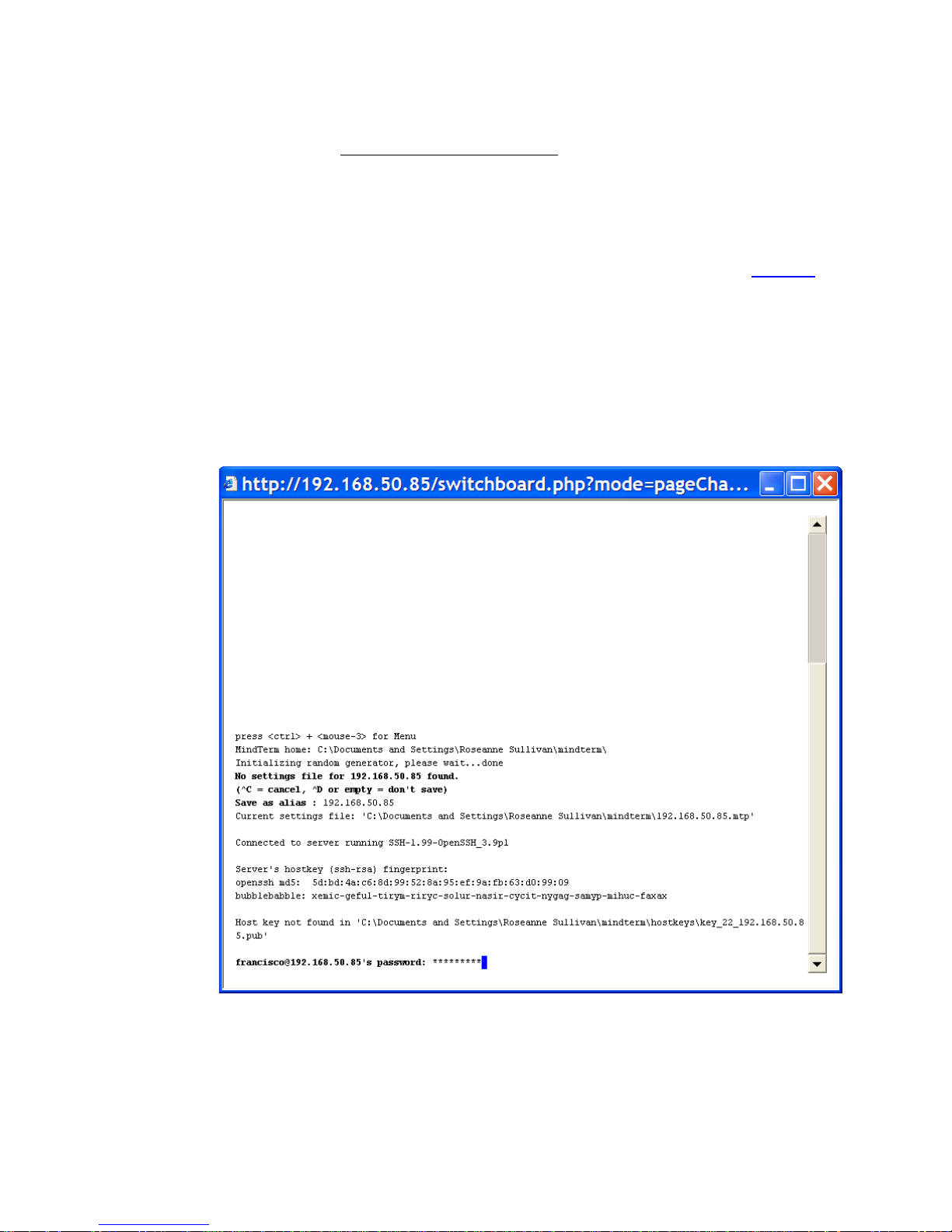
Accessing the OnBoard Console [Web Manager]
6. Click the “Go to native web interface” link to launch a browser that brings
up the native web application on the service processor.
7. From your local computer , launch a previously-installed service processor
management application for the server, if desired.
8. Essential security precaution: When you are done, click the Disable
link.
Accessing the OnBoard Console [Web Manager]
Clicking the OnBoard option on the Web Manager menu and clicking the
“Connect to OnBoard” button brings up a window running a MindTerm Java
applet with an ssh connection to the OnBoard, as shown in the following
screen example.
Figure 2-14:OnBoard Console Login Screen
Regular users by default are not able to access the OnBoard’s shell, and they
cannot do anything on the OnBoard’s console that they could not do from the
Web Manager for Authorized Users 63
Page 84
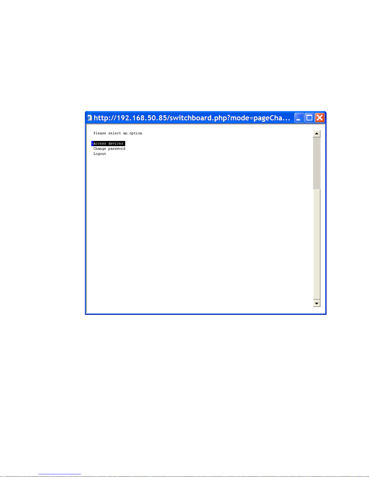
Accessing the OnBoard Console [Web Manager]
Web Manager menu options. Users are encouraged to use the Web Manager
instead of going through it and using the console.
After authentication, the regular user sees the two following choices to access
devices or change the user’ s password, which are similar to the Web Manager
menu options.
Figure 2-15:User Menu When Connected to the OnBoard’s Console
For information about what the administrative user can do on the OnBoard
console, see AlterPath OnBoard Administrator’s Guide.
T To Access the OnBoard’s Console [Web
Manager]
1. Bring up the Web Manager and log in.
See “To Log Into the Web Manager” on page 43, if needed.
64 Alter Path OnBoard User’s Guide
Page 85
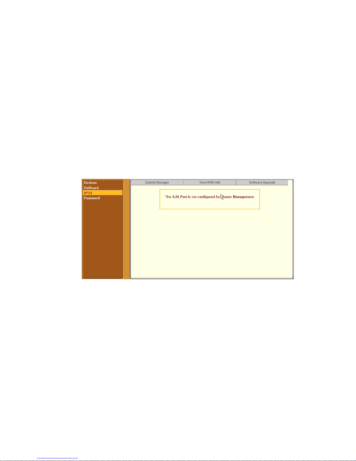
Managing Power Outlets on a Connected IPDU
2. Click the “OnBoard” option in the left menu.
A terminal window displays and establishes a console connection to the
OnBoard.
3. Enter the password, if prompted.
A menu of options displays for the regular user. For an administrative user
a shell prompt appears.
Managing Power Outlets on a Connected IPDU
Clicking the IPDU option on the Access menu brings up the message shown
below if the AUX port has not been configured for IPDU power management.
Contact the OnBoard administrator for help if you see this message.
Clicking the IPDU option on the Access menu when the AUX port has been
configured for IPDU power management brings up three tabs, as shown in the
following screen example.
Web Manager for Authorized Users 65
Page 86
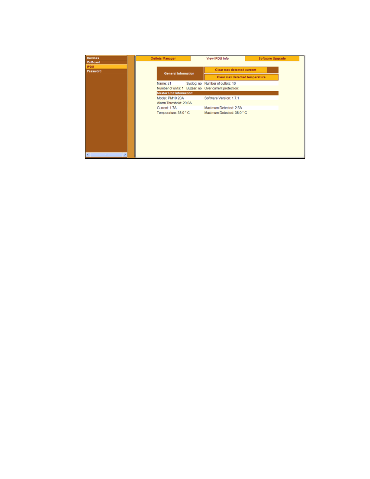
Managing Power Outlets on a Connected IPDU
Figure 2-16:IPDU Tabs
Authorized users can access the screens under the three tabs to manage power
on the outlets and to view information about the IPDUs. Administrative users
can additionally assign names and set the power up interval for outlets and can
upgrade software on the IPDU as described in the AlterPath OnBoard
Administrator’s Guide.
The three tabs are listed below with links to where they are described:
• Outlets Manager
See “Using the Outlets Manager Tab to Turn Power On and Off and
Check Power Status” on page 66.
• View IPDUs Info
See “Viewing IPDU Information” on page 69.
• Software Upgrade
The regular user can only view this screen.
Using the Outlets Manager Tab to Turn Power On
and Off and Check Power Status
If a regular user clicks the “Outlets Manager” tab under Access −> IPDU, the
message shown in the following figure appears if the user is not authorized to
manage power on any outlets, or if the OnBoard cannot detect an AlterPath
PM connected to the AUX port. Contact the OnBoard administrator for help if
you see this message.
66 Alter Path OnBoard User’s Guide
Page 87
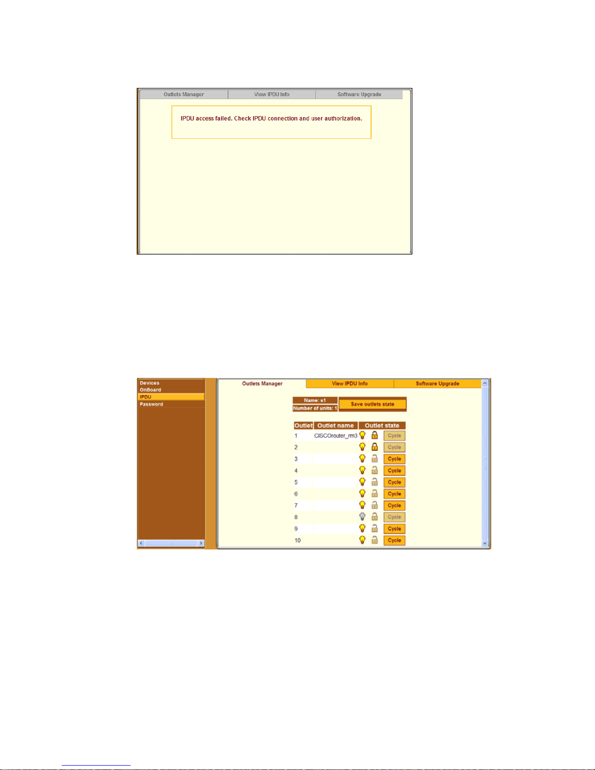
Managing Power Outlets on a Connected IPDU
Figure 2-17:IPDU Access Failed Message from “Outlets Manager”
If a regular user clicks the “Outlets Manager” tab under Access
−> IPDU, the
screen displays a list of all the outlets the user is authorized to manage. If an
administrative user clicks on Outlets Manager under Access
−> IPDU, all the
power outlets on all connected IPDUs are listed, as shown in the following
figure.
[
Figure 2-18:Access
−> IPDU −> Outlets Manager Screen
Both regular users who are authorized for IPDU power management and
administrative users can do the following for any of the listed outlets:
• Cycle (turn power briefly off and then on again to reboot the server).
• Lock outlets in the on or off state to prevent accidental changes
• Unlock the outlets
• Turn power off
Web Manager for Authorized Users 67
Page 88
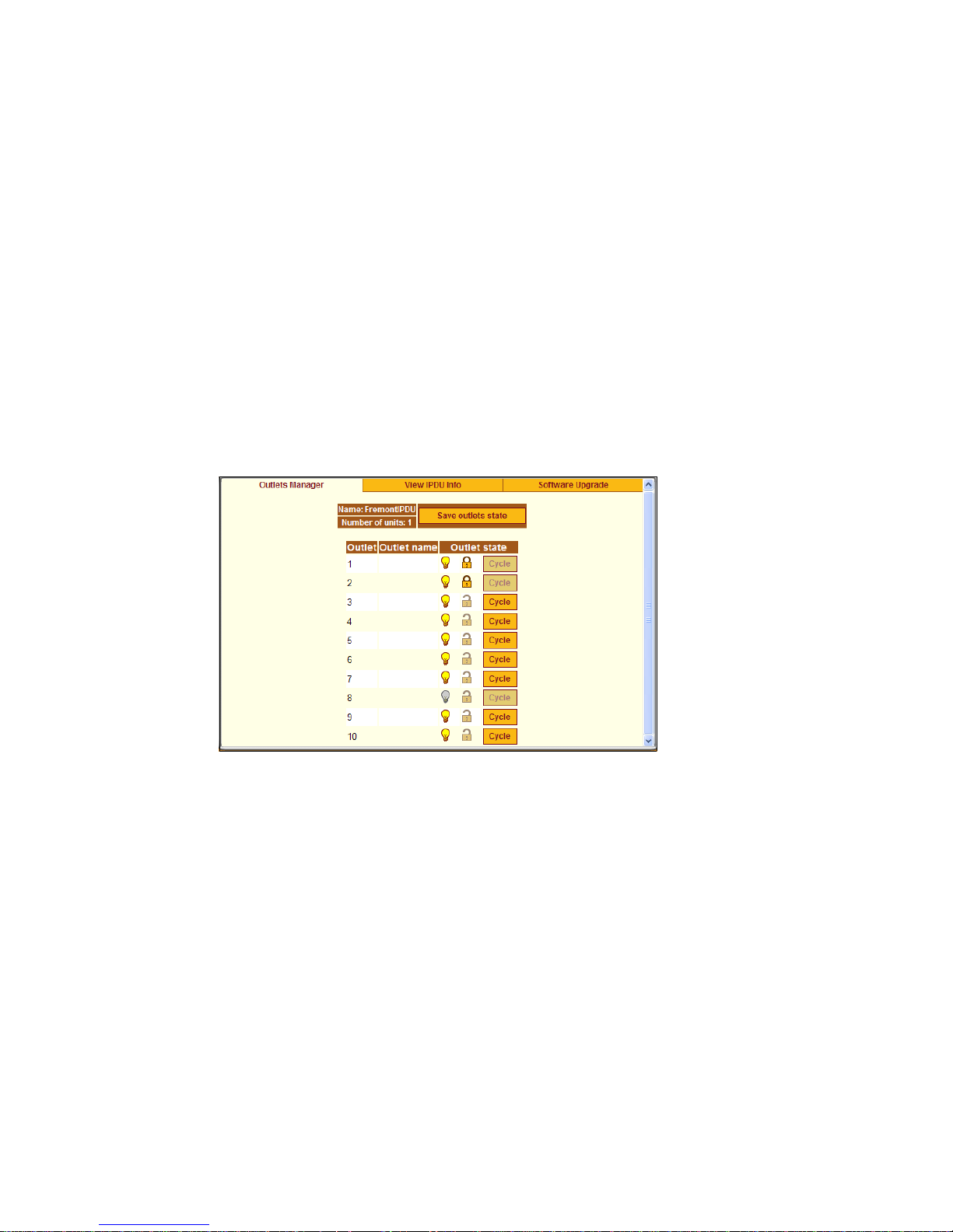
Managing Power Outlets on a Connected IPDU
• Turn power on
• Save any changes made to the outlets state
The Name that appears on the screen is either the default “s1,” which is the
port number of the AUX port; or an administrator-specified name. A yellow
bulb indicates that the outlet’s power is on. A gray bulb indicates that the
outlet’s power is off. An open padlock indicates that the outlet is unlocked. A
closed padlock indicates that the outlet is locked. An orange “Cycle” button is
active next to each outlet that is on; the “Cycle” button is grayed when the
outlet is off. The “Save outlets state” button allows the user to save any
changes made on this screen.
In the example below , all outlets are switched on except outlet 8, outlets 1 and
2 are locked and outlets 3 through 8 are unlocked.
Figure 2-19:Outlets Manager Outlets State Close-up
T To Manage Power Outlets on a Connected
IPDU
1. Bring up the Web Manager and log in.
See “To Log Into the Web Manager” on page 43, if needed.
2. Click the “IPDU” option in the left menu.
The IPDU screen displays with the “Outlets Manager” screen active.
3. To switch an outlet on or off, click the adjacent light bulb.
4. To lock or unlock an outlet, click the adjacent padlock.
68 Alter Path OnBoard User’s Guide
Page 89
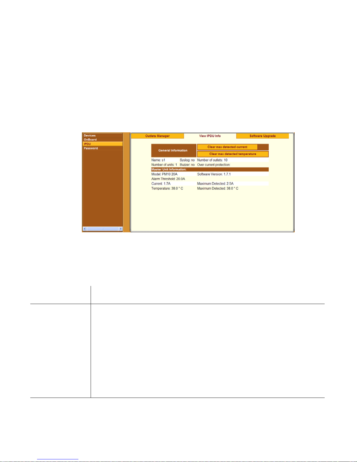
Managing Power Outlets on a Connected IPDU
5. To momentarily power an outlet off and then on again, click the adjacent
“Cycle” button.
6. To save the state of the outlet(s), click “Save Outlets State.”
Viewing IPDU Information
When a regular user or admin goes to Access −> IPDU −> View IPDU Info, a
screen appears like the one shown in the following figure.
Figure 2-20:View IPDU Info Screen
The following table shows the information displayed on the “View IPDU
Info” screen for each IPDU.
Table 2-4: Information on the View IPDU Info Screen
Description Example
Name
Administrator-configured name or the default (s1),
which is assigned to the AUX port.
Number of
units
The number of IPDUs connected to the port. The first
IPDU is referred to as the master. Any other IPDUs
daisy-chained off the first IPDU are referred to as
slaves.
Number of
Total number of outlets on all connected IPDUs. 10
outlets
FremontIPDU
1
Web Manager for Authorized Users 69
Page 90

Managing Power Outlets on a Connected IPDU
Table 2-4: Information on the View IPDU Info Screen
Description Example
Buzzer
Syslog
Over current
protection
Model
Whether a buzzer has been configured to sound when
no
a specified alarm threshold is exceeded.
Whether syslogging has been configured for messages
no
from this IPDU.
Whether over current protection is enabled (to prevent
outlets from being turned on if the current on the
IPDU exceeds the specified threshold).
BUG? This is
empty but it
should show a
value, either
yes or no.
You can view the following information about each IPDU (under Unit
Information)
Description Example
AlterPath PM model number PM10
20A
Software Version
Alarm Threshold
PM firmware version 1.7.1
Number of amperes that triggers an alarm or syslog
20.0A
message if it is reached
Current
Maximum
Current level on the IPDU 1.7A
Maximum current detected 2.5A
Detected
Temperature
Temperature on the AlterPath PM (only available on
37.0° C
selected models that have temperature sensors)
Maximum
Maximum temperature detected 37.0° C
Detected
70 Alter Path OnBoard User’s Guide
Page 91
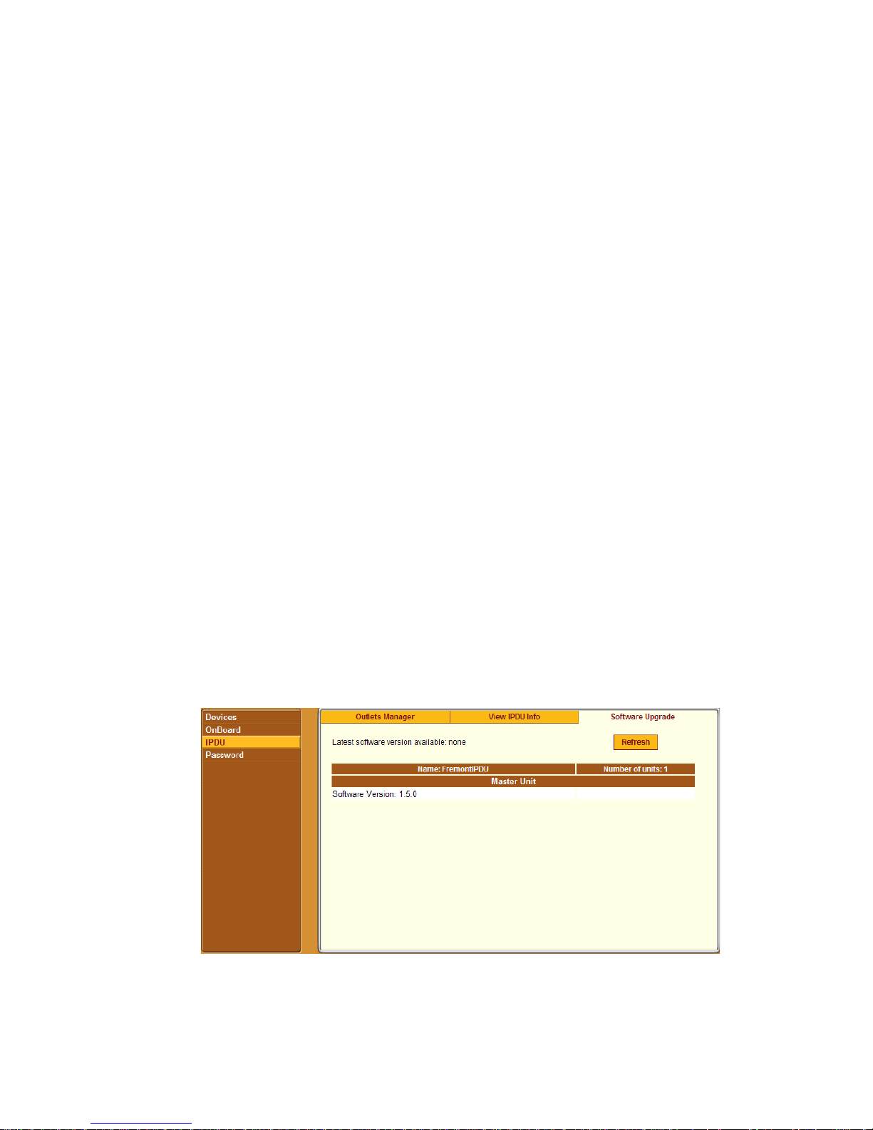
Managing Power Outlets on a Connected IPDU
The following three buttons are also displayed on the screen:
• “Clear max detected current”
• “Clear max detected temperature”
T To View IPDUs Information
1. Bring up the Web Manager and log in.
See “To Log Into the Web Manager” on page 43, if needed.
2. Click the “IPDU” option in the left menu.
The IPDU screen displays.
3. Click the “View IPDU Info” tab
4. If desired, clear the “Maximum Detected” value displayed for current by
clicking the “Clear max detected current” button.
5. If desired, clear the “Maximum Detected” value displayed for
temperature by clicking the “Clear max detected temperature” button.
Using the “Software Upgrade” Screen to V iew the
IPDU’s Current Software Version
The admin user can use this screen to upgrade software on a connected
AlterPath PM IPDU. Regular users can use this screen only to view the
software version.
Figure 2-21:IPDU “Software Upgrade” Screen on the Web Manager
Web Manager for Authorized Users 71
Page 92
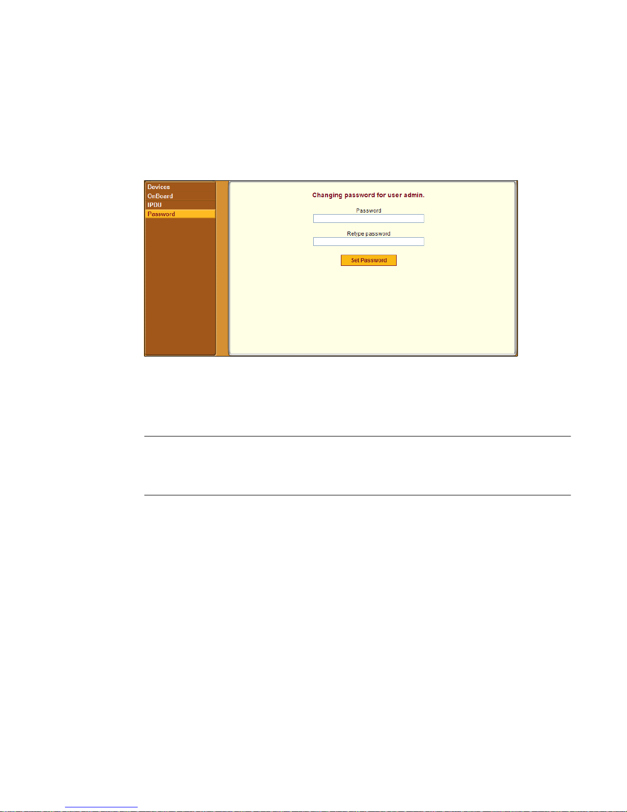
Configuring Your Password
Configuring Your Password
Clicking the “Password” option on the Web Manager left menu brings up the
“Changing password for username” screen, as shown in the following screen
example.
Figure 2-22:“Password” Screen
After the password is entered, clicking “Set Password” saves the changes in
memory.
Note: Your password cannot exceed 30 characters. For security, follow
commonly available guidelines to create passwords that are not easily
guessed.
T To Change Your Password
1. Bring up the Web Manager and log in.
See “To Log Into the Web Manager” on page 43, if needed.
2. Click the “Password” option in the left menu.
The Password screen displays.
3. Enter the new password in the “Password” field.
4. Enter the password again in the “Retype password” field.
5. Click the “Set Password” button.
72 Alter Path OnBoard User’s Guide
Page 93

Chapter 3
Accessing the OnBoard and
Connected Devices
This chapter provides information about how authorized users and
administrators can access the OnBoard and connected devices in the
following ways:
• Use the Web Manager or the ssh command to access the OnBoard’s
console and use menu options to change passwords and perform device
management actions
• Use the ssh command with OnBoard-specific device management
options to perform device management actions on connected devices
• Access native IP management features on connected devices through the
following types of tunnels:
•VPN
• SSH
This chapter describes the following topics.
Accessing the OnBoard’s Console Page 75
Accessing Device Management Features From the OnBoard’s Console Menu Page 77
Accessing the Console of a Device Through the OnBoard’s Console or By
Using SSH
Obtaining and Using One Time Passwords for Dial-ins Page 97
This chapter provides the procedures listed in the following table.
To Access the OnBoard’s Console Page 76
To Use a SSH Command to Connect Directly to a Device’s or Service
Processor’s Console
Page 79
Page 80
To Use OnBoard’s Console Menus to Access the Device Management Options Page 81
To Exit from a Console Session Page 82
73
Page 94

To Use OpenSSH on Linux to Create an SSH Tunnel Page 83
To Use PuTTY on a Windows PC to Create an SSH Tunnel Page 83
To Bring Up a Native Web Application When an SSH Tunnel Exists Page 85
To Create an IPSec VPN Tunnel Page 92
To Enable Native IP Access Through an IPSec VPN Tunnel Page 92
To Create a PPTP VPN Tunnel Page 93
To Enable Native IP Access Through a PPTP VPN Tunnel Page 94
To Access a Native We b Application When a VPN Tunnel Exists Page 94
To Access a Native Management Application Page 95
To Generate an OTP Password When Challenged at Dial-in Page 98
74 Alter Path OnBoard User’s Guide
Page 95

Accessing the OnBoard’s Console
Accessing the OnBoard’s Console
As described under “Accessing the OnBoard’s Console” on page 12,
administrators and authorized users can access the OnBoard’s console through
either of the following two ways:
• Through a directly-connected terminal or computer that is running a
terminal emulation program
• By initiating an ssh connection from the user’s workstation
To use the ssh command from the user’s workstation, the user enters the
username followed by a colon and an at sign (:@) followed by the DNS name
or the IP address assigned to the OnBoard, either with or without the
rmenush command, as shown in the following screen example.
% ssh username:@onboard_IP_or_DNS_name
% ssh -t username:@onboard_IP_or_DNS_name
rmenush
Both of the commands shown in the previous screen example give the nonadministrative user access to the same menu.
Regular users need to obtain the IP address from the OnBoard administrator.
When root or admin or another administrative user logs in through the console
entering the first command line above without the rmenush command, the
prompt for the unrestricted shell appears. With the rmenush command, the
administrative user sees the rmenush menu.The following screen example
shows the shell prompt for the root user.
[root@OnBoard root]#
The following screen example shows the menu.
-Access Devices
Change Password
Logout
See “Accessing the OnBoard Using SSH” on page 21 for an overview of the
format of the ssh command and other command options, if desired.
See “User Shell (rmenush)” on page 13 for details about the menu options.
See the following procedure for how to access the OnBoard’s console.
Using OnBoard Console Menus and SSH Commands 75
Page 96

Accessing the OnBoard’s Console
T To Access the OnBoard’s Console
This procedure requires the following prerequisites in order for anyone to be
able to access the command line using SSH.
• The user must know the IP address of the OnBoard
• The user must know a username and password for a user account
configured on the OnBoard.
1. To use a terminal or terminal emulation program installed on a computer
that is physically connected to the console port of the OnBoard, start the
terminal session with the following factory-default console port settings.
Serial Speed: 9600
bps
2. To use an SSH applicat ion or the ssh command from a remote location,
3. Log into the OnBoard when prompted.
Parity:
None
Flow Control:
None
Data Length: 8
bits
Stop Bits: 1ANSI
emulation
enter the username followed by a colon and an at sign (:@) followed by
either the DNS name or the IP address assigned to the OnBoard, as shown
in the following screen example.
% ssh username:@onboard_IP_or_DNS_name
The screen example shows entering the ssh command on the command
line, using francisco as the username and 192.168.44.111 as the IP
address.
% ssh francisco@:192.168.44.111
After authentication and login, for administrative users (root, admin, or
additional users who are members of the admin group) a shell prompt
appears. For authorized non-administrative users, the user shell menu
appears.
76 Alter Path OnBoard User’s Guide
Page 97

Accessing Device Management Features From the OnBoard’s Console Menu
Accessing Device Management Features From
the OnBoard’s Console Menu
After logging in as described in “Accessing the OnBoard’s Console” on page
75, non-administrative users see a menu similar to the menu shown in the
following screen example.
-Access Devices
Change Password
Logout
Figure 3-1: User Shell Menu
The OnBoard administrator may configure the menu with other options. For
an example, see “Obtaining and Using One Time Passwords for Dial-ins” on
page 97, where an option for accessing the one time password menu has been
added.
Administrative users can see the same menu by entering /usr/bin/
rmenush on the shell’s command line.
A user move from one item to another on the menu and submenus by using
the keyboard’s arrow keys. A line (-) appears next to the selected item.
After an option is selected, pressing the “Enter” or “Return” key brings up a
submenu or runs the selected command.
If the “Access Devices” option is selected, a menu appears with a list of
devices that the user is authorized to access, as shown in the following screen
example.
Using OnBoard Console Menus and SSH Commands 77
Page 98
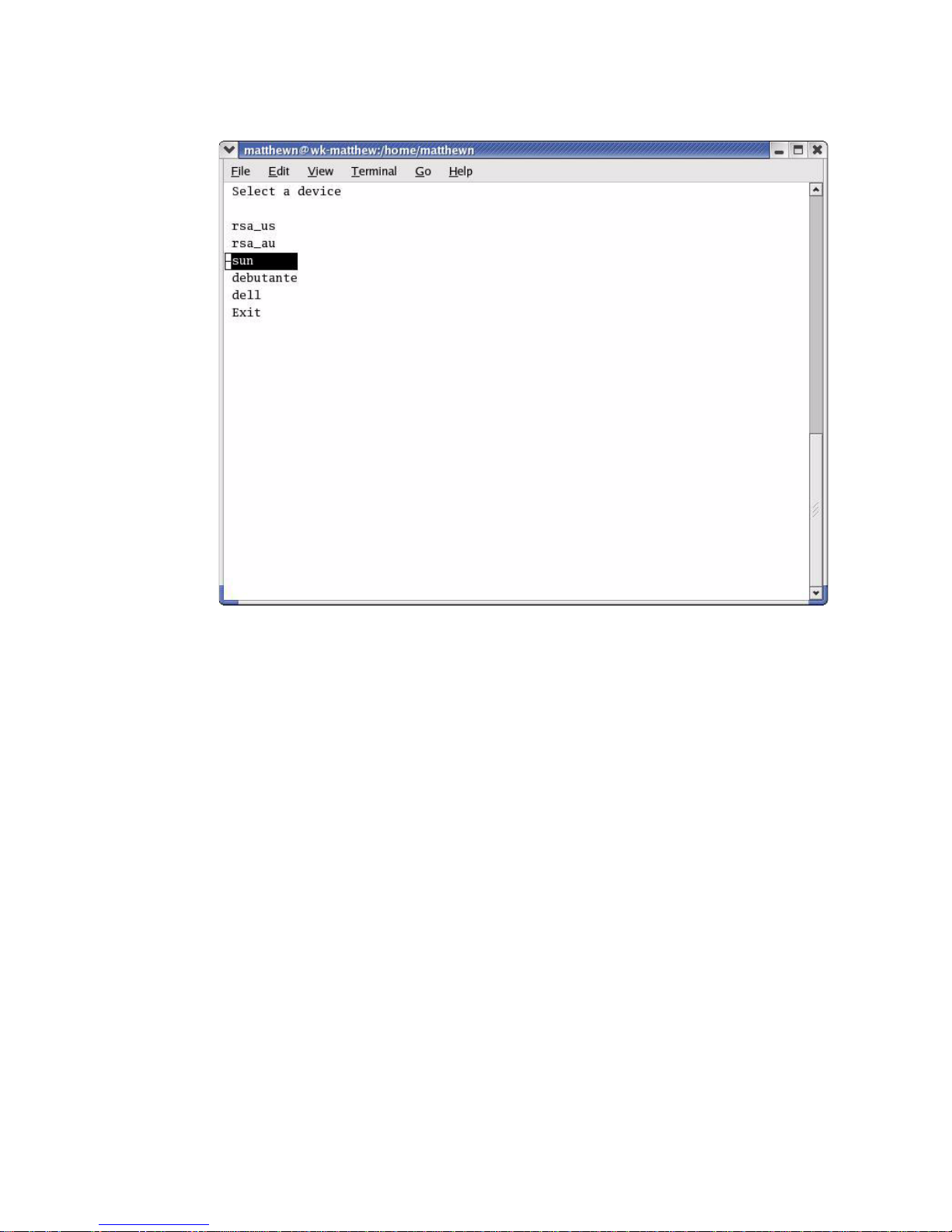
Accessing Device Management Features From the OnBoard’s Co nsole Menu
Figure 3-2: Device Access Menu
Administrative users can see a similar menu listing all configured devices by
entering /usr/bin/onbdshell on the shell’s command line.
After a device is selected, pressing the “Enter” or “Return” key brings up the
list of actions the user is authorized to perform on the device. Not all listed
actions are supported for all service processors.
Figure 3-3 shows the service processor “action” menu for an rsa-type service
processor.
78 Alter Path OnBoard User’s Guide
Page 99

Accessing the Console of a Device Through the OnBoard’s Console or By Using SSH
rsa_au
Access the service processor's
console
Access the device's console
Manage power
Reset
Manage the event log
Enable native IP
Disable native IP
E x i t
Back
Figure 3-3: Service Processor Action Menu
Accessing the Console of a Device Through the
OnBoard’s Console or By Using SSH
Any type of authorized user can access the console of a connected service
processor, server, or device using one of the two following means:
• Invoking the ssh command along with one of the two following
OnBoard-specific device management commands:
• spconsole
• devconsole
See “Device Management Commands for Use With SSH” on page 21 for
the format of the ssh command line when a device management
command is used, if desired.
• Connecting to the OnBoard’s console and selecting one of the following
menu options
• Access the service processor's console
• Access the device's cons ole
Using OnBoard Console Menus and SSH Commands 79
Page 100

Accessing the Console of a Device Through the OnBoard’s Console or By Using SSH
T To Use a SSH Command to Connect Directly
to a Device’s or Service Processor’s Console
This procedure assumes the following are true:
• You have access to the ssh command on the command line of your
computer
• You know the user name and password of an OnBoard user account that is
authorized to access the console of a device or service processor.
• You know the alia s of the device that allows console access.
• You know the IP address or DNS name of the OnBoard.
Enter ssh with the -t option followed by the username, followed by a
colon (:), followed by the alias, followed by the “at” sign (@), followed by
the IP address of the OnBoard, followed by the devconsole or
spconsole command.
% ssh -t username:device_alias@onboard_IP_or_DNS_name \
[devconsole | spconsole]
1. To connect directly to the device’s console, use the ssh command with
the devconsole command.
The following screen example shows entering ssh with the username
francisco, the device alias rsa_au, the OnBoard IP address 192.168.44.111
and the devconsole command.
% ssh -t francisco:[email protected] devconsole
2. To connect directly to a service proce ssor’s console, use the ssh
command with the spconsole command.
The following screen example shows entering ssh with the username
francisco and the IP address 192.168.44.111 with the spconsole
command on the command line.
% ssh -t francisco:[email protected] spconsole
80 Alter Path OnBoard User’s Guide
 Loading...