

Page 1

Cybex Trazer®
Owner’s Manual
Cardiovascular Systems
Part Number LT-21411-4 C
Page 2

Page 3

Cybex Trazer®
Owner’s Manual
Cardiovascular Systems
Part Number LT-21411-4 C
Cybex® and the Cybex logo are registered trademarks of Cybex International, Inc.
Polar® is a registered trademark of Polar Electro Inc.
Trazer® is a registered trademark of Trazer Technologies Inc.
DISCLAIMER: Cybex International, Inc. makes no representations or warranties regarding the contents of this manual. We reserve
the right to revise this document at any time or to make changes to the product described within it without notice or obligation to notify
any person of such revisions or changes.
© 2010, Cybex International, Inc. All rights reserved. Printed in United States of America.
10 Trotter Drive Medway, MA 02053 • 888-462-9239 • 508-533-4300 • FAX 508-533-5183
www.cybexinternational.com • techhelp@cybexintl.com • LT-21411-4 C • September 2010
Page 4

Page 5

Table of Contents
Front Pages
About this Manual .................. iii
FCC Compliance Information ......... iii
1 Safety
Important Voltage Information ......... 1-1
Important Safety Instructions ......... 1-1
Warning Decals .................... 1-3
Input Ports ........................ 1-8
Explanation of Symbols Used ........ 1-8
Space Required .................... 1-9
2 Assembly and Setup
Warnings ......................... 2-1
Choosing and Preparing a Site ........ 2-1
Electrical Power Requirements ........ 2-2
Assembling the Trazer ............... 2-2
Testing the Operation ............... 2-18
Set Date and Time .................. 2-20
3 Operation
Intended Use ..................... 3-1
Using the Beacon .................. 3-2
Basic Movements .................. 3-4
Operation Guide.................... 3-4
Trazer Activities .................... 3-6
Administration & Reports ............. 3-15
Log In ............................ 3-17
Client Management ................. 3-18
SAP Editor ........................ 3-23
Admin Setup ...................... 3-26
Synchronize ....................... 3-27
Trazer Setup ...................... 3-30
On-Site Calibration ................. 3-31
Terms Used ....................... 3-33
Symbols Used ..................... 3-34
Targets ........................... 3-35
On-Screen Feedback ................ 3-36
Trazer Client Log ................... 3-37
Scorecard ........................ 3-38
Performance Analysis Report ......... 3-39
4 Preventive Maintenance
Warnings ......................... 4-1
Regular Maintenance Activities ........ 4-1
Cleaning Your Trazer ................ 4-2
Recharging Beacon Battery ......... 4-2
Replacing Beacon Battery ............ 4-3
Disposing of CPU Battery ............ 4-4
Environment ....................... 4-4
Storage ........................... 4-4
5 Customer Service
Contacting Service ................. 5-1
Serial Number ..................... 5-1
Return Material Authorization (RMA) .... 5-2
Damaged Parts .................... 5-3
Ordering Parts ..................... 5-3
Appendix A–Technical Specifications .... A-1
Page i
Page 6

Page ii
Page 7

About This Manual
A CD containing the Owner’s Manual is shipped with each unit. To purchase additional copies
of this manual or any other Cybex manual, please do one of the following:
• fax your order to 508-533-5183
• contact Cybex Customer Service at 888-462-9239
• or contact Cybex Customer Service at 508-533-4300
To contact Cybex with comments about this manual you may send email to
techhelp@cybexintl.com.
FCC Compliance Information
WARNING: Changes or modifications to this unit not expressly approved by the party
responsible for compliance could void the user’s authority to operate the
equipment.
This equipment has been tested and found to comply with the limits for a Class B digital
device, pursuant to Part 15 of the FCC Rules. These limits are designed to provide
reasonable protection against harmful interference in a residential installation. This equipment generates, uses and can radiate radio frequency energy and, if not installed and used
in accordance with the instructions, may cause harmful interference to radio communications.
However, there is no guarantee that interference will not occur in a particular installation. If
this equipment does cause harmful interference to radio or television reception (which can be
determined by turning the equipment off and on) the user is encouraged to try to correct the
interference by one or more of the following measures:
• Reorient or relocate the receiving antenna.
• Increase the separation between the equipment and receiver.
• Connect the equipment into an outlet on a circuit different from that to which the
receiver is connected.
• Consult the dealer or an experienced radio TV technician for help.
Page iii
Page 8

Page iv
Page 9

Cybex 760S Owner’s Manual
1 - Safety
IMPORTANT: Read all instructions and warnings before using the unit.
Important Voltage Information
Before plugging the unit into an electrical outlet, verify that the voltage requirements for your area
match the voltage of the unit that you have received. The power requirements for the unit include
a grounded circuit rated for 115 VAC +5%, 60 Hz, 1.6 amps, 1-Phase or 230 VAC +5%, 50 Hz, 1.6
amps, 1-Phase.
Important Safety Instructions
(Save These Instructions)
DANGER: To reduce the risk of electric shock, always unplug this unit from the electrical outlet
immediately after using it and before cleaning it.
WARNING: Serious injury could occur if these precautions are not observed. To reduce the risk
of burns, fires, electric shock or injury:
WARNING: Ensure that your ceiling height will accommodate the maximum jump height of each
user.
NOTE: The data and statistics displayed on the unit (including heart rate) are not to be used to make a
medical diagnosis from. Consult your physician.
User Safety Precautions
• Obtain a medical exam before beginning any exercise program.
WARNING: Heart rate monitoring systems may be inaccurate. Over exercise may result in serious injury
or death. If you feel faint stop exercising immediately.
• Stop exercising if you feel faint, dizzy, or experience pain and consult your physician.
• Obtain instruction before using. Lisez les instructions avant l’utilisation.
• Read and understand the Owner’s Manual and all warnings posted on the unit before using.
• Persons under the age of 18 must be supervised. Ne laissez pas sans surveillance les personnes
de moins de 18 ans.
• Use properly fitting athletic shoes during exercise.
• Flooring material should provide shock absorption and prevent slippage and/or falls.
• Ensure beacon belt is properly adjusted and secured.
• Ensure exercise area is free and clear of objects.
• Do not spill liquids on the unit.
• Report any malfunctions, damage or repairs to the facility.
• Replace any warning labels if damaged, worn or illegible.
Safety
Page 1-1
Page 10

Cybex 760S Owner’s Manual
Facility Safety Precautions
• Make sure all user and safety precautions are observed.
• Read the Owner’s Manual carefully before assembling, servicing or using the equipment.
• Make sure that all users are properly trained on how to use the equipment.
• Make sure that each machine is set up and operated on a solid level surface. Do not install
equipment on an uneven surface.
• Make sure there is enough room for safe access and operation of the equipment. See Space
Required section at the end of this chapter.
• Make sure movement area is free of obstructions.
• Perform regular maintenance checks on the equipment.
• Immediately replace worn or damaged components. If unable to immediately replace worn or
damaged components then remove from service until the repair is made.
• Do not attempt repairs, electrical or mechanical. Seek qualified repair personnel when servicing. If
you live in the USA, contact Cybex Customer Service at 888-462-9239. If you live outside the USA,
contact Cybex Customer Service at 508-533-4300.
• Disconnect all power before servicing the unit.
• Keep a repair log of all maintenance activities.
• Use only Cybex supplied components to maintain/repair the equipment.
• Do not use attachments for the unit unless recommended by Cybex.
• Do not operate the unit around or where aerosol (spray) or where oxygen products are being
used.
• Do not use the unit outdoors.
NOTE: It is the sole responsibility of the user/owner or facility operator to ensure that regular
maintenance is performed.
Safety
Page 1-2
Page 11

Cybex 760S Owner’s Manual
Warning Decals
Carefully read and understand all warning decals before using the unit.
NOTE: To replace any worn or damaged decals do one of the following:
Fax your order to 508-533-5183 or contact Cybex Customer Service at 888-462-9239. If you live
outside of the USA, call 508-533-4300.
Warning decals indicate a potentially hazardous situation, which, if not avoided, could result in death or
serious injury. The warning decals used on the unit are shown below.
WARNING
SERIOUS INJURY COULD OCCUR IF
THESE PRECAUTIONS ARE NOT OBSERVED
1. Obtain a medical exam before beginning any
exercise program.
2. Stop exercising if you feel faint, dizzy, or
experience pain and consult your physician.
3. Obtain instruction before using.
Lisez les instructions avant l'utilisation.
4. Read and understand the Owner's Manual and all
warnings posted on the unit before using.
5. Persons under the age of 18 must be supervised.
Ne laissez pas sans surveillance les personnes de
moins de 18 ans.
6. Use properly fitting athletic shoes during exercise.
7. Flooring material should provide shock absorption
and prevent slippage and/or falls.
8. Ensure beacon belt is properly adjusted and
secured.
9. Ensure exercise area is free and clear of objects.
10. Do not spill liquids on the unit.
11. Report any malfunctions, damage or repairs to
the facility.
12. Replace any warning labels if damaged, worn
or illegible.
Warning decal
part number
DE-18775-4
DE-18775-4
Safety
Page 1-3
Page 12

Cybex 760S Owner’s Manual
Warning decal
part number
DE-16928
Safety
Page 1-4
Page 13

Cybex 760S Owner’s Manual
NOTE: Shown with optional projector shelf.
WARNING
SERIOUS INJURY COULD OCCUR
IF THESE PRECAUTIONS
ARE NOT OBSERVED
FOR PROJECTOR USE ONLY.
Do not install monitor or television
on this mounting shelf.
DE-19004-4
Warning decal
part number
DE-19004-4
Safety
Page 1-5
Page 14

Cybex 760S Owner’s Manual
Safety
Page 1-6
NOTE: Shown with optional monitor bracket.
WARNING
SERIOUS INJURY COULD OCCUR
IF THESE PRECAUTIONS
ARE NOT OBSERVED
1. Do not exceed maximum monitor
weight of 21 lbs./9.5 kg.
2. Do not exceed maximum monitor
case width of 24"/61 cm.
DE-18844-4
Warning decal
part number
DE-18844-4
Page 15

Cybex 760S Owner’s Manual
Warning decal
part number
DE-22408-4
or
Warning decal
part number
DE-22407-4
Safety
Page 1-7
Page 16

Input Ports
Cybex 760S Owner’s Manual
CPU
Power
Switch
CD Tray
USB Ports (2)
Safety
Page 1-8
Explanation of Symbols Used
CE - The CE (Conformitè Europèenne) mark is a European Union approval indicating
that a product complies with a European Directive.
Electric Shock Hazard- Indicates warning of electric shock hazard.
Neutral Fuse - Indicates neutral line of power inlet is fused.
Page 17

Cybex 760S Owner’s Manual
Space Required
The Trazer® beacon operates in an area six feet wide by six feet deep and six feet tall. The Trazer® requires a
non-dedicated user area ten feet wide and eleven feet deep. Use Trazer® only on floor surface appropriate for
rapid starts and stops and jumping movements.
A safety zone of three feet around the user area is required. The area inside the safety zone should not contain
any other equipment, walls, windows, stairs, railings or other obstacles. The flooring within the safety zone
should also be level.
The ceiling height must be a minimum of nine feet high and free of obstructions such as lights, pipes or other
objects that may interfere during use.
WARNING: Ensure that your ceiling height will accommodate the maximum jump height of each user.
Beacon Sensing
Area 6’ x 6’
(1.83 x 1.83 M)
User Area 10’ x 11’
(3.05 x 3.35 M)
Safety Zone 16’ x 16’
(4.88 x 4.88 M)
Minimum Room Size 16’ x 16’
(4.88 x 4.88 M)
Safety
Page 1-9
Page 18

Cybex 760S Owner’s Manual
This page intentionally left blank
Safety
Page 1-10
Page 19

Cybex 760S Owner’s Manual
2 - Assembly and Setup
Warnings
All warnings listed in this chapter are as follows:
WARNING: Use extreme caution when assembling the unit. Failure to do so could result in injury.
WARNING: Always use proper lifting methods when moving heavy items.
WARNING: Do not exceed maximum monitor weight of 21 lbs./9.5 kg. Do not exceed maximum
monitor case width of 24”/61 cm.
WARNING: Do not install monitor or television on projector shelf.
WARNING: Be sure that all electrical requirements are met as indicated in the specifi cations at the
front of the manual and at the beginning of this chapter prior to proceeding.
Choosing and Preparing a Site
Before assembling the unit you must select a suitable site and have the proper electrical outlet power
available for optimum operation and safety. See the Electrical Power Requirements section (located on
the next page) for direction in locating your voltage requirements.
The area you select for the unit should be well lit and well ventilated. Locate the unit on a structurally
sound and level surface. Use Trazer® only on floor surface appropriate for rapid starts and stops and
jumping movements. Allow enough clearance for safe access and passage during use of the unit. See
the Space Required section in Chapter 1 for additional information.
Reflective Surfaces - Do not place unit in areas with reflective surfaces that will interfere with
operation. Reflective surfaces can cause loss of tracking, jittery Physbot or a significant variation
between actual and expected beacon operation. Reflective surfaces include (but not limited to): mirrors,
glass, windows, low ceilings and shiny floor surfaces.
Humidity - The unit is designed to function normally in an environment with a relative humidity range of
30% to 75%.
NOTE: Do not install or use the unit in an area of high humidity, such as in the vicinity of a steam room,
sauna, indoor pool or outdoors. Exposure to extensive water vapor, chlorine and/or bromine
could adversely affect the electronics as well as other parts of the machine.
Temperature - The unit is designed to function normally in an environment with an ambient
temperature range of 50o F (10o C) to 104o F (40o C) degrees.
Lighting - Avoid using the unit in areas with high intensity lights or direct sunlight.
See Chapter 4 for information regarding storage of the unit.
Assembly
and Setup
Page 2-1
Page 20

Cybex 760S Owner’s Manual
Electrical Power Requirements
The power requirement for the unit is: 115 VAC +5%, 60 Hz, 1.6 amps and 1-Phase or 230 VAC +5%,
50 Hz, 1.6 amps and 1-Phase.
Additional wall outlets (or a grounded power strip) are required to plug in a monitor or projector.
NOTE: Consult an electrician if you have any questions.
Assembling the Trazer
WARNING: Use extreme caution when assembling the unit. Failure to do so could result in injury.
WARNING: Always use proper lifting methods when moving heavy items.
NOTE: DO NOT open CPU cover, Warranty is void if label is tampered with, No user serviceable parts
inside.
Tools Required
• 7/32” Allen wrench
• Adjustable wrench
• Phillips screwdriver
• Flat head screwdriver (not supplied)
NOTE: The words “left” and “right” denote the user’s orientation.
1. Read and understand all instructions thoroughly before assembling the unit.
NOTE: Each step number in the assembly instructions tells you what you will be doing. The lettered
steps following each step number describe the procedure required. Do not continue with step 2
until you have carefully read all of the assembly instructions.
2. Verify you have received the correct package.
Read the sticker on the outside of the box and verify that the model number and language is what A.
you ordered.
3. Unpack and verify the contents of the boxes.
Lift up and remove the cardboard sleeve that surrounds the unit.A.
Verify that you have the color that you ordered by looking at the paint.B.
Assembly
and Setup
Page 2-2
Page 21

Cybex 760S Owner’s Manual
C. Check to be sure that the following items are present. Check off ( ) each item as you fi nd it. See
Figure 1. If any of the parts are missing contact Cybex Customer Service.
Item Qty Part Number Description
1 1 NA Cabinet with covers attached
2 1 AX-18827 Cabinet Foot, Left
3 1 AX-18828 Cabinet Foot, Right
4 1 AF-19005 Pivot Bar
5 1 AX-22379 Keyboard
6 1 AW-14007 Power cord, 115 VAC, 60 Hz
6 1 AW-14012 Power cord, 230 VAC, 50 Hz
7 1 AX-18831 Beacon
8 1 BD-18841 Small beacon belt, 32”, Blue
9 1 BD-18840 Large beacon belt, 48”, Black
10 1 AX-18944 Monitor bracket (optional)
11 1 AX-18982 Projector shelf (optional)
12 1 AX-19028 Hardware pack (in box)
13 1 Varies Assembly poster (in box)
14 1 LT-18891 Warranty sheet (in box)
15 1 LT-21411-4 CD, Owner’s Manual
16 1 TR-19025 Beacon charger, 115 VAC, 60 Hz
16 1 TR-19060 Beacon charger, IEC-320, 230 VAC, 50 Hz
17 1 CP-18761 USB Memory Stick
18 1 AF-19334 Cover, cable access
NOTE: NA means not applicable
#1
#2
#13#12 #14
#18
#3
#7
#15
#8
#9
#5
#6
#4
#16
#17
Monitor
Bracket
(optional)
#10
Projector
Shelf
(optional)
#11
Figure 1
Assembly
and Setup
Page 2-3
Page 22

Cybex 760S Owner’s Manual
D. Check off ( ) each item in the hardware pack as you fi nd it. See Figure 2.
Item Qty Part Number Description
12 1 AX-19028 Hardware pack (in box)
19 2 HX-19007 Foot, Leveling
20 2 HN-00164 Nut, Hex 5/16-18
21 4 HS-12083 Bolt Lock, 1/4-20 x .625
22 4 HW-19006 Washer, .281 ID x 1.25 OD x .13 THK
23 2 CW-16712 Wheel, 3” Dia x 1.25 W
24 2 HS-18834 Bolt, 3/8X2.25, BTHD CAP, BLK ZN, G5
25 4 HS-11977 Screw, SEMS, 8/32 X .38”, Phillips
26 1 HX-00440 Hex Key, 7/32”
27 1 HT-19377 Wrench, Adjustable, 4”
28 1 HT-19378 Screwdriver, Phillips
29 2 HW-00165 Washer, Split Lock, 5/16”
30 2 HW-00189 Washer, Flat, 5/16”
31 2 HS-00195 Bolt, 5/16-18 x 1.50”
32 2 EH-00472 Wire Tie
33 2 EH-10291 Base, Wire Tie
Projector Shelf Option
#12
#21
#22
#20
#24
#1
#23
#19
#20
#19
#21
Hardware
#22
#5
#4
#23
#23
#20
#22
#24
#24
#21
#25
#26
#25
#27
Projector Shelf
Option
#29
#25
#31
#29
#30
#28
#31
#32#30
#33
Figure 2
Assembly
and Setup
Page 2-4
Page 23

Cybex 760S Owner’s Manual
WARNING: Always use proper lifting methods when moving heavy items.
4. Lift and move the unit.
Carefully lift and move the unit to the location where you intend to leave it. Use proper lifting A.
methods.
Place a piece of cardboard or carpet on the fl oor.B.
Carefully turn the cabinet (#1) over and position the top cover on the piece of cardboard or C.
carpeted surface. See Figure 3.
5. Attach the left and right feet to the cabinet.
Locate the left foot (#2), two screws 1/4-20 X .625 (#21) and two washers (#22). See Figure 3. A.
Using the adjustable wrench (#27), secure the left foot (#2) to the cabinet using two screws B.
1/4-20 X .625 (#21) and two washers (#22).
Locate the right foot (#3) and two screws 1/4-20 X .625 (#21) and two washers (#22). See C.
Figure 4.
#21
#22
#24
Figure 3
Using the adjustable wrench (#27), secure the right foot (#3) to the cabinet using two screws D.
1/4-20 X .625 (#21) and two washers (#22).
#20
#4
#23
#1
#19
#2
#4
Figure 4
#19
#3
#23
#20
#21
#22
#24
#1
6. Attach the pivot bar and wheels to the cabinet.
Locate the pivot bar (#4), transport wheel (#23) and bolt 3/8 X 2.25 (#24). See Figure 3.A.
Place transport wheel (#23) inside the left foot (#2) and install bolt 3/8-16 X 2.25 (#24) through B.
foot and into pivot bar (#4).
Assembly
and Setup
Page 2-5
Page 24

Cybex 760S Owner’s Manual
C. Securely fasten the bolt 3/8-16 X 2.25 (#24) with the 7/32” Allen wrench (#26).
D. Locate wheel (#23) and bolt 3/8 X 2.25 (#24). See Figure 4.
E. Place wheel (#23) inside the right foot (#3) and install bolt 3/8 X 2.25 (#24) through foot and into
pivot bar (#4).
F. Securely fasten the bolt 3/8 X 2.25 (#24) with the 7/32” Allen wrench.
7. Install leveling feet.
A. Locate leveling foot (#19) and nut 5/16-18 (#20). See Figure 3.
B. Thread leveling foot (#19) into left cabinet foot (#2) until shaft is level with the top of the foot
brace. Turn the leveling foot fi ve half turns to expose threads on back of brace.
C. Thread nut 5/16-18 (#20) onto exposed threads, do not tighten at this time.
D. Thread leveling foot (#19) into right cabinet foot (#3) until shaft is level with the top of the foot
brace. Turn the leveling foot fi ve half turns to expose threads on back of brace.
E. Thread nut 5/16-18 (#20) onto exposed threads, do not tighten at this time.
F. Carefully turn cabinet over to rest on the leveling feet and transport wheels.
NOTE: The unit is available with three video options, monitor bracket, projector shelf or external monitor.
®
If your unit came with a monitor bracket follow Cybex Trazer
Assembly with monitor bracket.
If you received a projector shelf follow Cybex Trazer® Assembly with projector shelf. If you are
connecting an external monitor follow Cybex Trazer® Assembly with external monitor.
Assembly
and Setup
Page 2-6
Page 25

Cybex 760S Owner’s Manual
Cybex Trazer® Assembly with monitor bracket.
1. Attach the monitor bracket to cabinet.
Locate the monitor bracket (#10).A.
Using the Phillips head screwdriver (#28), remove the six screws securing the blank cover to the B.
cabinet. Set screws aside and discard the blank cover. See Figure 1.
Screws (6)
Blank
Cover
#10
Screws (5)
Figure 1
NOTE: Do not damage the wires inside the cabinet when installing the monitor bracket.
C. Place the monitor support bracket (#10) inside the cabinet and align holes. See Figure 2.
D. Using the Phillips head screwdriver (#28), secure the monitor bracket (#10) to the cabinet using
fi ve of the six screws removed in step 1B.
2. Install monitor.
NOTE: Monitor, VGA cable and monitor power cable are not supplied with the unit.
Locate monitor, monitor VGA cable and monitor power A.
cable.
Using the Phillips head screwdriver (#28), remove the B.
two screws securing the top cover in place. See
Figure 3.
NOTE: Adapter plate is for VESA compatible monitors with
100 mm hole spacing. For VESA compatible monitors
with 75 mm hole spacing use mounting holes in
monitor bracket.
Figure 2
Top
Cover
Adapter
Plate
Screw
Remove four nuts securing adapter plate to monitor C.
bracket (#10). Install adapter plate on monitor with
100 mm hole spacing using hardware supplied with
monitor. Discard adapter plate for monitors with
75 mm hole spacing.
#10
Figure 3
Assembly
and Setup
Page 2-7
Page 26

Cybex 760S Owner’s Manual
WARNING: Do not exceed maximum monitor weight of
21 lbs./9.5 kg. Do not exceed maximum
monitor case width of 24”/61 cm.
D. Secure the monitor to the monitor bracket (#10).
NOTE: Monitors with 100 mm hole spacing use
adapter plate and hardware from step 2C. Monitors
with 75 mm hole spacing use hardware supplied with
the monitor. See Figure 4.
3. Install monitor cables.
Monitor
(not
included)
Plug the monitor VGA cable and monitor power cable A.
into the monitor. See Figure 5.
Route the two monitor cables up through the middleB.
hole in between the support tubes. See Figure 5.
Power
Cable
VGA
Cable
Figure 5
C. Route the two monitor cables down through the monitor support bracket tubes until they exit at
the bottom. NOTE: Route the VGA cable through the left tube. See Figure 5.
VGA
Cable
Power
Cable
Figure 4
Screws (2)
Cover
Figure 6
#10
4. Remove back panel.
Assembly
and Setup
Page 2-8
D. Using the Phillips head screwdriver (#28), install the
two screws (removed in step 2B) securing the top
cover in place. See Figure 6.
Using a A. Flat head screwdriver , remove the seven
screws securing the back panel. See Figure 7.
Remove back panel.B.
Back
Panel
Screws (7)
Figure 7
Page 27

Cybex 760S Owner’s Manual
5. Install keyboard.
Locate keyboard (#5).A.
Remove backing from velcro tabs on bottom B.
of keyboard.
NOTE: Do not cover the warning decal on the left side
of the top cover.
Place keyboard (#5) towards the right side of C.
the top cover of cabinet. Ensure that velcro
adheres to top of cabinet. See Figure 8.
D. Locate the CPU access hole. See Figure 9.
CPU
Access
Hole
Warning
Decal
Top
Cover
Figure 8
#5
VGA
Receptacle
Figure 9
E. Locate the USB plug of the keyboard (#5).
See Figure 10.
F. Insert the USB plug of the keyboard (#5)
through the CPU access hole and into one
of the USB receptacles. See Figure 10.
6. Install VGA cable.
Insert the VGA cable through the CPU access hole and into the VGA receptacle in the CPU. See A.
Figure 10.
Secure the VGA cable to the CPU by turning the two screw shafts located on the VGA cable. See B.
Figure 10.
VGA
Cable
Screw
Shaft
Figure 10
USB
Receptacle
CPU
Access
Hole
USB
Plug
Verify all cables connecting to CPU are connected properly and securely.C.
7. Install back panel.
Using a A. Flat head screwdriver, install the seven screws securing the back panel. See Figure 7.
Assembly
and Setup
Page 2-9
Page 28

Cybex 760S Owner’s Manual
8. Install cable access cover.
Locate the cable access cover (#20) and four A.
screws (#25). See Figure 11.
NOTE: Do not pinch the keyboard or VGA cables when
installing the cable access cover.
Guide the keyboard and VGA cable into the channelB.
in the cable access cover (#20). NOTE: The monitor
power cable will stay outside the cabinet. See
Figure 11.
Using the Phillips head screwdriver (#28), secure the C.
cable access cover (#20) to the cabinet with four
screws (#25). See Figure 11.
9. Level the unit.
#25
Monitor Power
Keyboard
and VGA
Cables
#20
Cable
Confi rm that the unit is on a level surface. See steps A.
9B - 9D for leveling.
WARNING: Always use proper lifting methods when
moving heavy items.
Carefully tip the unit back to gain access to the B.
leveling feet.
Locate the leveling feet at the front of the unit. See C.
Figure 12.
Using your hands, adjust the leveling feet up or D.
down until the unit is level.
Using the adjustable wrench (#27), tighten each E. nut
5/16-18 (#20) to secure leveling feet.
10. Connect the power cord.
Plug the power cord into the inlet in the back of the A.
unit. NOTE: Do not plug the power cord into an
outlet at this time. See Figure 13.
11. Visually inspect the unit.
Figure 11
Leveling
Feet
Figure 12
Power
Cord Inlet
Assembly
and Setup
Page 2-10
Carefully examine the unit to ensure that the A.
assembly is correct and complete.
Proceed to B. Testing the Operation section.
Figure 13
Page 29
Cybex 760S Owner’s Manual
Cybex Trazer® Assembly with Projector Shelf.
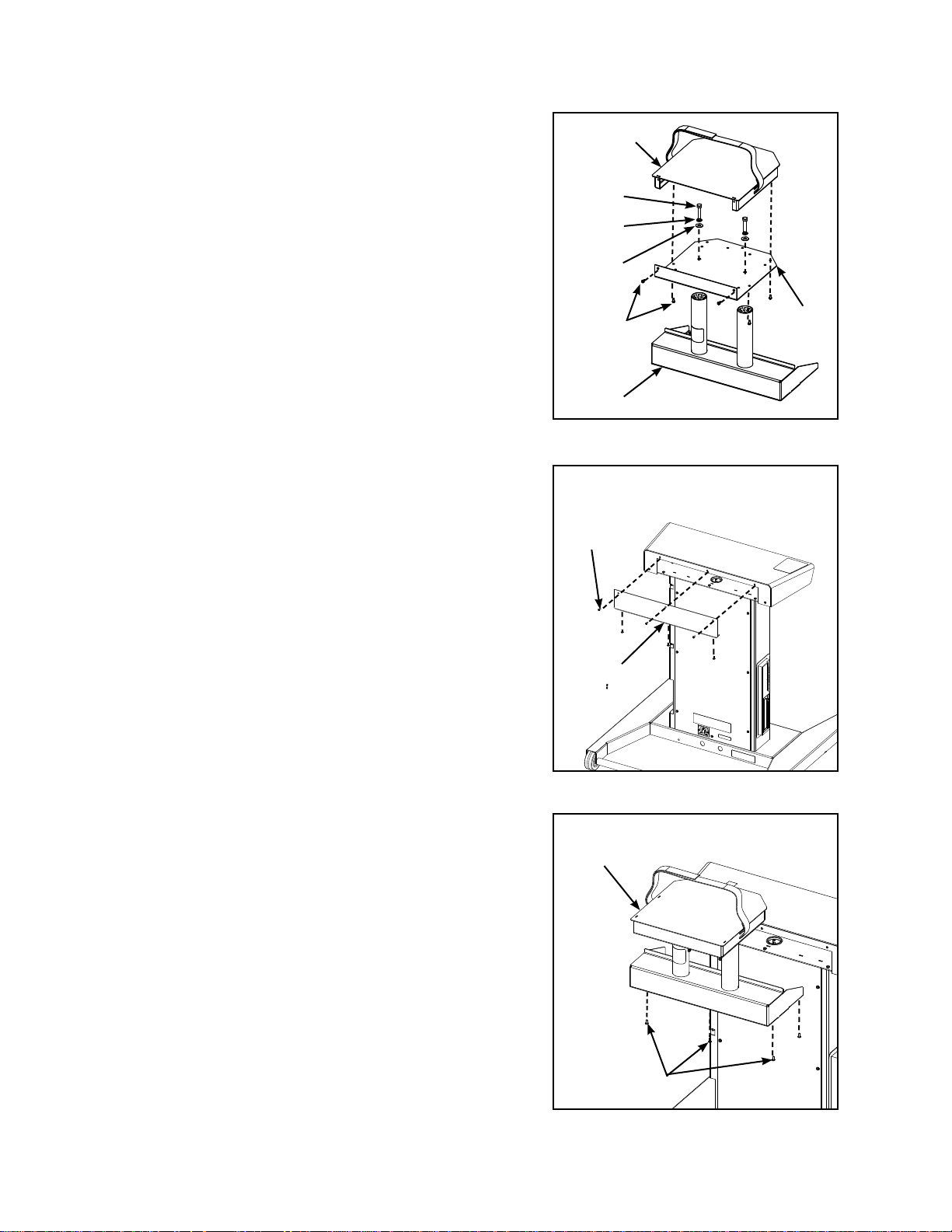
1. Assemble projector shelf.
Top Plate
NOTE: Projector shelf includes top plate, bottom plate and
base.
Locate the projector shelf (#11), six screws (#25), two A.
split lock washers, 5/16” (#29), two fl at washers, 5/16”
(#30) and two bolts, 5/16-18 x 1.50” (#31). See
Figure 1.
Thread the two split lock washers, 5/16” (#29), two B.
fl at washers, 5/16” (#30) and two bolts, 5/16-18 x
1.50” (#31) through the bottom plate into the base
bracket.
Using the adjustable wrench (#27), secure the bottom C.
plate to the base bracket.
Using the Phillips head screwdriver (#28), secure the D.
top plate to the bottom plate with fi ve screws (#25).
2. Attach the projector shelf to cabinet.
Using the Phillips head screwdriver (#28), remove the A.
six screws securing the blank cover to the cabinet.
Set screws aside and discard the blank cover. See
Figure 2.
#31
#29
#30
#25
Base
Figure 1
Screws (6)
Bottom
Plate
NOTE: Do not damage the wires inside the cabinet when
installing the projector shelf.
Place the projector shelf (from step 1) inside the B.
cabinet and align holes. See Figure 3.
Using the Phillips head screwdriver (#28), secure the C.
projector shelf to the cabinet using fi ve of the six
screws removed in step 2A.
Blank
Cover
Figure 2
#11
Screws (5)
Figure 3
Assembly
and Setup
Page 2-11
Page 30

Cybex 760S Owner’s Manual
3. Install projector.
NOTE: Projector, VGA cable and power cable are not
supplied with the unit.
Locate Projector, VGA cable, power cable, wire ties A.
(#32) and wire tie bases (#33).
Place projector on the projector shelf. B. NOTE: Place
projector so lens faces the back of the unit. See
Figure 4.
WARNING: Do not install monitor or television on
projector shelf.
Secure the projector to the shelf by tightly wrapping C.
the straps around the projector. See Figure 4.
Plug the projector’s VGA cable and projector power D.
cable into the projector.
Secure the VGA cable and power cables under the projector shelf using the wire ties (#32) and E.
wire tie bases (#33) provided. See Figure 5. NOTE: Place the wire tie bases in the hole locations
best suited for the projector cables.
Projector (not
included)
Projector lens
Straps
Projector
Shelf
Figure 4
VGA
Cable
Projector
Shelf
#33
Figure 5
4. Remove back panel.
Using a A. Flat head screwdriver , remove the seven screws securing the back panel. See Figure 6.
Remove back panel.B.
5. Install keyboard.
Power
Cable
#32
Back
Panel
Screws (7)
Figure 6
NOTE: Do not cover the warning decal on the left side of the top cover.
Assembly
and Setup
Page 2-12
Locate keyboard (#5).A.
Remove backing from velcro tabs on bottom of keyboard.B.
Page 31

Cybex 760S Owner’s Manual
C. Place keyboard (#5) towards the right side of the top cover of cabinet. Ensure that velcro adheres
to top of cabinet. See Figure 7.
Top
Cover
Warning
Decal
#5
Figure 7
D. Locate the CPU access hole. See Figure 8.
E. Locate the USB plug of the keyboard (#5).
See Figure 9.
F. Insert the USB plug of the keyboard (#5)
through the CPU access hole and into one
of the USB receptacles. See Figure 9.
CPU
Access
Hole
Figure 8
VGA
Receptacle
VGA
Cable
6. Install VGA cable.
Insert the VGA cable into the VGA receptacle A.
in the CPU. See Figure 9.
Secure the VGA cable to the CPU by turning B.
the two screw shafts located on the VGA
cable. See Figure 9.
NOTE: Some projectors may have a USB cable as
part of the VGA cable.
Insert the USB cable (if included) into one of C.
the USB receptacles. See Figure 9.
Verify all cables connecting to CPU are D.
connected properly and securely.
7. Install back panel.
Using a A. Flat head screwdriver, install the seven screws securing the back panel. See Figure 7.
Screw
Shaft
Figure 9
USB
Receptacle
CPU
Access
Hole
USB
Plug
Assembly
and Setup
Page 2-13
Page 32

Cybex 760S Owner’s Manual
8. Install cable access cover.
Locate the cable access cover (#20) and four screws A.
(#25). See Figure 10.
NOTE: Do not pinch the keyboard or VGA cable when
installing the cable access cover.
Guide the keyboard and VGA cable into the channel B.
in the cable access cover (#20). NOTE: The projector
power cable will stay outside the cabinet. See
Figure 10.
Using the Phillips head screwdriver (#28), secure the C.
cable access cover (#20) to the cabinet with four
screws (#25). See Figure 10.
9. Level the unit.
#25
Monitor Power
Keyboard
and VGA
Cables
#20
Cable
Confi rm that the unit is on a level surface. See A.
steps 9B - 9D for leveling.
WARNING: Always use proper lifting methods when
moving heavy items.
Carefully tip the unit back to gain access to the B.
leveling feet.
Locate the leveling feet at the front of the unit. See C.
Figure 11.
Using your hands, adjust the leveling feet up or D.
down until the unit is level.
Using the adjustable wrench (#27) tighten the nut E.
5/16-18 (#20) to secure leveling feet.
10. Connect the power cord.
Plug the power cord into the inlet in the back of the A.
unit. NOTE: Do not plug the power cord into an
outlet at this time. See Figure 12.
11. Visually inspect the unit.
Figure 10
Leveling
Feet
Figure 11
Power
Cord Inlet
Assembly
and Setup
Page 2-14
Carefully examine the unit to ensure that the A.
assembly is correct and complete.
Proceed to B. Testing the Operation section.
Figure 12
Page 33

Cybex 760S Owner’s Manual
Cybex Trazer® Assembly with External monitor
1. Remove back panel.
Using a A. Flat head screwdriver, remove the seven
screws securing the back panel. See Figure 1.
Remove back panel.B.
2. Install keyboard.
Locate keyboard (#5).A.
Remove backing from velcro tabs on bottom of B.
keyboard.
NOTE: Do not cover the warning decal on the left side
of the top cover.
Place keyboard (#5) towards the right side of the C.
top cover of cabinet. Ensure that velcro adheres to top of cabinet. See Figure 2.
Back
Panel
Screws (7)
Figure 1
Warning
Decal
Figure 2
D. Locate the CPU access hole. See Figure 3.
E. Locate the USB plug of the keyboard (#5). See Figure 4.
#5
Top
Cover
Figure 3
CPU
Access
Hole
Assembly
and Setup
Page 2-15
Page 34

Cybex 760S Owner’s Manual
F. Insert the USB plug of the keyboard (#5)
through the CPU access hole and into one
of the USB receptacles. See Figure 4.
3. Install VGA cable.
VGA
Receptacle
Insert the external monitor’s VGA cable into A.
the VGA receptacle in the CPU. See Figure 4.
Secure the VGA cable to the CPU by turning B.
the two screw shafts located on the VGA
cable. See Figure 4.
Verify all cables connecting to CPU are C.
connected properly and securely.
4. Install back panel.
Using a A. Flat head screwdriver, install the
seven screws securing the back panel.
See Figure 1.
5. Install cable access cover.
Locate the cable access cover (#20) and four A.
screws (#25). See Figure 5.
NOTE: Do not pinch the keyboard and VGA cables when
installing the cable access cover.
Guide the keyboard and VGA cables into the channel B.
in the cable access cover (#20). See Figure 5.
Figure 4
VGA
Cable
Screw
Shaft
#25
USB
Receptacle
CPU
Access
Hole
USB
Plug
Keyboard
Cable
Using the Phillips head screwdriver (#28) secure the C.
cable access cover (#20) to the cabinet with four
screws (#25). See Figure 5.
6. Level the unit.
Confi rm that the unit is on a level surface. See A.
steps 6B - 6D for leveling.
WARNING: Always use proper lifting methods when
moving heavy items.
Carefully tip the unit back to gain access to the B.
leveling feet.
#20
VGA
Cable
Figure 5
Assembly
and Setup
Page 2-16
Page 35

Cybex 760S Owner’s Manual
C. Locate the leveling feet at the front of the unit. See
Figure 6.
D. Using your hands, adjust the leveling feet up or
down until the unit is level.
E. Using the adjustable wrench (#27) tighten the
nut 5/16-18 (#20) to secure leveling feet.
7. Connect the power cord.
Plug the power cord into the inlet in the back of the A.
unit. NOTE: Do not plug the power cord into an
outlet at this time. See Figure 7.
8. Visually inspect the unit.
Carefully examine the unit to ensure that the A.
assembly is correct and complete.
Leveling
Feet
Figure 6
Proceed to B. Testing the Operation section.
Power
Cord Inlet
Figure 7
Assembly
and Setup
Page 2-17
Page 36

Cybex 760S Owner’s Manual
WARNING: Be sure that all electrical requirements are met as indicated in the specifi cations at
the front of the manual and at the beginning of this chapter prior to proceeding.
Testing the Operation
Use the following instructions to test the operation of the unit.
NOTE: Read “Using the Beacon” and “Basic Movements” sections before reading the “Detailed
Operations Guide”.
NOTE: Cybex recommends that the unit be unplugged when not in use for extended periods of time.
1. Plug the power cord into a power outlet rated for the following: 115 VAC +5%, 60 Hz and 15 amps.
NOTE: Coil up the remainder of the power cord and place it out of the way.
2. Locate the on/off power switch for your video display. Make sure the power cord is plugged into a
power outlet and turn on as recommended by the manufacturer.
3. Locate the on/off power switch on the left side of the cabinet. Press it once to the on position.
4. The screen will illuminate and after approximately 10 seconds the main screen will be displayed.
5. Adjust the volume by using the F5 (lower) and F6 (increase) keys. Press F10 to turn sound on and
off.
6. Locate beacon and install on the belt using the four metal snaps.
7. Locate the on/off button. Fasten the belt around your
waist with the on/off button located on the right. Adjust
the strap as tight as possible without affecting the user’s
comfort or breathing. See Figure 1.
8. Turn beacon on by pressing the on/off button once.
NOTE: To turn beacon off, Press and hold the on/off
button for three seconds.
NOTE: The beacon will remain on for sixty minutes then turn
off automatically. Press the on/off button at the
beginning of each session so that the beacon will
reset and a new sixty minute time period will begin.
9. Locate the touchpad mounted in the keyboard. Using one fi nger touch the pad and move your fi nger
to guide the pointer on the screen.
10. Log in. NOTE: Each client must LOG IN to have individual performance scores and measurements
saved on the system. See Client Log In.
11. For Cardio Control activities, client must wear a Polar® compatible heart rate monitor.
On/Off Button
Figure 1
Beacon
Belt
12. Select desired category on the left side of video display then press the left key below the touchpad.
13. Select desired activity on the right side of video display then press the left key below the touchpad.
NOTE: Most activities have an options setup screen that allows varying degrees of control or
Assembly
and Setup
Page 2-18
customization of the activity. Default settings for each activity remain until these options are
changed. Changes made for every activity for each individual client are saved in that client’s
personal database.
Page 37

Cybex 760S Owner’s Manual
14. Click OK! in the lower right hand corner of the screen. Stand a few feet away from the front center of
the cabinet. Move in the direction of the on screen commands and towards the center of the bulls eye
target. Remain still during the audible, three second countdown phase while facing the cabinet.
15. After the countdown is complete, move toward your target. Observe that “Physbot” follows your
movements.
16. When fi nished with program, your score screen will appear. Press Enter to continue and return to
setup screen. NOTE: To exit a program early, press the “Esc” (Escape) key to exit program and
return to the main menu.
17. Remove beacon from belt and return it to charging station.
Assembly
and Setup
Page 2-19
Page 38

Cybex 760S Owner’s Manual
Set Date and Time
The date and time need to be synchronized between the PC and the Trazer unit. If the date and time are
not synchronized the database will not be updated correctly. Perform this procedure for any PC’s that
will be running the TrazerMan software and all Trazers in the facility.
Setting the date and time on your PC
1. Using your mouse move your cursor to the lower right of your desktop.
2. Right click the time that is displayed in the lower right corner.
3. From the menu select Adjust Date/Time. See
Figure 1.
4. Click the Time Zone tab.
5. Select your Time Zone from the drop down
menu. Click the Apply button.
6. Click the Date & Time tab.
7. On the left side of the screen select the current
Month, Year and Date. Click the Apply button.
8. On the right side of the screen adjust the clock
to the current time. Click the Apply button.
9. Click the OK button.
Setting the date and time on your Trazer
1. With the Trazer on and in the dormant mode press and hold down the Alt key and then press the Tab
key. Release both keys.
2. Using the touchpad move your cursor to the lower right of your desktop until you see the time
displayed.
3. Using the left button below the touchpad double click the time that is displayed in the lower right
corner.
4. From the menu select Adjust Date/Time. See Figure 1.
5. Click the Time Zone tab.
6. Select your Time Zone from the drop down menu. Click the Apply button.
7. Click the Date & Time tab.
Figure 1
8. On the left side of the screen select the current Month, Year and Date. Click the Apply button.
9. On the right side of the screen adjust the clock to the current time. Click the Apply button.
10. Click the OK button.
Assembly
and Setup
Page 2-20
Page 39

Cybex 760S Owner’s Manual
3 - Operation
Read and understand all instructions and warnings prior to using the unit. See all of the safety-related
information located in Chapter 1.
Intended Use
The intended use of this exercise equipment is to aid or improve general physical fitness and exercise.
For Household or Commercial use. NOTE: Unit shown below contains the optional monitor and bracket.
Operation
Page 3-1
Page 40

Cybex 760S Owner’s Manual
Using the Beacon
WARNING: The Beacon emits invisible, infrared energy in the area of the yellow LED. Do not look
directly at the yellow LED from a distance of less than eighteen inches for extended
periods of time.
1. Remove beacon from charger dock. See Figure 1.
Charger
Dock
Beacon
Charging
LED
On/Off
Switch
Figure 1
2. Securely place beacon onto belt. NOTE: The On/Off switch must be located on the right-hand side
as shown in Figure 2.
On/Off Switch
Figure 2
Operation
Page 3-2
Page 41

Cybex 760S Owner’s Manual
3. Fasten the belt around your waist. Adjust the strap as tight as possible without affecting your comfort
or breathing.
4. Verify the on/off button for the beacon is located on your right. See Figure 3.
External Charger Port
On/Off Button
Figure 3
5. Make sure that the beacon points toward the video screen at all times. Keep hips square to the
unit, facing the video screen. NOTE: Turning your waist so that the beacon no longer points at the
screen will cause loss of tracking.
6. Keep the signal path from the beacon to the unit clear. For example, wearing a baggy shirt that
covers the beacon will cause loss of signal. Placing your hand in front of the beacon will also cause
loss of signal.
NOTE: Tracking is restored when condition is corrected.
7. When finished, remove beacon from belt and snap belt
onto belt mounts on right side of cabinet. See Figure 4.
8. Place beacon in the charger dock with the On/Off
switch on the right side. See Figure 1. NOTE: It is very
important that the beacon be placed in the charger dock
correctly. It takes about 12 hours to obtain a full charge.
A fully charged beacon should provide about ten hours
of use.
NOTE: The beacon will charge only when the unit is plugged
in and turned on. The charging LED will remain on
when charging. The charging LED will blink if there is
any problem with charging the battery.
Yellow LED
Belt Mounts
NOTE: The beacon can be charged externally using
the power adapter supplied with the unit. See the
Recharging Battery Beacon section in Chapter 4.
Figure 4
Operation
Page 3-3
Page 42

Cybex 760S Owner’s Manual
Basic Movements
WARNING: Review safety information in Chapter 1 before using the unit.
NOTE: Make all movements with your knees slightly bent and hips square to the unit.
NOTE: Make all movements within the user area.
NOTE: Make all movements to contact target (disc, ball, ring, etc.).
NOTE: Maintain balance and control at all times.
Left or Right - Use a sideways shuffling motion to move left or right.
Forward or Backward - Use quick steps to move forward or backwards.
Diagonal - Use quick steps to move diagonally.
Jump - Bend at the knees and jump upward.
Squat - Bend at the knees to squat.
Lunge - Step towards target while bending knees then return to starting position.
Operation Guide
NOTE: Read “Using the Beacon” and “Basic Movements” sections before reading the “Operation Guide”.
NOTE: Cybex recommends that the unit be unplugged when not in use for extended periods of time.
1. Plug the power cord into a power outlet rated for the following: 115 VAC +5%, 60 Hz and 15 amps.
NOTE: Coil up the remainder of the power cord and place it out of the way.
2. Locate the on/off power switch for your video display. Make sure the power cord is plugged into a
power outlet and turn on as recommended by the manufacturer.
3. Locate the on/off power switch on the left side of the cabinet. Press it once to the on position. The
green light on the power switch will indicate the power is on.
4. The screen will illuminate and after approximately 10 seconds the main screen will be displayed.
5. Locate beacon and install on the belt using the four metal snaps.
6. Fasten the belt around your waist with the on/off button located on the right. Adjust the strap as
tight as possible without affecting the user’s comfort or breathing.
7. Turn beacon on by pressing the on/off button once. NOTE: To turn beacon off, press and hold the
on/off button for three seconds.
NOTE: The beacon will remain on for sixty minutes then turn off automatically.
8. Locate the touchpad mounted in the keyboard. Using one finger, touch the pad and move your
9. Log in. NOTE: Each client must LOG IN to have to have individual performance scores and
Operation
Page 3-4
finger to guide the pointer on the screen.
measurements saved on the system. See Administration and Reports.
Page 43

Cybex 760S Owner’s Manual
10. For Cardio Control activities, client must wear a Polar® compatible heart rate monitor.
11. Select desired category on the left side of video display then press the left key below the touchpad.
12. Select desired activity on the right side of video display then press the left key below the touchpad.
NOTE: Most activities have an options setup screen that allows varying degrees of control or
customization of the activity. Default settings for each activity remain until these options are
changed. Changes made for every activity for each individual client are saved in that client’s
personal database.
13. Select Show Testing Performance & Analysis. NOTE: To get a Performance Analysis Report (PAR)
for any specific activity, you must select Show reports & Save data. This will also save the data
from this specific activity in the client’s database. Basic data such as game scores are saved for
all activities performed. The reports function is always on automatically for activities in the Testing
section.
14. Click OK! in the lower right hand corner of the screen. Stand a few feet away from the front center
®
of the Trazer
cabinet. Move in the direction of the on-screen commands and toward the center of
the bulls eye target. Remain still during the audible, three-second countdown phase while facing the
Trazer® cabinet.
15. After the countdown is complete, move toward your target. Observe that “Physbot” follows your
movements.
16. When finished with program, your score screen will appear. Press Enter to continue and return to
setup screen. NOTE: To exit a program early and return to the main menu, press the “Esc” (Escape)
key twice.
17. Remove beacon from the belt and return it to charging station. The charging station is located at the
front of the cabinet. Place beacon with front side facing the cabinet. See Figure 1.
18. If the Trazer unit is not in use for extended periods of time, turn off and unplug from the wall.
NOTE: To turn the unit off, press and hold the power button for six seconds (or until the green powerlight
turns off).
Operation
Page 3-5
Page 44

Cybex 760S Owner’s Manual
Trazer Activities
The following screens and accompanying text describe the activities that are available to Trazer clients
who are registered by an authorized Administrator. Users must LOG IN to access a screen for any
Trazer activity.
NOTE: All screens have extensive HELP information that can be accessed by clicking HELP on the
bottom of the screen. Help can also be accessed by pressing the F1 key.
Main Menu
The Trazer Main Menu screen contains icons that guide the user to select a desired activity from seven
activity categories. Each activity category has a number of associated screens that allows selection of
specific exercise routines, games, drills, reports, or parameter settings.
The seven Trazer activity categories are listed below and appear as icons on the screen. See Figure 5.
• Testing
• Performance T raining Drills
• Performance T raining Games
• Cardio Control Games
• Personal Training
• Rehabilitation
• Administration & Reports
Figure 5
The row of buttons on the bottom of the Main Menu provides the following selections.
Operation
Page 3-6
LOG ON• - Logs a current client or administrator into the system
LOG OUT• - Logs a current client or administrator out of the system
HELP• - Provides HELP information for the current screen selection
INTRO• - Provides a description of the Trazer system including setup, basic operation, reports,
activities, definitions and other information
NEXT• - Selects the next screen in a sequence
Page 45

Cybex 760S Owner’s Manual
Testing
The Testing screen provides access to a group of standardized activities designed to challenge and
assess specific movement skills and functional performance. Trazer accurately measures reaction time,
acceleration, deceleration, speed, power, jump height and body CG control in simulations of real-world
functional demands and sports activities. In addition to the standard activity tests, custom-designed
activities can be set up to create tests specific to the training goals of a particular individual or group.
See Figure 6.
The activity selections accessible from the
Testing screen are shown below. Each
selection has an associated screen for
establishing specific testing parameters. A
Performance Analysis Report (PAR) can
be selected to appear at the completion
of each test. Click HELP for additional
information regarding setup for standard or
custom-designed activities.
Figure 6
Reaction - The Reaction activity tests very short hip-shifting, toe raise, and squat movements
emphasizing reaction time and quick response. This selection allows setting a specific number of
repetitions to collect Reaction data. A repetition is a complete cycle of all directional movements, not just
a movement in one direction. Measurements are Reaction Time, Average Power and Total Time.
Mini-T - The Mini-T activity tests forward and backward movement speed, right-left dynamic reaction,
and direction change quickness and movement speed. This selection allows setting a specific number of
repetitions to collect Mini T Reaction data. A repetition is a complete cycle of all directional movements,
not just a movement in one direction. Measurements are Reaction Time (forward only), Acceleration,
Deceleration, Speed, Average CG Height, Total Time, Total Distance and Heart Rate.
Lateral Speed - The Lateral Speed activity tests right-versus-left movement speed, with emphasis on
acceleration, deceleration and directional change ability. This selection allows setting a specific number
of repetitions to collect Lateral Speed data. A repetition is a complete cycle of all directional movements,
not just a movement in one direction. Measurements are Acceleration, Deceleration, Average Power,
Average CG Height, Total Time, Total Distance and Heart Rate.
Jump Fatigue - The Jump Fatigue activity test maximal muscle power and power endurance over a
series of repeated maximal jumps. This selection allows setting duration times to collect Jump Fatigue
data. Measurements are Maximum and Average Jump Height, Average CG Height, Average Power,
Total Distance and Heart Rate.
Operation
Page 3-7
Page 46

Cybex 760S Owner’s Manual
Performance Training Drills
The Performance Training Drills screen provides access to a group of standardized drills designed to
provide extensive variations and combinations of challenges to reaction time, agility and coordination,
quickness, dynamic balance, flexibility, muscular strength and power, cardiovascular endurance, and
sport-specific responses and movements. See Figure 7.
Figure 7
One or more of the following selections are available for each drill.
Direction• - Selects direction of movement (left, right, forward, backward, up and down
movements)
Duration• - Sets total time for activity
Volume• - Sets number of repetitions in a drill (complete cycles), number of sets and rest between
sets
Sequence• - Selects Group (all reps run one direction at a time), Sequential (all directions run in
repeated cycle) or Random (all reps for all directions intermixed)
Movement Scale• - Sets distance in inches for left/right, forward/backward, up and down
movements
CG Contro• l - Enforces a specific stance during the activity to provide feedback for optimal results
Pause• - Sets duration of pause between successive movement cues (a pause is required to get
reaction time measurements)
The activity selections accessible from the Performance Training Drills screen are shown below. Each
selection has an associated screen for establishing specific drill parameters. A Performance Analysis
Report (PAR) can be selected to appear at the completion of each test rather than a scorecard.
Default settings can be restored at any time. Click HELP for additional information regarding setup or
performance measurement.
Shift & Bump - The Shift & Bump activity allows creation of low-amplitude activities suitable for
rehabilitation applications, and activities for seniors and younger children. Activities can be set up for
specialized forward, backward, lateral, vertical and rotary balance and stability challenges. Bilateral
and single-leg stance leans, hip shifts, rotary movements, squats and toe raises can be combined for
progressive functional challenges.
Operation
Page 3-8
Page 47

Cybex 760S Owner’s Manual
Lunge - The Lunge activity cues single-step movements with knee and hip bending in selected
directions. Goal of activity can be either quick reaction and powerful movement, or smooth, controlled
movement. Movement scale distances in Lunge should be adjusted to individual leg lengths, strength
and flexibility, or for specific functional or sports movement requirements. Activity level can be adjusted
to accommodate all levels from seniors to athletes,
Jump - The Jump activity delivers a series of cues for sub maximal or maximal vertical and/or lateral
jumps. Jumps can be counter-movement jumps (drop quickly and jump up) or squat jumps from a fixed
CG height. This drill is an excellent conditioner for skiing and snowboarding; motocross, enduro and
trials riding; skateboarding and other extreme roller sports.
React - The React activity delivers a series of cues for reaction movements in up to eight directions from
a center base position. Each movement requires multiple steps depending on client’s size, power and
flexibility. The React drill is an excellent training activity for any sport that requires covering a specific
space or zone with quick reaction to the ball or an opponent.
Get Back - The Get Back activity cues a series of movements in forward and forward-diagonal
directions with the requirement to return to the rear baseline position as quickly as possible after
each movement. This activity is a great all-around reaction training, quickness training, and general
conditioning activity.
Shuttle - The Shuttle activity can be set up to create a lateral speed drill, a forward-backward speed
drill, or a clockwise and counterclockwise box drill. Shuttle activities stress foot-movement pattern skills
for speed, body CG control, and quick deceleration/acceleration for direction change.
Cutting - The Cutting activity delivers a series of reaction take offs to hit randomized targets that create
a sequence of diagonal movements followed by the quickest possible return to a rear-field base position.
Cutting is sport-specific to football and basketball, but it is also a great general conditioning activity that
adds functional challenge and fun to any fitness program.
Jump & Recover - The Jump & Recover cues a series of left and/or right lateral movements followed
by vertical jumps with an additional special cue designed to train proper landing technique to amortize
landing forces. A proper jump recovery technique is extremely important for injury prevention,
particularly those relating to ACL injuries and achilles tendon injuries.
Bounding - The Bounding activity cues a series of left and right lateral jumps. It is a plyometric strength
and power building activity, so proper technique to amortize landing forces and minimize ground
time should be instructed and encouraged. Bounding provides excellent conditioning for all sports
emphasizing leg strength, power and endurance. NOTE: Plyometrics is a type of exercise training
intended to produce fast, powerful movements, and improve the functions of the nervous system.
Operation
Page 3-9
Page 48

Cybex 760S Owner’s Manual
Performance Training Games
The Performance Training Games screen provides access to a group of games that provide a mix of
fun, competition, fitness challenge and serious physical training. The games are designed to test and
improve reaction time, quickness, speed, agility, power, endurance, and sport-specific responses and
movements. They are used extensively for sports performance training and rehabilitation. In addition
to physical demands, games challenge visual perception, interpretation, movement decision making,
strategy, cognitive processing, simulation of response to environmental and sports situations, and
associated balance and stability requirements. See Figure 8.
Figure 8
One or more of the following selections are available for each game.
Duration• - Sets time period for play (play can also be limited by “faults” rather than by time only)
Fault Setting• - Sets number of faults to end the game (setting depends on game played - Trap
Door Falls, Ball Explosions, Spike Contact, or Opponent Goals)
Level• - Sets level for starting difficulty of play
Fixed or Progressive • - Fixed (stay at beginning level) or Progressive (raises level based on
score achieved)
CG Control• - Sets CG target height, if desired, for coaching and training optimal stance for
quickness, speed, power and stability
The activity selections accessible from the Performance Training Games screen are shown below. Each
selection has an associated screen for establishing specific game parameters. Default settings can be
restored at any time. Click HELP for additional information regarding setup or game play.
Trap Attack - The Trap Attack game challenges visual perception, interpretation, movement decision
making and agility. Progressing to higher levels can achieve significant cardiovascular training benefits.
Trap Attack is an excellent Trazer orientation activity, and a good warm-up for testing for a series of
more demanding drills and games.
Jump Explosion - The Jump Explosion game is an extremely demanding game best played for shorter
durations of 90 seconds or less. It is suitable for players from age 6 to well conditioned 60 year-olds.
The game is simple in presentation, but considerable strategy is required to achieve high game points.
Operation
Page 3-10
Page 49

Cybex 760S Owner’s Manual
Spike Dodge - The Spike Dodge game provides a demanding visual perception challenge. It is
intriguing and fun for many tennis, racquetball and volleyball players, but it can be frustratingly difficult
for others. Time and practice dramatically improve performance since this game requires constant
movement as balls come faster and red spikes proliferate at higher levels.
Goalie Wars - The Goalie Wars game is a fun and challenging fitness activity for any age and an
excellent way to introduce children to the concepts of offensive and defensive play. Goalie Wars
emphasizes quick direction change and movement strategy. As progressive difficulty increases, the
goalie will adapt to the client’s playing style, anticipate the client’s offensive moves and play a more
aggressive offensive game.
Cardio Control Games
The Cardio Control Games screen provides access to a fun mix of fitness challenges and serious
physical training in games that automatically keep the client’s heart rate in a specified training range.
Trazer monitors the heart rate and increases the difficulty level as required until the client is in the range
specified in the setup screen or activity design. When the heart rate exceeds the specified limit, Trazer
will either temporarily stop the activity or reduce the difficulty level until the heart rate recovers to within
the specified range. See Figure 9.
Figure 9
One or more of the following selections are available for each game.
Duration• - Sets time period for play
Level• - Sets level for starting difficulty of play
Target Heart Rate• - Automatically sets desired heart rate range based on age and sex (except
for the Custom Cyclic setting). For Custom Cyclic, the desired heat rate can be set to the client’s
lowest and highest heart rates to simulate a favorite sport or activity.
The activity selections accessible from the Cardio Control Games screen are shown below. Each
selection has an associated screen for establishing specific game parameters. The user must wear a
Polar-compatible heart rate monitor for all games. Default settings can be restored at any time. Click
HELP for additional information regarding setup or game play.
Operation
Page 3-11
Page 50

Cybex 760S Owner’s Manual
Cardio Trap Attack - The Cardio Trap Attack game is similar to the Performance Training Trap Attack
game except the level of the Cardio game is controlled by the heart-rate monitor rather than by a preset
level or a performance-based level.
Cardio Jump Explosion - The Cardio Jump Explosion game is similar to the Performance Training
Jump Explosion game except the level of the Cardio game is controlled by the heart-rate monitor rather
than by a preset level or a performance-based level.
Cardio Spike Dodge - The Cardio Spike Dodge game is similar to the Performance Training Spike
Dodge game except the level of the Cardio game is controlled by the heart-rate monitor rather than by a
preset level or a performance-based level.
Cardio Goalie Wars - The Cardio Goalie Wars game is similar to the Performance Training Goalie
Wars game except the level of the Cardio game is controlled by the heart-rate monitor rather than by a
preset level or a performance-based level.
Personal Training
Trazer is a professional tool for personal trainers offering fully customizable, computerized and
automated performance testing and training programs. The Personal Training screen provides access
to a number of expert-designed programs. Personal training activities greatly extend customization and
automation capabilities by allowing trainers to create extended sequences of drills and games matched
to an individual client’s needs, goals and capabilities. See Figure 10.
The activity selections accessible from
the Personal Training screen are shown
below. These activities are Scripted
Activity Protocols (SAPs) - an extended
sequence of selected Performance
Training Drills and/or Games that run
automatically under computer control.
Each SAP is designed for specific
training goals and individual capability
levels.
Names of the SAPs may or may not
be self-explanatory. If in doubt, facility
trainers should be consulted before
starting an activity. A Performance
Analysis Report (PAR) can be selected
to appear at the completion of each
activity. Click HELP for additional
information regarding setup or
Figure 10
Sports Readiness for Kids - The SAPs in this activity are designed to prepare kids from 6 to 16 for
general athletic participation.
Sports Readiness for 50+ - The SAPs in this activity are designed to prepare older individuals to start
or return to general athletic participation.
performance measurement.
Balance/Stability - The SAPs in this activity are designed to challenge and train balance and stability,
focusing primarily on lower demand activities especially suitable for senior fitness programs. Some
advanced activities that require significant strength and motor control are also included.
Operation
Page 3-12
Page 51

Cybex 760S Owner’s Manual
Reaction/Agility/Quickness - The SAPs in this activity are designed to challenge and train reaction
time, movement decision making, quick acceleration and direction change capabilities.
Strength & Power - The SAPs in this activity are designed to build strength and power using added
resistance provided by appropriately selected and placed floor-tethered resistance bands. It is important
to understand that resistance bands apply downward force as well as resistance to movement in one
direction and acceleration force in the other.
CVP Programs - The SAPs in this activity are designed to provide general cardiovascular-pulmonary
conditioning. The Trazer system will monitor the client’s heart rate and automatically increase the
difficulty level until the client is in the range specified in the design of the SAP activity. When heart rate
exceeds the specified limit, Trazer will either temporarily stop the activity or reduce the difficulty level
until the heart rate recovers to within the specified range.
Sport Specific - The SAPs in this activity are designed to create challenges and training demands that
simulate key performance elements of specific sports. Before starting these activities, clients should be
able to complete the highest level activities in the applicable Sports Readiness section (Kids or 50+)
without over-exertion.
Facility Custom - The SAPs in this activity have been designed by this facility’s expert trainers. SAPs
in this section may be available for all facility clients, or may be accessible only by certain groups (for
example a local sports team), or only to the clients of individual trainers.
Client Custom - The SAPs in this activity have been designed by the facility’s expert trainers to create
customized programs for individual clients. NOTE: These SAPs are visible and accessible only to the
clients for whom they were created. Client must LOG IN to access his or her custom program.
Rehabilitation
Trazer is a professional tool for rehabilitation specialists offering fully customizable, computerized and
automated rehabilitation protocols, and performance testing and training programs. The Rehabilitation
screen provides access to a number of expert-designed programs. Rehabilitation activities greatly
extend customization and automation capabilities by allowing clinicians to create extended sequences of
Performance Training Drills and Games matched to individual client’s needs, goals and capabilities. See
Figure 11.
Figure 11
Operation
Page 3-13
Page 52

Cybex 760S Owner’s Manual
The activity selections accessible from the Rehabilitation screen are shown below. These activities
are Scripted Activity Protocols (SAPs) - an extended sequence of selected Performance Training Drills
and/or Games that run automatically under computer control. Each SAP is designed for specific training
goals and individual capability levels.
Names of the SAPs may or may not be self-explanatory. If in doubt, facility trainers should be consulted
before starting an activity. A Performance Analysis Report (PAR) can be selected to appear at the
completion of each activity. Click HELP for definitions of rehabilitation terminology and for additional
information regarding setup or performance measurement.
Ankle - The SAPs preloaded in this activity are designed for ankle rehabilitation. Progression from
Phase 1 through Phase 6 is designed to start at the earliest allowable weight-bearing intervention and
advance to a level suitable for full return to sports participation.
Knee - The SAPs preloaded in this activity are designed for knee rehabilitation. Progression from Phase
1 through Phase 6 is designed to start at the earliest allowable weight-bearing intervention and advance
to a level suitable for full return to sports participation.
Hip - The SAPs preloaded in this activity are designed for hip rehabilitation. Progression from Phase 1
through Phase 6 is designed to start at the earliest allowable weight-bearing intervention and advance to
a level suitable for full return to sports participation.
Balance/Stability - The SAPs preloaded in this activity are designed for balance and stability training
and rehabilitation. Progression from Phase 1 through Phase 6 is designed to start at the earliest
allowable weight-bearing intervention and advance to a level suitable for full return to normal activities.
CVP Programs - The SAPs preloaded in this activity are designed for Cardiovascular-Pulmonary (CVP)
rehabilitation. Progression from Phase 1 through Phase 6 is designed to start at early intervention,
as soon as the work levels associated with unsupported full-weight-bearing activities are allowable.
Progression through SAPs above phase 4 includes demanding aerobic activities with brief intervals of
maximal performance.
Facility Custom - The SAPs in this activity have been created by the facility’s trainers to meet the
special needs of their patient population.
Client Custom - The SAPs in this activity have been created by the facility’s trainers to meet the special
needs of specific patients.
Operation
Page 3-14
Page 53

Cybex 760S Owner’s Manual
Administration & Report
Both Administrators and registered Clients can access the Administration & Reports category.
NOTE: For detailed descriptions of the available functions, single-click on the buttons to the right on the
screen, and then click HELP. To perform a function or application, double-click on the button
or click NEXT when it is selected. Detailed instructions for each operation are in the associated
HELP screens.
Client Functions
Clients have access to two Administration functions when Administration & Reports is selected in the
Main Menu. See Figure 12.
Figure 12
Reports - View Score Cards and Performance Analysis Reports from previously performed activities,
and create Progress Reports.
Synchronize - Copy up-to-date files to a USB datastick or update files on this Trazer unit with data from
another unit. Clients can view and transfer their own personal files, but cannot delete or alter any data.
Operation
Page 3-15
Page 54

Cybex 760S Owner’s Manual
Administrator Functions
Administrators have access to seven Administration functions when logged in as an Administrator. See
Figure 13.
Figure 13
SAP Editor - Create Scripted Activity Protocols (sequences of selected Performance Training Drills and/
or Games that run automatically under computer control).
Client Management - Add and Edit Client records and access each client’s activity database to view
and print reports.
Admin Setup - Add, Edit and Delete Administrator accounts.
Admin Synchronize - Use a USB datastick to combine all settings, records, data and created SAPs
among multiple Trazer units and/or PCs that have the optional Trazer PC Admin program installed. This
function allows all systems associated with a facility to share the most up-to-date information, testing
activities and training programs.
Client Synchronize - Import and export individual client records and associated data.
Trazer Setup - Enter facility identification data on the Trazer unit and customize options and settings
for the needs and preferences of the facility and its client population. Access system serial number,
software revision information, and contact information for customer service and tech support.
On-Site Calibration - Requires the optional Calibration Hardware Kit. This function calibrates the
system’s tracking optoelectronics software to correct for environmental interference in the installed
location.
Operation
Page 3-16
Page 55

Cybex 760S Owner’s Manual
Log In
Admin Log In
For initial administrator LOG IN, User Name “admin” and Password “trazer” (case sensitive) may be
entered. The entries can then be changed to a secret Admin Name and Password, if desired, for
functions and information that should be restricted to facility personnel.
1. Locate the touchpad mounted in the keyboard. Using one finger, touch the pad and move your
finger to guide the pointer on the screen.
2. From the Main Menu, select Administration & Reports .
3. On the right side of the screen, select Admin Login .
4. Provide requested information.
Client Log In
Each client must LOG IN to have individual performance scores and measurements saved on the
system. Before logging in, each client must be registered by an authorized Administrator.
NOTE: If no one else in the facility is registered with the same fi rst or last name, just the full fi rst or last
name and password are required for LOG IN. If there are multiple clients with the same name, the
system may require more information (fi rst name, last name, middle initial, birth date).
1. Locate the touchpad mounted in the keyboard. Using one finger, touch the pad and move your
finger to guide the pointer on the screen.
2. On the bottom left of the Main Menu, click LOG IN.
3. Provide requested information.
Operation
Page 3-17
Page 56

Cybex 760S Owner’s Manual
Client Management
The Client Management function provides administrative access to all Client Records and the associated Client
Activity Database.
Administrators can Add a new client, Edit the record of an existing client, or Delete a client (not recommended
unless there were major errors in creating the original record).
This function also provides access to the Reports application, which allows viewing the complete activity history
of a selected client. Individual activities can then be selected by type, date and time to review Score Cards and
Performance Analysis Reports, or to create Progress Reports.
Client Management functions can also be performed on a PC that has the optional Trazer PC Admin program
installed. This will allow printing of reports to any attached printer. See Figure 14.
Figure 14
Operation
Page 3-18
Page 57

Cybex 760S Owner’s Manual
Add Client
1. Log in as administrator.
2. From the Main Menu, select Client Management to access the Client Database Management
screen.
3. On the Client Database Management screen, click Add Client to access the Client Record
Information screen. See Figure 15.
On the Client Record Information screen,
Enter client’s First name, Middle initial and
Last name. Click the TAB key to enter the
next field. NOTE: Client name cannot be
changed once saved. Enter name carefully
and double-check spelling before saving.
NOTE: Keep a separate record of client
names and PIN’s exactly as
entered on system. Use Trazer
Client Log form (shown at the end
of this chapter) to record name and
PIN exactly as entered on system.
Refer to the TrazerMan Software
Manual if you are managing the
database and reports from a PC.
Figure 15
4. Enter the clients Birth Month, Day and Year. Use two digits for Day and Month, use four digits for
Year, Example: 01 09 1968. NOTE: The Maximum Heart Rate value will be incorrect if the birth date
is entered incorrectly.
5. Enter Weight, Height and Leg Length (Leg Length is measured from floor to center of hip). NOTE:
When entering Weight, Height and Leg length, use English units (Pounds and Inches).
6. Enter Resting Heart Rate and Pin/Password.
7. Select Gender.
8. Click OK and client will be entered in system. NOTE: Member ID will be generated by the software.
Edit Client
1. Log in as administrator.
2. From the Main Menu, select Client Management to access the Client Database Management
screen.
3. Highlight the client whose record is to be revised.
4. Click Edit Client.
5. Revise the client record, as required.
6. Click OK and the client record will be entered in system.
Operation
Page 3-19
Page 58

Cybex 760S Owner’s Manual
Delete Client
1. Log in as Administrator.
2. From the Main Menu, select Client Management to access the Client Database Management
screen.
3. Highlight the client whose record is to be deleted.
4. Click Delete.
5. Click OK and the client record will be deleted from the system.
Reports
Clients have access to this feature if a facility Administrator has created a client record and the client is
logged in. The client record includes basic identification and physical information about the client that the
system needs to maintain client files; calculate appropriate training heart rate ranges based on age and
sex; and calculate calorie burn for activities based on bodyweight.
Associated with the client record is a
database of the client’s personal activity
settings, scores and measurements that
are automatically saved for every activity
performed while logged in. This information
can be viewed on the View Reports screen.
See Figure 16.
NOTE: Reports are available only for
existing clients that have performed
at least one activity.
Figure 16
Client reports can be accessed from the View Reports screen.
1. Log in as administrator or client.
NOTE: Administrators proceed to step 2; Clients proceed to step 4
2. From the Main Menu, select Client Management to access the Client Database Management
screen.
3. Highlight the client whose record is to be accessed.
4. Click Reports to access the View Reports screen.
Operation
Page 3-20
Page 59

Cybex 760S Owner’s Manual
The View Reports screen lists all the activities performed to date by the selected client identified at
upper right of screen.
Select an activity - From the left column list, select an activity by clicking on its name. Only activities
that have been performed by the selected client will be displayed.
Select report type - Click the Score Card check box and then the Performance Analysis check box
to see all the dates and times that data for either or both of these reports has been collected (middle
column).
Select a performance - From the middle column, select a particular date and time on which the
selected activity was performed. To view the report associated with this performance of the activity, click
OK.
Score Card
A Score Card is automatically displayed at the end of all Performance Training Games. The Score
Card is also automatically displayed for all Drill and Testing activities when “Show Testing Performance
Analysis” is selected on the activity screen. In this case, the more detailed Performance Analysis Report
will be displayed after the activity is completed. See Performance Analysis Report section. NOTE: Data
cannot be saved unless a client logs in before starting an activity.
Score Card data can be accessed when logged in as an administrator or by using the TrazerMan PC
program, which allows you to transfer the Trazer database and administrative functions to a PC. This
allows you to create a Progress Report for Score Card data saved from previously performed activities.
To view a Score Card for an activity selected in the left column of the View Reports screen, select a
date/time from the middle column, and click OK. See Figure 17.
To print the Score Card, click Print. To return
to reports page, click Back. NOTE:Trazers do
not usually have printers directly connected.
Printing is usually done from a PC, after
transferring the data via a USB stick.
If you want to vew the report in Metric units,
click the Metric box in the lower right-hand
corner of the screen.
Figure 17
Operation
Page 3-21
Page 60

Cybex 760S Owner’s Manual
Performance Analysis
The Performance Analysis Report is automatically displayed at the end of all Drill and Testing activities
when “Show Testing Performance Analysis” is selected on the activity screen. Only the Score Card will
be displayed if “Show Testing Performance Analysis” is not selected on the activity screen for a drill.
NOTE: Data cannot be saved unless a client logs in before starting an activity.
Performance Analysis data can be accessed when logged in as an administrator, or by using the
TrazerMan PC program, which allows you to transfer the Trazer database and administrative functions
to a PC. This allows you to create a Progress Report for Score Card data saved from previously
performed activities.
To view the Performance Analysis for an activity selected in the left column of the View Reports screen,
select a date/time from the middle column, and click OK. To print the Performance Analysis, click Print.
To return to reports page, click Back. See Figure 18.
If you want to vew the report
in Metric units, click the Metric
box in the upper right-hand
Performance Analysis Screen
corner of the screen.
Performance Analysis Printout
Figure 18
Progress Report
After selecting an activity by its name in the left column of the View Reports screen, click the Create
Progress Report check box. Both the middle and right columns will display identical lists of all the dates
and times that data for this activity have been collected. To see comparable selections, toggle back and
forth between the Score Card and Performance Analysis check boxes.
Select one performance each in the middle and right column to be compared. Click OK to create
and view the Progress Report. NOTE: Do not select the same date and time in the second and third
columns. The progress report needs to look at data from different sessions.
Operation
Page 3-22
Page 61

Progress Report Screen
Cybex 760S Owner’s Manual
To print the Progress Report,
click Print. To return to reports
page, click Back. See Figure
19.
Progress Report Printout
Figure 19
SAP Editor
The Scripted Activity Editor screen is
used to create sequences of selected
Performance Training Drills and/or
Games that run automatically under
computer control. A SAP can be created
for a sport-specific training program or
rehab protocol, for a specific client’s or
patient’s individual program, or for a
particular group (e.g., a test or training
program for all members of a Little
League Baseball team).
Figure 20
SAPs can be configured for training
only or for a specialized performance
test. When a SAP is used for testing,
all of the like types and directions of
movement in the entire sequence are
combined for the purposes of data
calculation. See Figure 20.
Operation
Page 3-23
Page 62

Cybex 760S Owner’s Manual
Delete a Scripted Activity
To delete an SAP, log in as Administrator and select SAP Editor to access the Scripted Activity Editor
screen. Then proceed as follows.
1. Click Delete.
2. Click OK and the client record will be deleted from the system.
Create a New Scripted Activity
To create a new scripted activity, log in as Administrator and select SAP Editor to access the Scripted
Activity Editor screen. Then click the buttons identified below in the sequence indicated and perform the
associated activity.
1. NEW - “New Scripted Activity” will appear in green at the bottom of the left column, which means
this activity is selected for editing.
2. RENAME - Type in an appropriate name for the SAP. Keep name length under 30 total spaces.
The RENAME button is now the SET button. Click to assign the new name which will now appear in
alphabetical order in the left column.
3. INSERT - This allows selecting available activities from the Performance Training Games and Drills
categories. Selecting an activity will insert it in the right column of the Editor screen.
4. REMOVE - This allows removal of a specific unwanted activity in the right column.
5. EDIT SETTINGS - This brings up the setup screen for an activity selected in the right column.
Change the options on this screen as appropriate for the new SAP. Be sure to set a Rest Period
between activities. To save the settings, click OK. Repeat this process for each activity.
6. EDIT DESCRIPTION - This creates the activity description and performance instructions that appear
onscreen at the start of the SAP and during rest periods between activities. Click on an activity
name in the right column. Click Edit Description to bring up the text entry screen. Type the activity
description followed by a colon, and then type the desired performance instructions in 40 words or
less.
7. UP-DOWN ARROWS - This allows changing the order of activities. Select one activity at a time and
move it up or down in the sequence list using the Up-Down Arrows.
8. EDIT CATEGORIES - This allows assigning the SAP to an appropriate activity category (e.g.,
Personal Training - Sport Specific; Rehabilitation - Client Custom). With the SAP name selected in
the left column, click Edit Categories to bring up the Category Assignment screen. Instructions are in
the associated HELP screen.
9. USER ACCESS - This brings up the User Access screen for the selected SAP to allow setting
access privileges. The left list box contains the users without access, and the right list box contains
the users with access. Access may be given or revoked by selecting users and moving them
between the list boxes. All users without access may be provided access by pressing ADD ALL.
Similarly, everybody may be denied access by pressing CLEAR. Additionally, access can be
provided to all users by simply checking the Available to all users box. Click DONE to return to
the SAP editor. NOTE: When the “Available to all users” button is lit, selective User Access is not
necessary, and the appropriate functions are disabled. This button must be off in order to select and
move user names between list boxes. See Figure 21.
Operation
Page 3-24
Page 63

Figure 21
Cybex 760S Owner’s Manual
10. DELETE - This allows deleting an entire SAP by selecting a name in the left column and clicking
DELETE.
11. DONE - This allows saving all the SAPs that have been created one after another in the Editor.
Click DONE to save all work performed.
Use an Existing SAP to Create a New SAP
To create a new SAP from an existing SAP, log in as Administrator and select SAP Editor to access the
Scripted Activity Editor screen. Then proceed as follows.
1. Click DUPLICATE and select an existing SAP from the left column that most closely matches the
criteria and objectives for the new SAP. When an SAP is selected, its component activities appear in
the right column for review.
2. Review the current settings for each activity and modify the selected SAP as required. Follow the
same instructions for each operation as followed when creating a new SAP. Provide a new SAP
name, remove unwanted activities and insert desired new activities.
3. Complete the new SAP. Edit the settings, descriptions and categories for each included activity as
appropriate, and then assign desired user access.
4. Click DONE to save all the SAPs created.
Operation
Page 3-25
Page 64

Cybex 760S Owner’s Manual
Admin Setup
The Admin Setup function allows an existing Administrator to Add an additional administrator account,
or to Edit or Delete an already existing account using the Admin Management screen. The list box at left
shows all the current administrator accounts. See Figure 22.
Figure 22
The default administrator account that is initially created at the factory has the username “admin” and
the password “trazer”. It is recommended that this account name be changed as soon as an authorized
facility administrator is chosen for the system.
NOTE: Until the factory default account name has been changed, a
warning will appear each time the Trazer is started.
You may add other administrators if you like, each with their own
name and password. Facilities with multiple Trazers might wish to
have a different administrator and password for each individual
Trazer, plus a master Administrator that has access to all Trazers.
To edit or delete an administrator account, proceed as follows.
NOTE: Administrator accounts are specifi c to individual Trazer units so that facility owners may control
use, if desired.
1. Click on the username and then click Edit or Delete. Clicking Edit will bring up the Administrator
Account Information screen where username or password associated with the administrator’s real
name can be changed. Clicking Delete will delete the selected administrator’s account.
2. Click OK to save a change.
3. Click BACK to continue.
4. If all administrators are deleted, you will not be able to log in as Administrator until the Trazer is
Operation
Page 3-26
turned off, and re-started. When Trazer is started, it looks for an Administrator. If none is found, a
defalut is created with the name admin and the password trazer.
Page 65

Cybex 760S Owner’s Manual
Synchronize
Synchronization allows client records on a USB datastick to be synchronized with the records on a
Trazer. The Trazer has three Synchronization functions:
Client Synchronization •
Administrator Synchronization •
Administrator-Client Synchronization•
Before a datastick can be used for synchronization, the datastick must be initialized for Trazer data.
Datastick Initialization - A datastick with client data for import will have already been initialized. If an
initialized datastick is not available, insert a regular datastick into the Trazer or PC USB port. Wait a
few seconds for the USB drive to be recognized by the system. On the Trazer, the datastick will be
automatically identified. On a PC, it will be necessary to identify and select the correct drive location.
After the datastick is recognized, click INITIALIZE DATASTICK.
NOTE: Initializing will delete any Trazer data that may already exist on the datastick.
Client Synchronization
This function allows a client to download records and associated performance data from the client’s
Trazer unit onto a USB datastick. This data can then be transferred to other Trazer units to create an
up-to-date client record on that Trazer. Synchronization is performed via the Client Synchronize screen.
Clients have access to this feature if a facility Administrator has created a client record. See Figure 23.
Figure 23
Client Synchronization is accomplished as follows.
1. Log in as client.
2. Insert an initialized datastick.
3. From the Main Menu, select Synchronize to access the Client Synchronize screen.
4. Click OK.
Operation
Page 3-27
Page 66

Cybex 760S Owner’s Manual
Synchronization may take anywhere between a couple of seconds to several minutes, depending
upon the amount of data to be transferred and the speed of the USB stick. When a “Synchronized
Successfully!” message is displayed, the process is completed. If you get an error message, you may
need to re-initialize your datastick.
Administrator Synchronization
Synchronization is performed via the Administrator Synchronize screen. This function allows any Trazer
to be synchronized with a USB datastick. It combines the latest information from both the datastick and
the Trazer or PC to create updated records and files in both memory locations. This datastick can then
be used to synchronize other Trazer units and/or PCs so that all units associated with a facility share the
latest client records, activity databases, activity settings and SAPs. See Figure 24.
NOTE: This function will not copy optional software installed on one system (or any of the associated
data) to another system that does not have this optional software.
Figure 24
Administrator Synchronization is accomplished as follows.
1. Log in as administrator.
2. Insert an initialized datastick.
3. From the Main Menu, select Admin Synchronize to access the Administrator Synchronize screen.
4. Click OK.
Synchronization may take anywhere between a couple of seconds to several minutes, depending
upon the amount of data to be transferred and the speed of the USB stick. When a “Synchronized
Successfully!” message is displayed, the process is completed. If you get an error message, you may
need to re-initialize your datastick.
Operation
Page 3-28
Page 67

Cybex 760S Owner’s Manual
Administrator Client Synchronization
This function allows an Administrator to synchronize the client record and activity database for a single
client between a Trazer unit and a USB datastick. Its primary use is to import and export individual client
records and associated data. Using this function, a client’s files from a Trazer at another facility can be
added to a unit at this location, or a client’s files from this location can be put on a datastick for a client
who plans to use a Trazer at another facility.
There are two list boxes on the Administrator Client Synchronize screen. When the datastick is correctly
recognized by the Trazer or PC, all clients on the inserted data stick will appear on the left and all clients
on the Trazer or PC will appear on the right. Click radial buttons to sort by first name, last name, or
client ID. See Figure 25.
Figure 25
Administrator Client Synchronization is accomplished as follows
1. Log in as administrator.
2. Insert an initialized datastick.
3. From the Main Menu, select Client Synchronize to access the Administrator Client Synchronize
screen.
4. Select desired client on either list.
NOTE: It is usually helpful to display only unique clients on either source (check box for “Show Unique
Clients Only). This will eliminate redundant listing of clients that are already on both the datastick
and the Trazer or PC.
5. Click OK.
Synchronization may take anywhere between a couple of seconds to several minutes, depending
upon the amount of data to be transferred and the speed of the USB stick. When a “Synchronized
Successfully!” message is displayed, the process is completed. If you get an error message, you may
need to re-initialize your datastick.
The synchronization operation can be repeated for multiple clients by inserting datasticks and clicking
Refresh USB Contents.
Operation
Page 3-29
Page 68

Cybex 760S Owner’s Manual
Trazer Setup
Trazer Setup accesses the Trazer Setup, Options & Service screen, which allows an Administrator
to enter facility identification information to be printed on reports (e.g., to send to a coach, parent, or
referring physician). It also sets a number of options to customize the Trazer system to the needs and
preferences of the facility and its client population.
In addition, this screen provides the system serial number, software revision information, and contact
information for customer service and tech support. See Figure 26.
Figure 26
Trazer Setup is accomplished as follows.
1. Log in as administrator.
2. From the Main Menu, select Trazer Setup to access the Trazer Setup, Options & Service screen.
3. Proceed as follows to complete the setup.
Facility information/Trazer Location - Upper and lower case data entry is preferred.
Trazer Settings - these settings customize this Trazer to the needs and preferences of the facility and
its client population.
Allow Anonymous Users • - Allows users to play games and perform Drills and SAPs without
logging in. Testing or Cardio Control activities and activity data cannot be accessed or saved.
Lock All Settings• - Allows only an administrator to change activity settings. Trazer settings will
not be changed during a synchronization operation.
Play Music During Activities• - Allows Trazer sound effects volume to be regulated using the F5
and F6 keys. Uncheck this box for no music.
Hardware Noise Filter• - Enabling or disabling the noise filter is a technical decision. This filter
recognizes and minimizes any environmental interference that might affect data accuracy. This
function applies very tight constraints to data collection that are beyond what is required for
typical installations, but research facilities and some medical facilities will find it beneficial.
Operation
Page 3-30
Page 69

Cybex 760S Owner’s Manual
Speed Meter • - This check box sets whether or not the vertical visual feedback bar appears on the
left of the screen in many activities. This bar shows real-time changes in movement speed. The
slider sets the scale of the bar. Default peak setting is 25 ft/sec.
Posture Meter • - This check box sets whether or not the vertical visual feedback bar appears
on the right of the screen in many activities. This bar shows real-time changes in CG height,
including jumps, from the calibrated full-standing height, which is assigned a “0” value on the
bar. Default Low and High settings are -20 inches and + 20 inches.
Trazer Info • - The information listed here may be required for tech support and other customer
service needs. Contact Cybex Customer Service number as described in Chapter 6. Requests
for non-emergency technical support and information should be directed to Cybex by email.
On-Site Calibration
This function calibrates the system’s tracking optoelectronics software to correct for environmental
interference in the installed location and is essential for accurate measurements. In some installation
environments, calibration may be required to optimize activity in Performance Training Games and Drills.
If testing is to be performed, the system must be calibrated when installed. If the area surrounding an
installed system is significantly changed (e.g., a mirror is added to a near-by wall), recalibration will be
required to ensure accuracy.
There must be no object or person other than the test subject in the Trazer field area during activity.
This area is from the front face of the Trazer extending 3 feet to either side and 9 feet back. Clients
should be observed from behind or to the side of the field.
The Trazer activity and performance measurement field is a 6-foot, three-dimensional space (1.83-meter
cube). The forward edge of this area is located exactly 3 feet from the front face of the Trazer unit.
The three measurement dimensions are “X” (left-right), “Y” (up-down) and “Z” (forward-backward). The
calibration procedure requires that X and Z calibration points are accurately marked out in a 6-foot
(1.83m) square on the floor in front of the Trazer. Self-adhesive dots are provided for this purpose.
There are 9 required floor calibration
points, as indicated on the Calibration
screen. The centerline of the field is marked
perpendicular and centered relative to
the Trazer optics at 3 feet (.91m), 6 feet
(1.83m) and 9 feet (2.74m). The sidelines
of the field are marked at these same
distances at points perpendicular to and 3
feet (.91m) on either side of the centerline
marks. See Figure 27.
Figure 27
Operation
Page 3-31
Page 70

Cybex 760S Owner’s Manual
After the floor is marked, attach the Trazer Beacon to the provided adjustable stand making sure that
the power button is on the right.
Trazer Setup is initiated as follows.
1. Log in as administrator.
2. From the Main Menu, select On-Site Calibration to access the Calibration screen.
3. The calibration program has onscreen instructions that guide the entire procedure.
Basically, the Beacon is sequentially placed at each calibration point to match an onscreen grid, and this
point is marked by hitting Enter on the keyboard or by using an air mouse to click for the Next Step.
To place the Beacon accurately, put the front foot of the stand on the calibration point with the Beacon
face square to the Trazer unit. No object or person should be anywhere in the Trazer field area between
the Trazer and the Beacon. Mark the Trazer Beacon position. If using the keyboard to mark the location,
stand to one side and behind the front of the unit.
When the Beacon is properly positioned, the message on the right side of the screen must read
“TRACKING.” If the message reads “ERROR,” press the power button on the Beacon. Make sure that
the Beacon is fully charged before starting the calibration procedure. If the “ERROR” message continues
to appear, reboot the Trazer and try again. If problem persists, call Cybex Customer Service. See Figure
28.
Figure 28
NOTE: Before starting the calibration
procedure, check to see if the Trazer
can see the beacon in all four corners
of the field area. When you see that
the calibration program is TRACKING,
move the beacon to each corner. If
the Trazer can not track the beacon
in each of these four corners, you will
not be able to properly calibrate the
unit.
Operation
Page 3-32
Page 71

Cybex 760S Owner’s Manual
Terms Used
This section lists some of the common terms used in this chapter. To access additional terms
and other Trazer information, click INFO on the bottom of the Main screen or HELP on a selected
activity.
Average CG Height - Overall Average CG Height (exclusive of jumping movements) for each
movement vector is shown as + or - from calibrated height.
Average Power - This value is power in watts averaged over the entire activity set taking
bodyweight into account.
Best & Average Jump Height - Reported as overall values for complete activity.
CG - Center of gravity. Proper location of the beacon positions the client’s approximate CG.
CG Height - Real time CG height is shown on the feedback bar during activities. CG is shown as +
or - from calibrated height when standing straight as required at start of each activity. This data and
the CG height control function that is available on setup screens can be used to identify and train
optimal CG height for power speed and stability.
L/R MV Deficit % - (Left/Right Movement Vector Deficit Percent) These values are the comparisons
of each major measurement to determine performance differences between movements to the left
and right. Calculation assumes the better side is 100% and shows the percentage deficit with the
direction of deficit indicated by an arrow. If the arrow points left, movements to the left were lower in
overall performance by the indicated percentage.
Max/Avg. Heart Rate - Reported for overall activity set.
Movement - This can begin after selecting the OK! icon on the screen. Upon entering a program
the user will be instructed to move to the center of the field.
Power - In watts per kg of bodyweight. Multiply by bodyweight for your power in watts (1 kg = 2.2
lbs). In a sports block, check, or collision more power keeps moving, less power is moved aside.
Note that it is important to associate correct body weight at time of test with this measurement.
Weight of clients on weight loss or weight gain programs should be checked approximately every
30 days and updated by using the “Edit Client” function. Bodyweight in kg at time of test is shown in
parentheses next to Overall Average Watts value in bottom row of Performance Analysis Report.
Reaction Time - Thousandths of seconds from instant target cue appears until acceleration in
correct direction occurs. This measures how quickly an individual perceives, interprets and develops
muscle forces required to respond to objects, obstacles and sports situations.
Reports - Reports for all programs can be selected from the Administration & Reports page.
Scoring - Upon completion of a program the user score will be posted. This information will be
stored if the user has logged in. One point times difficulty level for each disc or ball contact, or goal.
Minus one point times difficulty level for each game specific “fault”.
Speed - Average feet or meters per second over all movements in each specified vector (right,
left, forward, back, up, down). Rapid acceleration and deceleration while controlling body center of
gravity are the keys to achieving higher speeds while reacting, cutting and dodging.
Total Calories - Reported for overall activity set.
Total Distance - This is reported as an overall value for the entire activity set.
Total Time - Total time from start to end of activity set.
% Rank - This indicates percentile rank of individual client in the specific activity as compared to
everyone else who has performed the same activity on the same unit.
Operation
Page 3-33
Page 72

Symbols Used
Cybex 760S Owner’s Manual
Physbot - Animated character that represents your location on the screen.
Help - When Help is selected information will be available for that particular
screen.
Log In - Logs in a current client.
Log Out - Logs a client out of the system.
Back - Goes back to the previous screen when selected.
key performs the same function.
OK - Activates the current selection.
double-click performs the same function.
Next - Goes to the next screen when selected.
Scroll Bar Arrows - Scroll up or down through the current list.
In most places, the Enter key or
In most places, the Esc
Operation
Page 3-34
Page 73

Targets
Cybex 760S Owner’s Manual
Targets include (not limited to):
Black Center Ring - Move to this calibration (starting) position and stand
straight at full height for 3-2-1 countdown.
Blue Diamond - Lunge, take a step toward target while bending at the knees,
then return to starting position.
Orange Bumper - React and move quickly to “bump” the orange bumper.
Red Disc - React and move quickly to “step” on the red disc.
Red Spike - Avoid red spikes by moving away from them.
Trap Door - Avoid trap door by jumping over or stepping around.
White Ball - Contact white balls by moving in front of or under them as they
come towards you. To contact white balls resting on the ground use a lunging
motion towards them.
Yellow Ball - Heel raise or jump to strike yellow ball.
Yellow Ring - Position yourself over target and bend at the knees to squat
above yellow ring.
Operation
Page 3-35
Page 74

On Screen Feedback
Score - During a program, the user score will be posted. This information
will be stored if the user has logged in. One point times difficulty level is
awarded for each disc or ball contact, or goal. One point times difficulty level
is subtracted for each game-specific “fault”.
Time - Displays time remaining.
Level - Displays intensity level selected in setup screen.
Calories - Displays total calories burned.
Cybex 760S Owner’s Manual
Speed Meter - The speed of each movement is displayed as feet per
second. The meter is located in the lower left corner of screen.
CG Height and Range Meter - High and low body center of gravity during
each movement direction. Practice getting lower to find your optimal CG
height for power, speed and stability. The meter is located in the lower right
corner of screen.
Operation
Page 3-36
Page 75

*
Member ID
Cybex 760S Owner’s Manual
Client Log
®
Trazer
PIN Gender Trainer / Clinician
CLIENT NAME Date of Birth Physical Info (check/update BW every 30 days)
LAST FIRST M.I. M / F MO DAY YEAR BW HT LL Rest HR Max HR Last Name
Enter last three digits only of Member ID assigned by system when client record is saved
*
Operation
Page 3-37
Page 76

Cybex 760S Owner’s Manual
Operation
Page 3-38
SCORE CARD
Point Score
Facility Rank
Level Achieved
Total Distance
Total Time
Calories Burned
Average CG Height
Jump Height Max/Avg.
Heart Rate Max/Avg.
Page 77

Cybex 760S Owner’s Manual
Operation
Page 3-39
Page 78

Cybex 760S Owner’s Manual
This page intentionally left blank.
Operation
Page 3-40
Page 79
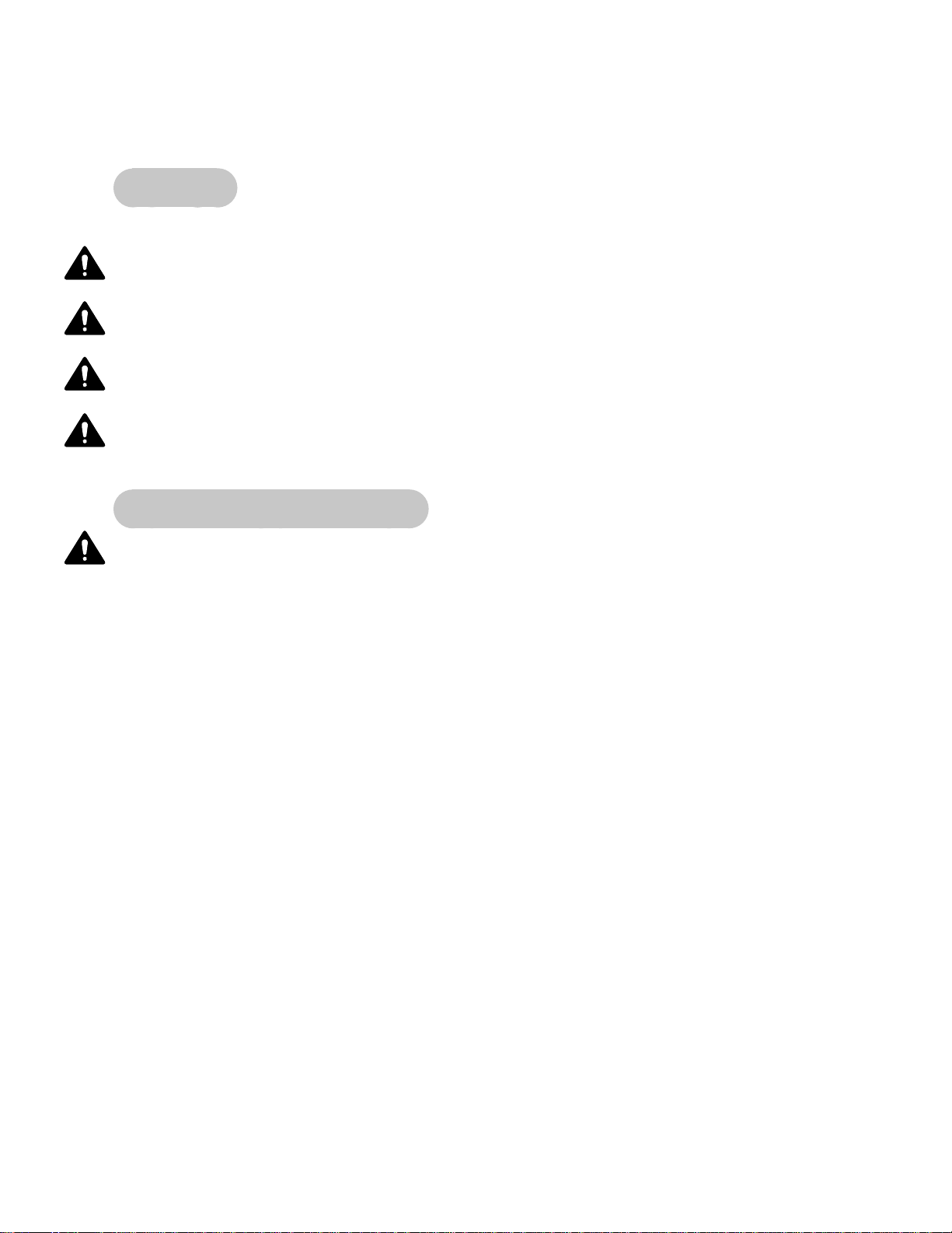
Cybex 760S Owner’s Manual
4 - Preventive Maintenance
Warnings
All warnings listed in this chapter are as follows:
WARNING: All maintenance activities shall be performed by qualified personnel. Failure to do so
could result in serious injury.
WARNING: To prevent electrical shock, be sure that the unit is unplugged from the electrical
outlet before performing any cleaning or maintenance procedures.
WARNING: DO NOT open battery, dispose of in fire, put in backwards, mix with other battery
types or short circuit. Battery may ignite, explode, leak or get hot causing injury.
WARNING: Use only NiMH batteries. Use of any other kind of battery may cause it to leak,
rupture or explode, resulting in personal injury and property damage.
Regular Maintenance Activities
WARNING: All maintenance activities shall be performed by qualified personnel. Failure to do so
could result in serious injury.
Preventive maintenance activities must be performed to maintain normal operation of your unit.
Keeping a log of all maintenance actions will assist you in staying current with all preventive
maintenance activities.
NOTE: Worn or damaged components shall be replaced immediately or the unit removed from service
until the repair is made.
NOTE: Cybex is not responsible for performing regular inspection and maintenance actions for your
unit. Instruct all personnel in equipment inspection and maintenance actions and also in
accident reporting/recording.
NOTE: DO NOT open CPU cover, Warranty is void if label is tampered with, No user serviceable parts
inside.
Preventive
Maintenance
Page 4-1
Page 80

Cybex 760S Owner’s Manual
Cleaning Your Trazer
WARNING: To prevent electrical shock, be sure that the unit is unplugged from the electrical
outlet before performing any cleaning or maintenance procedures.
The optical tracker, beacon, cabinet and video monitor require minimal cleaning when used in the
manner prescribed in this guide. It is recommended to keep these free from dust accumulation by
occasionally wiping with a slightly damp, cotton cloth. Although the beacon is designed to prevent
moisture from entering the case, do not use an excessively wet cloth or immerse in water. Avoid using
paper towels, which may scratch the plastic lens. Avoid using harsh chemical cleaners on the cabinet.
Follow the manufacturer’s recommendations for cleaning the video monitor.
NOTE: Do not spray cleaning solution directly on the unit. Direct spraying could cause damage to the
electronics and will void the warranty.
NOTE: Do not apply pressure on the Optical Tracker Lenses during cleaning.
Recharging Beacon Battery
The beacon is powered from a rechargeable NiMH battery, similar to those used in cell phones.
Typically, you can expect approximately 10 hours of operation from a fully charged battery.
It is highly recommended that a regular recharging schedule be followed. The beacon should be
recharged overnight by simply placing the beacon into the recharging dock. Observe correct
orientation so the metal contacts on the front side of the beacon align with the pins protruding from the
charger dock. If properly positioned, the beacon’s green status light (charging LED) glows solid during
charging. Once fully charged, the green light turns off.
When charging the beacon, follow the instructions listed in step #8 under Using the Beacon, located in
Chapter 3. The beacon can also be charged externally using the power adapter supplied with the unit.
NOTE: Use Cybex supplied adapter only, Wall mount NEMA plug 90-240VAC 50/60Hz (TR-19025) or
Desk top unit IEC-320, 90-240VAC 50/60Hz (TR-19060, requires additional country specific
IEC-320 power cord).
Beacon LED Status
1. Locate the LED on the back of the beacon. See
Figure 1.
2. Refer to the chart below.
LED is on = beacon is charging
LED is off = battery in beacon is 90+% charged
LED is blinking = battery in beacon is very low
and needs to be charged
(1) AA NiMH Rechargeable Battery
Preventive
Maintenance
Page 4-2
Figure 1 (decal on back of beacon)
Page 81

Cybex 760S Owner’s Manual
Replacing Beacon Battery
DANGER: DO NOT open battery, dispose of in fire, put in backwards, mix with other battery
types or short circuit. Battery may ignite, explode, leak or get hot causing injury.
Replace battery with AA NiMH battery only. DO NOT use Alkaline, Carbon Zinc, Lithium Ion, Nickel
Cadmium (NiCd) or any other kind of battery.
DANGER: Use only NiMH batteries. Use of any other kind of battery may cause it to leak,
rupture or explode, resulting in personal injury and property damage.
Dispose of used batteries appropriately.
Remove the battery if storing the unit for periods in excess of six months. The battery is located in the
beacon.
1. Using a Phillips head screwdriver
remove the four Phillips head screws
from the back cover. See Figure 2.
2. Remove the rubber o-ring from the
battery mounts.
3. Remove the battery.
4. Install new battery with the correct
orientation. The positive (+) end of the
battery faces down. See Figure 3.
5. Install rubber o-ring by hooking onto
one battery mount. Make one half twist
and hook onto other battery mount.
See Figure 3.
6. Install back cover with four screws
removed in step 1.
Phillips
Head
Screws
Figure 2
Battery
Battery
Mounts
Rubber
O-ring
Figure 3
+
Positive
(+) End Of
Battery
Preventive
Maintenance
Page 4-3
Page 82

Cybex 760S Owner’s Manual
Disposing of CPU Battery
WARNING: Dispose of the CPU battery according to the instructions.
The CPU contains a lithium battery and is not accessible by the user. Dispose of the unit or CPU
appropriately.
Environment
Reflective Surfaces - Do not place unit in areas with reflective surfaces that will interfere with
operation. Reflective surfaces can cause loss of tracking, jittery Physbot or a significant variation
between actual and expected beacon operation.
Static Electricity - Depending upon where you live, you may experience dry air, causing a common
experience of static electricity. This may be especially true during the winter season. You may notice
a static build-up just by walking across a carpet and then touching a metal object. The same can hold
true while working out on your unit. You may experience a shock due to the build-up of static electricity
on your body and the discharge path of the unit. If you experience this type of situation, you may want
to increase the humidity to a comfortable level through the use of a humidifier.
Humidity - The unit is designed to function normally in an environment with a relative humidity range
of 30% to 75%.
NOTE: Do not install or use the unit in an area of high humidity, such as in the vicinity of a steam room,
sauna, indoor pool or outdoors. Exposure to extensive water vapor, chlorine and/or bromine
could adversely affect the electronics as well as other parts of the machine.
Temperature - The unit is designed to function normally in an environment with an ambient
temperature range of 50o F (10o C) to 104o F (40o C) degrees.
Storage
Humidity - The unit can be shipped and stored in an environment with a relative humidity range of
10% to 90%.
NOTE: Do not store the unit in an area of high humidity, such as in the vicinity of a steam room, sauna,
indoor pool or outdoors. Exposure to extensive water vapor, chlorine and/or bromine could
adversely affect the electronics as well as other parts of the machine.
Temperature - The unit can be shipped and stored in an environment with an ambient temperature
range of 32o F (0o C) and 140o F (60o C) degrees.
Batteries - If storing the unit for periods in excess of six months, remove the batteries. See
Rechargeable Batteries section for location of batteries.
Preventive
Maintenance
Page 4-4
Page 83

5 - Customer Service
Contacting Service
Hours of phone service are Monday through Friday from 8:30 a.m. to 6:00 p.m. Eastern Standard Time.
For Cybex customers living in the USA, contact Cybex Customer Service at 888-462-9239.
For Cybex customers living outside the USA, contact Cybex Customer Service at 508-533-4300 or fax
508-533-5183.
Find information on the web at www.cybexinternational.com or by e-mail at techhelp@cybexintl.com.
Serial Number
Your serial number can be found on the back of the unit. See Figure 1.
For your convenience record your serial number below so that you will have it ready if you call Cybex
Customer Service.
Serial Number
Figure 1
Serial
Number
Location
Customer
Service
Page 5-1
Page 84

Return Material Authorization (RMA)
The Return Material Authorization (RMA) system outlines the procedures to follow when returning
material for replacement, repair or credit. The system assures that returned materials are properly
handled and analyzed. Follow the following procedures carefully.
Contact your authorized Cybex dealer on all warranty-related matters. Your local Cybex dealer will
request an RMA from Cybex, if applicable. Under no circumstances will defective parts or equipment be
accepted by Cybex without proper RMA and an Automated Return Service (ARS) label.
1. Call the Customer Service hotline listed on Page 5-1 for the return of any item that is defective.
2. Provide the technician with a detailed description of the problem you are having or the defect in the
item you wish to return.
3. Provide the model and serial number. The serial number is located on the back of the unit as shown
in Figure 1. The serial number begins with a letter, for example: R09-101331100.
4. At Cybex’s discretion, the technician may request that you return the problem part(s) to Cybex for
evaluation and repair or replacement. The technician will assign you an RMA number and will send
you an ARS label. The ARS label and RMA number must be clearly displayed on the outside of the
package that contains the item(s) to be returned. Include a description of the problem, the serial
number of the unit and the name and address of the owner in the package along with the part(s).
5. Forward the package through UPS to Cybex.
Attn: Customer Service Department
(place your RMA# here) RMA# XXXXXXX
Cybex International, Inc.
10 Trotter Drive
Medway, MA 02053
NOTE: Merchandise returned without an RMA number on the outside of the package or shipments sent
C.O.D. will not be accepted by the Cybex receiving department.
Customer
Service
Page 5-2
Page 85

Damaged Parts
Materials damaged in shipment should not be returned for credit. Shipping damages are the
responsibility of the carrier (UPS, Federal Express, trucking companies, etc.).
Apparent Damage - Upon receipt of your shipment, check all boxes carefully. Any damage seen with
a visual check must be noted on the freight bill and signed by the carrier’s agent. Failure to do so will
result in the carrier’s refusal to honor your damage claim. The carrier will provide you with the required
forms for filing such claims.
Concealed Damage - Damage not seen with a visual check upon receipt of a shipment but noticed later
must be reported to the carrier as soon as possible. Upon discovery of the damage, a written or phone
request to the carrier asking them to perform an inspection of the materials must be made
within ten days of the date of delivery. Keep all shipping containers and packing materials: they will be
needed as part of the inspection process. The carrier will provide you with an inspection report and the
necessary forms for filing a concealed damage claim. Concealed damage is the carrier’s responsibility.
Ordering Parts
Fax your order to 508-533-5183. To speak with a customer service representative, call 888-462-9239
(for customers living within the USA) or 508-533-4300 (for customers outside the USA).
CAUTION
Use only Cybex replacement
parts when servicing.
Failure to do so could result
in personal injury.
Cybex will void warranty if
non-Cybex replacement parts
are used.
Customer
Service
Page 5-3
Page 86

This page intentionally left blank
Customer
Service
Page 5-4
Page 87

Cybex 760S Owner’s Manual
Appendix A - Technical Specifications
Specifications
Width: 29” (74 cm).
Depth: 31” (79 cm).
Height: Cabinet 34.5” (86.25 cm), Cabinet with monitor bracket 63” (160 cm) approx.
Weight of Product: Base unit, 80 lbs. (36.5 kg).
Monitor or projector shelf unit, 90 lbs. (41 kg).
Shipping Weight: Base unit, 91 lbs. (42 kg).
Monitor or projector shelf unit, 101 lbs. (46 kg).
Console Features: Keyboard with built in Touchpad.
Heart Rate Features: Built-in wireless Polar® heart rate receiver (transmitter belt not included).
Frame Colors: Black chrome.
Connectivity: Two USB ports.
Power Requirements: 115 VAC +5%, 60 Hz, 1.6 amps and 1-Phase.
230 VAC +5%, 50 Hz, 1.6 amps and 1-Phase.
Beacon
Power Requirements: One 1.2 V, 1800 mAH, NiMH battery (included).
Beacon Charger Power
Requirements: 90-240 VAC, 600 mA for desktop IEC-320 unit.
90-240 VAC, 200 mA for wall type unit.
Other: USB Memory Stick, Beacon, Small Waist Belt, Large Waist Belt,
built-in Beacon charging station and external beacon charger.
Monitor, Projector: Not included.
Options: Monitor bracket or Projector shelf.
34.5”
(86.25 cm)
29” (74 cm)
Shown with optional monitor configuration
63”
(160 cm)
31” (79 cm)
Technical
Specifications
Page A-1
Page 88

Cybex 760S Owner’s Manual
This page intentionally left blank
Technical
Specifications
Page A-2
Page 89

Page 90

10 Trotter Drive Medway, MA 02053 • 508-533-4300 • FAX 508-533-5183
www.cybexinternational.com • techhelp@cybexintl.com • techpubs@cybexintl.com
 Loading...