

Page 1

XP4000 Series
Installer/User Guide
4991 Corporate Drive
Huntsville, Alabama 35805-6201 • USA
256-430-4000 (Fax) 256-430-4030
www.cybex.com
Page 2
INSTRUCTIONS: The exclamation point within an equilateral triangle is
intended to alert the user to the presence of important operating and maintenance
(servicing) instructions in the literature accompanying the appliance.
DANGEROUS VOLTAGE: The lightning flash with arrowhead symbol,
within an equilateral triangle, is intended to alert the user to the presence of
uninsulated “dangerous voltage” within the product's enclosure that may be of
sufficient magnitude to constitute a risk of electric shock to persons.
PROTECTIVE GROUNDING TERMINAL: A terminal which must be
connected to earth ground prior to making any other connections to the
equipment.
POWER ON: This symbol indicates the principle on/off switch is in the on
position.
POWER OFF: This symbol indicates the principle on/off switch is in the off
position.
Page 3

Table of Contents
Chapter 1: Product Overviews
XP4000 Series Overview .......................................................... 1
XP4010/XP4040/XP4080 Units................................................. 1
Operation Modules .................................................................... 4
Cables ....................................................................................... 5
XP4000 Series Complements ................................................... 5
Features and Benefits ............................................................... 5
Limitations & Restrictions .......................................................... 7
Safety Precautions .................................................................... 8
Chapter 2:
Installing User Interface Modules
Connecting the Local Console Peripherals
(Front Access Model Only) ...................................................... 9
Secondary Console Modules .................................................... 10
Installing the Secondary Console Modules (XPDU and XPLU) 10
Connecting the User Interface Cables (XPDU and XPLU) ....... 11
Using Non-multisync Monitors .................................................. 15
Chapter 3:
Attaching Computers to an XP4000 Series Unit
Attaching a PC Computer ......................................................... 17
Attaching an IBM RS/6000 Workstation .................................... 24
Attaching a Silicon Graphics Workstation ................................. 25
Attaching a Macintosh Computer .............................................. 26
Attaching a Sun Workstation ..................................................... 30
Attaching a Hewlett-Packard Workstation ................................. 34
Page 4

Chapter 4: Attaching Terminals
Overview ................................................................................... 39
Installing the XPIQ and XPSI Modules...................................... 40
Attaching Terminals to the XPSI Module ................................... 40
Addressing Terminals on the XPSI Module ............................... 41
Getting Started .......................................................................... 41
On-Screen Menu Overview ....................................................... 43
Using System Management Tools ............................................. 46
Using the Security Monitor ........................................................ 49
Chapter 5: Installing Expansion Units
Overview ................................................................................... 51
Expansion Capabilities .............................................................. 51
Installation ................................................................................. 52
XP4000 Unit Placement ............................................................ 52
Computer/User Console Distribution......................................... 54
Transmitter/Receiver Board Configuration ................................ 56
Transmitter/Receiver Board and Expansion Cable Installation . 59
Chapter 6: XP4400
XP4400 Overview ..................................................................... 61
Features and Benefits ............................................................... 63
Installation ................................................................................. 63
LED Operation .......................................................................... 66
LCD Display Operation ............................................................. 67
FLASH Upgrading ..................................................................... 70
Sample Configurations .............................................................. 71
Page 5

Chapter 7: Basic Operations
LEDs and Front Access Display ................................................ 75
Multiplatform Keyboard Translation ........................................... 77
Keyboard Control ...................................................................... 79
Keyboard Switching .................................................................. 80
Multiuser Operation ................................................................... 81
Multimedia Operation ................................................................ 85
Serial Peripherals ...................................................................... 85
KeyScan .................................................................................... 86
Broadcast Mode ........................................................................ 87
Follow Mode .............................................................................. 88
Swap Mode ............................................................................... 88
Privacy Mode ............................................................................ 88
Command Forwarding............................................................... 89
Chapter 8:
XPDU Module and On-Screen Display
Overview ................................................................................... 91
On-Screen Menu Overview ....................................................... 92
The Channel List Menu (User Level Access) ............................ 92
The User List Menu ................................................................... 93
User Controls Menu (User Level Access) ................................. 94
The Command Line Entry Menu ............................................... 95
Administrator Functions ............................................................ 96
Administrator Controls............................................................... 99
Dual Monitor Support ................................................................ 102
Chapter 9: Advanced Operations
System Control and Maintenance ............................................. 105
Serial Port Advanced Operations
(for XPLU, XPDU and LCI modules) .................................... 106
Serial Port Advanced Operations (for XPRB Modules) ............. 108
Multi-Part FLASH Upgrades...................................................... 111
Keyboard Switching with Different Cybex Products .................. 112
Physical and Virtual Switches of Computer Interface Modules ......... 113
Page 6

Chapter 10: Applications
Star/Daisy Chain Combination Configuration............................ 115
Recommended Configurations.................................................. 116
Chapter 11
Complement Products and Optional Modules
XPRB Module............................................................................ 123
The ReBoot xP .......................................................................... 126
Chapter 12:
Product Assistance and Troubleshooting
Customer/Technical Support ..................................................... 127
Troubleshooting......................................................................... 127
Chapter 13: Appendices
Appendix A ................................................................................ 131
Appendix B ................................................................................ 137
Appendix C................................................................................ 138
Appendix D................................................................................ 139
Appendix E ................................................................................ 140
Appendix F ................................................................................ 141
Appendix G ............................................................................... 144
Appendix H................................................................................ 145
Appendix I ................................................................................. 146
Page 7

1
Product Overviews
XP4000 Series
Overview
XP4010/XP4040/
XP4080 Units
The XP4000 Series products allow multiple users to operate PC-compatible,
Macintosh, Sun, RS/6000, Silicon Graphics and Hewlett-Packard computers at
the same time. A basic XP4000 system consists of users and computers that are
all connected to one or more XP units. Any user in the system can access any
attached computer by simply 'switching' to that channel through the XP unit.
There are four chassis types available in the XP4000 Series: The XP4010, the
XP4040, the XP4080 and the XP4400. All models can be used in any
combination within one XP4000 system.
An XP system consists of four main components:
●
One or more XP4040/XP4010/XP4080/XP4400 units
●
A combination of operation modules
●
Associated cables to connect users and computers to the system.
●
Optional XP4000 Series complement products
The quantity and type of components you receive depends on the specific
configuration you order.
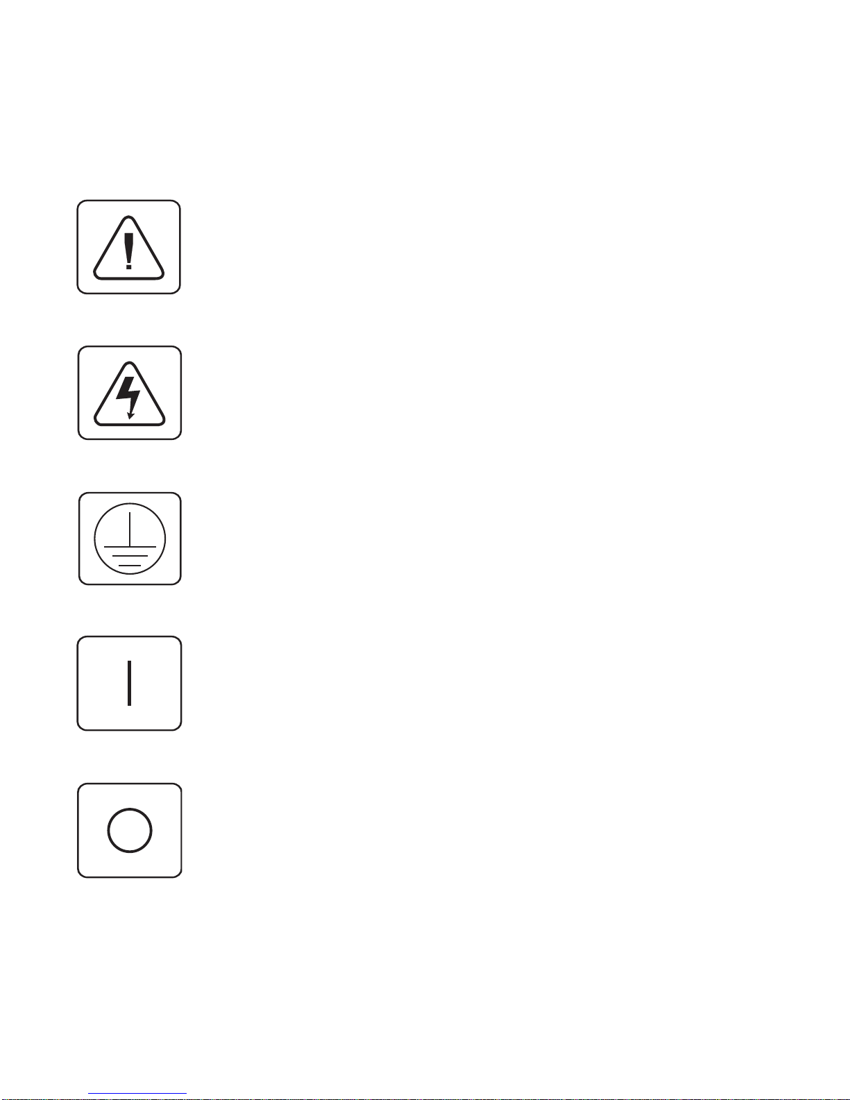
The XP4040 Unit
Front Access Desktop Model:XP4040D
The front panel of a front access XP4040 unit has 9 connectors as follows:
General overview of
Front and Rear Access
models
These connectors are used to attach a keyboard, monitor, mouse, microphone,
speakers and serial device to the front panel of the XP4040. Peripherals
attached to the front of the box make up your local console.
Each front access XP4040 unit supports up to 14 modules. The first slot on the
far left side of the XP4040D (viewed from the rear) contains the local console
●
PS/2 Keyboard
●
PS/2 Mouse
●
Serial Mouse
●
Macintosh
●
Sun
●
VGA Video
1
●
Serial Port
●
Microphone
●
Speakers
Page 8
interface (LCI) module. The LCI comes pre-installed in the unit. The remaining 13 slots in the unit may be configured as user consoles, attached computers, power control or expansion modules.
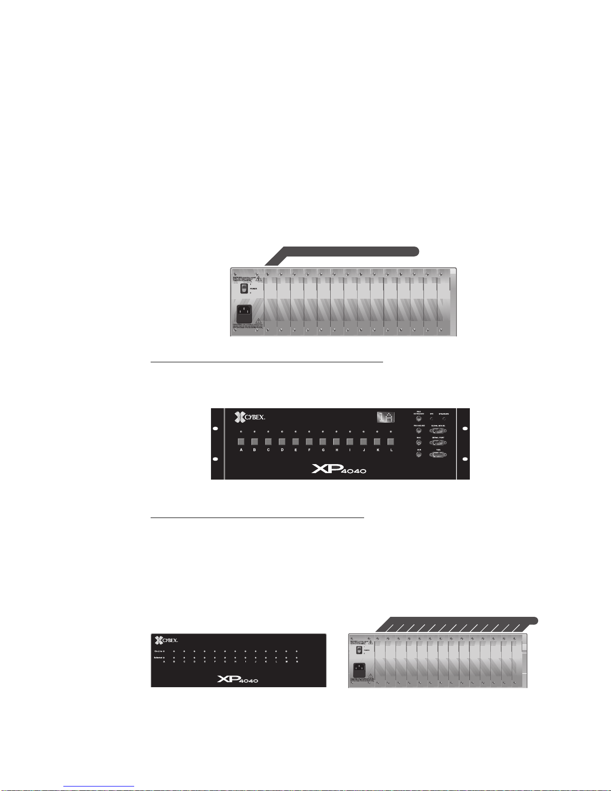
There are 12 push-buttons on the front panel labeled A through L. These
buttons select the active computer for the local console. The indicator lights
(LEDs) over each push-button reflect the type of activity, if any, that is taking
place on each attached computer. The alphanumeric display in the upper right
hand corner of the front panel shows which computer channel is currently
selected by the local console. Only the local console utilizes the push-buttons
and alphanumeric display. Secondary consoles, which connect to the XP4040
through the rear of the unit, select their active computer via the keyboard.
Secondary consoles, like the local console, have access to every computer in
the XP4040 system.
LCI MODULE (FRONT ACCESS MODEL ONLY)
LCI MODULE (FRONT ACCESS MODEL ONLY)
AC INPUT
90-240 VAC, 47-63 Hz
1 AMP FAST BLOW
250 VAC
Front Access Rack Mount Model:XP4040R
Cybex also offers a front access model designed for 19 inch rack use. It
supports all the features of the XP4040D Front Access unit.
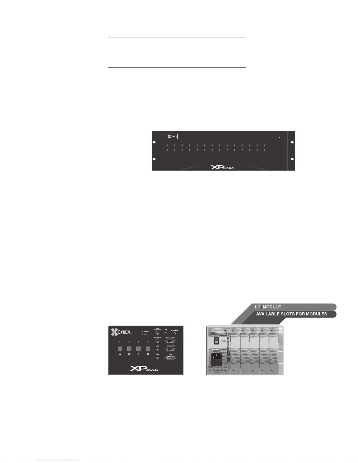
Rear Access Desktop Model:XP4040ED
The front panel of a rear access model XP4040E features LEDs only. These
LEDs reflect the power and selection status of all of the modules in that unit.
There are no connectors or alphanumeric display on the front of the unit.
There is no LCI (local console interface) module inside the unit. All 14 slots
are available for the installation and configuration of any module in the
system. All users connect through the rear of the unit and change computer
channels via keyboard switching.
AVAILABLE SLOTS FOR OPERATION MODULES
AVAILABLE SLOTS FOR OPERATION MODULES
AC INPUT
90-240 VAC, 47-63 Hz
1 AMP FAST BLOW
250 VAC
2
Page 9
Rear Access Rack Mount Model:XP4040ER
Cybex also offers a rear access model designed for 19 inch rack use. It supports
all the features of the XP4040E rear access unit.
Rear Access Rack Mount Model:XP4080ER
The XP4080ER rear access rack mount model supports all of the features of the
XP4040ED and XP4040ER models. Additionally, with this model, users can
access up to eight computers simultaneously and independently instead of the
four supported by XP4040 models. Used primarily in larger configurations
utilizing the XP4400 chassis, this model reduces the overall number of
XP4040 units required in the system
Power
On-Line
Selected
abcdefghijklmn
The XP4010 Unit
Differences between the
XP4010 and XP4040
systems
The XP4010 unit looks and functions like a front access XP4040D model with
the following exceptions:
1. An XP4010 system supports a maximum of five modules: the local user
console, pre-installed in the XP4010, and four additional modules which
can be configured as additional user consoles, attached computers, or
expansion modules.
2. The XP4010 front panel does not support an alphanumeric display.
3. The XP4010 is available in a front access desktop model only. Kits are
available for rack mounting. (RMK 19,20,21)
3
Page 10
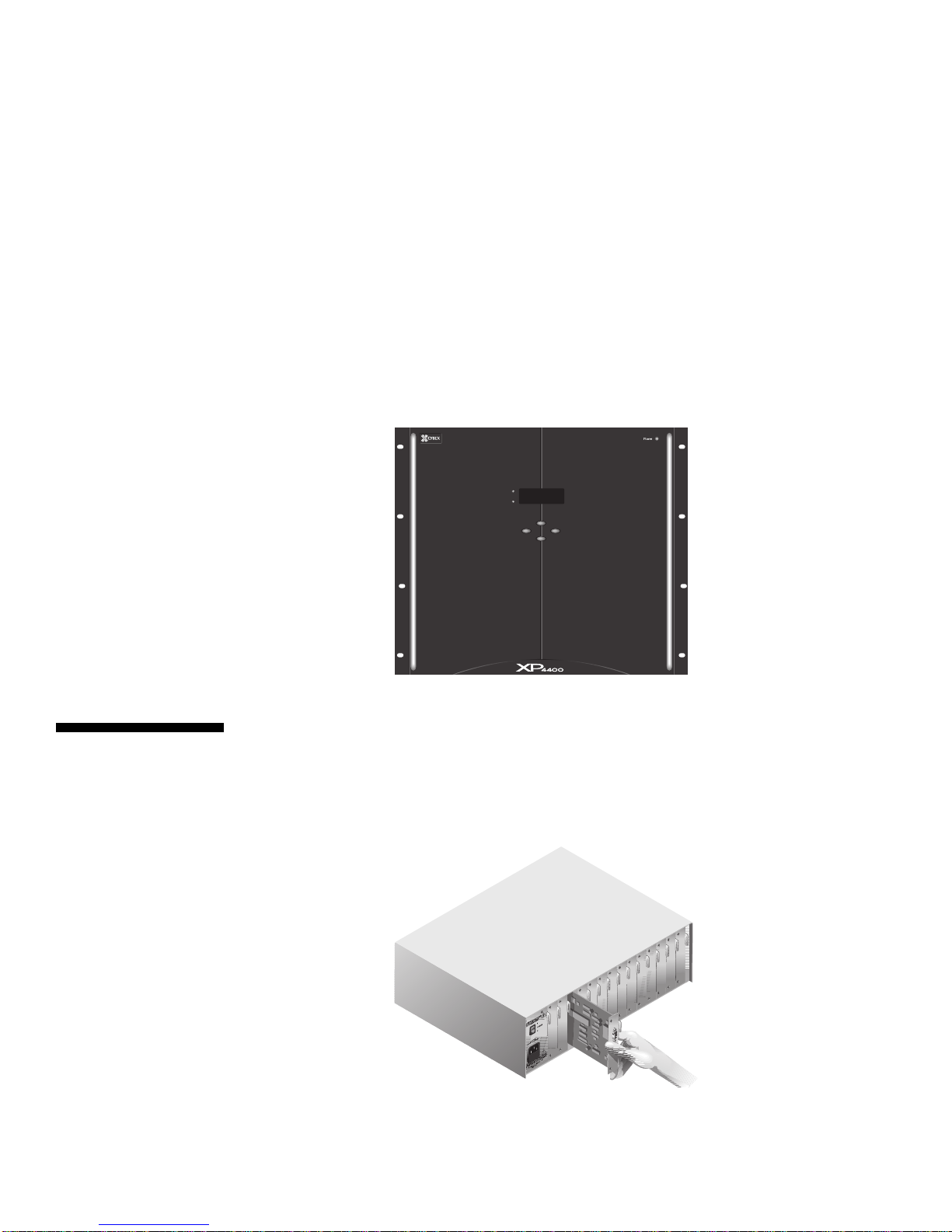
The XP4400 Unit
The XP4400 chassis is designed to accommodate larger XP system installations.
By channeling expansion signals from XP4040 users to attached computers,
the XP4400 enables large configurations with fewer XP4040 units, transmitter/
receiver cards and cables in the system. The XP4400 consists of a 9U high
chassis, containing two power supplies, two fan assemblies and a user specified
number of XP4400 transmitter and receiver modules. There are no users or
computers attached directly to this unit. There is an LCD display on the front
panel for the internal menuing system and four buttons that control menu
selections and operations.
Each module contains 16 sets of video and keyboard/mouse ports, enabling a
module to attach to as many as 16 XP4040 expansion ports, using two category
5 cables each. The XP4400 holds up to nine transmitter or receiver modules
per chassis. For more information on the XP4400, see Chapter 6.
Operation
Modules
Depending on the chassis used, an XP4000 Series unit can support from 4 to
up to 14 individual operation modules, including the local console module, if
applicable. Modules may be ordered in any combination required, and are
easily installed by sliding them gently through the rear of the unit. See the
diagram below.
Basic modules are used to attach users and computers to the XP4000 system.
Advanced modules are used for linking multiple XP4000 Series units together,
power control and terminal emulation.
4
Page 11
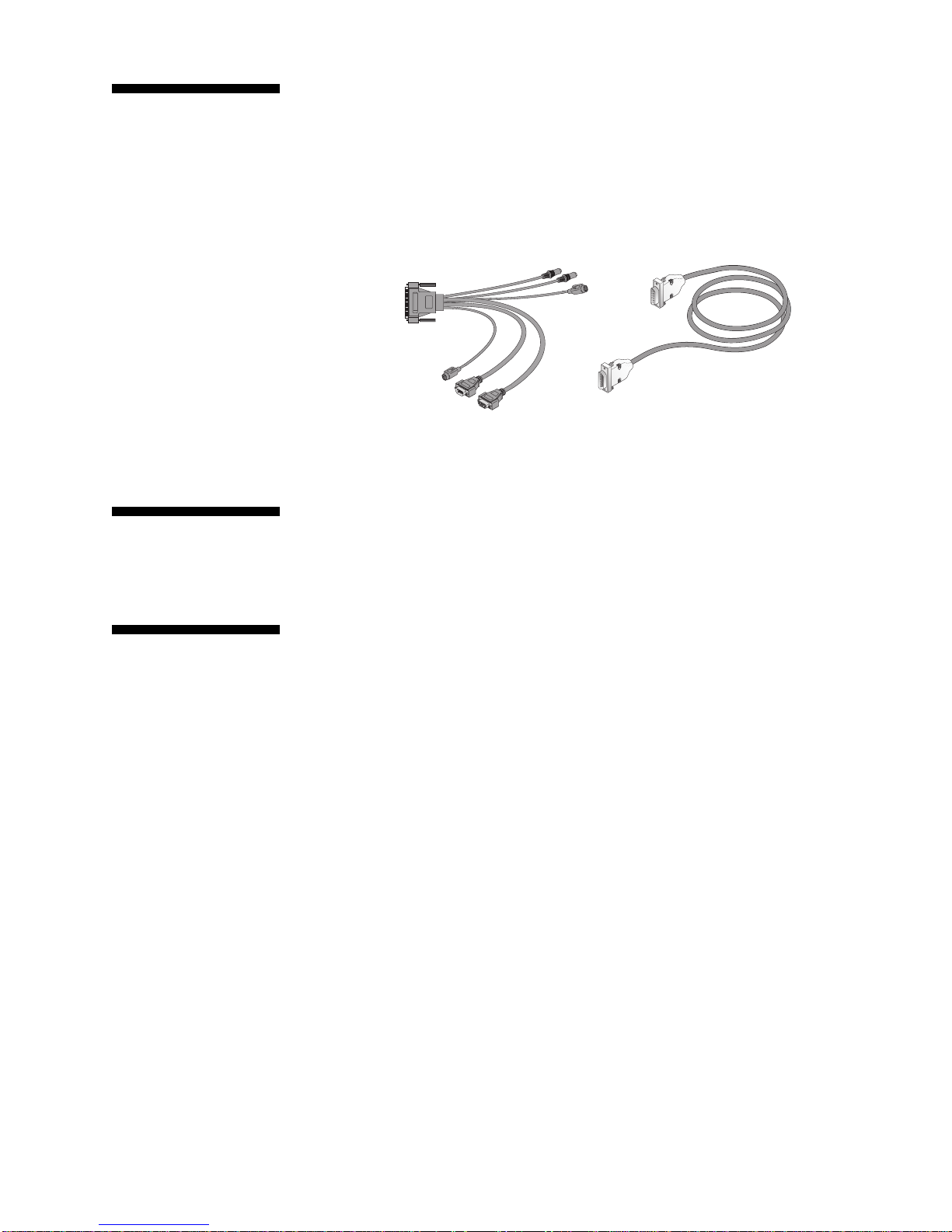
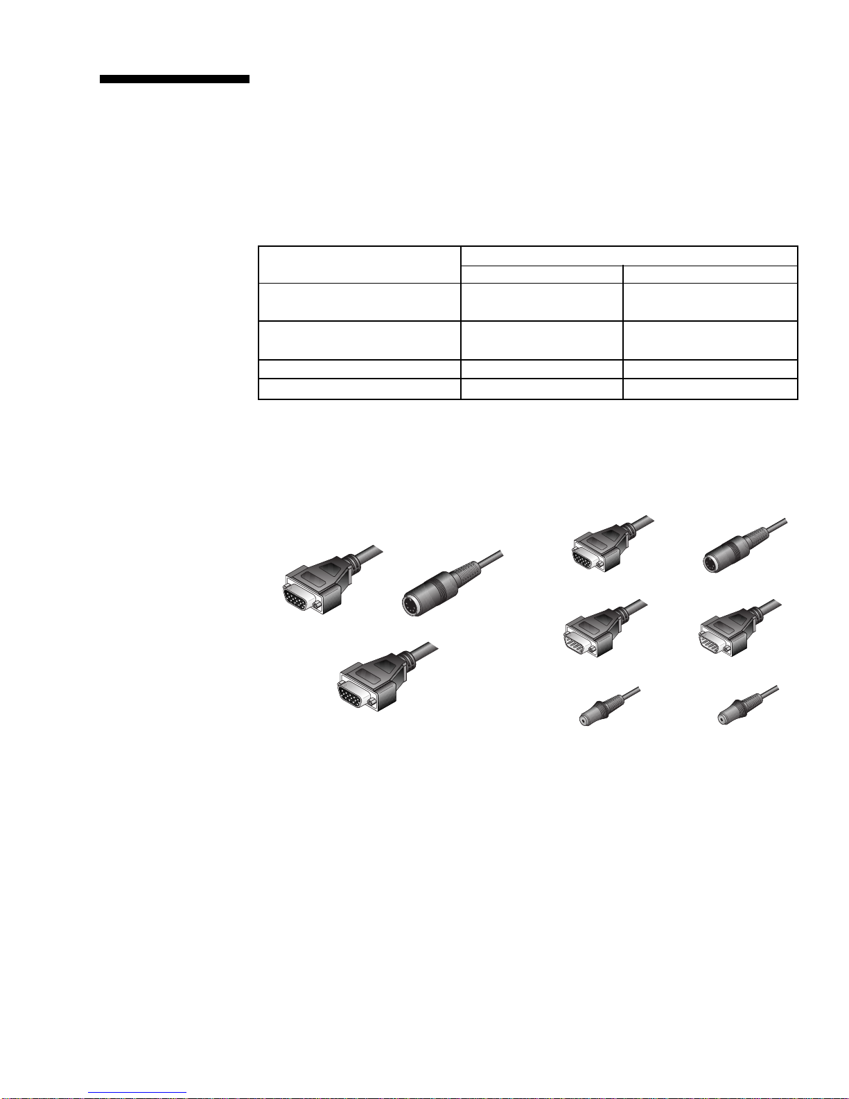
Cables
Each operation module, except the LCI, requires a cable to connect it to an
attached computer, user console, or other XP4000 Series unit. Computer
interface cables connect computers to the XP4000 Series unit. User interface
cables connect users to the unit. Expansion cables may be as long as 250 feet
and connect expansion units together. Typical cables are shown below.
C
XP4000 Series
Complements
Features and
Benefits
AutoBoot capability
Built-in scanning
capabilities
User interface cables
(CPIUF-10 shown)
CLX expansion cable
(used in expansion
systems only)
XP4000 Series complements are optional products that work in conjunction
with the XP4010/XP4040 and XP4080 to give your system added flexibility
and control. For a detailed description of available complement products, see
Chapter 11.
The XP4000 Series AutoBoot feature boots all of your attached computers
during initial power-up or after a power failure. All computers are booted
transparently and simultaneously, eliminating the need for operator
intervention. Computers may be powered up one at a time or all at once.
KeyScan, a built-in scanning feature, allows you to automatically monitor or
scan all of your computer channels sequentially without intervention. When
KeyScan detects keyboard or mouse activity, scanning is suspended until all
activity stops. Scanning then resumes with the next computer in sequence. The
length of time each computer channel remains on the screen, or dwell time, is
configurable and can be changed at any time.
Multiplatform
The XP4000 Series adds multiplatform capabilities to your switching system
by simultaneously supporting any combination of PC, Macintosh, Sun, RS/
6000, Silicon Graphics or Hewlett-Packard computers in the same system.
Along with the ability to access many different types of computers and
workstations, you can now use any platform's peripherals to do it! You can use
any type of keyboard and mouse to access any type of computer in the system.
For example, a PC keyboard and mouse can operate a Sun server as easily as
a Sun keyboard and mouse will operate an attached PC.
Multiuser
Another useful feature is the multiuser capability of the XP4000 Series.
Instead of just one user having access to many different attached computers,
these products allow multiple users simultaneous access to different computers
in the system. This is called “matrix switching”. So, a system with four users
accessing four different computers would be a 4 x 4 matrix.
5
Page 12
If two or more users need access to the same computer, they can ‘share’ access
to it through the XP units. Sharing means that multiple users can switch to the
same computer at the same time. Everyone can see that computer's video, but
only one can enter data at any given moment.
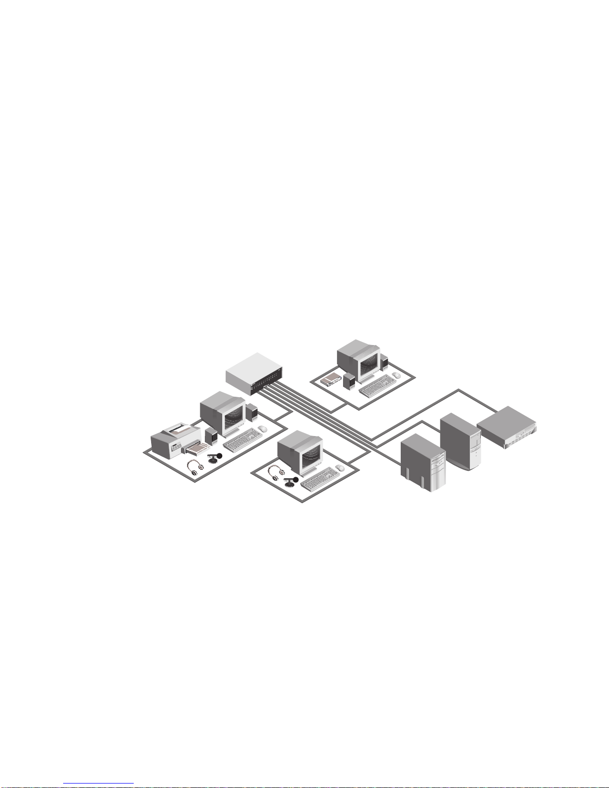
Expansion capability
Multimedia
Local User Console
The primary user console has access
to every computer in the system, as
well as control over the push-button
front panel of the XP4000 Series Unit.
If your total number of computers and users is greater than 14, use our
expansion modules. Connecting an expansion transmitter in one XP Series unit
to an expansion receiver in another XP Series unit lets you combine multiple
units in one system. Control thousands of computers from one set of peripherals!
Transmitters and receivers are available with Cybex proprietary or industry
standard category 5 UTP cable connections. Category 5 cables can be ordered
in standard or extended distance versions. With Cybex or UTP standard
distance cabling, each XP Series unit can be up to 250 feet apart; a user and the
farthest accessible computers can be up to 500 feet apart.
Users in an XP Series system also have the option of multimedia support.
Every user has access to a dedicated keyboard, mouse and video monitor as
well as optional microphone and stereo speaker connections.
Secondary User Console
Secondary user consoles have access
to every computer in the system.
Mac keyboard, mouse, &
multisync* monitor
Channel C:
Sun Workstation/server
PC keyboard, mouse,
& multisync* monitor
On-screen management
Multi-level security
Serial port
Channel D:
IBM Compatible PC
Secondary User Console
Secondary user consoles have access
to every computer in the system.
Sun keyboard, mouse, &
multisync* monitor
FIGURE 1-1
Channel E:
Macintosh Computer
*Monitor must be capable of synchronizing with any attached computer’s video output.
For on-screen management and multi-level security, try the XPDU deluxe user
module. Name your servers, then select them from a pop-up menu. Quick edit
capability lets you change channel name or address on the fly. Control features
allow you to manage scanning and broadcast operations on-screen as well.
On-screen management also supports multi-level security with password
protection. Control how much access users have to each computer in your data
center. An additional feature is the optional logout after a user defined period
of inactivity. When the timeout is reached, the current channel is deselected
and the screen goes blank. Users must login again to access system computers.
A serial port is also available, allowing for the use of a printer or similar serial
device at the console. This serial port can optionally be used as a serial access
port to the XP Series Control Menu. From this menu, you can determine your
6
Page 13

revision level, system configuration and even upgrade the firmware to keep
your system current at all times.
FLASH upgrading
Field-replacable
plug-in modules
Keep Alive capability
Individual power
control
Limitations &
Restrictions
FLASH technology allows the XP Series firmware to be updated without ever
removing a module or even powering down the system. New firmware revisions
can be uploaded into the XP4000 Series through the serial port. The latest
firmware revisions are available to all users through Technical Support or via
the internet.
Since the XP Series units are component based products, all modules are fieldreplaceable plug-in boards. They can be added or replaced without
disassembling or even powering down the switch or attached computers. This
capability makes installation, configuration and maintenance much simpler.
The "Keep Alive" capability of the XP Series allows attached computers to power
the computer modules in the event of a power failure. Keeping the modules
powered up in an emergency prevents the computers from locking up needlessly.
The optional ReBoot xP allows you to control the power to computers in your
XP Series system individually. No matter where a system computer is located,
you can cycle the power, or “reboot”, an attached computer from your XP
Series unit.
The following models of mice have been tested and are known to be compatible
with the XP Series:
Mouse support
Use capable multisync
monitors only
Use Cybex supplied
cables only
Speaker support
Microphone support
Microsoft Serial-PS/2 mouse Kensington PS/2, ADB
Microsoft OEM style serial mouse Mouse Systems
Microsoft Intellimouse Logitech Mouseman/Trackman
Sun Microsystems Laser mouse IBM PS/2-style
Apple ADB mouse
Other manufacturers' mice generally operate with the XP Series. If you
experience problems using an untested mouse, contact Cybex Technical Support
with the manufacturer and model number of the mouse.
Monitors at all consoles must be capable of synchronizing with any attached
computer’s video rate. If you are unsure whether your monitors are of the
multisync type, consult the monitor documentation or contact your dealer.
Use only Cybex supplied cable with the XP Series. Poorly constructed or
miswired cabling will diminish video quality and possibly damage equipment.
Cybex warranties do not apply to damage resulting from user supplied cables.
The XP4000 Series supports all externally powered speakers using 3.5 mm
miniplugs. Use powered speakers with the XP Series for best performance.
The XP4000 Series supports “mono” microphones with 3.5 mm miniplugs.
Powered microphones are not recommended; if a computer channel is selected
that supplies power to the microphones, the microphone volume may be muted
on that channel.
Serial support
The XP4000 Series supports RS-232 serial devices using hardware or inband
flow control: hardware up to 9600 Baud, inband to 115200 Baud.
7
Page 14

Safety
Precautions
To avoid potential video or keyboard problems when using Cybex
products:
Check environment
Ensure proper
grounding
• If the building has 3-phase AC power, ensure that the computer and
monitor are on the same phase. For best results, they should be on the
same circuit.
• Use only Cybex-supplied cable. Cybex warranties do not apply to damage resulting from user-supplied cable.
To avoid potentially fatal shock hazard and possible damage to
equipment, please observe the following precautions:
• Do not use a 2-wire extension cord in any Cybex product configuration.
• Test AC outlets at computer and monitor for proper polarity and grounding.
• Use only with grounded outlets at both the computer and monitor. When
using a backup power supply (UPS), power the computer, the monitor
and the XP4000 Series unit off the supply.
• With the exception of adding or removing original Cybex manufactured
modules in accordance with written Cybex instructions, the XP4000 Series
unit and all attached computers should be powered down before servicing
the unit. Always disconnect the power cord from the unit.
Note: The AC inlet is the main disconnect.
Rack Mount Safety Considerations
• Elevated Ambient Temperature: If installed in a closed rack assembly,
the operation temperature of the rack environment may be greater than
room ambient. Use care not to exceed the rated maximum ambient temperature of the unit.
• Mechanical Loading: Mounting of the equipment in the rack should be
such that a hazardous condition is not achieved due to uneven mechanical loading.
• Circuit Overloading: Consideration should be given to the connection of
the equipment to the supply circuit and the effect that overloading of
circuits might have on overcurrent protection and supply wiring. Consider equipment nameplate ratings for maximum current.
• Reliable Earthing: Reliable earthing of rack mounted equipment should
be maintained. Pay particular attention to supply connections other than
direct connections to the branch circuit (e.g. use of power strips).
Nameplate Rating: This product is rated 100-240 V ac, 50/60 Hz. All components except the XP4400 are rated 1.6A (single component power supply) or 3.2A (dual component power supply). XP4400 is rated at 7 amps.
8
Page 15
2
Installing User Interface
Modules
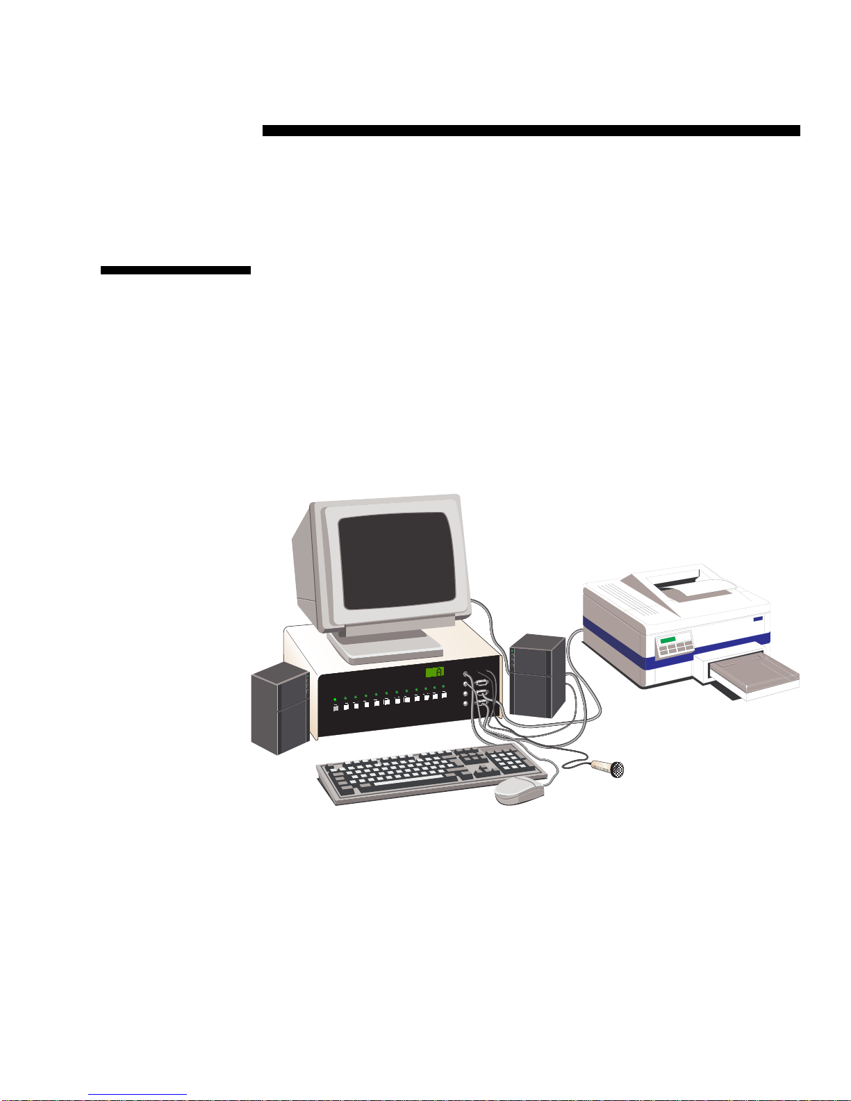
Connecting
the Local
Console
Peripherals
(Front Access
Model Only)
The keyboard, monitor, mouse, serial device, speakers and microphone at the
local console connect directly into either the corresponding ports on the front
panel of your XP4000 Series unit or the user interface cable for your XPLU
or XPDU card. No additional cables are required.
Any platform's keyboard and mouse can be plugged into the local console in
any combination. However, do not connect more than one keyboard, monitor
or mouse into the front of the unit. For example, you may use a Macintosh
mouse and a Sun keyboard at the workstation at the same time but you cannot
connect two keyboards or two mice into the front of the unit simultaneously.
SPEAKER
MIC
S
PS/2
KEYBOARD
PS/2
SERIAL MOUSE
MOUSE
L
K
J
I
H
G
F
E
D
C
B
A
SERIAL PORT
MAC
VGA
SUN
R
9
Page 16
Secondary
Console
Modules
A secondary console module is one of the two types of user modules. While
the primary console peripherals connect through the front panel of the unit
(discussed in the previous section), secondary console modules have the
peripherals connected through the rear of the module. Currently we offer
versions with on-screen display capabilities (XPDU) and without (XPLU).
Installing the
Secondary
Console
Modules (XPDU
and XPLU)
The XPDU and XPLU modules are installed identically. There are no DIP
switches or jumpers to configure on either module
1. Position the XP4000 Series unit so that the rear panel is facing you.
Choose an available slot. An available slot will have a solid panel covering the opening to the unit, with no connectors showing through it.
NOTE: For front access models, the LCI module, located to the far left
of the unit (viewed from rear), is covered by a solid panel but IS NOT
an available slot. Only the LCI module can be installed in this slot.
LCI MODULE (FRONT ACCESS MODEL ONLY)
LCI MODULE (FRONT ACCESS MODEL ONLY)
AVAILABLE SLOTS FOR OPERATION MODULES
AVAILABLE SLOTS FOR OPERATION MODULES
AC INPUT
90-240 VAC, 47-63 Hz
1 AMP FAST BLOW
250 VAC
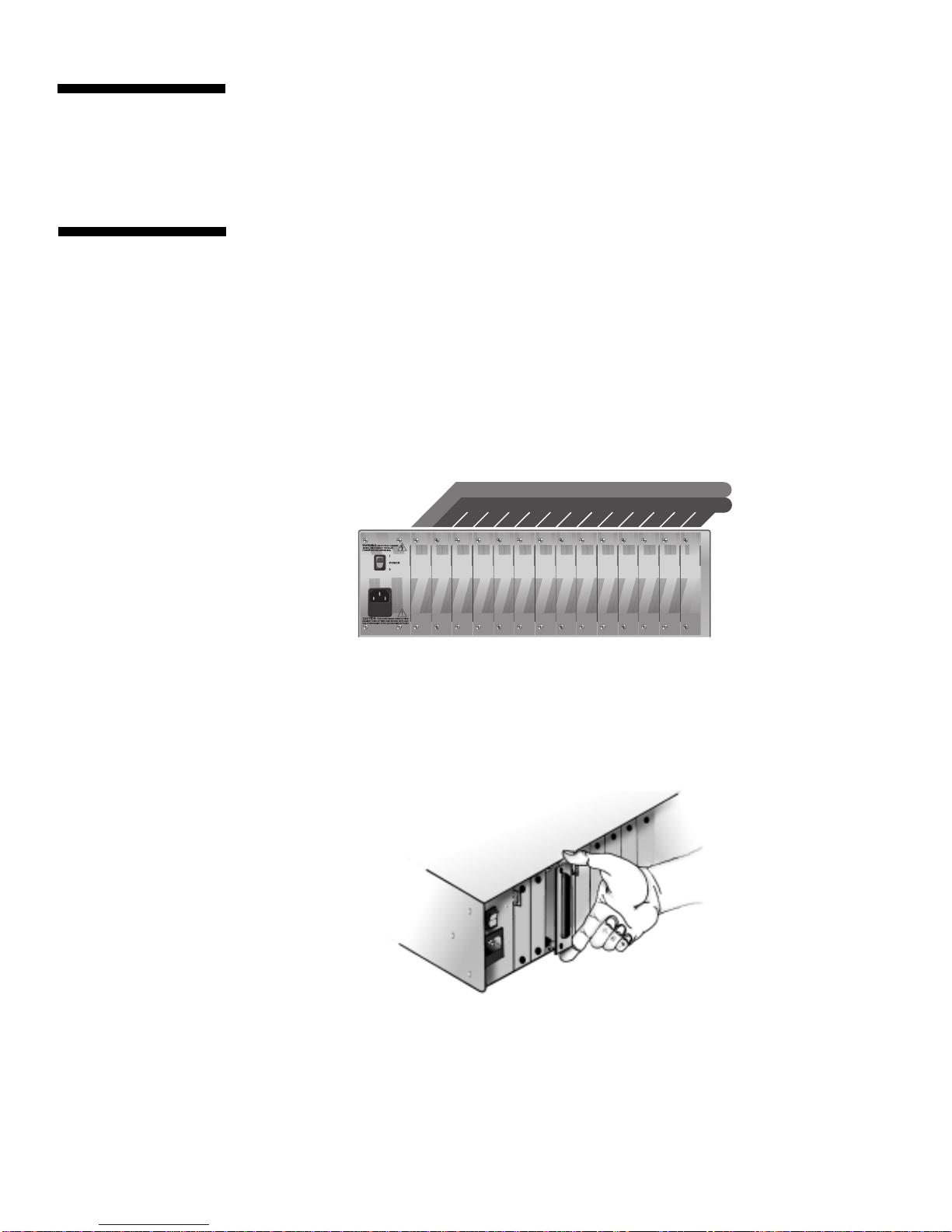
2. Remove the panel covering the available slot by unscrewing the two
Phillips-head screws on the rear of the unit that hold the panel in place.
3. Slide the new user interface (XPDU/XPLU) module gently into the open
slot of the XP4000 Series unit until the 62-pin connector lines up flush
with the back of the unit. See the diagram below.
4. Retighten the holding screws completely. DO NOT overtighten.
5. Fill out the XPDU/XPLU Configuration Chart in Appendix A for each
module as you install it.
Follow the above procedure for every XPDU/XPLU module in your system.
10
Page 17
Connecting the
User Interface
Cables (XPDU
and XPLU)
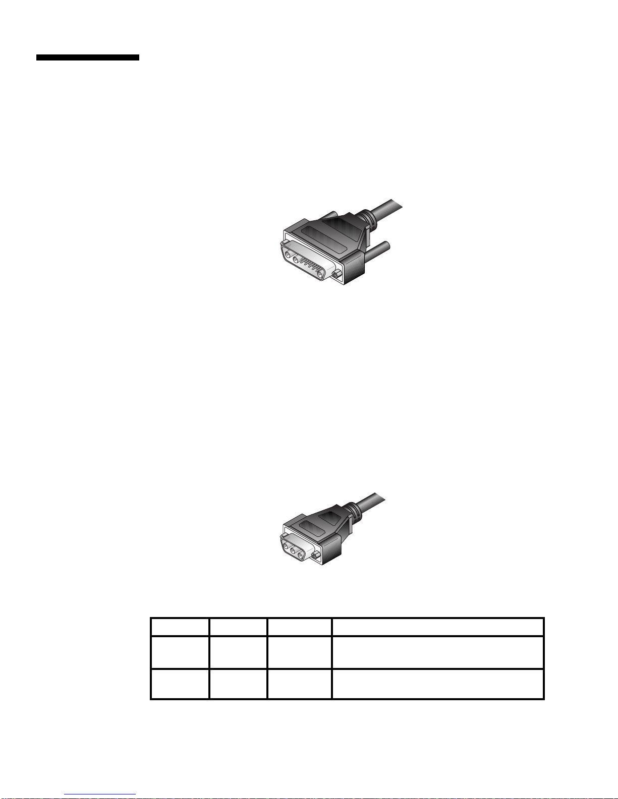
User interface cables connect your secondary consoles to the XP4000 Series
unit. You will have a set for each secondary console in the system. These
cables are a user specified length with a 62-pin D-shaped male connector on
one end. The other end will have from two to six connectors, depending on the
options you ordered (See the table below). Use the instructions on the
following pages which apply to the type of peripherals you are attaching, and
repeat the process for each secondary console in the system. User interface
cables for the XPDU and XPLU user modules are identical
Peripherals User interface cables
Standard Multimedia
IBM AT-compatible keyboard CPMU-x CPMUF-x
with Serial mouse
PS/2-compatible keyboard CPIU-x CPIUF-x
with PS/2 mouse
Macintosh CPAU-x CPAUF-x
Sun CWSU-x CWSUF-x
Replace x with the distance cable you ordered.
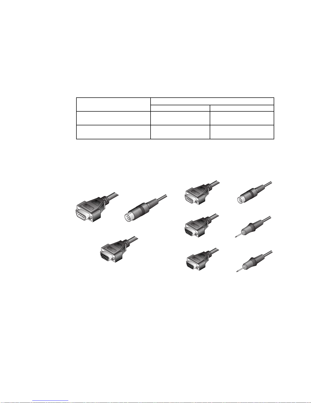
For IBM AT-style keyboard, monitor and Serial mouse
1. Your user interface cables for these peripherals will be labeled either
CPMU-x or CPMUF-x , depending on the options you ordered. Use the
cable diagrams below to locate the correct cable.
VGA VIDEO
VGA VIDEO
SERIAL MOUSE
CPMU-x CABLE CPMUF-x CABLE
KEYBOARD
SERIAL MOUSE
(yellow band)
MICROPHONE
(blue band)
KEYBOARD
SERIAL PORT
SPEAKERS
2. At your secondary console, plug your keyboard, serial mouse and monitor
connectors into the three matching connectors on the user interface cable.
If you have the CPMUF-x series cable, you will have three additional
connectors: two small connectors for a microphone and speakers, and a 9pin D-shaped serial connector for a serial port. The microphone connector
is denoted by a blue band around its cable; the serial mouse connector is
denoted by a yellow band. Plug your peripheral connectors into the
matching connectors on the user interface cable.
3. Attach the user interface cable to the unit by plugging the 62-pin connector into the rear of any available secondary console module. Ensure that
the connector is firmly seated, then tighten the thumbscrews.
11
Page 18

For PS/2-style keyboard, monitor and PS/2 mouse
1. Your user interface cables for these peripherals will be labeled either
CPIU-x or CPIUF-x , depending on the options you ordered. Use the cable
diagrams below to locate the correct cable.
KEYBOARD
SERIAL PORTPS/2 MOUSE
SPEAKERSMICROPHONE
VGA VIDEO
VGA VIDEO
KEYBOARD
(yellow band)
PS/2 MOUSE
(yellow band)
(blue band)
CPIU-x CABLE CPIUF-x CABLE
2. At your secondary console, plug your PS/2-style keyboard, PS/2 mouse
and monitor connectors into the matching connectors on the user interface
cable. The mouse connector is denoted by a yellow band around its cable.
If you have the CPIUF-x series cable, you will have three additional
connectors: two small connectors for a microphone and speakers, and a 9pin D shaped serial connector for a serial port. The microphone connector
is denoted by a blue band around its cable. Plug your peripheral connectors into the matching connectors on the user interface cable.
3. Attach the user interface cable to the unit by plugging the 62-pin connector into the rear of any available secondary console module. Ensure that
the connector is firmly seated, then tighten the thumbscrews.
NOTE: You may use your SGI, RS/6000 or HP workstation monitor with an
XP4000 Series unit if it will function with all of your attached computers/
workstations. See “Using Non-multisync Monitors” later in this chapter.
12
Page 19

For Macintosh keyboard and mouse
1. Your user interface cables for these peripherals will be labeled either
CPAU-x or CPAUF-x , depending on the options you ordered. Use the
cable diagrams below to locate the correct cable.
ADB
SPEAKERS
SERIAL PORT
VGA VIDEO
VGA VIDEO
ADB
MICROPHONE
(blue band)
SERIAL MOUSE
SERIAL MOUSE
(yellow band)
CPAU-x CABLE CPAUF-x CABLE
2. At your secondary console, plug your Mac keyboard/mouse and VGA
monitor connectors into the two matching connectors on the user interface cable.
NOTE: For users requiring multi-button mice, a serial mouse connector is
also provided.
If you have the CPAUF-x series cable, you will have three additional
connectors: two small connectors for a microphone and speakers, and a 9pin D-shaped serial connector for a serial port. The microphone connector
is denoted by a blue band around its cable; the serial mouse connector is
denoted by a yellow band. Plug your peripheral connectors into the
matching connectors on the user interface cable.
3. Attach the user interface cable to the unit by plugging the 62-pin connector into the rear of any available secondary console module. Ensure that
the connector is firmly seated, then tighten the thumbscrews.
NOTE: You may use your Macintosh monitor with an XP4000 Series unit if it
will function with all of your attached computers. See “Using Non-multisync
Monitors” later in this chapter.
13
Page 20

For Sun keyboard and mouse
1. Your user interface cables for these peripherals will be labeled either
CWSU-x or CWSUF-x , depending on the options you ordered. Use the
cable diagrams below to locate the correct cable.
VGA VIDEO
KEYBOARD/
MOUSE
VGA VIDEO
MICROPHONE
(blue band)
SERIAL PORT
KEYBOARD/MOUSE
SPEAKERS
CWSU-x CABLE CWSUF-x CABLE
2. At your secondary console, plug your Sun keyboard/mouse and VGA
monitor connectors into the two matching connectors on the user interface cable.
If you have the CWSUF-x series cable, you will have three additional
connectors: two small connectors for a microphone and speakers, and a 9pin D-shaped serial connector for a serial port. The microphone connector
is denoted by a blue band around its cable. Plug your peripheral connectors into the matching connectors on the user interface cable.
3. Attach the user interface cable to the unit by plugging the 62-pin connector into the rear of any available secondary console module. Ensure that
the connector is firmly seated, then tighten the thumbscrews.
NOTE: You may use your Sun monitor with an XP4000 Series unit if it will
function with all of your attached computers/workstations. See ‘Using Nonmultisync Monitors’ later in this chapter.
14
Page 21

Using
Non-multisync
Monitors
Using your SGI, RS/6000 or HP Workstation Monitor
1. You may use your SGI, RS/6000 or HP workstation monitor with an
XP4000 Series unit if it will function with all of your attached computers/
workstations. In order to connect your monitor, you will need a video
adaptor from Cybex. These devices adapt the VGA video output to your
workstation monitor's input. If you do not have one of the adaptors listed
below, contact our Sales Department.
Monitor Connector Type Adaptor Type
BNC VAD-19
13W3 (SGI) VAD-14
3C3 VAD-20
13W3 (RS 6000) VAD-22
Using your Macintosh Monitor with an XP4000 Series unit
1. You may use your Macintosh monitor with an XP4000 Series unit if it will
function with all of your attached computers. In order to connect this type
of monitor, you will need a VAD-16 video adaptor from Cybex. This
device adapts the VGA video output to your Mac monitor's input. If you
do not have this adaptor, contact our Sales Department.
2. Follow the instructions above for the installation of a Macintosh keyboard
and mouse, making sure to attach the VAD-16 adaptor between your user
interface cable and your Mac monitor cable.
Using your Sun Monitor with an XP4000 Series unit
1. You may use your Sun monitor with an XP4000 Series unit if it will
function with all of your attached computers/workstations. In order to
connect this type of monitor, you will need a VAD-13 video adaptor from
Cybex. This device adapts the VGA video output to your Sun monitor's
input. If you do not have this adaptor, contact our Sales Department.
2. Follow the instructions above for the installation of a Sun keyboard and
mouse, making sure to attach the VAD-13 adaptor between your user
interface cable and your Sun monitor cable.
Changing XPDU settings for Non-PC Monitors
In some cases you may not see video the first time you power up a Sun or Mac
Monitor attached to an XPDU. If this happens:
1. Hold down the <CTRL><ALT><Shift> and <M> keys at one time.
2. The monitor will begin to cycle through settings. When you see video on
your screen, press the <ENTER> key.
Your monitor should begin to work normally.
15
Page 22

16
Page 23
5
6
4
2
3
1
2
3
1
*
Attaching Computers to
3
Attaching a PC
Computer
XPAC module shown
an XP4000 Series Unit
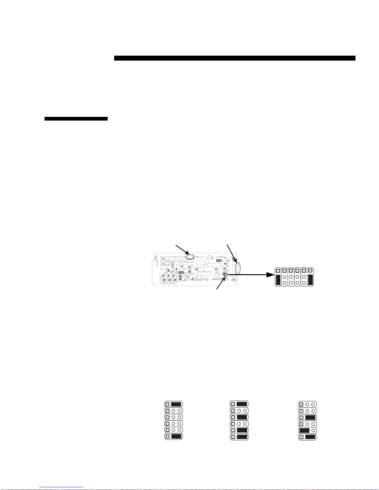
Before you connect your PC to the XP4000 Series unit, you will need to configure
and install your computer interface module. The XPAC, XPAB and XPAL
computer interface modules have one set of DIP switches to configure. The XPAC
and XPAB also have jumpers to configure. Follow the steps below to configure
each XPAC, XPAB or XPAL module that will be connected to a PC computer.
Configuring your computer interface (XPAC/XPAB) modules
Configuring the Jumpers
The jumpers on the XPAC/XPAB module are used to control the video
selection settings. The default is IBM VGA/SVGA video. If the computer you
are attaching supports this video mode, no adjustment is required and you may
proceed to the DIP switch settings.
DIP-SWITCH
ASSEMBLY
44-PIN
CONNECTOR
J1
J3
J5J6J4
J2
IBM VGA/SVGA
(DEFAULT)
J4
J3
J6
J5
J2
J1
1
2
3
Orient your XPAC/XPAB module so that the 44-pin connector is to your right
as shown above. Locate the jumpers on the lower right hand corner of the
board. The XPAC will contain JP1 - JP6; the XPAB module will only have
jumpers JP1 - JP5. Configure your XPAB module as you would an XPAC,
ignoring all references to JP6.
Use the diagrams below to configure the video settings for the PC computer
that you will attach to this computer interface module. You may wish to
consult your computer or video card reference manual for the video rates
supported by your computer.
* XPAC Modules only
3
1
2
1
2
3
4
5
6
*
IBM VGA/SVGA
VIDEO
JUMPERS
17
3
1
2
1
2
3
4
5
6
*
IBM XGA IIIBM XGA
Page 24
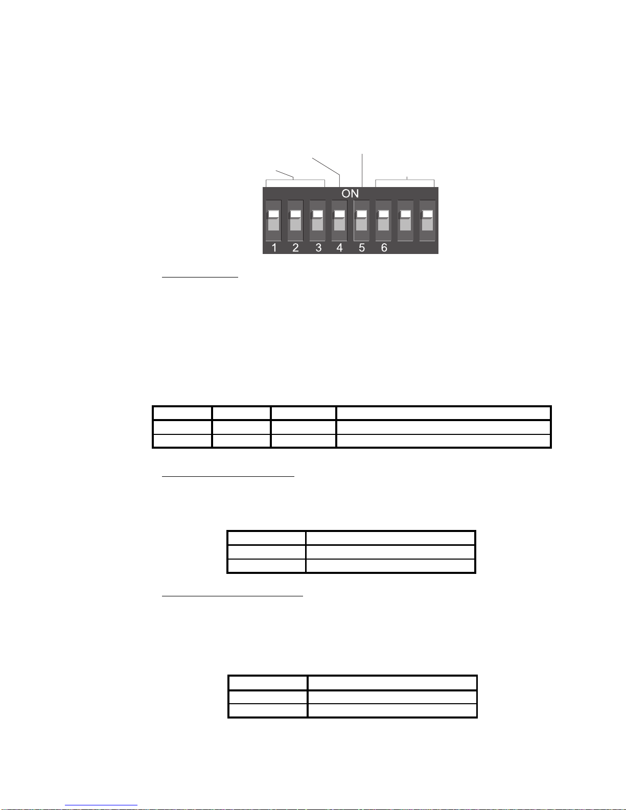
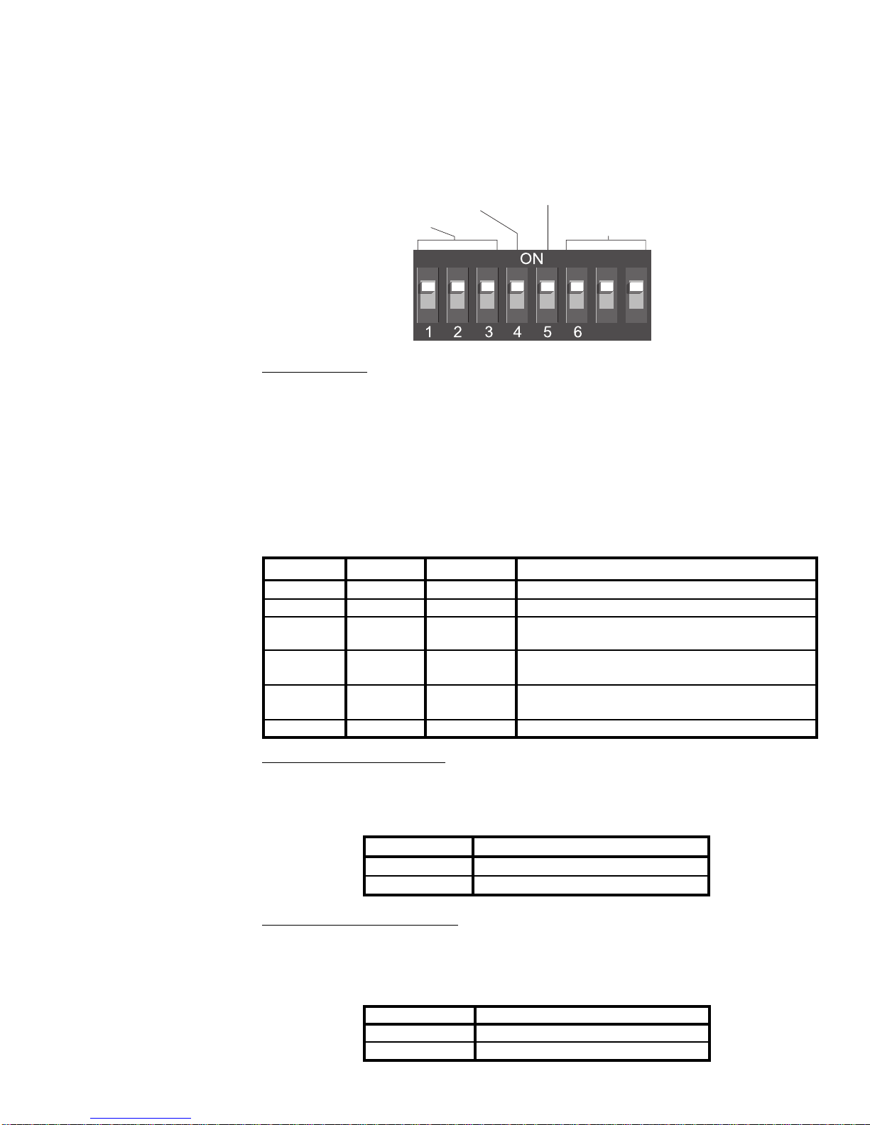
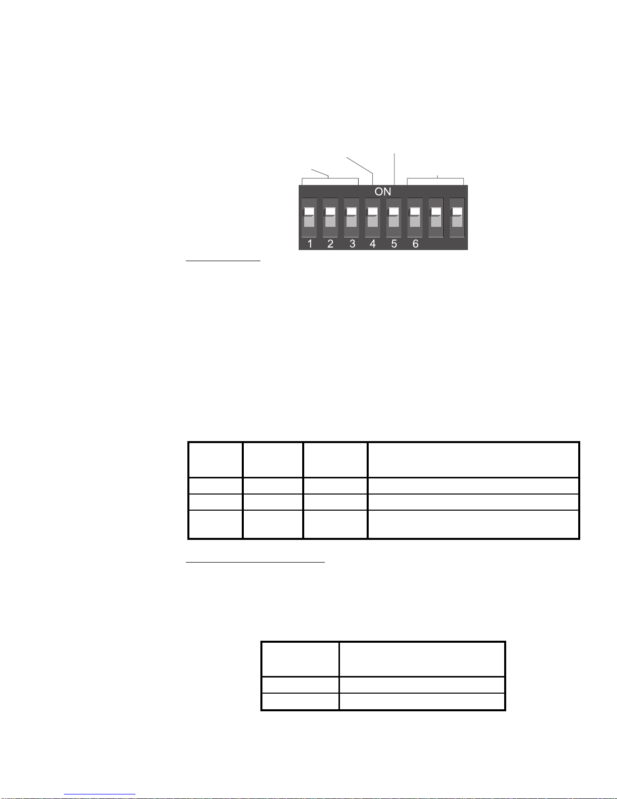
Configuring the DIP Switch (XPAC, XPAB and XPAL)
The DIP switch is used to configure three different features: video options and
sync, keyboard/mouse time-out and keyboard translation options (Mac only).
The diagram below shows the DIP switch, the positions used to configure each
of these features, and the default settings.
Keyboard/Mouse
Translation
Reserved
Video Options
Your XP4000 Series unit is factory set for PC video. No changes are needed
to switches 1 through 3 for normal PC video.
By default, a computer's video will be displayed for any console user that
switches to that channel. If you do not want a computer's video to be displayed,
you can disable the video for that channel. Additionally, if you are only
running your keyboard and mouse through the XP4000 Series unit, and your
video is independent of the system, you should select the option to disable the
video. See the table below.
Timeout
Video
7 8
Switch 1 Switch 2 Switch 3
Off Off Off Normal video (default)
On On On Video disabled
Function
Video Sync - XPAB only
Your XPAB card will attempt to automatically detect the sync for your
monitor. In some unique instances it will obtain the opposite of the settings.
Switching S7 to the on position will correct this. See the table below.
Switch 7
Off Autodetect (default)
On Reverse Autodetected Sync
Sync Mode
Keyboard/Mouse Time-out
While multiple consoles can view a computer's video at the same time, only
one station can have keyboard and mouse control at a time. The amount of time
that a console's keyboard and mouse must be inactive before another console
can take control is called the time-out. See the table below for the available
time-outs that can be configured.
Switch 4
Off 1 second (default)
On 10 seconds
Time
Note: Once your XPAC/XPAB module has been installed, you can change the
DIP switch setting at any time through a simple hot-key sequence. See Chapter
9, Advanced Operations for more information.
18
Page 25
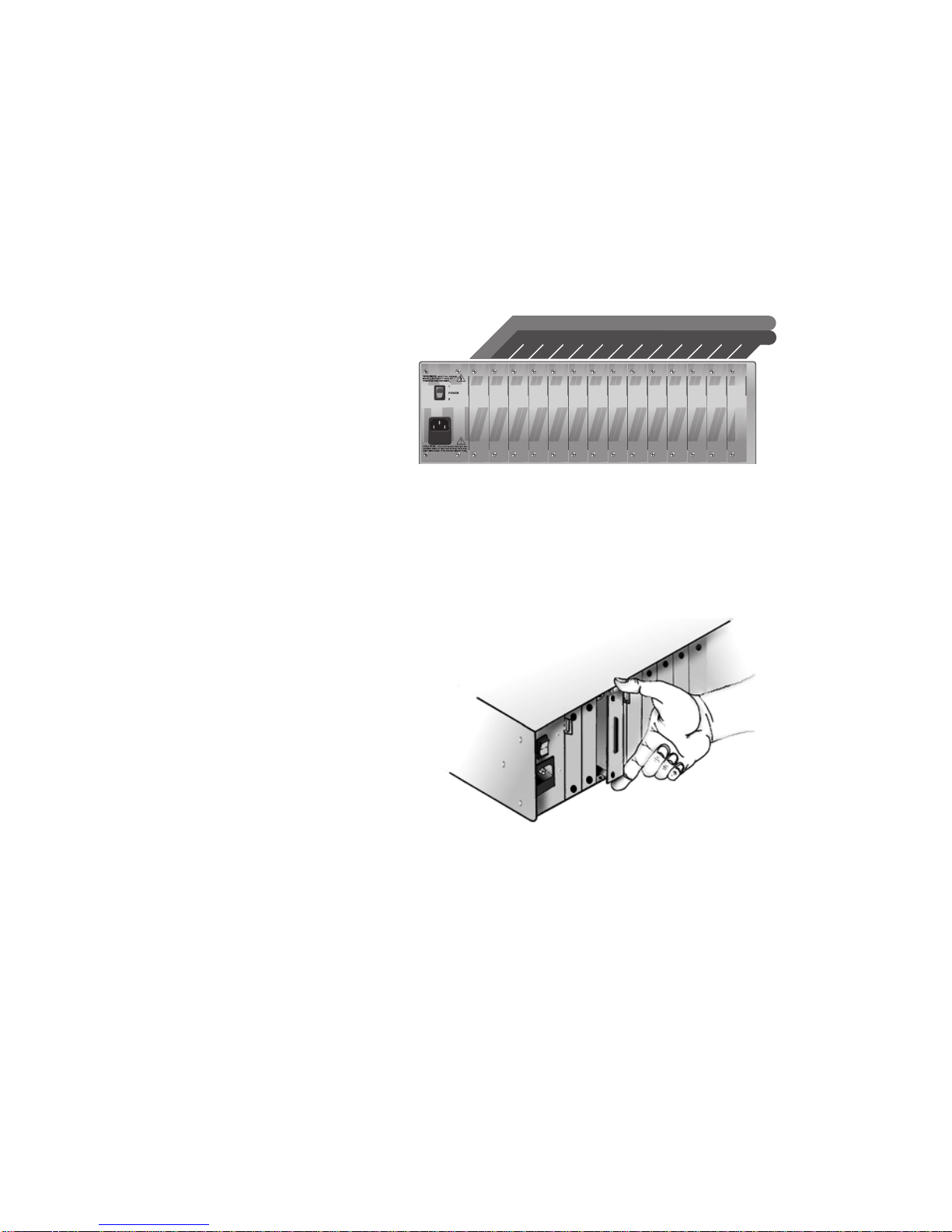
Installing the computer interface modules (XPAB and XPAC)
1. Position the XP4000 Series unit so that the rear panel is facing you.
Choose an available slot. An available slot will have a solid panel covering the opening, with no connectors showing through it.
NOTE: For front access models, the LCI module, at the far left of the
unit (viewed from rear), is covered by a solid panel but IS NOT an
available slot. Only the LCI module is installed in this slot.
LCI MODULE (FRONT ACCESS MODEL ONLY)
LCI MODULE (FRONT ACCESS MODEL ONLY)
AVAILABLE SLOTS FOR OPERATION MODULES
AVAILABLE SLOTS FOR OPERATION MODULES
AC INPUT
90-240 VAC, 47-63 Hz
1 AMP FAST BLOW
250 VAC
2. Remove the panel covering the available slot by unscrewing the two
Phillips-head screws on the rear of the unit that hold the panel in place.
3. Slide the new computer interface module gently into the open slot of
the unit until the 44-pin connector lines up flush with the back of the
unit. See the diagram below.
4. Retighten the holding screws completely. DO NOT overtighten.
5. Fill out the Configuration Chart in Appendix A for each module as you
install it.
Follow this procedure for every computer interface module in your system.
19
Page 26

Installing the computer interface modules (XPAL) with a PC
Follow steps 1-5 of the XPAB and XPAC installation instructions on the
previous page and then proceed with the following steps:
6. Place the LongView Transmitter near the remote computer that you wish
to connect to your XPAL. Connect the Cybex custom cable (marked
CUFC) to the 25-pin INPUT connector on the rear of the Transmitter.
7. Unplug the peripherals (keyboard, mouse, monitor, speakers, microphone and serial device if applicable) from your computer.
8. Connect the CUFC cable’s 15-pin video connector to the video output
connector on your PC.
9. Plug the 6-pin connector into the PS/2 Keyboard jack on your PC.
10. If you use the serial mouse connector on the Transmitter’s CUFC cable,
do not connect anything to the Transmitter’s
PS/2 mouse connector you may extend the serial Com port from the PC
to the user for other devices.
port. If you use the
11. Using standard 3.5mm stereo patch cords, connect the
connector on
the rear of the Transmitter to the speaker or line output jack of your
computer and the
connector to the microphone input jack of your PC.
12. Plug the circular power plug from the provided wall-mount power
supply into the
jack on the rear of the Transmitter, then plug the
power supply into a convenient electrical outlet. Verify that the
POWER light on the front of the Transmitter is lit.
13. Plug a standard Category 5 Unshielded Twisted Pair cable (up to 500
feet) into the remote I/O jack on the rear of the Transmitter. Cybex
C5T, Cybex P5T, Belden 1583A or Belden 1585A cable is strongly
recommended to achieve best performance and maximum distance. If
you use a different Category 5 cable, make sure it is terminated to the
EIA (TIA) 568 B standard, commonly used for 10BaseT Ethernet. Do
NOT use a crossover cable. Incorrect termination can damage the
LongView Transmitter.
14. Route the Category 5 cable back to your XPAL and connect it to the
Category 5 jack.
15. Select the XPAL from your XP4000 Series unit. If you are using a
serial mouse enter <CM>SW15=1<Enter>, otherwise enter
<CM>SW15=0<Enter>.
16. Reselect the XPAL and type <CM>SW16=0<Enter>
Follow this procedure for every XPAL in your system.
20
Page 27

Installing the computer interface modules (XPAL) with a Sun
Follow steps 1-5 of the XPAB and XPAC installation instructions on page 19
and then proceed with the following steps:
6. Place the LongView Transmitter near the remote computer that you wish
to connect to your XPAL. Connect the Cybex custom cable (marked
CUFC) to the 25-pin INPUT connector on the rear of the Transmitter.
7. Unplug the peripherals (keyboard, mouse, monitor, speakers, microphone and serial device if applicable) from your computer.
8. If needed, plug the 13W3 male video adapter into the video port on
back of the Sun workstation.
9. Install the 8-pin mini-DIN male adapter into the keyboard/mouse port
on the back of the Sun workstation.
10. Plug the CUFC cable into the appropriate connectors of the VAK-1
adapters.
11. Plug the 15HDD male adapter into the video port on the back of your
LongView receiver.
12. Plug the 6-pin mini-DIN male adapter into the keyboard and mouse
ports on your LongView receiver.
13. Plug the monitor and Sun keyboard/mouse cables into the VAK-1 adapters.
14. Power your XP4000 Series unit, LongView Receiver and Sun computer
on. Keyboard and mouse should work normally.
15. Once this is done, select the XPAL from your XP4000 Series unit. Type
the following command, <CM>SW15=0<Enter>.
16. Reselect the XPAL and type <CM>SW16=1<Enter>
Follow this procedure for every XPAL in your system.
21
Page 28
Connecting the Computer Interface Cables
Computer interface cables connect your computers to the XP4000 Series unit.
You will have a set for each computer in your XP4000 system. These cables
are a user specified length with a 44-pin D-shaped female connector on one
end. The other end will have from 2 to 8 connectors, depending on the cable
you ordered and the kind of computer you are attaching. The table below
shows the cables that are compatible with your PC computer. Use the
instructions on the following pages that apply to the cable and computer type
you are attaching, and repeat the process for each additional PC computer in
your XP4000 Series system.
Computer Computer interface cables
Standard Multimedia
IBM AT-compatible CPUC-x CPUF-x
with Serial mouse
IBM PS/2-compatible CPUC-x CPUF-x
with PS/2 mouse
Replace x with the distance cable you ordered.
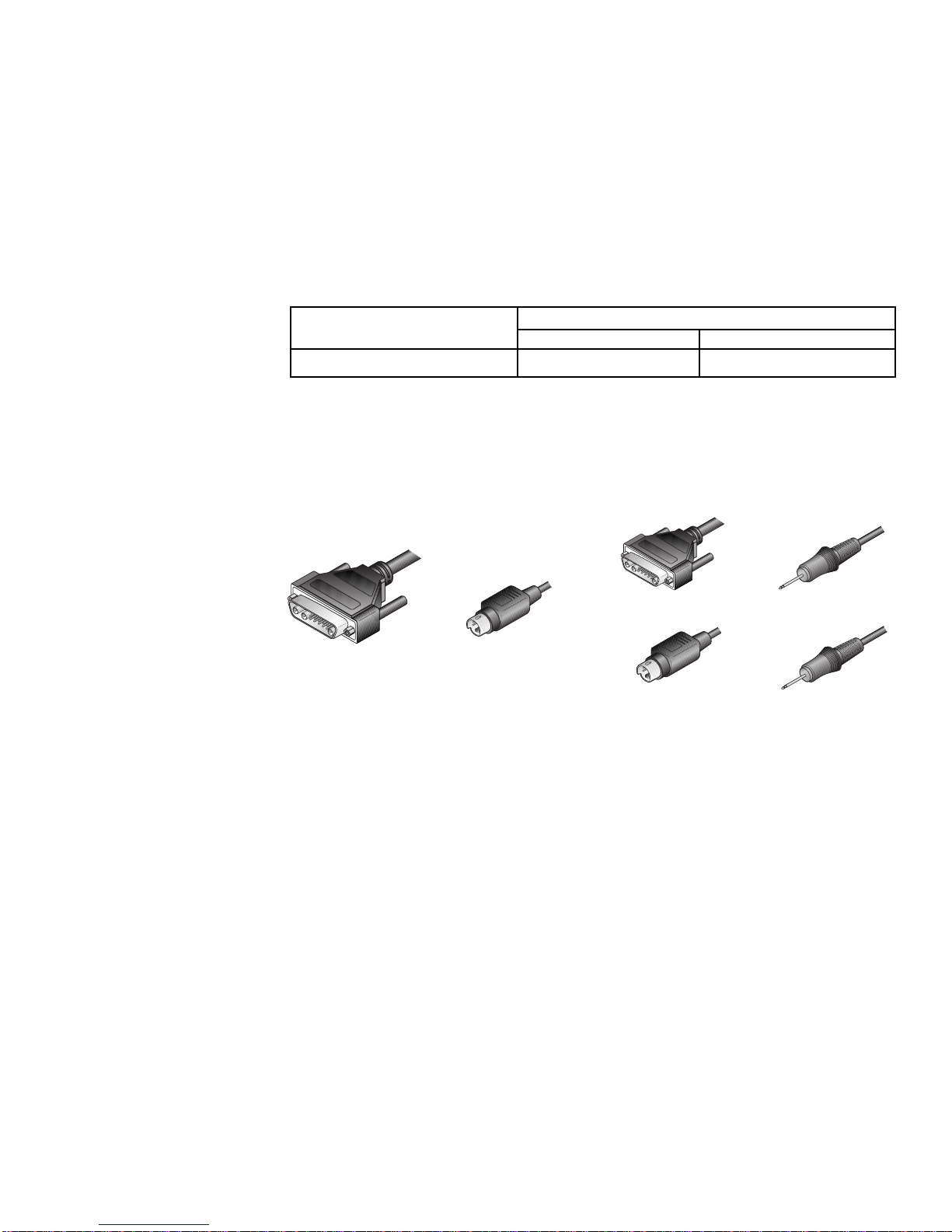
For IBM AT compatible computers with serial mouse capability
1. Your computer interface cables for this computer will be labeled either
CPUC-x or CPUF-x , depending on the options you ordered. Use the
cable diagrams below to locate the correct cable.
VGA VIDEO
KEYBOARDVGA VIDEO
SERIAL MOUSE
(yellow band)
SERIAL MOUSE
SERIAL PORT
KEYBOARD
MICROPHONE
(blue band)
SPEAKERS
CPUC-x CABLE CPUF-x CABLE
2. Power down your computer, then plug the cable's keyboard, serial
mouse and VGA monitor connectors into the matching ports on the PC.
If you have the CPUF-x series cable, you will have three additional
connectors: two 3.5mm connectors for a microphone and speakers, and
a 9-pin D-shaped serial connector for a serial port. The microphone
connector is denoted by a blue band around its cable; the serial mouse
connector is denoted by a yellow band. Plug these connectors into the
appropriate ports on your PC or peripheral device.
3. Attach the computer interface cable to the unit by plugging the 44-pin
connector into the rear of the appropriate computer interface module.
Ensure that the connector is firmly seated, then tighten the thumbscrews.
22
Page 29

For IBM PS/2 style computers with PS/2 mouse capability
1. Your computer interface cables for this computer will be labeled either
CPIC-x or CPIF-x , depending on the options you ordered. Use the cable
diagrams below to locate the correct cable.
VGA VIDEO
VGA VIDEO KEYBOARD
PS/2 MOUSE
(yellow band)
PS/2 MOUSE
(yellow band)
SERIAL PORT
KEYBOARD
MICROPHONE
(blue band)
SPEAKERS
CPIF-x CABLECPIC-x CABLE
2. Power down your computer, then plug the cable's keyboard, PS/2
mouse and VGA monitor connectors into the matching ports on the PC.
The mouse connector is denoted by a yellow band around its cable.
If you have the CPIF-x series cable, you will have three additional
connectors: two 3.5mm connectors for a microphone and speakers, and
a 9-pin D-shaped serial connector for a serial port. The microphone
connector is denoted by a blue band around its cable. Plug these connectors into the appropriate ports on your PC or peripheral device.
3. Attach the computer interface cable to the XP4000 Series unit by
For XPAB modules using the optional ReBoot xP
To attach your ReBoot xP to your XPAB computer interface module, see the
section “The ReBoot xP” in Chapter 11.
plugging the 44-pin connector into the rear of the appropriate computer
interface module. Ensure that the connector is firmly seated, then
tighten the thumbscrews.
23
Page 30
Attaching an
IBM RS/6000
Workstation
For RS/6000 Systems using standard VGA video
1. If your RS/6000 system utilizes standard VGA video, refer to the
previous section, “Attaching a PC Computer” and follow the instructions for configuring and installing your XPAC/XPAB modules, and
connecting computer interface cables for IBM PS/2 style computers.
For RS/6000 Systems using 13W3 video
1. If your RS/6000 system has a 13W3 video connector, refer to the
previous section, “Attaching a PC Computer” and follow the instructions for configuring and installing your XPAC/XPAB modules.
13W3 VIDEO CONNECTOR
2. In order to connect the computer interface cables, you will need a
VAD-21 adaptor from Cybex. If you do not have this adaptor, contact
our Sales Department to order one.
3. Follow the instructions for connecting computer interface cables for
IBM PS/2 style computers making sure to attach the VAD-15 between
the VGA video connector on your computer interface cables and your
RS/6000 workstation.
For RS/6000 Systems using 3C3 video
1. If your RS/6000 system has a 3C3 video connector, refer to the previous section, ‘Attaching a PC Computer’ and follow the instructions for
configuring and installing your XPAC/XPAB modules.
3C3 VIDEO CONNECTOR
2. Set the DIP switch on your XPAC/XPAB module as shown below:
Switch 1 Switch 2 Switch 3
Off Off Off Normal video. Use with monitors that
support sync on green.
Off Off On Use sync on green to generate horizontal
and vertical sync
3. In order to connect the computer interface cables, you will need a
VAD-18 adaptor from Cybex. If you do not have this adaptor, contact
our Sales Department to order one.
Function
24
Page 31

4. Follow the instructions for connecting computer interface cables for
IBM PS/2 style computers making sure to attach the VAD-18 between
the VGA video connector on your computer interface cables and your
RS/6000 workstation.
Attaching
a Silicon
Graphics
Workstation
For Indy or Indigo Systems
1. Refer to the section, “Attaching a PC Computer” and follow the instructions for configuring and installing your XPAC/XPAB modules.
2. Set the DIP switch on your XPAC/XPAB module as shown below:
Switch 1 Switch 2 Switch 3
Setting Setting Setting
Off Off Off Normal video. Use with monitors that
support sync on green.
Off Off On Use sync on green to generate horizontal
and vertical sync
3. In order to connect the computer interface cables, you will need a
VAD-15 adaptor from Cybex. If you do not have this adaptor, contact
our Sales Department to order one.
4. Follow the instructions for connecting computer interface cables for
IBM PS/2 style computers, making sure to attach the VAD-15 between
the VGA video connector on your computer interface cables and your
Silicon Graphics workstation.
Function
25
Page 32

Attaching a
Macintosh
Computer
XPAC module shown
Before you connect your Mac to an XP4000 Series system, you'll need to
configure and install your computer interface module. Both the XPAC and
XPAB modules have one set of jumpers and one DIP switch to configure. Follow
the steps below to configure each XPAC or XPAB module that will be connected
to a Macintosh computer.
Configuring your computer interface (XPAC/XPAB) modules
Configuring the Jumpers
The jumpers on the XPAC/XPAB module are used to control the video
selection settings. The default is IBM VGA/SVGA video.
DIP-SWITCH
ASSEMBLY
Orient your XPAC/XPAB module so that the 44-pin connector is to your right.
Locate the jumpers on the lower right corner of the board. The XPAC will
contain JP1 - JP6; the XPAB will only have jumpers JP1 - JP5. Configure your
XPAB module as you would an XPAC, ignoring all references to JP6. Use the
diagrams below to configure the video settings for the Macintosh computer
that you will attach to this computer interface module. You may wish to
consult your computer or video card reference manual for the video rates
supported by your computer.
3
1
2
1
2
3
4
5
6
*
STANDARD VGA (HS,VS)
APPLE
3
1
2
1
2
3
4
5
6
*
APPLE 21" APPLE PORTRAIT
3
1
2
1
2
3
4
5
6
*
*
STANDARD VGA (CS)
*
COLOR RGB (HS, VS)
*
APPLE 19" COLOR (CS)
44-PIN CONNECTOR
JUMPERS
1
2
1
2
3
4
5
6
1
2
1
2
3
4
5
6
APPLE
1
2
1
2
3
4
5
6
HS = horizontal sync, VS = vertical sync, CS = composite sync* XPAC Modules only
26
VIDEO
3
3
3
J1
J3
J5J6J4
J2
*
APPLE HIRES (HS, VS)APPLE
*
COLOR RGB (CS)
*
APPLE 16" COLOR
1
2
3
4
5
6
1
2
3
4
5
6
1
2
3
4
5
6
(HS,VS)
1
2
1
2
APPLE
1
2
J6
3
3
3
IBM VGA/SVGA
(default)
J4
J3
J5
J2
*
APPLE HIRES (CS)
*
*
APPLE 16" COLOR (CS)APPLE 19" COLOR (HS, VS)
J1
1
2
3
4
5
6
1
2
3
4
5
6
1
2
3
4
5
6
1
2
3
3
1
2
3
1
2
3
1
2
Page 33
Configuring the DIP Switch
The DIP switch is used to configure three different features: video options and
sync, keyboard/mouse time-out and keyboard translation options. The diagram
below shows the DIP switch, the positions used to configure each of these
features, and the default settings.
Keyboard/Mouse
Translation
Reserved
Video Options
If your monitor supports the type of sync generated by your Macintosh, no
configuration is required. If your monitor supports only horizontal and vertical
sync, locate the type of sync generated by your Mac in the table below and
configure your system accordingly.
By default, a computer's video will be displayed for any console user that switches
to that channel. If you do not want a computer's video to be displayed, you can
disable the video for that channel. Additionally, if you are only running your
keyboard and mouse through the XP4000 Series unit, and your video is independent
of the system, select the option to disable the video. See the table below.
Timeout
Video
7 8
Switch 1 Switch 2 Switch 3
Off Off Off Normal video (default)
On Off Off Strip sync on green
Off On Off Use composite sync to generate horizontal
and vertical sync
On On Off Use composite sync and strip sync on green
to generate horizontal and vertical sync
Off Off On Use sync on green to generate horizontal
and vertical sync
On On On Disable video
Function
Video Sync - XPAB only
Your XPAB card will attempt to automatically detect the sync for your
monitor. In some unique instances it will obtain the opposite of the settings.
Switching S7 to the on position will correct, this. See the table below.
Switch 7
Off Autodetect (default)
On Reverse Autodetected Sync
Sync Mode
Keyboard/Mouse Time-out
While multiple consoles can view a computer's video at once, only one station
has keyboard and mouse control at a time. The amount of time that a console's
keyboard and mouse must be inactive before another console can take control
is called the time-out. See the table below for the configurable time-outs.
Switch 4
Off 1 second (default)
On 10 seconds
27
Time
Page 34

Keyboard Translation Options
When using a PC keyboard to operate a Mac computer, the F11 key maps to the
Macintosh POWER key when Scroll Lock is on. By default, the F12 key maps
to the COMMAND key and the ALT key maps to the OPTION key. To use the
F12 key as the OPTION key and the ALT key as the COMMAND key, set switch
5 as shown below. With Scroll Lock off, F11, F12 and ALT function normally.
Switch 5
Translation Option
Setting
Off F12 maps to COMMAND, ALT maps to OPTION (default)
On F12 maps to OPTION, ALT maps to COMMAND
Note: Once your XPAC/XPAB module has been installed, you can change the
DIP switch setting at any time through a simple hot-key sequence. See Chapter
9, Advanced Operations, for more information.
Installing the XPAC/XPAB modules
1. Position the XP4000 Series unit so that the rear panel is facing you.
Choose an available slot. An available slot will have a solid panel
covering the opening, with no connectors showing through it.
NOTE: For Front Access models, the LCI module, at the far left of the
unit (viewed from rear), is covered by a solid panel but IS NOT an
available slot.
LCI MODULE (FRONT ACCESS MODEL ONLY)
LCI MODULE (FRONT ACCESS MODEL ONLY)
AVAILABLE SLOTS FOR OPERATION MODULES
AVAILABLE SLOTS FOR OPERATION MODULES
AC INPUT
90-240 VAC, 47-63 Hz
1 AMP FAST BLOW
250 VAC
2. Remove the panel covering the available slot by unscrewing the two
Phillips-head screws on the rear of the unit that hold the panel in place.
3. Slide the new computer interface module gently into the open slot
until the 44-pin connector lines up flush with the back of the unit.
4. Retighten the holding screws completely. DO NOT overtighten.
5. Fill out the XPAC/XPAB Configuration Chart in Appendix A for each
module as you install it.
Follow this procedure for every computer interface module in your system.
28
Page 35

Connecting the Computer Interface Cables
Computer interface cables connect your computers to the XP4000 Series unit.
You will have a set for each computer in your XP4000 system. These cables
are a user specified length with a 44-pin D-shaped female connector on one
end. The other end will have from 2 to 8 connectors, depending on the cable
you ordered and the kind of computer you are attaching. The table below
shows the cables that are compatible with your Macintosh computer. Use the
instructions below that apply to the cable type you are using, and repeat the
process for each additional Macintosh computer in your system.
Computer Computer interface cables
Standard Multimedia
Macintosh CPAC-x CPAF-x
Replace x with the distance cable you ordered.
For Macintosh computers
1. Your computer interface cables for this computer will be labeled either
CPAC-x or CPAF-x , depending on the options you ordered. Use the
cable diagrams below to locate the correct cable.
VIDEO MICROPHONE
VIDEO
CPAC-x CABLE CPAF-x CABLE
ADB
ADB
(blue band)
SPEAKERS
2. Power down your computer, then plug the cable's keyboard/mouse
(ADB) and monitor connectors into the matching ports on the Mac.
If you have the CPAF-x series cable, you will have two additional
connectors: two 3.5mm connectors for a microphone and speakers. The
microphone connector is denoted by a blue band around its cable. Plug
these connectors into the appropriate ports on your Macintosh or peripheral device.
3. Attach the computer interface cable to the XP4000 Series unit by
plugging the 44-pin connector into the rear of the appropriate computer
interface module. Ensure that the connector is firmly seated, then
tighten the thumbscrews.
For XPAB modules using the optional ReBoot xP
To attach your ReBoot xP to your XPAB computer interface module, see the
section “The ReBoot xP” in Chapter 11.
29
Page 36

J5
J6
J4
J2
J3
J1
2
3
1
Attaching
a Sun
Workstation
Before you connect your Sun to the XP4000 Series unit, you will need to
configure and install your computer interface module. Both the XPAC and
XPAB modules have one set of jumpers and one DIP switch to configure.
Follow the steps below to configure each XPAC or XPAB module that will be
connected to a Sun workstation.
Configuring your computer interface (XPAC/XPAB) modules
Configuring the Jumpers
The jumpers on the XPAC/XPAB module are used to control the video
selection settings. The default is IBM VGA/SVGA video.
XPAC module shown
DIP-SWITCH
ASSEMBLY
44-PIN CONNECTOR
J1
J3
J5J6J4
J2
VIDEO
JUMPERS
IBM VGA/SVGA
(default)
Orient your XPAC/XPAB module so that the 44-pin connector is to your right.
Locate the jumpers on the lower right corner of the board. The XPAC will
contain JP1 - JP6; the XPAB will only have jumpers JP1 - JP5. Configure your
XPAB module as you would an XPAC, ignoring all references to JP6. Use the
diagrams below to configure the video settings for the Sun workstation that
you will attach to this computer interface module. You may wish to consult
your computer or video card reference manual for the video rates supported by
your computer.
3
1
2
1
2
3
4
5
6
*
SUN
1152 x 900 @66 Hz
*
1152 x 900 @76 Hz
3
1
2
1
2
3
4
5
6
SUN
*
1152 x 900 @76 Hz
3
1
2
1
2
3
4
5
6
SUN
* XPAC Modules only
3
1
2
1
2
3
4
5
6
*
SUN
1280 x 1024 @76 Hz
30
3
1
2
1
2
3
4
5
6
*
SUN
1600 x 1280 @76 Hz
Page 37

Configuring the DIP Switch
The DIP switch is used to configure three different features: video options and
sync, keyboard/mouse time-out, and keyboard translation options. The diagram
below shows the DIP switch, the positions used to configure each of these
features, and the default settings.
Keyboard/Mouse
Translation
Reserved
Timeout
Video
7 8
Video Options
If your Sun uses composite sync and your monitor will support this, no
additional configuration is required. If your monitor requires horizontal and
vertical sync, configure your system according to the table below.
By default, a computer's video will be displayed for any console user that
switches to that channel. If you do not want a computer's video to be displayed,
you can disable the video for that channel. Additionally, if you are only
running your keyboard and mouse through the XP4000 Series unit, and your
video is independent of the system, you should select the option to disable the
video. See the table below.
Switch 1 Switch 2 Switch 3
Function
Setting Setting Setting
Off Off Off Normal video (default)
Off On Off Use composite sync to generate horizontal
On On On Disable video
and vertical sync
Video Sync - XPAB only
Your XPAB card will attempt to automatically detect the sync for your
monitor. In some unique instances it will obtain the opposite of the settings.
Switching S7 to the on position will correct, this. See the table below.
Switch 7
Off Autodetect (default)
On Reverse Autodetected Sync
Sync Mode
31
Page 38

Keyboard/Mouse Time-out
While multiple consoles can view a computer's video at the same time, only
one station can have keyboard and mouse control at a time. The amount of time
that a console's keyboard and mouse must be inactive before another console
can take control is called the time-out. See the table below for the available
time-outs that can be configured.
Switch 4
Time
Setting
Off 1 second (default)
On 10 seconds
Note: Once your XPAC/XPAB module has been installed, you can change the
DIP switch setting at any time through a simple hot-key sequence. See
Chapter 9, Advanced Operations for more information.
Installing the XPAC/XPAB modules
1. Position the XP4000 Series unit so that the rear panel is facing you. Choose
an available slot. An available slot will have a solid panel covering the
opening, with no connectors showing through it.
NOTE: For front access models, the LCI module, at the far left of the unit
(viewed from rear), is covered by a solid panel but IS NOT an available
slot. Only the LCI module is installed in this slot.
LCI MODULE (FRONT ACCESS MODEL ONLY)
LCI MODULE (FRONT ACCESS MODEL ONLY)
AVAILABLE SLOTS FOR OPERATION MODULES
AVAILABLE SLOTS FOR OPERATION MODULES
AC INPUT
90-240 VAC, 47-63 Hz
1 AMP FAST BLOW
250 VAC
2. Remove the panel covering the available slot by unscrewing the two
Phillips-head screws on the rear of the unit that hold the panel in place.
3. Slide the new computer interface module gently into the open slot until the
44-pin connector lines up flush with the back of the unit.
4. Retighten the holding screws completely. DO NOT overtighten.
5. Fill out the XPAC/XPAB Configuration Chart in Appendix A for each
module as you install it.
Follow this procedure for every computer interface module in your system.
32
Page 39
Connecting the Computer Interface Cables
Computer interface cables connect your computers to the XP4000 Series unit.
You will have a set for each computer in your XP4000 system. These cables are
a user specified length with a 44-pin D-shaped female connector on one end.
The other end will have from 2 to 8 connectors, depending on the cable you
ordered and the kind of computer you are attaching. The table below shows the
cables that are compatible with your Sun workstation. Use the instructions
below that apply to the cable type you are using, and repeat the process for each
additional Sun in your XP4000 system.
Computer Computer interface cables
Standard Multimedia
Sun Workstation/Server CWSC-x CWSF-x
Replace x with the distance cable you ordered.
For Sun workstation/servers
1. Your computer interface cables for this computer will be labeled either CWSCx or CWSF-x , depending on the options you ordered. Use the cable
diagrams below to locate the correct cable.
VIDEO
VIDEO
CWSC-x CABLE CWSF-x CABLE
KEYBOARD/
MOUSE
KEYBOARD/MOUSE
MICROPHONE
(blue band)
SPEAKERS
2. Power down your computer by performing a shutdown from the keyboard.
Then plug the computer interface cable's keyboard/mouse and monitor
connectors into the matching ports on the Sun.
If you have the CWSF-x series cable, you will have two additional
connectors: two 3.5mm connectors for a microphone and speakers. The
microphone connector is denoted by a blue band around its cable. Plug
these connectors into the appropriate ports on your Sun or peripheral
device.
3. Attach the computer interface cable to the XP4000 Series unit by plugging
the 44-pin connector into the rear of the appropriate computer interface
module. Ensure that the connector is firmly seated, then tighten the
thumbscrews.
For XPAB modules using the optional ReBoot xP
To attach your ReBoot xP to your XPAB computer interface module, see the
section “The ReBoot xP” in Chapter 11.
33
Page 40

Attaching a
HewlettPackard
Workstation
Some older Hewlett-Packard workstations use an HIL interface for the keyboard
and mouse. If your system uses HIL and you do not have an HIL to PS/2
adaptor, you may purchase one by contacting:
Modular Industrial Computers
6025 Lee Highway Suite 140
Chattanooga, TN 37421
Part # HIL-100
Phone (423) 499-0700 Fax (423) 892-0000
Before you connect your HP Workstation to the XP4000 Series unit, you will
need to configure and install your computer interface module. Both the XPAC
and XPAB modules have one set of jumpers and one DIP switch to configure.
Follow the steps below to configure each XPAC or XPAB module that will be
connected to an HP Workstation.
Configuring your computer interface (XPAC/XPAB) modules
Configuring the Jumpers
The jumpers on the XPAC/XPAB module are used to control the video
selection settings. The default is IBM VGA/SVGA video. If your XPAC/
XPAB module is not already set for the default, orient the board so that the 44pin connector is to your right. Locate the jumpers on the lower right hand
corner of the board. The XPAC will contain JP1 - JP6; the XPAB will only
have jumpers JP1 - JP5. Configure your XPAB module as you would an XPAC,
ignoring all references to JP6. Set your jumpers to the default as shown below,
and proceed to the DIP switch settings.
XPAC module shown
DIP-SWITCH
ASSEMBLY
44-PIN CONNECTOR
J1
J3
J5J6J4
J2
VIDEO
JUMPERS
IBM VGA/SVGA
(default)
J4
J3
J5
J6
*
* JP6 in XPAC Modules only
J2
J1
1
2
3
34
Page 41
Configuring the DIP Switch
The DIP switch is used to configure three different features: video options and
sync, keyboard/mouse time-out, and keyboard translation options. The diagram
below shows the DIP switch, the positions used to configure each of these
features, and the default settings.
Keyboard/Mouse
Translation
Reserved
Timeout
Video
7 8
Video Options
Your XP4000 Series system is factory set for VGA video. No changes are
needed to switches 1 through 3 for normal VGA video. Similarly, if your HP
uses BNC video and your monitor supports sync on green, no changes are
required. However, if your HP uses BNC video and your monitor supports
horizontal and vertical sync only, configure your system according to the table
below.
By default, a computer's video will be displayed for any console user that
switches to that channel. If you do not want a computer's video to be displayed,
you can disable the video for that channel. Additionally, if you are only
running your keyboard and mouse through the XP4000 Series unit, and your
video is independent of the system, you should select the option to disable the
video. See the table below.
Switch 1 Switch 2 Switch 3
Function
Setting Setting Setting
Off Off Off Normal video (default)
On On On Video disabled
Off Off On Use sync on green to generate horizontal
and vertical sync
Keyboard/Mouse Time-out
While multiple consoles can view a computer's video at the same time, only
one station can have keyboard and mouse control at a time. The amount of time
that a console's keyboard and mouse must be inactive before another console
can take control is called the time-out. See the table below for the available
time-outs that can be configured.
Switch 4
Time
Setting
Note: Once your XPAC/XPAB module has been installed, you can change the
Off 1 second (default)
On 10 seconds
DIP switch setting at any time through a simple hot-key sequence. See
Chapter 9, Advanced Operations for more information.
35
Page 42

Installing the XPAC/XPAB modules
1. Position the XP4000 Series unit so that the rear panel is facing you. Choose
an available slot. An available slot will have a solid panel covering the
opening, with no connectors showing through it.
NOTE: For front access models, the LCI module, at the far left of the unit
(viewed from rear), is covered by a solid panel but IS NOT an available
slot. Only the LCI module can be installed in this slot.
LCI MODULE (FRONT ACCESS MODEL ONLY)
LCI MODULE (FRONT ACCESS MODEL ONLY)
AVAILABLE SLOTS FOR OPERATION MODULES
AVAILABLE SLOTS FOR OPERATION MODULES
AC INPUT
90-240 VAC, 47-63 Hz
1 AMP FAST BLOW
250 VAC
2. Remove the panel covering the available slot by unscrewing the two
Phillips-head screws on the rear of the unit that hold the panel in place.
3. Slide the new computer interface module gently into the open slot of the
XP4000 Series unit until the 44-pin connector lines up flush with the back
of the unit. See the diagram below.
4. Retighten the holding screws completely. DO NOT overtighten.
5. Fill out the XPAC/XPAB Configuration Chart in Appendix A for each
module as you install it.
Follow this procedure for every computer interface module in your system.
36
Page 43
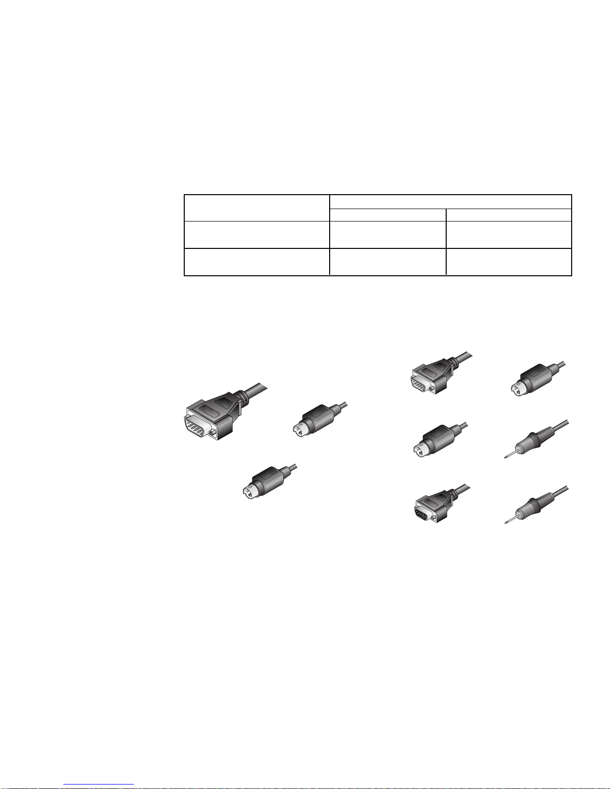
Connecting the Computer Interface Cables
Computer interface cables connect your computers to the XP4000 Series unit.
You will have a set for each computer in your XP4000 system. These cables
are a user specified length with a 44-pin D-shaped female connector on one
end. The other end will have from 2 to 8 connectors, depending on the cable
you ordered and the kind of video connector on your workstation. The table
below shows the cables that are compatible with your HP workstation. Use the
instructions on the following pages that apply to the cable you are attaching,
and repeat the process for each additional HP workstation in your XP4000
Series system.
Computer Computer interface cables
Standard Multimedia
HP Workstation with a CPIC-x CPIF-x
VGA video connector
HP Workstation with CWI3C-x CWI3F-x
BNC video connectors
Replace x with the distance cable you ordered.
For HP Workstations with a VGA Video Connector
1. Your computer interface cables for this computer will be labeled either
CPIC-x or CPIF-x, depending on the options you ordered. Use the cable
diagrams below to locate the correct cable.
VGA VIDEO
VGA VIDEO KEYBOARD
PS/2 MOUSE
(yellow band)
PS/2 MOUSE
(yellow band)
SERIAL PORT
KEYBOARD
MICROPHONE
(blue band)
SPEAKERS
CPIC-x CABLE CPIF-x CABLE
2. Power down your computer, then plug the cable's keyboard, PS/2 mouse
and VGA monitor connectors into the matching ports on the workstation.
The mouse connector is denoted by a yellow band around its cable.
If you have the CPIF-x series cable, you will have three additional
connectors: two 3.5mm connectors for a microphone and speakers, and a
9-pin D-shaped serial connector for a serial port. The microphone connector
is denoted by a blue band around its cable. Plug these connectors into the
appropriate ports on your workstation or peripheral device.
3. Attach the computer interface cable to the XP4000 Series unit by plugging the
44-pin connector into the rear of the appropriate computer interface module.
Ensure that the connector is firmly seated, then tighten the thumbscrews.
37
Page 44

For HP Workstations with BNC Video Connectors
1. Your computer interface cables for this computer will be labeled either
CWI3C-x or CWI3F-x, depending on the options you ordered. Use the
cable diagrams below to locate the correct cable.
BNC VIDEO KEYBOARD
BNC VIDEO
PS/2 MOUSE
(yellow band)
KEYBOARD
PS/2 MOUSE
(yellow band)
SERIAL PORT
MICROPHONE
(blue band)
SPEAKERS
CWI3F-x CABLECWI3C-x CABLE
2. Power down your computer, then plug the cable's keyboard, PS/2 mouse
and BNC video connectors into the matching ports on the workstation. The
mouse connector is denoted by a yellow band around its cable.
If you have the CWI3F-x series cable, you will have three additional
connectors: two 3.5mm connectors for a microphone and speakers, and a
9-pin D-shaped serial connector for a serial port. The microphone connector
is denoted by a blue band around its cable. Plug these connectors into the
appropriate ports on your workstation or peripheral device.
3. Attach the computer interface cable to the XP4000 Series unit by plugging
the 44-pin connector into the rear of the appropriate computer interface
module. Ensure that the connector is firmly seated, then tighten the
thumbscrews.
For XPAB modules using the optional ReBoot xP
To attach your ReBoot xP to your XPAB computer interface module, see the
section “The ReBoot xP” in Chapter 11.
38
Page 45

4
Attaching Terminals
Overview
Overview of the XPIQ
and XPSI modules
On-screen menus for
naming, selecting and
configuring terminals
On-board microprocessor allows Security
Monitoring and System
Management Tools
FLASH upgradeable
plug-in modules
The XPIQ and XPSI modules work together to enable you to connect terminalbased file servers, network hubs, routers and other serial based server room
equipment to your XP4000 Series unit and control them using one keyboard,
monitor and mouse. This "terminal switching" requires at least one XPIQ and
one XPSI module in the system. The XPIQ module provides the menuing and
advanced control features; XPSI modules provide four ports each for attaching
equipment to your XP4000 system. From your XPIQ module, you may select
any terminal in the system, regardless of which of the 4-port XPSI modules it
is attached to.
The XPIQ module functions similarly to an XPAC/XPAB computer interface
module in that you switch directly to it from your keyboard, on-screen menus
or front panel push-buttons, if applicable. Once you have switched to the XPIQ,
on-screen menus allow you to name and select the attached terminals in your
XP4000 system. You can also configure baud rate, data bits, stop bits, parity
and flow control for each terminal through the menus.
The XPIQ module contains an on-board microprocessor that enables the
Security Monitoring System and the System Management Tools. The Security
Monitoring System allows administrators to track all switching activity
through a simple on-screen menu. Immediate feedback on logging and
switching history is available for every system user. The System Management
Tools allow network managers to display their XP4000 system configurations
for easy troubleshooting. This menu-driven system shows the type of module
installed in each port and the current firmware and hardware revision of each.
Information on the type of computer attached to each computer interface
module is also available.
The XPIQ and XPSI modules are field installable and FLASH upgradeable.
Modules can be added or replaced without disassembling or powering down the
system. This makes installation, configuration and maintenance much easier.
39
Page 46

Installing the
XPIQ and XPSI
Modules
1. Position the XP4000 Series unit so that the rear panel is facing you. Choose
an available slot. An available slot will have a solid panel covering the
opening to the unit, with no connectors showing through it.
NOTE: For Front Access models, the LCI module, located to the far left of
the unit (viewed from rear), is covered by a solid panel but IS NOT an
available slot. Only the LCI module can be installed in this slot.
2. Remove the panel covering the available slot by unscrewing the two
Phillips-head screws on the rear of the unit that hold the panel in place.
3. Slide the new module gently into the open slot of the XP4000 Series unit
until the connector(s) line up flush with the back of the unit. See the
diagram below.
Attaching
Terminals to
the XPSI
Module
4. Retighten the holding screws completely. DO NOT overtighten.
Follow the above procedure for every XPIQ and XPSI module in your system.
The XPSI module has four ports available for attaching terminals, hubs, routers
and other serial-based equipment. To attach this equipment to the XP4000
system, follow the steps outlined below.
1. You will need a Category 5 UTP cable to connect your XPSI to your
equipment. Cybex provides these cables, with an RJ45 connector on each
end, in lengths from 10 to 150 feet. (C5T-10, C5T-25, C5T-50, C5T-100,
C5T-150). We recommend using Cybex cables in your XP4000 configuration.
2. Plug one end of your Cat 5 cable into the first available port on the rear of
your XPSI module.
3. Depending on the type of equipment you are attaching to the XPSI, you will
need an adaptor to attach to the remaining end of the Cat 5 cable. A list of
common adaptors and their Cybex part number is shown on the following
page. Select the adaptor that meets your requirements.
4. After attaching the appropriate adaptor, connect the remaining end of the
Cat 5 cable to the equipment you wish to attach to the XP4000 system.
40
Page 47

Functionality with
Part Number Description C5T cable
SAD-5 RJ45 to DB9 male DCE
SAD-6 RJ45 to DB9 male DTE
SAD-7 RJ45 to DB9 female DCE
SAD-8 RJ45 to DB9 female DTE
SAD-9 RJ45 to DB25 male DCE
SAD-10 RJ45 to DB25 male DTE
SAD-11 RJ45 to DB25 female DCE
SAD-12 RJ45 to DB25 female DTE
SAD-13 6-pin mini-DIN male to DB9 female (for use with HP9000 machines)
C5T cable wiring is straight through. (i.e. Pin 1 goes to Pin 1, Pin 8 to Pin 8)
Addressing
Terminals on
the XPSI
Module
Getting Started
Since each XPSI module has four ports, channel addressing requires more than
just a chassis number and slot letter. You must also designate which port on
the XPSI the terminal is attached to. Ports are numbered from top to bottom as
shown below.
1
2
3
4
For example, the terminal attached to the second port on the XPSI in slot D of
chassis 15 would be addressed 15D2.
When you first power up your XPIQ module, the following Options Screen
appears on your monitor:
User Options
---------------------------------------
ALT-M
Use this command to enter the menuing system. The first menu to appear will
be the Channel or Terminal List.
ALT-M to view the Terminal List
ALT-O to open a Terminal Session
ALT-N to view the Security Monitor
ALT-T to view the System Management Tools
ALT-C to close a view
ALT-I to view Information
ALT-B to emulate VT100 BREAK key
ALT-Tab to change to another view
41
Page 48

ALT-O
When you select a device attached to an XPSI module, it is called opening a
session. You may use the Alt-O command to open a session from anywhere in
the menuing program. Sessions may also be opened through the Open Session
Menu, discussed later in this chapter.
ALT-N
Alt-N brings up the Security Monitor. This is used to track the logging and
switching history of system users. The Security Monitor can also be accessed
through the Administrator Control Menu, discussed later in this chapter.
ALT-T
Alt-T brings up the System Management Tools. These tools are used for
system maintenance and troubleshooting. The System Management Tools can
also be accessed through the Administrator Control Menu, discussed later in
this chapter.
ALT-C
Alt-C is used to close the active, or current, channel. Once you close a session,
the Options Screen will appear until you select another channel as active. This
is the only method available for closing a session. For more information on
opening and closing a session, see the Open Session Menu discussed later in
this chapter.
ALT-I
This command displays the current channel address, EPROM date and the
hardware, firmware and FLASH revision dates of your XPIQ module. Press
any key to exit this information window.
ALT-B
This command is used to emulate the BREAK key found on many ASCII
terminals. Its function is user dependent.
ALT-Tab
After you press ALT-M to initiate your menuing system, Alt-Tab is used to cycle
through the three available system menus. Alt-Tab is also used to cycle through
your open sessions. The Open Session Menu is discussed later in this chapter.
42
Page 49

On-Screen
Menu Overview
The XPIQ module's on-screen display is made up of three main menus:
Channel List Menu
Administrator Control Menu
Open Session Menu
To access the Channel List Menu, press Alt-M. Press Alt-tab to cycle through
the remaining menus.
The Channel List Menu
This menu displays the name and address of each server. The gray bar at the
bottom lists all options available from this menu. Use the F11 key to scroll
through these options. See the table below.
Key Sequence Action
F1 Press the F1 key for context sensitive help.
F3 Press F3 for the port settings to configure your channel.
Baud rates: 19200, 9600, 4800, 2400, 1200
Data bits: 7 or 8
Stop bits: 1 or 2
Parity: None, Even or Odd
Flow control: None, Xon/Xoff, or RTS/CTS
Press enter when configuration has been completed.
Enter Press enter to switch to the highlighted channel.
F11 Press F11 to see more available options.
F4 Press F4 for a quick edit of the selected channel name or address.
Alt-Tab Press Alt-Tab to cycle through the available menus.
Delete Press delete to remove the selected channel.
Insert Press the Insert key to add a new channel to your menu.
F2 Press F2 to bring up the channel set-up menu. From here you
can configure the selected channel's name and address.
(-) Press the keypad (-) key to sort the Channel List by address.
Brackets <> around the Address heading will confirm that the
sort method is active.
(+) Press the keypad (+) key to sort the Channel List by name.
Brackets <> around the Name heading will confirm that the sort
method is active.
43
Page 50

Searching the Channel List
Channel searching will be based on the sort order. If you are currently sorting
by Name, a search will be performed on the Name field. If Address is the current
sort field, a search will be performed on the system addresses.
To search, bring up the Channel List Menu and enable the sort method of your
choice. Next enter the first letter or number you wish to sort on. The next key
you press will add the second letter or number to your search string, and so on.
For example, if sorting by name, entering “M” will move your cursor to all
entries that begin with the letter M. Enter “A” and your cursor moves to entries
beginning with MA. Continue until you reach your desired entry.
The Administrator Control Menu
This menu contains two options for maintenance and troubeshooting: System
Management Tools and System Security Monitor. The System Management
Tools option contains six items. You can display information on the type and
revision of each module and the Flash ROM status of any applicable system
module. You can Flash upgrade your XPIQ modules as well as set the module's
date and time, reboot computers and search your system for connected units. For
more details, see "Using System Management Tools" in this chapter.
Selecting the System Security Monitor option brings up a three part window on
your monitor. From here, you can track the logging and switching history for
every system user. Active system users are listed as well as their current
selected channel. If any unauthorized activity occurs, an alert screen lists the
date, time, user and specific action. For more details, see "Using the Security
Monitor" in this chapter.
The Open Session Menu
What is Opening a Session?
When you select a device attached to an XPSI module, it is called opening a
session. The selected channel's video appears on your monitor and the channel
name is displayed in the lower right hand corner. If you open a second channel,
this new channel becomes current. The new channel name replaces the first
channel in the righthand corner, and the older channel name is displayed in one
of the three remaining blocks at the bottom of the menu. See below.
Workstation Router Network Hub XP Moniter 0, 0
Open Channels
Line 1 of 2
Open Channel List
44
1/1
Active Channel
Cursor
position
Page 51

Every time you open a new channel, or session, the most current channel will
appear in the right corner and the remaining open sessions will be listed in the
scrollable text blocks in the left corner. You may have up to eight sessions
open at a time. To cycle through your open sessions, press Alt-tab.
Opening a Session
There are two ways to open a session. The first way is to bring up your Channel
List by pressing Alt-M, selecting the channel from the menu, and pressing
enter. The second way is by using the Open Session Menu.
To use the menu, channel switch to the port that contains your XPIQ module.
Press Alt-O to bring up the Open Session Menu. Type in the address of the
channel you wish to open a session for and press enter. To leave the menu
without opening a session, press escape.
Closing a Session
To close a session, make the channel that you want to close the active, or
current, channel. You may do this by pressing Alt-tab until the session you
want to close is displayed on your monitor. Then, press Alt-C. The session will
close and the Options Screen will be displayed until you select another channel
as active.
45
Page 52

Using System
Management
Tools
Once you have cycled to the Administrator Control Menu with Alt-Tab,
choose the System Management Tools option. You may also use the keyboard
shortcut Alt-T from anywhere within the XPIQ module. The menu below will
appear on your monitor. An explanation of each option follows.
System Management Tools
Main Menu
1) Display chassis configuration
2) Display Flash ROM status
3) Download Serial Port to Flash ROM
4) Reboot computer
5) Search for connected chassis
6) Set Date and Time
7) Transfer security log
Enter your selection:
Displaying Local/Remote Chassis Configurations
Choosing Option 1 from the main menu will bring up the table shown below,
displaying your XP4000 system's current configuration information. You will
be prompted for a chassis number, or address, before the table is displayed.
Enter a remote chassis address or press enter at the prompt for the local unit.
Note that the slot without a push-button or LED is designated by “M” and the
primary peripheral workstation, or the LCI, channel is designated by “N”.
Chan Card Type HW Rev FW Rev FW Rev Serial # Other Information
---- --------- ------ ------ ------ ----------- ---------------- 3-A Empty
3-B XPAC B03 * D-00 -NA- 0123456789 PC + PS/2 mouse
3-C XPAC C00 * D-00 -NA- 0123456789 No cable attached
3-D Empty
3-E Empty
3-F Empty
3-G Empty
3-H Empty
3-I XPXT A00 * C-04 -NA- 0123456789
3-J XPXT A00 * C-04 -NA- 0123456789
3-K Empty
3-L Empty
3-M XPRB A00 * C-06 CMON 0123456789
3-N Empty
* - Indicates active device.
EPROM FLASH
Module type
Hardware revision
Upgrade firmware revision
Standard firmware revision
P1[N/C] P2 [ 4-F]
P1[N/C] P2 [ 5-F]
Channel position
46
Page 53

Displaying Local/Remote Flash ROM Status
When you choose Option 2 from the main menu, you will be prompted to enter
a channel address. Enter a remote address or leave the field blank for the local
channel. The module's firmware and current revision level will be displayed.
Downloading Serial Port to Flash ROM
Option 3 allows you to transfer firmware upgrades from your computer,
through the serial port, to your local XPIQ module's Flash storage.
Download Serial Port to Flash ROM
Start XMODEM download now
Rebooting a Computer
If you have a ReBoot xP in your system, Option 5 allows you to reset attached
computers through the menuing system.
Reboot computer
Channel address: 3C
Power Port number: 1
Enter the address of the channel you wish to reset. If the channel is an XPRB
module, you will also need to give the position number of the Power Port on
the XPRB. See below. If the channel is an XPAB module, accept the default
value of “1”.
1
2
3
4
5
6
Searching for Connected Chassis
Choose Option 5 to search your XP4000 system for all connected chassis.
Search for connected chassis
First chassis number [1]:
Last chassis number [25]:
You will be prompted for the range of chassis numbers you want to search.
Enter the first and last chassis numbers for your search or press enter to accept
the default values of 1 and 25. After you have entered values, the connected
chassis in the selected range will be listed on the screen.
47
Page 54

Setting the Date and Time
Choose Option 6 to set the date and time for your XPIQ module. This is used
to time stamp the events in the security log.
Transferring the Security Log
Choose Option 7 to transmit the contents of the security log via the XPIQ’s
serial interface port. Using a personal computer and a suitable terminal
emulation program, the security log can be captured to a file for printing and
storing. Procomm and HyperTerminal are examples of terminal emulation
programs that can capture the log from the XPIQ.
Connecting the XPIQ to a Computer
You will need to connect the XPIQ module's serial interface to a laptop
computer to transfer the security log. The following Cybex cable components
are required for this operation:
1 SAD-7 serial adaptor
1 SAD-8 serial adaptor
1 C5T-10, C5T-25 ... (Category 5 cable)
Install a serial adaptor on each end of the category 5 cable. Connect one serial
adaptor to the laptop computer and the other to the XPIQ module. It does not
matter which adaptor goes to the XPIQ and which goes to the computer.
Transferring the Data
The data will be formatted the same as the XPIQ Security Monitor’s log
window. Each line of ASCII text ends with carriage return and line feed codes.
The COMM port used by the PC’s terminal emulation program must be
configured to match the settings you select with this option. Either accept the
default port settings or enter different values. Enter or accept the date and time
of the first log record you want to transfer. See below.
Transfer security log
Configure serial port
Press SPACE to change, ENTER to accept.
Baud rate: 9600
Data bits: 8
Stop bits: 1
Parity : None
Flow Control: Xon/Xoff
Date of first log record [ Jun-05-1998 ]:
Time of first log record [ 15:59:41 ]:
Transferring Security Event Log Records
that have occurred since: Jun-05-1998 15:59:41
After the transfer is complete, press any key to return to the System Management
Tools Main Menu.
48
Page 55

Using the
Security
Monitor
Once you have cycled to the Administrator Control Menu with Alt-Tab,
choose the System Security Monitor option. You may also use the keyboard
shortcut Alt-N from anywhere within the XPIQ module. The screen shown
below will appear on your monitor.
Alert Message
Active User List
Chan Username Selected Chan
1-L John 1-B
2-K Gene 2-B
1-C Kyle 1-J
1-D Administrator 4-A
1-L Administrator 3-B
Log Window
Time & Date ALERT Source Description
May-14-98 11:28:00 3C Select: Username: “John ” channel: 1-B
May-14-98 11:34:54 3C Select: Username: “Jene ” channel: 2-B
May-14-98 11:43:13 3C Select: Username: “Administrator” channel: 3-B
May-14-98 11:54:34 3C Select: Username: “Kyle ” channel: 1-J
May-14-98 12:04:45 3C Select: Username: “John ” channel: 1-B
May-14-98 12:08:14 3C Select: Username: “Administrator” channel: 4-A
May-14-98 12:28:20 3C Select: Username: “Jene” channel: 1-B
TAB- select next window SPACE- clear alerts
Workstation Router Network Hub XP Moniter 0, 0
Alert Message
May-14-98 11:28:00 Src: 1L LOGIN FAILED: INVALID PASSWORD
May-14-98 11:28:00 Src: 1L LOGIN FAILED: INVALID PASSWORD
Username: “Administrator”
Username: “Administrator”
May-18-98 15:42:25 Src: 2-K ACCESS DENIED: INVALID PASSWORD
May-18-98 15:42:25 Src: 2-K ACCESS DENIED: INVALID PASSWORD
Username: “Administrator”
Username: “Administrator”
1/1
The Security Monitoring screen is a three part window, featuring the Active
User List, the Alert Messages Window and the Log Window. Press the Tab key
to select the active window. Available options for the active window will
appear at the bottom of the screen. Each window is described below.
The Active User List
The Active User List shows which users are currently logged on and what
channel they are switched to. The user's address and name are listed as well as
their selected computer channel. You have the option of paging up to the
previous page of users, paging down to the next page, returning to the top of
the list or to the end.
Active User List
Chan Username Selected Chan
1-L John 1-B
2-K Gene 2-B
1-C Kyle 1-J
1-D Administrator 4-A
1-L Administrator 3-B
49
Page 56

The Alert Message Window
The Alert Message Window lists any failed or unauthorized command and
turns the window red to alert administrators to the message. Pressing the space
bar clears the alert by removing the red background. The message itself
remains on-screen until the window is full, then is replaced by newer messages.
The date, time, user name and channel and the unauthorized activity are listed
for each message.
Alert Message
May-14-98 11:28:00 Src: 1L LOGIN FAILED: INVALID PASSWORD
May-18-98 15:42:25 Src: 2-K ACCESS DENIED: INVALID PASSWORD
Username: “Administrator”
Username: “Administrator”
The Log Window
The Log Window tracks all logging and switching activity for every system
user. The date, time, user name and channel and activity are listed. You have
the option of paging up to the previous page of history, paging down to the next
page, returning to the top of the log or to the end. An asterisk (*) in the ALERT
field indicates that the command generated an entry in the Alert Message
Window. See above.
Information from the Log Window can be downloaded through your computer's
serial port for printing and storing. See the section "Using System Management
Tools" in this chapter for more details.
Log Window
Time & Date ALERT Source Description
May-14-98 11:28:00 3C Select: Username: “John” channel: 1-B
May-14-98 11:34:54 3C Select: Username: “Gene” channel: 2-B
May-14-98 11:43:13 3C Select: Username: “Administrator” channel: 3-B
May-14-98 11:54:34 3C Select: Username: “Kyle” channel: 1-J
May-14-98 12:04:45 3C Select: Username: “John” channel: 1-B
May-14-98 12:08:14 3C Select: Username: “Administrator” channel: 4-A
May-14-98 12:28:20 3C Select: Username: “Gene” channel: 1-B
50
Page 57

5
Installing Expansion Units
Overview
Expansion
Capabilities
To expand your XP4000 system beyond the confines of a single unit, you will
need to integrate transmitter and receiver boards into your system.
Connecting a transmitter in one unit to a receiver in another unit lets you
combine multiple XP4000 Series units into one system. Transmitters allow
the computers attached to one unit to transmit their signal to user consoles
attached to another unit. Receivers allow user consoles to receive the signal
from computers attached to another unit. Accessing computers or user consoles
within the same box does not require a transmitter or receiver. See below.
Transmitters are attached to receivers via an expansion cable. This cable may
be between 3' and 250' long. Two ports are available on each transmitter and
receiver to connect expansion cables between them.
X
X
P
P
X
X
R
T
UNIT 2
X
X
P
P
X
X
R
T
X
P
L
U
X
X
P
P
L
A
U
C
THE USER AT UNIT 1 CAN ACCESS THE
COMPUTERS ATTACHED TO UNIT 1 AND UNIT 2,
X
P
A
C
DOUBLING THE NUMBER OF AVAILABLE
COMPUTERS.
UNIT 1
51
Page 58

Installation
In order to successfully configure and install your expansion system, you will
need to address each of the following considerations:
1)XP4000 Series unit Placement
2)Computer/User Console Distribution
3)Transmitter/Receiver Board Configuration
4)Transmitter/Receiver Board and Expansion Cable Installation
There are two basic types of expansion configurations: star and daisy chain.
XP4000 Unit
Placement
In the star configuration, each XP4000
Series unit added to the system branches
off from the original unit.
In the daisy chain configuration, each
XP4000 Series unit is attached linearly,
starting with the first unit in the system
and ending with the last attached unit.
STAR
X
P
A
C
UNIT 3
X
P
X
T
X
P
A
C
X
X
P
P
X
X
R
R
UNIT 1
UNIT 2
X
X
P
P
X
A
T
C
X
P
L
U
X
P
A
C
The star configuration is most
common and is the recommended
setup for most applications. For
systems operating at distances over
250 feet away or containing over
60 attached computers, a
combination of star and daisy chain
is recommended. See Chapter 10,
Applications for details.
DAISY CHAIN
X
P
X
T
X
X
P
P
X
X
R
T
X
P
X
R
UNIT 3
X
P
A
C
UNIT 2
UNIT 1
X
X
X
P
P
P
A
A
A
C
C
C
X
X
P
P
A
A
C
C
X
X
X
P
P
P
L
A
A
U
C
C
As you configure your own system, keep these considerations in mind:
1) The maximum distance between a user and any accessible computer in
the system is 500 feet. If the maximum distance is exceeded, video quality
will be severely degraded.
2) The maximum number of units between a user and accessible computer
is four, inclusive of the units attached to the user console and computer.
If a user attempts to switch to a computer channel over four units away, the
system will remain on the current channel until a switch within four units
is initiated.
52
Page 59
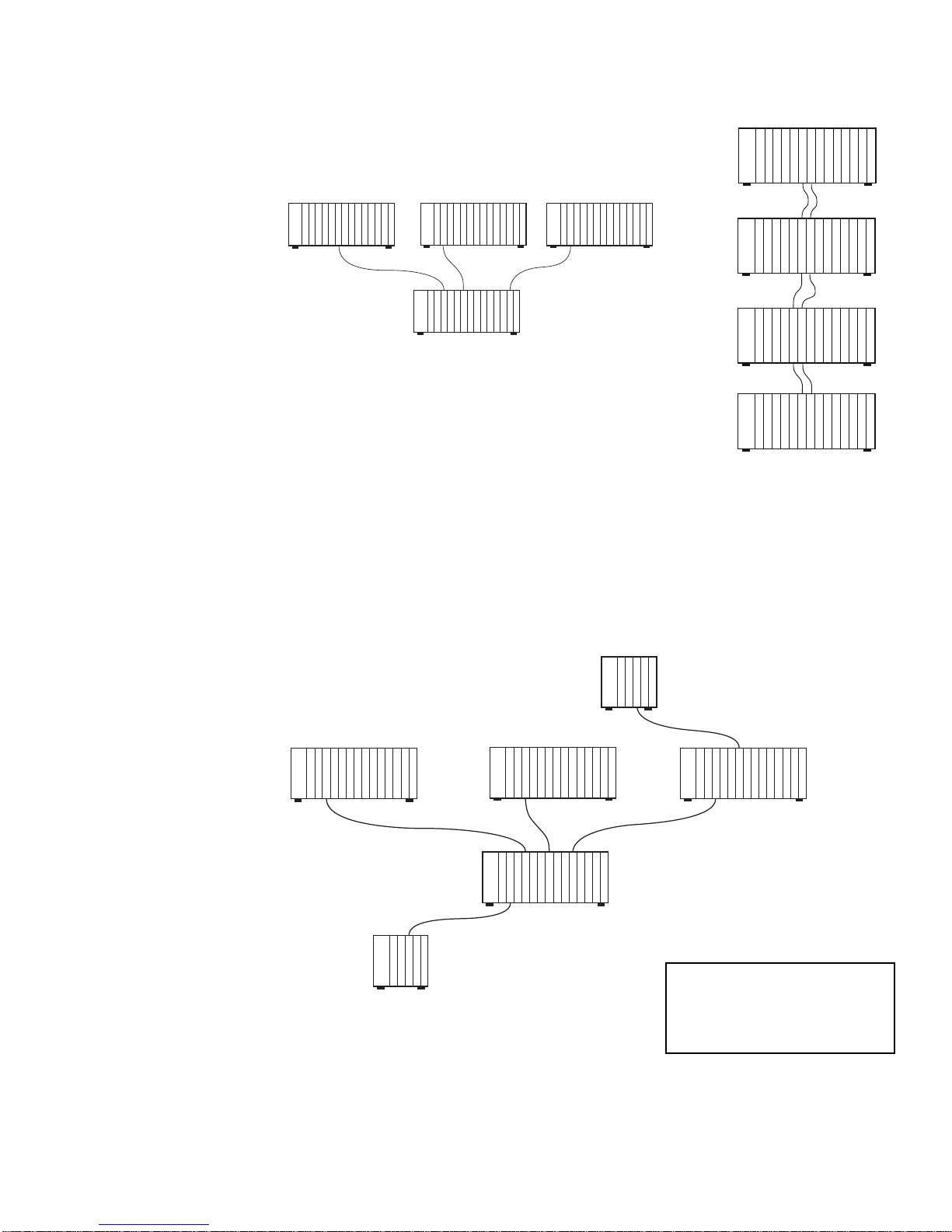
150'
150'
200'
X
P
X
T
X
P
A
C
X
P
A
C
X
P
A
C
X
P
X
R
X
P
A
C
X
P
A
C
X
P
A
C
X
P
L
U
X
P
A
C
X
P
A
C
X
P
X
R
X
P
X
R
X
P
X
R
X
P
X
T
X
P
X
T
X
P
X
T
Sample configurations
STAR
(Recommended for 60 or fewer
attached computers)
DAISY CHAIN
UNIT 4
UNIT 4 UNIT 3 UNIT 2
X
X
P
A
C
X
P
P
X
A
T
C
250'
X
X
X
P
X
T
X
P
P
P
A
A
A
C
C
C
250'
X
X
X
P
P
X
X
R
R
X
X
P
P
P
L
X
A
U
R
C
250'
X
X
X
X
P
P
P
P
X
A
A
A
T
C
C
C
UNIT 1
CONFIGURATION 1
In configurations 1 and 2, the user in Unit 1 can
UNIT 1
access any attached computer in units 1-4.
CONFIGURATION 2
COMBINATION
(Recommended for systems operating at distances over 250 feet away
or containing over 60 attached computers)
Configuration 3 shows that by combining the star and daisy chain configurations
into one system, you can support additional attached computers in a more
flexible environment.
UNIT 3 UNIT 4
X
X
X
X
X
X
X
X
X
P
P
P
P
P
P
P
P
P
L
L
L
L
A
A
A
A
X
U
U
U
U
C
C
C
C
T
X
X
P
P
A
X
C
T
250'
X
X
X
X
P
P
P
P
A
A
X
X
C
C
R
T
250'
X
X
X
X
P
P
P
P
A
A
L
X
C
C
U
R
UNIT 2
UNIT 1
CONFIGURATION 3
53
X
P
L
U
250'
UNIT 6
X
X
X
X
P
P
P
P
X
A
L
A
T
C
U
C
100'
UNIT 5
X
X
X
X
X
X
X
X
P
P
P
P
P
P
P
P
L
L
L
L
A
A
A
A
U
U
U
U
C
C
C
C
X
X
X
X
P
P
P
P
X
A
X
L
T
C
R
U
X
X
X
X
X
X
P
P
P
P
P
P
A
A
L
L
L
L
C
C
U
U
U
U
150'
X
X
X
X
X
X
X
P
P
P
P
P
P
P
A
A
L
L
X
X
L
C
C
U
U
R
R
U
XPAC - Attached Computer
XPLU - User Console
XPXR - Expansion Receiver
XPXT - Expansion Transmitter
Page 60

Computer/
User Console
Distribution
Once you have mapped out your optimal unit configuration, you'll need to
determine the placement of computers and user consoles within your system.
As you plan, consider the following:
1) In order for an attached computer to transmit its signal to users outside its
own XP4000 Series unit, there must be a transmitter present in the unit.
(See below)
2) In order for a user to receive signals from attached computers outside
its own XP4000 Series unit, there must be a receiver present in the unit.
(See below)
3) Each expansion cable connection between a transmitter and receiver pair
utilizes one of the four available paths in each unit. You may have up to
four separate active channels per unit at any one time. See Figure 5-1.
X
P
A
C
X
P
A
C
UNIT 3
X
P
L
U
UNIT 2
UNIT 1
X
P
L
U
X
P
A
C
X
P
L
U
X
P
A
C
X
P
A
C
X
P
A
C
USER IN UNIT 3 HAS ACCESS TO
LOCAL COMPUTERS ONLY
USER IN UNIT 2 HAS ACCESS TO
COMPUTERS IN UNITS 2 AND 3
USER IN UNIT 1 HAS ACCESS
TO ALL ATTACHED COMPUTERS
X
P
X
T
X
X
P
P
X
X
R
T
X
P
X
R
In the above example, the user in Unit 1 has access to its own local computers,
plus the computers in Units 2 and 3 because a transmitter is present in Units
2 and 3 and a receiver is present in Unit 1.
The user in Unit 2 cannot reach the computers in Unit 1 because no transmitter
is present in Unit 1.
The user in Unit 3 has access to the local computers only, because there is no
receiver present in the unit.
54
Page 61

Figure 5-1 below shows the path availability across units.
UNIT 3
UNIT 1
UNIT 2
In the above example, the user at Unit 1 would like to access computer 2H. There is
a valid path out of Unit 1 to accommodate that. However, all four paths in Unit 2 are
currently taken by the four local users. The only way the user in Unit 1 can access a
computer in Unit 2 is through sharing. He may view the video on any channel but will
not have keyboard or mouse control unless the Unit 2 user relinquishes control.
However, the Unit 1 user can access computer 3K independently, because there are
three open paths available in Unit 3. There is only one user in Unit 3, using computer
3B, taking one of the four available paths.
55
Page 62
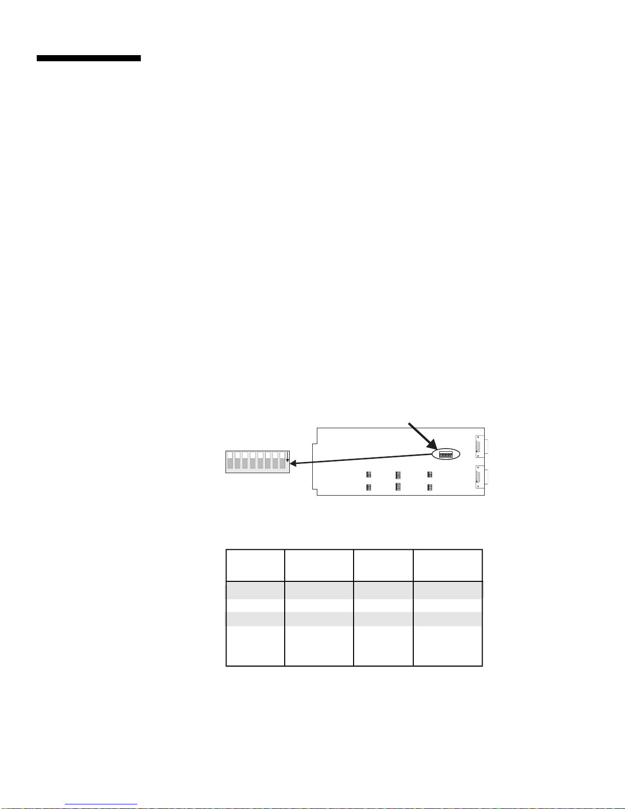
Transmitter/
Receiver Board
Configuration
Before installing your transmitter and receiver boards in your XP4000 system,
you will need to configure them for your system requirements. There are two
steps to configuring your expansion boards:
1) Configuring the 8-position DIP switch on the transmitter boards with a
unit address.
2) Configuring the jumpers on the transmitter and receiver boards for your
specific expansion cable length.
Please note that the same settings apply to both the standard and Category 5
expansion transmitter and receiver cards.
Configuring the Transmitter DIP Switch
All units that contain transmitters must be given a unique unit address that you
determine. Unit addresses are numeric, and may be any value between 1 and
254. Please note that unit addresses of “0” and “255” are reserved. Every
transmitter in a given unit must be configured for the same unit address for
proper operation.
To set the DIP switch on your transmitters, follow the steps below:
1) Locate all of the transmitters that will be installed in a single XP4000
Series unit.
2) Orient your first transmitter board as shown below, and locate the colored
DIP switch assembly.
DIP SWITCH
N
O
87654321
JP16JP20JP24
JP15JP19JP23
JP14JP18JP22
JP13JP17JP21
JP4JP8JP12
JP3JP7JP11
JP2JP6JP10
JP1JP5JP9
PWB: 016-0102 REV. A
EXPANSION REMOTE USER TRANSMITTER
87654321
DEFAULT
O
N
JP26
JP25
3) Choose a unique unit address and configure your transmitter board according
to the table below. For unit addresses higher than 12, see Appendix H.
Unit (8 ------ 1) Unit (8 ------- 1)
Address Setting Address Setting
1 00000001 7 00000111
2 00000010 8 00001000
3 00000011 9 00001001
4 00000100 10 00001010
5 00000101 11 00001011
6 00000110 12 00001100
4) Configure every remaining transmitter board for this specific XP4000
Series unit with the same address.
5) Set these transmitters by the applicable XP4000 Series unit. Locate all
transmitters that will be installed in your next XP4000 Series unit, and
repeat steps 2 - 5 until you have reached the last XP4000 Series unit in
your system.
56
Page 63
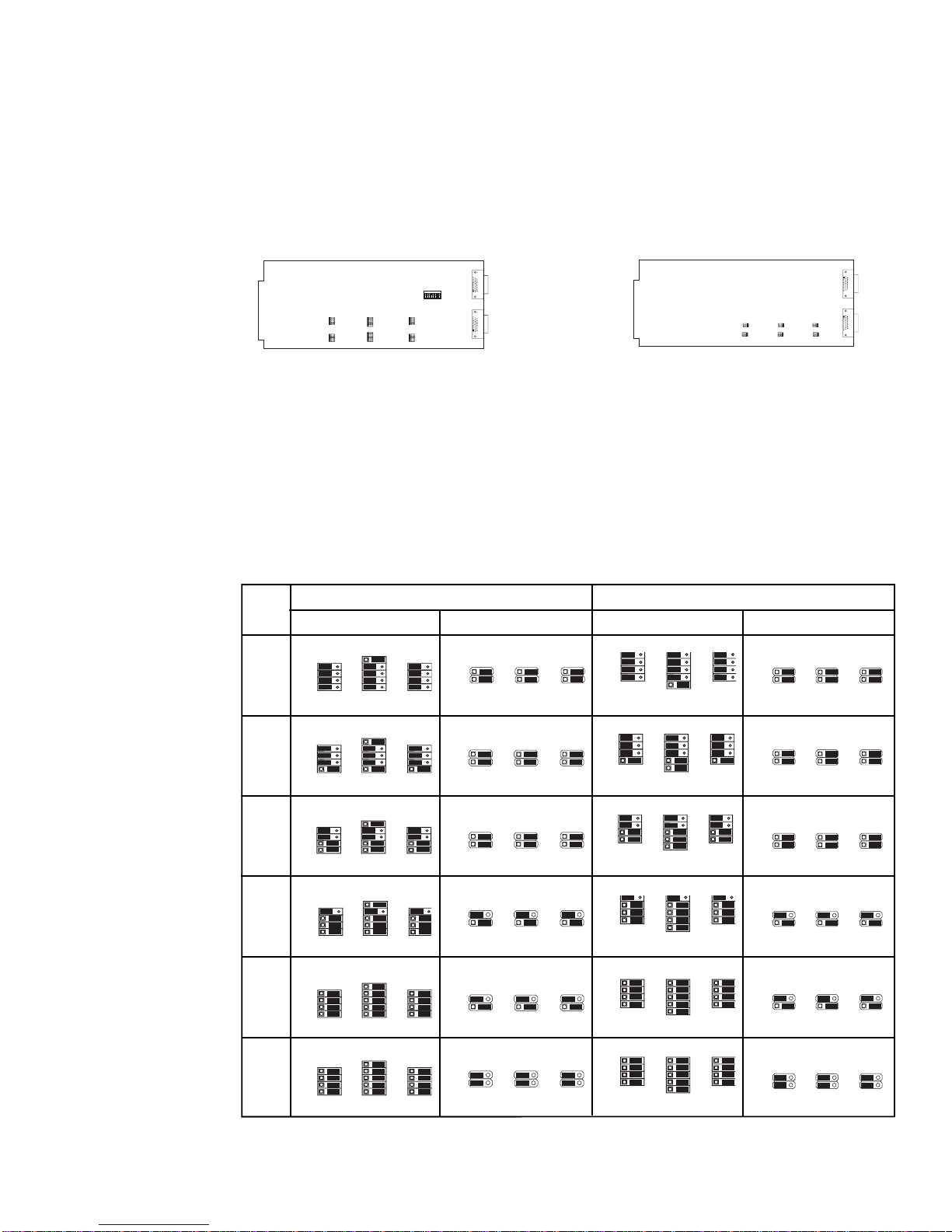
P
JP25
JP25
P
JP13JP17JP21
JP26
JP14JP18JP22
JP15JP19JP23
JP16JP20JP24
JP13JP17JP21
JP26
JP14JP18JP22
JP15JP19JP23
JP16JP20JP24
JP16JP20JP24
JP13JP17JP21
JP26
JP14JP18JP22
JP15JP19JP23
JP16JP20JP24
JP13JP17JP21
JP26
JP14JP18JP22
JP15JP19JP23
JP16JP20JP24
Configuring the Transmitter /Receiver Board Jumpers
Every transmitter and receiver pair must be configured for the length of the expansion
cable that connects them together.
Follow the steps below for each transmitter/receiver pair in your system:
1) Orient your first transmitter/receiver pair as shown below. Note that most
components have been removed to simplify the drawings.
EXPANSION RECEIVER 4XP
PWB: 016-0112 REV. A
N
O
87654321
JP16JP20JP24
JP15JP19JP23
JP14JP18JP22
JP13JP17JP21
JP26
JP25
JP4JP8JP12
JP3JP7JP11
JP2JP6JP10
JP1JP5JP9
PWB: 016-0102 REV. A
EXPANSION REMOTE USER TRANSMITTER
JP8 JP10 JP12
111
111
JP7 JP9 JP11
JP2 JP4 JP6
111
JP1 JP3 JP5
111
Default setting
TRANSMITTER
(XPXT OR XPST)
RECEIVER
(XPXR OR XPSR)
2) Choose which port on the transmitter/receiver you will be connecting your
expansion cable to: the upper Port 2, or the lower Port 1. Either port may be used,
but the same port must be chosen on transmitter and receiver.
3) Using the table below, configure the appropriate jumpers on each board according
to the port chosen and the length of the expansion cable that will connect them. Fill
out the Expansion Configuration Sheets in Appendix B for each board as you
configure it.
Expansion Port 1 Expansion Port 2
Dist. XPXT/XPST XPXR XPXT/XPST XPXR
3'
to
25'
26'
to
75'
76'
to
125'
JP25
JP7
JP9
JP4JP8JP12
JP3JP7JP11
JP2JP6JP10
JP1JP5JP9
JP4JP8JP12
JP3JP7JP11
JP2JP6JP10
JP1JP5JP9
JP4JP8JP12
JP3JP7JP11
JP2JP6JP10
JP1JP5JP9
JP8
JP8
JP8
1
1
1
JP10
1
JP7
1
1
1
JP10
1
JP7
1
1
1
JP10
1
JP11
1
JP12
1
JP9
JP11
1
JP12
1
JP9
JP11
1
JP12
1
JP26
JP26
JP15JP19JP23
JP14JP18JP22
JP13JP17JP21
JP16JP20JP24
JP15JP19JP23
JP14JP18JP22
JP13JP17JP21
JP1
JP3
JP5
1
1
1
JP2
1
JP1
1
JP2
1
JP1
1
JP2
1
JP6
1
1
JP4
JP3
JP5
1
1
JP6
1
1
JP4
JP3
JP5
1
1
JP6
1
1
JP4
126
to
175'
176'
to
225'
226'
to
250'
4) After all of the boards have been configured, you may proceed to the next section,
“Transmitter/Receiver Board and Expansion Cable Installation”.
JP25
JP4JP8JP12
JP3JP7JP11
JP2JP6JP10
JP1JP5JP9
J
25
JP4JP8JP12
JP3JP7JP11
JP2JP6JP10
JP1JP5JP9
J
25
JP4JP8JP12
JP3JP7JP11
JP2JP6JP10
JP1JP5JP9
JP7
JP9
JP11
1
1
JP8
JP8
JP8
1
JP10
1
JP7
1
1
1
JP10
1
JP7
1
1
1
JP10
1
1
JP12
1
JP9
JP11
1
JP12
1
JP9
JP11
1
JP12
1
JP1
JP3
JP5
1
1
1
JP2
1
JP1
1
JP2
1
JP1
1
JP2
1
JP6
1
1
JP4
JP3
JP5
1
1
JP6
1
1
JP4
JP3
JP5
1
1
JP6
1
1
JP4
57
Page 64
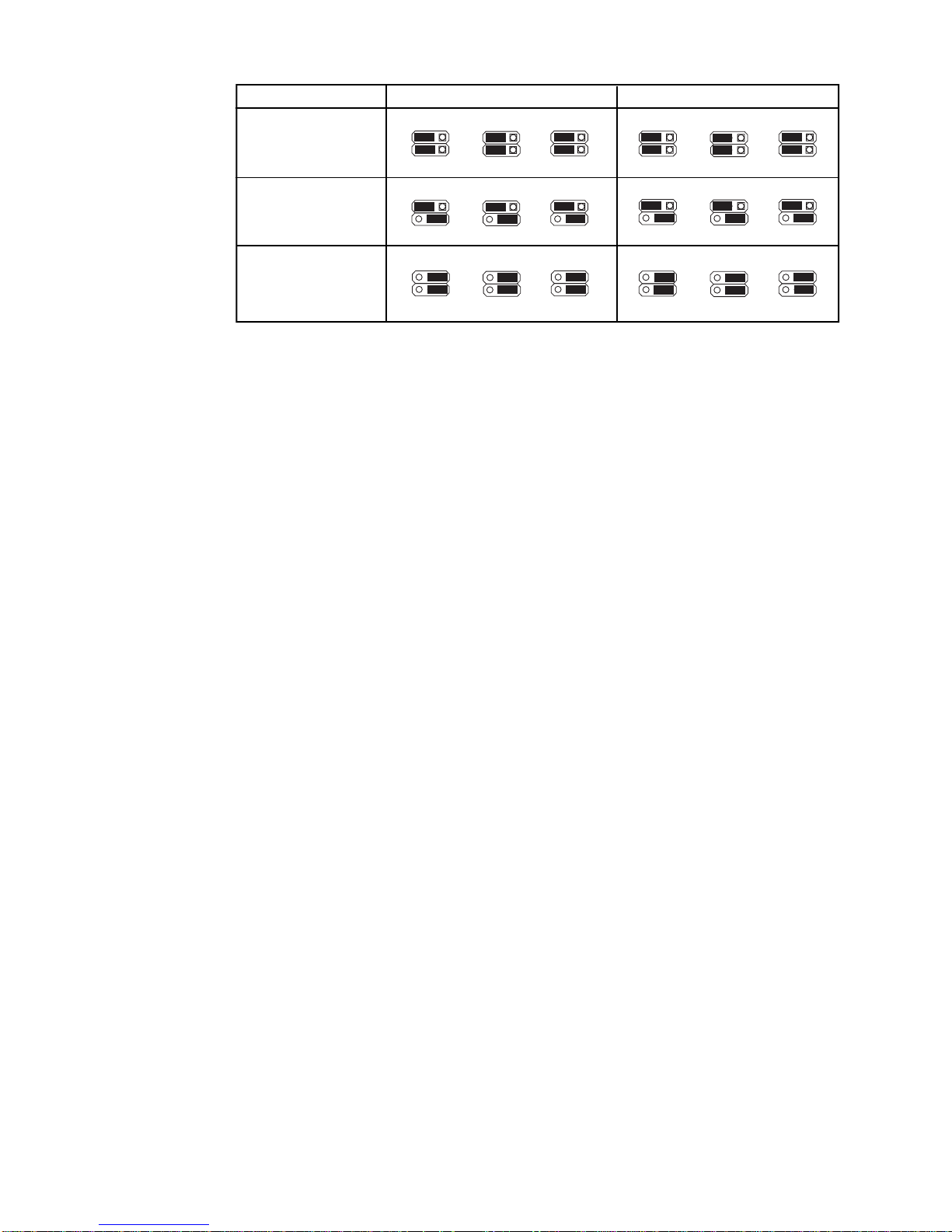
Default setting
Distance
3' to 125'
XPSR Bank 2
JP6 JP4
1
1
JP5 JP3
XPSR Bank 1
JP2
JP1
1
1
1
1
JP12 JP10
1
1
JP11 JP9
JP8
JP7
1
1
1
1
126' - 225'
226' - 250'
JP6 JP4
1
1
JP5 JP3
JP6 JP4
1
1
JP5 JP3
JP2
JP1
JP2
JP1
1
1
1
1
1
1
1
1
JP12 JP10
1
1
JP11 JP9
JP12 JP10 JP8
1
1
JP11 JP9
JP8
JP7
JP7
1
1
1
1
1
1
1
1
58
Page 65
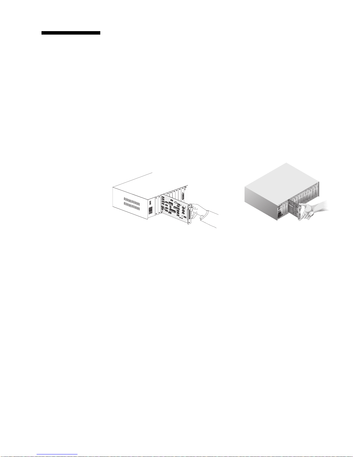
Transmitter/
Receiver Board
and Expansion
Cable Installation
Installing the
transmitter/receiver
boards
To install your transmitter/receiver boards in your XP4000 Series units, follow
the steps below:
1. Position the unit so that the rear panel is facing you, and choose an
available slot.
2. Remove the panel covering the available slot by unscrewing the two
Phillips-head screws on the rear of the unit that hold the panel in place.
3. Locate the two Phillips-head screws on the transmitter or receiver board,
located above and below the two connectors. Back these screws out until
they are flush with the transmitter/receiver board cover plate.
4. Slide the transmitter or receiver board gently into the open slot of the
XP4000 Series unit until the connectors line up flush with the back of the
unit. See the diagram below.
Connecting the
expansion cables
(XPST SHOWN)
(XPXT SHOWN)
5. Retighten the holding screws completely. DO NOT overtighten.
Follow the above procedure for every transmitter/receiver pair in your system.
To connect your expansion cables, follow the steps below:
1) Locate the expansion cable with the length that matches the jumper
settings of your first transmitter/receiver pair.
If you are using the XPXT and XPXR Transmitter and Receiver Boards
2) Connect the female 26-pin connector on the expansion cable into the male
26-pin connector on the transmitter. (Remember to select the correct port
for your configuration.)
3) Connect the male 26-pin connector on the expansion cable into the female
26-pin connector on the receiver. (Be sure and connect to the same port on
transmitter and receiver.)
59
Page 66

4) Tighten the thumb screws on each end of the extension cable, and repeat steps 14 for every expansion cable in the system.
If you are using the XPST and XPSR Transmitter and Receiver Boards
2. The connectors for the XPST consist of two banks of three modular connectors
each.(See diagram below) Connect one end of the Category 5 UTP cable to the
video port on either bank of connectors on the transmitter. Connect the other
end of the cable to the video port on the receiver.
3. Repeat the above process with the keyboard/mouse and multimedia cables until
all banks are connected. Be sure that the cables on the transmitter connect to
the same functions on the receiver.
You do not have to connect the multimedia cables if you aren’t using the
multimedia capabilities.
You will know when your expansion cables are installed properly by observing
the LEDs on the front panel of the unit. If you are using a Rear Access model
of the XP4040 or the XP4080, your cables are installed correctly in Bank 2
when the upper (amber) LED for the corresponding transmitter board is lit. If
your cables are installed correctly in Bank 1, the lower (green) LED will be lit.
If you have installed transmitters with conflicting unit addresses in the same
unit, the amber and green LEDs will flash alternately.
Standard 4-Pair
Wiring Color Codes
Pair 1 T White/Blue
R Blue/White
Pair 2 T White/Orange
R Orange/White
Pair 3 T White/Green
R Green/White
Pair 4 T White/Brown
Functions
Multimedia
Keyboard, Mouse
Video
Multimedia
Keyboard, Mouse
Video
Bank 2
Bank 1
Pair 3
PR2 PR1 PR4
+ - + - + - + -
T R T R T R T R
1 2 3 4 5 6 7 8
R Brown/White
(BELDEN 1583A OR EQUIVALENT)
CABLE PINOUT
If you are using the front access model of the XP4040, the green LED will light when
the cable in either port is installed correctly. Similarly, if you have transmitters in the
same unit with conflicting unit addresses, the green LED will flash.
60
Page 67

6
XP4400
XP4400
Overview
The XP4400 component of the XP4000 Series is designed to allow the
configuration of larger, more complex installations in the most efficient,
economical way possible. By channeling expansion signals from users to
attached computers, the XP4400 enables the most streamlined configuration
possible and can greatly reduce the number of units, transmitter/receiver cards
and cables in the system. The example below shows a simple 16 x 16 matrix
configured with and without the XP4400. All users in this system can access
any computer at any time.
16 X 16 MATRIX USING XP4040 UNITS
REQUIRES:
8 XP4040 UNITS
32 XPST TRANSMITTER CARDS
32 XPSR RECEIVER CARDS
128 CATEGORY 5 EXPANSION CABLES
16 X 16 MATRIX USING XP4400 UNITS
REQUIRES:
8 XP4040 UNITS
1 XP4400 UNIT
1 RX4400 RECEIVER MODULE
1 TX4400 TRANSMITTER MODULE
8 XPST TRANSMITTER CARDS
8 XPSR RECEIVER CARDS
64 CATEGORY 5 EXPANSION CABLES
61
Page 68

The XP4400 consists of a 9U high chassis, containing two power supplies, two
fan assemblies and a user specified number of transmitter and receiver modules.
The power supplies are fully redundant and hot swappable, allowing you to
replace one at any time without powering down the system. Fan assemblies are
also hot swappable, but both are needed to cool a fully loaded XP4400 chassis.
Each transmitter and receiver module contains 16 sets of video and keyboard/
mouse ports, enabling a module to attach to as many as 16 expansion ports,
using two Category 5 cables each. The XP4400 holds up to nine transmitter or
receiver modules per chassis.
TRANSMITTER AND
RECEIVER MODULES
POWER/FAN MODULE
62
Page 69

Features and
Benefits
LCD menu system
The XP4400 features a front panel LCD display for easy system configuration
and identification. Display system connection information, check the hardware
and firmware revision of your modules or troubleshoot system errors all from
an easy-to-use menu.
Front panel LEDs
FLASH upgrade
capability
Hot swappable
components
Installation
LEDs on the XP4400’s front panel let you monitor system power and error
status at a glance. The red LED blinks when a problem is detected, then goes to
solid when the problem is acknowledged. The LED will remain lit until the
problem is resolved, or begin blinking again if a new problem is discovered.
As with all XP4000 Series products, the XP4400 is FLASH upgradeable.
FLASH technology allows you to upgrade the XP4400’s firmware without
removing modules or powering down the system. New firmware revisions are
uploaded into the XP4400 via the serial port on the front panel or through
standard XP4000 Series serial connections. All advanced serial port operations
available through the host unit are also possible through the XP4400 serial port.
The power supplies, fan assemblies and the transmitter/receiver modules in the
XP4400 are all hot swappable. The ability to remove and replace components
without powering down the system or attached servers, means that maintenance
can be performed during business hours without interrupting system users.
The power supplies for your XP4400 are shipped uninstalled to prevent damage.
As a result, the first step in installing your expansion unit will be to assemble
the chassis.
Assembling the XP4400 Chassis
1) Locate the power supplies and remove them from their packaging.
2) Make sure that the power supplies are disconnected from the wall and
their power switches are in the ‘OFF’ position.
3) Gently slide the power supplies into their mounting brackets on the left
side of the XP4400 unit.
4) Connect a power cord to each of the power supplies and then to an
outlet. Switch on both of the power supplies and verify that the fan
modules work.
Configuring the Transmitter and Receiver Modules
5) Next you will need to configure the DIP switches on your Transmitter
Module. The XP4400 supports connections for 16 pairs of Category 5
cables. These ports are numbered 1 - 16 from left to right on the TX44
Transmitter Module. Each of these ports has three dip switches that
configure the port for the length of the Category 5 cable that is attached
to it.
63
Page 70

To configure the port, you will need to first select a pair of Category 5
cables that are connected to a receiver card in the system. Connect
these cables to the first available port with the Video cable connecting
to the upper jack and the Keyboard/Mouse cable connecting to the
lower jack. Locate the DIP switches that correspond to that port and
configure them as needed. (See diagram and settings below and on the
next page.)
Repeat this process for every port of every Transmitter Module in
your system.
XP4400
Transmitter
PORT 1
Dip Switch Area
#01
PORT 3
Dip Switch Area
#03
PORT 5
Dip Switch Area
#05
PORT 7
Dip Switch Area
#07
PORT 9
Dip Switch Area
#09
PORT 11
Dip Switch Area
#11
PORT 13
Dip Switch Area
#13
PORT 15
Dip Switch Area
#15
PORT 2
Dip Switch Area
#02
PORT 4
Dip Switch Area
#04
PORT 6
Dip Switch Area
#06
PORT 8
Dip Switch Area
#08
PORT 10
Dip Switch Area
#10
PORT 12
Dip Switch Area
#12
PORT 14
Dip Switch Area
#14
PORT 16
Dip Switch Area
#16
Port 1
Video
Keyboard/
Mouse
Port 2
Port 3
Port 5
Port 4
Port 6
64
Port 7
Port 8
Port 9
Port 10
Port 11
Port 12
Port 13
Port 14
Port 15
Port 16
Page 71
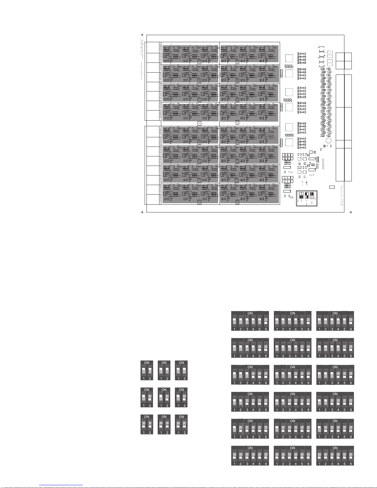
PORT 1
Dip Switch Area
PORT 2
Dip Switch Area
XP4400
Receiver
PORT 3
Dip Switch Area
PORT 5
Dip Switch Area
PORT 7
Dip Switch Area
PORT 9
Dip Switch Area
PORT 11
Dip Switch Area
PORT 13
Dip Switch Area
PORT 15
Dip Switch Area
PORT 4
Dip Switch Area
PORT 6
Dip Switch Area
PORT 8
Dip Switch Area
PORT 10
Dip Switch Area
PORT 12
Dip Switch Area
PORT 14
Dip Switch Area
PORT 16
Dip Switch Area
6) Once the Transmitter Modules are configured, gently slide them into the
XP4400 chassis and tighten the retaining screws.
7) Repeat step 5 with the Receiver Modules using the settings below. Note
that the Category 5 cables connecting to the RX44 Receiver Module will
Transmitter Settings
226-250ft
Receiver Settings
226-250ft
126-225ft
3-125ft
176-225ft
126-175ft
76-125ft
26-75ft
3-25ft
65
Page 72

be connected to a transmitter card in the system.
Setting the Chassis ID Number
8) Connect power to both power supplies and switch them on.
9) Finally, you will need to set the chassis number for your XP4400. This
is done through the LCD menu on the front of the unit.
As soon as you power on your XP4400 unit, the Idle Display menu will
appear. From this menu, press the Down button to reach the Chassis ID
menu. To set or change your chassis ID, press the Right button. The
following menu will appear:
Chassis ID
->new ID ###
old ID ###
****EDIT MODE****
The old ID is shown. Press the Up and Down buttons to set a new chassis ID for your XP4400 unit. Each XP4400 in your system will need to
have a unique ID number. Press the Right button to save the changes
and return to the Chassis ID Menu. Press the Left button to return to the
Chassis ID Menu without saving. If neither button is pressed within 5
seconds of your last change, you will automatically return to the Chassis
ID Menu without saving the changes.
LED Operation
The front panel of the XP4400 support two LEDs - green and red. The green
LED is lit when system power is on. If an error is detected with one of the fan
modules or power supplies, the red LED will begin to blink. This LED will
remain blinking until you check the LCD display System Status menu to view
the detected problem. (See the section ‘LCD Display Operation’ for details.) At
this point, the red LED will remain lit steadily until the problem is resolved. If
an additional problem is detected, the red LED will begin blinking again.
66
Page 73

LCD Display
Operation
The XP4400 front panel supports a 4x20 character LCD display which is used
to configure and display status for your XP4400 unit. As soon as you power on
your XP4400 unit, the Idle Display Menu appears as shown below:
----XP 4400---Chassis 000
www.cybex.com
The Contrast Menu
If your display is either too bright or cannot easily be seen, press the Right
button to reach the Contrast Menu.
DISPLAY CONTRAST
0 100%
########
****EDIT MODE****
Use your Up and Down buttons to increase or decrease the contrast of your
display. Press the Right button to save the changes and return to the Idle
Display Menu. Press the Left button to return to the Idle Menu without saving.
If neither button is pressed within 5 seconds of your last change, you will
automatically return to the Idle Display Menu without saving the changes.
The Chassis ID Menu
From the Idle Display Menu, press the Down button to reach the Chassis ID Menu.
Chassis ID
0
The first time you power on your XP4400 unit, the Chassis ID will read as “0”.
NOTE: You must change this to a valid system chassis ID before integrating
the XP4400 into your configuration.
To set or change your chassis ID, press the Right button. The following
menu appears:
Chassis ID
->new ID ###
old ID ###
****EDIT MODE****
The old ID is shown. Press the U p and Down buttons to set a new chassis ID for
your XP4400 unit. Press the Right button to save the changes and return to the
Chassis ID Menu. Press the Left button to return to the Chassis ID Menu
without saving.
67
Page 74

The System Identification Menu
From the Chassis ID Menu, press the Down button to reach the System
Identification Menu.
***Slot in Use***
A B C D E F G H I
RTT
Scan On
This menu displays the type of module installed in each of the XP4400’s nine
available slots, labeled A through I. An “R” indicates a receiver module is
installed, a “T” indicates a transmitter module.
For more detailed information about your installed modules, press the Right
button. The following menu appears:
Slot A: type
Hardware: ###
Firmware: ###
Ser.No #: ###
Hardware, firmware and serial numbers are displayed for the module located in
slot A of your XP4400 unit. Press the Up and Down buttons to cycle through the
information for all nine slots. When you are finished viewing this information
press the Left button to return to the System Identification Menu.
The System Status Menu
From the System Identification Menu, press the Down button to reach the
System Status Menu.
*** SYSTEM STATUS ***
FAN modules OK!
PSU1 : OK
PSU2 : OK
If the red LED on your XP4400’s front panel is blinking, this menu will show
you where the problem lies. Once you leave this menu, via the Left button, the
blinking light will change from blinking to solid until the problem is resolved.
The LED will go off when the problem is resolved. If a second problem occurs,
the light will begin blinking again.
For more detailed information about the fan assemblies or the power supply
output voltages, press the Right button. The following menu appears:
+5V:ok +12V:ok
-5V:ok -12V:ok
D5V:ok AC:ok DC:ok
lower power supply
Press the Up and Down buttons to cycle through the information for the upper
and lower power supplies and fan assemblies. When you are finished viewing
this information, press the Left button to return to the System Status Menu.
68
Page 75

The Serial Port Configuration Menu
From the System Status Menu, press the Down button to reach the Serial Port
Configuration Menu.
***Serial Port***
Baud Rate:57600
Data Bits:8
Parity:No Stop:1
This menu displays the settings that the serial port requires your PC to be
configured for. Only the baud rate is user configurable. To change the baud rate,
press the Right button. The following menu appears:
***Edit Mode***
Baud Rate:57600
Data Bits:8
Parity:No Stop:1
Press the Up and Down buttons to cycle through the available rates. When you
have made your selection, press the Right button to save the changes and
return to the Serial Port Configuration Menu. Press the Left button to return
without saving.
The Link Status Menu
From the Serial Port Configuration Menu, press the Down button to reach the
Link Status Menu.
***Link Status***
Slot: A Port: 05
Link: 65-B-12
This menu displays connection information for every port of every slot in the
XP4400. In the sample menu above, port 5 of slot A on the XP4400 is connected
to another XP4400 unit with a chassis address of 65 in slot B, port 12.
To view the connections of another slot and port, press the Right button. The
following menu appears:
Select Slot
-> Slot: A
Port: 05
Link: 65-B-12
Press the Up and Down buttons to select the appropriate slot on the XP4400
chassis. When you have made your selection, press the Right button again. The
following menu appears:
Select Port
Slot: A
-> Port: 05
Link: 65-B-12
69
Page 76

Press the Up and Down buttons to select the port you wish to display
information for. Each transmitter or receiver module has 16 ports available
for connection. When you have made your selection, press the Left button to
return to the Link Status Menu. The link information for the requested slot and
port will be displayed.
The Language Menu
From the Link Status Menu, press the Down button to reach the Language Menu.
*** Language ***
- ENGLISH -
This menu displays the language that your menu system is currently being
viewed in. To change to a different language, press the Right button. The
following menu appears:
Select Language
- English **** EDIT MODE****
FLASH
Upgrading
The old language is shown. Press the Up and Down buttons to select a new
language from the available choices. Press the Right button to save the
changes and return to the Language Menu. Press the Left button to return
without saving.
Like all XP4000 Series units, the XP4400 is FLASH upgradeable. FLASH
technology allows you to upgrade the XP4400’s firmware without removing
modules or powering down the system. New firmware revisions are uploaded
into the XP4400 via the serial port on the front panel or through standard serial
connections. All advanced serial port operations are possible through the
XP4400 serial port. For more information on FLASH upgrading XP4000 Series
components, see Chapter 9, Advanced Operations.
70
Page 77

Sample
Configurations
There are many configurations possible with the XP4400 in your XP4000
system. Below are several common examples. For a configuration sample
specific to your system, contact the Cybex Sales Department.
16 x 128 matrix
This configuration illustrates a matrix of 16 users with the simultaneous
capability to access 128 attached computers. Any user can connect to any
computer in the system without limitation or interference from another system
user. Should two people need access to the same computer at the same time,
they can share access. Both users can view the computer’s video, while one
user at a time will have keyboard/mouse control. This configuration utilizes 1
XP4400 unit, 6 XP4080 chassis to connect computers to the system, and 4
XP4040 chassis to connect the users.
71
Page 78

16 x 384 matrix
This configuration illustrates a matrix of 16 users with the simultaneous
capability to access 384 attached computers. Any user can connect to any
computer in the system without limitation or interference from another system
user. Should two people need access to the same computer at the same time, they
can share access. The addition of 256 additional computers added 2 XP4400
units to the prior system. Therefore, this configuration utilizes 3 XP4400 units,
48 XP4080 chassis to connect computers to the system, and 4 XP4040 chassis
to connect the users.
72
Page 79
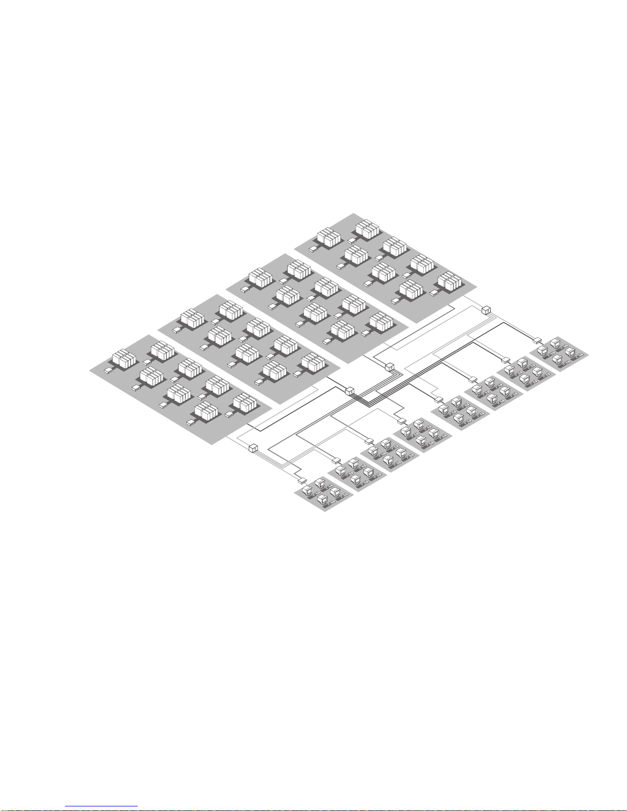
32 x 256 matrix
This configuration illustrates a matrix of 32 users with the simultaneous
capability to access 256 attached computers. Any user can connect to any
computer in the system without limitation or interference from another system
user. Should two people need access to the same computer at the same time, they
can share access. This configuration is especially useful when a large number
of users need simultaneous access to several hundred system computers. This
configuration utilizes 4 XP4400 units, 32 XP4080 chassis to connect computers
to the system, and 8 XP4040 chassis to connect the users.
73
Page 80

74
Page 81

7
Basic Operations
LEDs and
Front Access
Display
Computers may be powered up one at a time or all at once. Operator intervention
is not necessary during booting. With the front access model, a computer may
be selected at the local console by pressing the push-button for that computer
channel. The channel letter will then be shown on the alphanumeric display.
All other user consoles select computer channels through a keyboard sequence
described on the next page. The indicator lights (LEDs) over the push-buttons
will change to reflect the status of each attached computer or secondary
console. See the tables below.
Front Access Model
Computer state Channel LED state
Connected Powered Selected
No No No Off
Ye s N o N o O f f
Yes Yes No On, Low intensity
Yes No Yes Blinking: On/Off (1HZ)
Yes Yes Yes Blinking: On/Low intensity (1HZ)
Secondary console state
Not installed Off
Installed On, Full intensity
Installed - in Command Mode Blinking: On/Off (2HZ)
Connected Powered Selected Amber Green
Rear Access Model
Computer state Channel LED state
No No No Off Off
Yes No No Off Off
Yes Yes No Off On
Yes No Yes On Off
Ye s Ye s Ye s O n O n
Secondary console state
Not installed Off
Installed On
Installed - in Command Mode Blinking
75
Page 82

Reading the LED status
indicators
When you are switching channels with the keyboard or using the KeyScan
feature, you must first place your system in Command Mode. As long as you
are operating in Command Mode, whatever you type will be intercepted by
your XP4000 Series unit until the Enter or the Escape key is pressed to end
Command Mode. None of the keystrokes entered will be forwarded to the
attached computer. While you are in Command Mode, the Num Lock, Caps
Lock and Scroll Lock lights on your keyboard will blink or “Command Line”
will appear on your monitor until you press enter or escape. For more
information on placing your system in Command Mode, see the “Keyboard
Control” section next in this chapter.
If you are using a rear access model of an XP4000 Series unit, you will notice 2
LEDs above each channel letter on the front of your unit: one amber and one green.
These lights, when representing the status of transmitter or receiver boards, are
normally both on. This indicates that the boards and expansion cables have been
properly installed. Error conditions which would cause these indicators to either
blink or go out are shown in the table below. Note that if you are using a front access
model, you will only have the green status LED. This LED will be lit if either Port
1 or Port 2 is installed correctly.
Amber LED Green LED
Board Standard Error Standard Error
Transmitter ON ON
OFF; Expansion cable,
Port 2 is not properly
installed.
OFF; Expansion cable,
Port 1 is not properly
installed.
Reading the front
access model front
panel display
OR
BLINKING; The transmitter was configured
with a different address
than another transmitter
in the same unit.
Receiver ON ON
OFF; Expansion cable,
Port 2 is not properly
installed.
BLINKING; The transmitter was configured
with a different address
than another transmitter
in the same unit.
OFF; Expansion cable,
Port 1 is not properly
installed.
OR
If you are using a front access model, you will have an alphanumeric display on
the front panel of the unit. This display reflects the active channel for the local
user console. For units with an address between 1 and 9, the display will show
the unit address and the channel. For units with addresses higher than 9, the
display will show an asterisk (*) in place of a unit address. For example, if
channel G in Unit 7 is the current active channel at the local console, the display
would show 7G. If channel K in Unit 12 is active, it would show *K.
76
Page 83

Multiplatform
Keyboard
Translation
XP4000 Series units allow you to use any type of keyboard to operate any
type of attached computer. However, when crossing platforms, certain keys
will need to be ‘remapped’ in order to provide all of the functions available
on the keyboard native to that platform. For example, if you access a Sun
workstation with a Macintosh keyboard, you will notice that the Macintosh
does not have the STOP and AGAIN keys that are on a true Sun keyboard.
But, by turning Scroll Lock on, the F1 and F2 keys on the Macintosh
keyboard function as the Sun STOP and AGAIN keys. With Scroll Lock off,
F1 and F2 function normally.
Below are the translation tables for PC, Macintosh and Sun keyboards. Where
“undefined” is designated, no characters will be transmitted to the computer.
Where “untranslated” is listed, the key will perform its standard function
regardless of the state of the Scroll Lock. All other mapped functions will only
be valid when the Scroll Lock is on.
PC Keyboard
Key Sun Mac Mac
(Translation Disabled1) (Translation Enabled1)
F1 STOP untranslated untranslated
F2 AGAIN untranslated untranslated
F3 PROPS untranslated untranslated
F4 UNDO untranslated untranslated
F5 FRONT untranslated untranslated
F6 COPY untranslated untranslated
F7 OPEN untranslated untranslated
F8 PASTE untranslated untranslated
F9 FIND untranslated untranslated
F10 CUT untranslated untranslated
F11 POWER POWER POWER
F12 COMMAND COMMAND OPTION
keypad * COMPOSE untranslated untranslated
NUMLOCK HELP untranslated untranslated
keypad / MUTE untranslated untranslated
keypad - VOL - untranslated untranslated
keypad + VOL + untranslated untranslated
ALT untranslated OPTION COMMAND
WINDOWS
2
COMMAND COMMAND COMMAND
1
See the section, “Attaching a Macintosh Computer” in Chapter 3 for information
on keyboard translation options.
2
Windows 95 104-key keyboard.
For Users connected to an Apple Macintosh with a “Windows 95” keyboard,
you may reverse the functions of the ALT and WINDOWS keys. Enter
Command Mode, type W95K and press Enter. This will map the ALT keys to
the Command/Apple key and the Windows key to the Alt/Option key.
77
Page 84

Mac Keyboard
Key Sun PC
F1 STOP untranslated
F2 AGAIN untranslated
F3 PROPS untranslated
F4 UNDO untranslated
F5 FRONT untranslated
F6 COPY untranslated
F7 OPEN untranslated
F8 PASTE untranslated
F9 FIND untranslated
F10 CUT untranslated
F11 untranslated untranslated
F12 untranslated untranslated
keypad * COMPOSE untranslated
NUMLOCK HELP untranslated
keypad / MUTE untranslated
keypad - VOL - untranslated
keypad + VOL + untranslated
POWER POWER undefined
COMMAND COMMAND undefined
Sun Keyboard
Key Mac PC
STOP undefined undefined
AGAIN undefined undefined
PROPS undefined undefined
UNDO undefined undefined
FRONT undefined undefined
COPY undefined undefined
OPEN undefined undefined
PASTE undefined undefined
FIND undefined undefined
CUT undefined undefined
POWER POWER undefined
COMMAND COMMAND undefined
COMPOSE undefined undefined
HELP undefined undefined
MUTE undefined undefined
VOL - undefined undefined
VOL + undefined undefined
78
Page 85

Keyboard
Control
The following notational conventions appear throughout this manual to
illustrate commands for operating your XP4000 Series unit. Whenever you see
one of the symbols listed on the left side of the table, substitute the
corresponding steps or values listed on the right side of the table.
Convention Key Sequence or Value
Enter Command Mode:
<CM> 1.Press and hold down the ‘Num Lock’ key.
2.Press and release the minus (-) key on the numeric keypad.
3.Release the ‘Num Lock’ key.
(Note: for alternate command mode sequences, see the section,
“Keyboard Switching with Different Cybex Products” in Chapter 9)
<Enter> Press the ‘Enter’ or ‘Return’ key. The <Enter> command is used to
execute an instruction and exit from Command Mode.
Addr Enter the letter that corresponds to the channel you wish to select.
[channel list] A channel list can be a single channel address (See above)
or
an address range, consisting of the low address followed by the high
address separated by a backslash, entered as
[Low Addr\High Addr].
<ESC> Press the ‘Escape’ key. The <ESC> command is used to exit
Command Mode without executing an instruction.
79
Page 86

Keyboard
Switching
Basic keyboard
switching
All users may utilize a short keyboard sequence to switch between channels.
A “Hotkey” sequence places your system in Command Mode. While in
Command Mode, whatever you type will be interpreted as system commands
until the Enter or the Escape key is pressed to end Command Mode, and will
not be forwarded to the attached computer.
Next, enter the address (Addr) for the channel you wish to select. A Channel
address is represented by a letter located on the front panel of the unit under
that channel's LED(s).
Press enter to accept the new channel. The following command line illustrates
the proper format used to switch your active channel with the keyboard.
Key Sequence Action
<CM>Addr<Enter> Selects an active computer channel with the keyboard.
Below is an example of keyboard switching, with an accompanying explanation.
Sample keyboard
switching commands
Key Sequence Action
1.<CM>D<Enter> Selects Channel D as the active channel.
2.<CM>A<Enter> Selects Channel A as the current active channel.
3.<CM>G<ESC> Exit Command Mode. The instruction is not executed.
Channel A is still the active channel.
For keyboard switching across multiple units, precede the channel of the computer
you want to switch to with the chassis number of the unit that it is attached to.
Below is an example of channel switching across multiple units, with an
accompanying explanation.
Key Sequence Action
1.<CM>8D<Enter> Selects Channel D in Unit 8 as the active channel.
2.<CM>76A<Enter> Selects Channel A in Unit 76 as the current active channel.
3.<CM>112G<ESC> Exit Command Mode. The instruction is not executed.
Channel A in Unit 76 is still the active channel.
Note: If no unit address is specified, the local unit is assumed.
80
Page 87

Multiuser
Operation
There are three ways to utilize the multiuser capabilities of the XP4000
Series. You may access computers independently, share access of computers
with other consoles, or use a combination of independent and shared access.
Each option is described below.
Independent Access
Up to four users per unit may operate four different attached computers
independently at the same time. Any combination of local and secondary
consoles may be used. In the diagram below, User Console 1 can access any
computer from A to F regardless of the type of keyboard and mouse at Console
1 or the type of computer being accessed.
Example: User Console 1 selects computer A. If Consoles 2, 3 and 4 want
independent access to an attached computer, they must choose from computers
B through F. In the above example, Console 2 has chosen computer B, Console
3 has chosen computer C, and Console 4 has chosen computer E to work on.
81
Page 88

Shared Access
If two or more consoles need to access the same computer, they can ‘share’
access to it through the XP4000 Series unit. Sharing means that multiple
consoles can view a computer channel at the same time, but only one can enter
data through the keyboard or mouse at any given moment. As soon as the active
console stops all keyboard and mouse activity, another console can take
control of the computer. The amount of time that a console must be inactive
before another console can take control is user-configurable and may be 1
second or 10 seconds. See Chapter 3, for more details.
Any console, local or secondary, can share access to any computer with any
other console in the system. There is no system limitation on the number of
consoles that can share access at the same time. All consoles in your system
can share access to all computers simultaneously as long as only four users per
unit are actively working.
User Console 1
Computer B
Video
Sharing
User Console 2
ComputerA
Computer B
Video
Computer B
Computer D
Computer C
Example: User Console 1 is currently using computer B. If a user at Console
2 switches to computer B, he will be able to observe Console 1 at
work. When all keyboard and mouse activity at Console 1 stops,
Console 2 may take control of computer B by simply moving the
mouse or typing on the keyboard. Console 1 is now the observer.
82
Page 89

Example: User Console 1 is currently using computer A. Consoles 2 and 3 are
sharing access of computer A with Console 1. When all keyboard
and mouse activity stops at Console 1, either Console 2 or Console
3 can take control of computer A. Only one console can work on
computer A at a time.
User Console 4 is currently working on computer B. Console 5 is
sharing access of computer B with Console 4 and can take control
of computer B when all keyboard and mouse activity stops at
Console 4. Only one console can work on computer B at a time.
83
Page 90
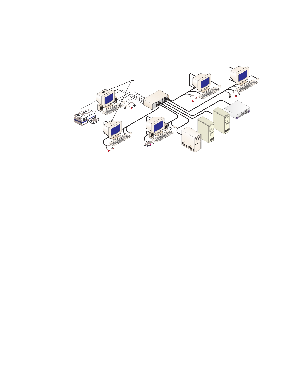
Combined Access
You can combine independent and shared access within one XP4000 Series
system. Up to four consoles per unit have independent access to four different
computers. If a fifth console enters the system, that user can share computer
access with any of the other four consoles.
User Console 5
User Console 4
Computer D
Sharing
Computer C
Video
Video
User Console 1
Computer A
Video
Computer D
Computer B
Computer A
Video
Video
Computer C
User Console 2
User Console 3
Computer B
Computer A
Example: User Consoles 3, 4, and 5 are using computers B through D
respectively. They are working simultaneously and independently
of each other. Consoles 1 and 2 are sharing computer A. Both
Consoles display video from computer A, but only Console 1 or 2
can be working on the computer at any given moment.
84
Page 91
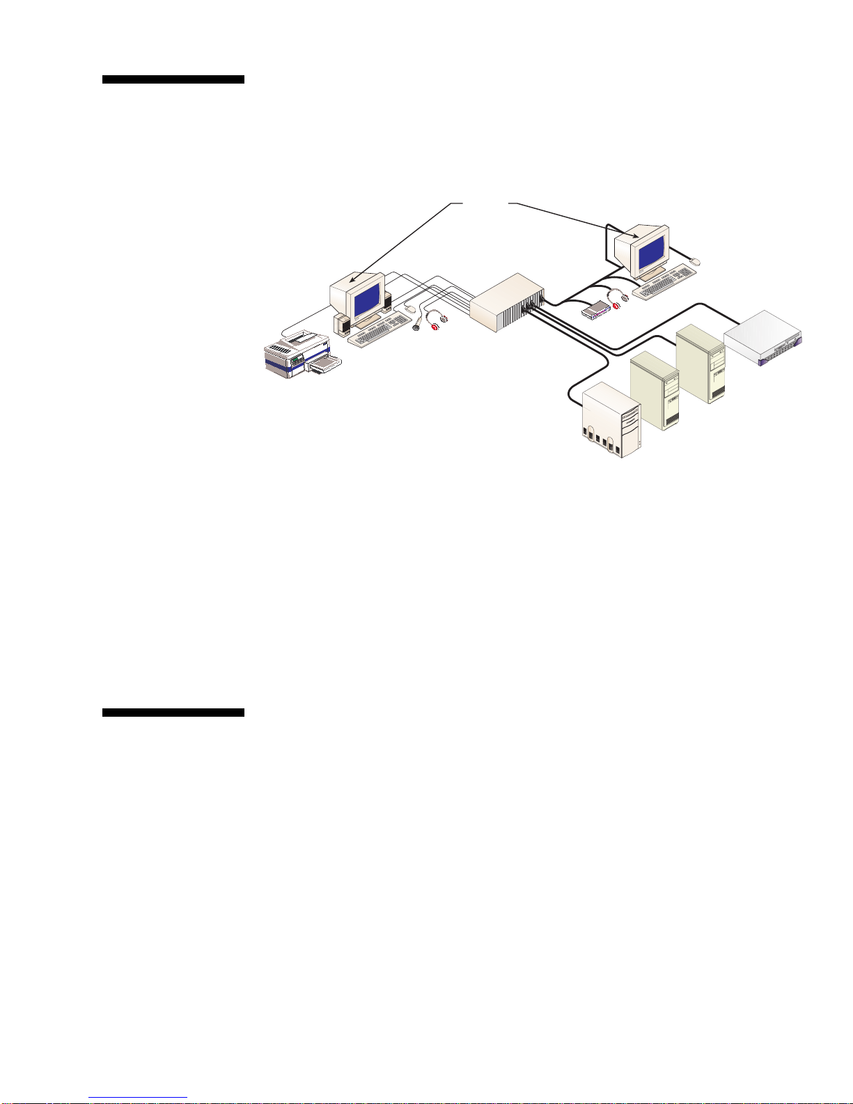
Multimedia
Operation
The XP4000 Series unit supports speakers and a microphone at every user
console in the system. If you have purchased user interface and computer
interface cables with multimedia capabilities, then you will have access to these
features. The speakers and/or microphone that you have connected to your
console will work exactly as if they are connected directly to your computer.
User Console 1
Computer B
Video
Sharing
User Console 2
ComputerA
Computer B
Video
Computer B
Computer D
Computer C
Example: User Console 1 is currently using computer B. The speakers and
microphone at Console 1 are active. When all keyboard and mouse
activity at Console 1 stops, Console 2 may take control of computer
B by simply moving the mouse or typing on the keyboard. Once
Console 2 takes control, the headphones at that station are active.
Serial
Peripherals
NOTE: Some speakers and microphones have different sized jacks than will
connect to the cables. If you encounter this situation, you will need to purchase
an adaptor to make the connection. These adaptors are commonly available;
contact your electronics supply store for more information.
The XP4000 Series units support any RS-232 serial peripheral that uses inband
(XON/XOFF) or hardware (RTS/CTS) flow control: hardware up to 9600 Baud,
inband to 115200 Baud. Examples include most modems, serial printers and
touch screens.
If you have user and computer interface cables with multimedia capabilities,
you will have access to these features. Simply connect your serial device to the
matching connector on your user interface cable, as if you were connecting it
directly to your computer. When your console has keyboard and mouse control
for a computer channel, you will also have serial device throughput.
85
Page 92

KeyScan
KeyScan lets you automatically scan your computer channels sequentially
without intervention. When KeyScan detects keyboard or mouse activity,
scanning is suspended until all activity stops. Scanning then resumes with the
next channel in sequence. The length of time each computer channel remains on
screen, or dwell time, is configurable and changeable at any time. If you have
multiple units in your system, you can control which units are included in the
scan process. Scanning is halted if the KeyScan Halt command is entered or if
another channel is selected.
KeyScan commands
Sample KeyScan
session
The following key sequences configure and control KeyScan. The first sequence
is used to configure the dwell time. The next two commands control which units
should be included in scanning. The Go command enables automatic scanning
with the current computer channel. The Halt command stops scanning. Scanning
is suspended while in Command Mode.
Key Sequence Action
<CM>KDnn<Enter> Configures the dwell time. Substitute nn with a value from 1 to
65 seconds. The default value is 5 seconds.
<CM>KMnnn<Enter> Sets the highest unit address that the system will scan through
during a session. Substitute nnn with a value from 1 to 254.
Required for expansion systems only.
<CM>KM0<Enter> Resets scanning to include channels in the local unit only.
<CM>KG<Enter> Enables the KeyScan Go command.
<CM>KH<Enter> Enables the KeyScan Halt command.
Below is a sample KeyScan session, with an accompanying explanation.
Key Sequence Action
1.<CM>KD10<Enter> Configures the dwell time. Each computer channel will remain on
the screen for 10 seconds before the next channel is displayed.
2.<CM>KM55<Enter> Configures the system to scan up through unit address 55 before
beginning at Unit 1 again.
3.<CM>KG<Enter> Go command. Scanning begins with the current channel.
4.<CM>KD3<Enter> Reconfigures the dwell time. Each channel will now remain on the
5.<CM>KH<Enter> Halt Command. Scanning is halted until the Go command is
6. <CM>KM0<Enter> Resets scanning to include channels in the local unit only.
7.<CM>KG<Enter> Go command. Scanning begins with the current channel. All
screen for 3 seconds before the next channel is displayed.
issued again.
channels in the local unit only will be scanned sequentially, then
the pattern repeated.
86
Page 93

Broadcast
Mode
Broadcast Mode allows each user to send commands to multiple computers
within your system at the same time. By creating your own customized “broadcast
groups”, you can designate which computers you want to broadcast to. Once
you enter Broadcast Mode, whatever you type is sent to all of the computers in
your group regardless of which channel is active. Broadcast groups may include
any type of module in the system, but only affect XPAC/XPAB computer
interface modules. Each XPAC/XPAB module can belong to only one broadcast
group at a time.
Go/Halt commands
Add/Remove channels
Sample broadcast
session
The following key sequences are used to configure and run Broadcast Mode.
When the Broadcast Go command is entered, all channels configured for
Broadcast Mode will begin broadcasting all keystrokes entered. Similarly,
when the Broadcast Halt command is entered, all channels will stop broadcasting.
Key Sequence Action
<CM>TG<Enter> Enables the Broadcast Go command
<CM>TH<Enter> Enables the Broadcast Halt command
Enter the Broadcast Add Channel (+) command to add channels to your
broadcast group. Use the Broadcast Remove Channel (-) command to delete
channels from the group. If you are currently in Broadcast Mode, these
commands will not take effect immediately. The channels will be added or
removed the next time the Broadcast Go command is entered.
Key Sequence Action
<CM>T+
<CM>T-
[channel list]
[channel list]
<Enter> Enables the Broadcast Add Channel (+) command
<Enter> Enables the Broadcast Remove Channel (-) command
Below is a typical broadcast session, with an explanation after each step.
Key Sequence Action
1.<CM>T-A-D<Enter> Removes channels A through D of the local unit from the
2.<CM>T+A-B<Enter> Configures channels A and B for broadcasting.
3.<CM>TG<Enter> The computers attached to channels A and B will receive all
4.<CM>T-A<Enter> Channel A will continue broadcasting, but will not broadcast
5.<CM>T+C<Enter> Channel C will not broadcast now, but will begin broadcasting
6.<CM>TH<Enter> All channels in the broadcast group (A and B) will stop
7.<CM>TG<Enter> All channels in the new broadcast group (B and C) will
8.<CM>T+1A-55N<Enter> Configures all XPAB/XPAC modules within the range of
broadcast group.
keys typed, even if neither channel is selected.
the next time the ‘Go’ command is entered.
the next time the ‘Go’ command is entered.
broadcasting.
receive all keys typed, even if neither channel is selected.
channels 1A through 55N for broadcasting.
87
Page 94

Follow Mode
Follow Mode allowsa user to follow another user's channel switching. For
example, John and Melissa are both users in an XP4000 Series system. John
wants to automatically change channels along with Melissa. John places his
console in Follow Mode, designating Melissa's user console as the leader.
Now, whenever Melissa changes to any channel, John automatically switches
to the same.
The following key sequences configure and control Follow Mode. The first
sequence designates the leader console. The remaining commands are used to
enable/disable Follow Mode and save the changes.
Key Sequence Action
<CM>FOLLOW
<CM>FOLLOW+<Enter> Enables Follow Mode
<CM>FOLLOW-<Enter> Disables Follow Mode
<CM>SAVE<Enter> Saves configuration to permanent memory
Addr
<Enter> Sets the address of the leader console to be followed
Swap Mode
Privacy Mode
Swap Mode allows two users to exchange channels with one channel switch.
For example, John and Melissa are both users in an XP4000 Series system.
When Melissa is working on John's computer, John wants to be automatically
switched to Melissa's computer and vice versa. John and Melissa both place
their consoles in Swap Mode. Now, John and Melissa will swap channels when
either one switches to the other's computer.
The following key sequences configure and control Swap Mode. The first
sequence designates the user console to be swapped with. The remaining
commands are used to enable/disable Swap Mode and save the changes.
Key Sequence Action
<CM>SWAP
<CM>SWAP+<Enter> Enables Swap Mode
<CM>SWAP-<Enter> Disables Swap Mode
<CM>SAVE<Enter> Saves configuration to permanent memory
Addr
<Enter> Sets the address of the console to be swapped with
When you select your computer channel with the Privacy Mode sequence shown
below, no other user station in the system can switch to your channel. If another
user initiates a channel change to your private channel, they will simply remain
on their present channel instead. Take your channel out of Privacy Mode by
switching to another channel or using the off command.
Key Sequence Action
<CM>X
Addr
<Enter> Places a computer channel in Privacy Mode
88
Page 95

Command
Forwarding
Commands from one user can be sent to a remote user via command forwarding.
For example, Melissa is training John and needs for him to be in Follow Mode.
With Command Forwarding, Melissa can put John’s system into Follow mode
from a remote location without any intervention on his part.
The following key sequences configure and control Command Forwarding. The
first sequence designates the leader console. The remaining commands are used
to enable/disable Command Forwarding and save the changes.
Key Sequence Action
<CM>FWD+<Enter> Enables Command Forwarding
<CM>FWD-<Enter> Disables Command Forwarding
<CM>FWD<Address>=<Command><Enter> Sends the remote sequence <Command>
to the user card at <Address>
89
Page 96

90
Page 97

XPDU Module and
8
Overview
On-screen display and
control capability
Multi-level system
security for complete
control over system
access
Optional logout feature
for additional security
On-Screen Display
The XPDU module is a user console module of the XP4000 Series. It is similar
to the XPLU module in that it allows a user to connect a keyboard, monitor and
mouse to an XP4000 Series unit. However, the XPDU also supports many
advanced features for the XP4000 Series user.
Identify and select your attached servers quickly and easily with the XPDU's
on-screen display capability. Name your servers for easy recognition, then
select them from a pop-up menu. You can keep your current server name on
screen at all times or for just a few seconds after switching channels. Control
features allow you to manage your scanning and broadcast operations onscreen as well.
Each XPDU module supports up to 32 defined users. Use the advanced multilevel security feature to configure and control server access for every type of
user in the system. The module administrator has full access privileges;
individual users can have viewing, viewing/editing, or full viewing/editing/
power control capability for each attached server.
For additional security, the XPDU features optional logout after a user defined
period of inactivity. Time-out values can be set from 1 to 60 minutes. When the
time-out is reached, the current channel is deselected and the screen goes
blank. Users must login again to access system computers.
For installation instructions, see Chapter 2. Refer to the section, “Installing
the Secondary Console Modules (XPDU).”
91
Page 98

On-Screen
Menu Overview
The XPDU module's on-screen display is made up of four main menus:
Channel List Menu
User List Menu (Administrator only)
Administrator/User Control Menu
Command Line Entry Menu
To access the Channel List Menu, press the Control key twice within one
second. Press Alt-tab to cycle through the remaining menus. While in the onscreen display system, you may press the F1 key at any time for context
sensitive help.
Certain menus and commands within the XPDU’s on-screen display (OSD),
are only available if you are logged on as the system administrator. Any
commands that are applicable to system administrators only will be covered
later in this chapter, in the section “Administrator Functions”. The following
menus and options are those that can be accessed by all system users.
The Channel
List Menu (User
Level Access)
Once you have logged into the on-screen display (OSD) system, the Channel
List Menu is the first menu displayed. After login, you may activate the OSD
Channel List Menu by pressing either of the keyboard Control keys twice
within one second. This menu lists all named computer channels in your
system with their channel addresses and access status. The administrator will
always have full access to every server. Individual user profiles will have
varying degrees of access, determined by the system administrator. Only the
channels that are included in a user’s profile will be listed. (See the
“Administrator Functions” section for more details.)
Program Manager
?
Cybex Control Panel
Engineering Channel List
<
Name
>
Accounting F
Engineering
Jene's PC
Mail Server
Pam's PC
Shop Floor
Search:
F1-help
Enter-switch
THE CHANNEL LIST MENU
Address
E
C
A
B
D
Access
F11-more
K
K
K P
V K P
K P
K
Use your up/down arrow keys and the page up/page down keys to select a
channel. Move immediately to the top or bottom of the list with the home and
end keys. Press Enter to switch to your selected channel. To exit OSD without
changing channels, press Esc.
The white bar at the bottom of the menu lists all options available from this
menu. Use the F11 key to scroll through these options.
92
Page 99

Logging into the System
1. At the User Login screen, enter the User Name and Password assigned to
you by your system administrator.
2. Highlight and select a channel.
Logging out of the System
1. Activate OSD by pressing the Control key twice.
2. Press the F10 function key. The User Login screen will appear. You or any
other user will have to log back in to continue working on the system.
Switch in Privacy Mode
1. Highlight the channel you wish to switch to.
2. Use the Alt-Enter keyboard combination to select your channel.
orting the Channel List
S
To sort the Channel List by name, press the keypad (+) key while the Channel
List Menu is on-screen. To sort by address, press the keypad (-) key.
There will be brackets <> around the Name or Address headings of the Channel
List Menu to indicate which sort method is currently active.
Searching the Channel List
Channel searching will be based on the sort order. If you are currently sorting
by Name, a search will be performed on the Name field. If Address is the
current sort field, a search will be performed on the system addresses.
To search, bring up the Channel List Menu and enter the first letter or number
to sort on. It will appear on the “Search” line at the bottom of the menu. The
next key you press adds the second letter or number to your search string.
For example, if sorting by name, entering “M” will move your cursor to all
entries that begin with the letter M. Enter “A” and your cursor moves to entries
starting with MA. Continue adding characters until you reach your desired entry.
The User
List Menu
The User List Menu is accessed by pressing the Control key twice, then
pressing Alt-tab. This menu displays each system user’s name, the time-out in
minutes and password status. The time-out value determines how many minutes
a station can remain inactive before the user is logged out of the system.
The User List Menu only appears if you are signed on as the system
administrator. No other user profile has access. For details on this menu, see
the section, “Administrator Functions”.
93
Page 100

User Controls
Menu (User
Level Access)
The User Controls Menu is accessed by pressing the Control key twice, then
pressing Alt-tab. (System administrators will have to press Alt-tab twice to
pass by the User List Menu.) At the user profile level, this menu will have four
options: Scanning, Menu Activation, Switch Alt. User Module and Control
Alt. User Module. More options are available if you are logged on as the
system administrator. See the section, “Administrator Functions” for details.
Program Manager
?
Cybex Control Panel
User Controls
Scanning
Menu Activation On
Switch Alt. User Module
Control Alt. User Module
Search:
F1-help
Enter-switch
THE USER CONTROLS MENU
Off
F11-more
Scanning
You can activate scanning through the User Control Menu as well as through
keyboard commands.
1. Highlight the Scanning option in the User Control Menu.
2. Use the space bar to toggle through your available options: Off, By address
or By name.
3. Press Enter to accept your selection.
Menu Activation
If you do not wish to have any of the programmed sequences (Ctrl-Ctrl, AltAlt or Shift-Shift) activate your OSD menu, disable the menu activation.
1. Highlight the Menu Activation option in the User Control Menu.
2. Use the space bar to toggle between Off and On.
3. Press Enter to accept your selection.
Note: Once Menu Activation is turned off, the only way to bring up the OSD
menu is by keyboard hotkey sequence. Once the Command Line Entry
Menu is displayed, you may Alt-tab through your menus normally.
94
 Loading...