

Page 1
CardioTouch® Screen 770T
Kit Number PKCP-23317
Installation Instructions
This instruction sheet describes how to install the CardioTouch screen for Cybex treadmill model
770T and 790T.
Tools Required
• Phillips screwdriver
• Flashlight
• Clean cloth
• Rubbing alcohol
• ESD (Electrostatic Discharge) grounding strap.
Read and understand all instructions thoroughly before installing this kit.
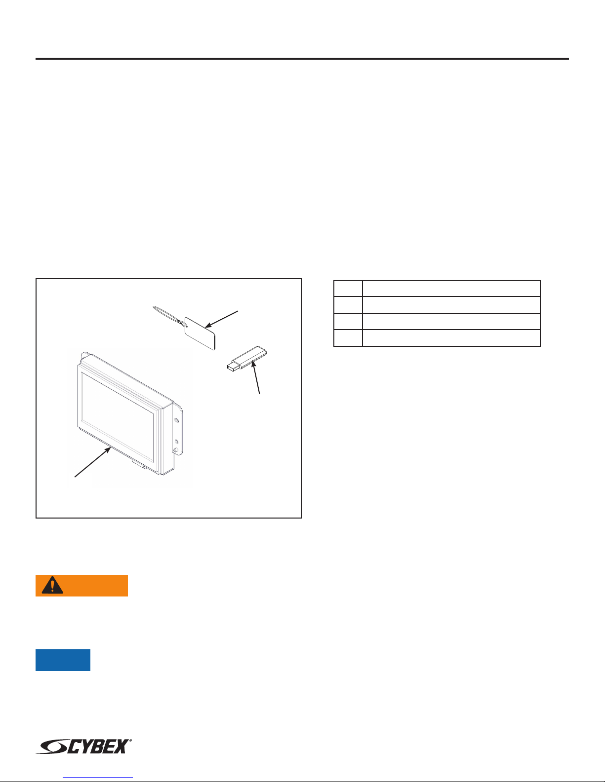
Verify the kit contents shown.
Description
2
1 CardioTouch Screen
2 USB key FOB W-Lanyard
3 USB 2.0 ash drive
1
Disconnect external power source
Unplug the treadmill from the power outlet.
WARNING: Shock and electrocution hazard
• Unplug unit and let sit 10 minutes before cleaning or performing maintenance
• Electrical charge can remain in unit after unplugging
• Keep water and liquids away from electrical parts
NOTICE: Component damage
Wear an ESD grounding strap during this procedure. Connect ESD grounding strap to
frame bolts or unpainted metal of frame. If ESD grounding strap is not available, touch
frame bolts or unpainted metal of frame before handling any electronics.
3
Page 1 of 11
www.cybexintl.com
Page 2
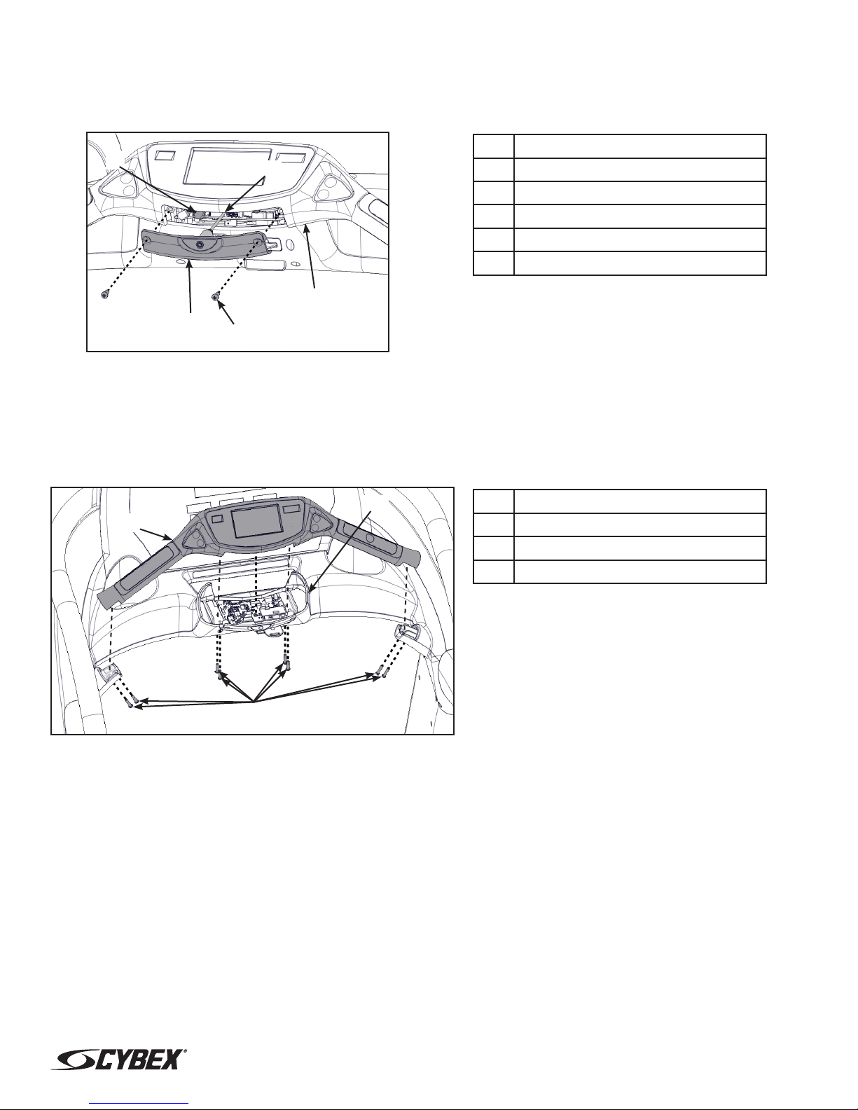
Remove headphone jack
1. Remove the two screws securing the headphone jack cover to the handset using a Phillips
screwdriver.
1
2
1 Connector J6
2 Headphone jack cable
3 Headphone jack cover
4 Screws (2)
5 Handset
5
Description
3
4
2. Unplug the headphone jack cable carefully from the connector J6 on the MCC board
(connector on right). Pull connector straight out, cable uses a 90 degree connector.
Remove handset assembly
1. Remove the eight screws securing the handset to the console using a Phillips screwdriver.
2
1
Description
1 Handset assembly
2 Console
3 Screws (8)
3
Page 2 of 11
www.cybexintl.com
Page 3
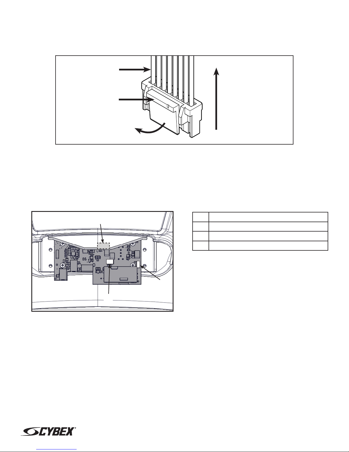
2. Unplug cables by un-latching connector from the MCC board with the following procedure Use
ashlight to locate connector latch and orientation. Note the orientation of the cable connector:
A. Press in the latch of the cable connector.
DO NOT PULL
CONNECTOR OUT
BY THE WIRES!
Latch
Pull Straight Out
From Connector
B. Ensure the latch disengages the connector.
C. Unplug cable by holding down the latch and pulling straight out from the connector. Do not
pull on wires, remove by connector.
3. Carefully lift the handset assembly and unplug the following cables: contact heart rate grips
(J7), handset membrane (J9) and the ground wire (located under the MCC board).
1
Description
1 Graphics Board (J12) (under cover)
2 Handset Membrane (J9)
3 Contact Heart Rate Grips (J7)
2
3
Page 3 of 11
www.cybexintl.com
Page 4
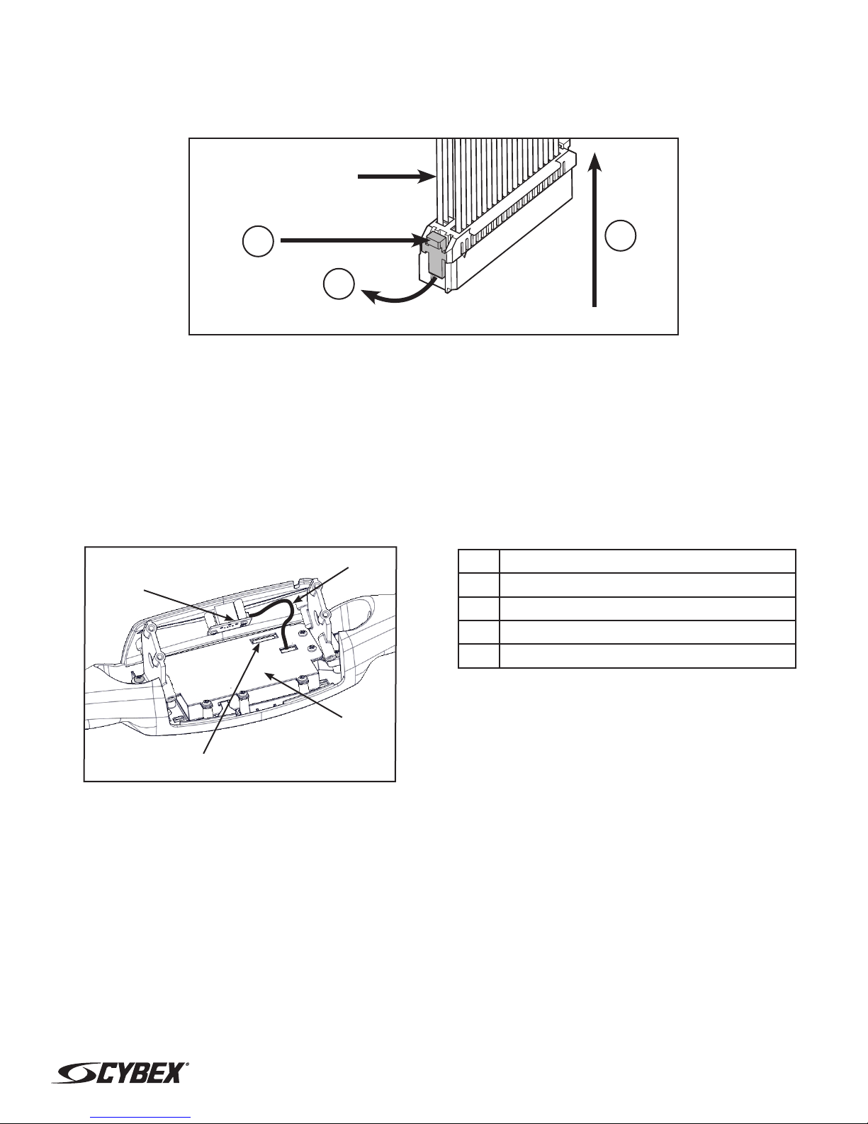
4. Lift the handset assembly carefully and unplug the graphics board cable (J12). The iPod cable
is held in place by a notch in the access cover.
A. Press in both side latches of the cable connector.
DO NOT PULL
CONNECTOR OUT
BY THE WIRES!
A
C
B
B. Ensure the latches disengage from the connector.
C. Unplug cable by holding down the latches on both sides and pulling straight out from the
connector. Do not pull on wires, remove by connector.
Remove CardioTouch screen
Do not scratch front face of handset. Place on clean cloth or other soft surface.
1. Unplug the USB cable from the CardioTouch board.
2
1
Description
1 USB Board
2 USB Cable
3 Graphics Board Cable
4 CardioTouch Board
3
2. Unplug the graphics board cable from the CardioTouch board.
4
Page 4 of 11
www.cybexintl.com
Page 5

3. Remove the two screws and USB cover from the two support brackets using a Phillips
screwdriver.
2
Description
1 USB Cover
2 Screws (2)
3
3 Support Bracket
1
4. Remove the four screws and two support brackets using a Phillips screwdriver.
1
2
Description
1 Screws (2)
2 Support Brackets
3 Handset
1
3
5. Remove the seven screws and ground cable using a Phillips screwdriver.
2
Description
1 Handset
2 Screws (7)
3 Ground cable
1
4 CardioTouch board
3
4
Page 5 of 11
www.cybexintl.com
Page 6

6. Remove the CardioTouch screen and clean the area with a clean cloth and rubbing alcohol.
1
Install CardioTouch screen
1. Place the CardioTouch board in place in the handset.
2
1
Description
1 Clean this area
Description
1 Handset
2 Screws (7)
3 Ground cable
4 CardioTouch board
3
4
2. Install the ground cable with a screw in the location shown and tighten by hand.
3. Install the remaining six screws by hand.
4. Tighten the seven screws in the order shown to 4 in-lbs (0.45 Nm) using a torque screwdriver.
Tighten Screws In This Order
2
4
7
5
6
1
3
Page 6 of 11
www.cybexintl.com
Page 7

5. Install the four screws and two support brackets using a Phillips screwdriver.
1
2
Description
1 Screws (2)
2 Support Brackets
3 Handset
1
3
6. Install the USB cover to the two support brackets using two screws and a Phillips screwdriver.
2
Description
1 USB Cover
2 Screws (2)
3
3 Support Bracket
1
7. Plug the graphics board cable into the CardioTouch board.
2
1
Description
1 USB Board
2 USB Cable
3 Graphics Board Cable
4 CardioTouch Board
4
3
8. Plug the USB cable into the CardioTouch board.
Page 7 of 11
www.cybexintl.com
Page 8

Install handset assembly
1. Place the handset assembly in position and plug in the following cables: contact heart rate
grips (J7), handset membrane (J9), graphics board (J12) and the ground wire. Note the
orientation of the cable connectors.
1
Description
1 Graphics Board (J12) (under cover)
2 Handset Membrane (J9)
3 Contact Heart Rate Grips (J7)
3
2
Ensure the iPod cable is routed through the notch in the access cover.
2. Using a Phillips screwdriver, install the eight screws securing the handset assembly to the
console.
2
1
Description
1 Handset assembly
2 Console
3 Screws (8)
3
Page 8 of 11
www.cybexintl.com
Page 9

Update software
USB stick
NOTICE: Repairs and Service
• DO NOT load zip les onto USB stick
• Load un-zipped les onto USB stick
• DO NOT remove USB stick during upload procedure
• Power must remain on during upload procedure
• DO NOT press any keys on console during upload procedure
Software can ONLY be installed on the model it is designed for. Do NOT install this software on other
Arc Trainers, Bikes, or Treadmills.
Prepare USB stick
1. Plug USB stick into PC.
2. Delete any les on USB stick. Verify USB stick is blank.
3. Please go to the Team Cybex service product pages for the latest software les or contact
Cybex Customer Service at 508-533-4300 to receive via email.
4. Unzip le to a folder on PC. Zip le contains the following les:
• Folder labeled “boot”
• Empty text le with model name of product
• Other single les
5. Copy the “boot” folder and other les to USB stick. DO NOT copy zip le to USB stick.
Perform both procedures for internal and external USB ports.
Page 9 of 11
www.cybexintl.com
Page 10

Install software through internal USB port
1. Remove the two screws securing the headphone jack cover to the handset using a Phillips
screwdriver.
Description
1 Internal USB Port
2 Headphone jack cover
1
3 Screws (2)
4 Handset
4
2
3
2. Insert USB stick into the internal USB port. Do NOT insert USB stick into optional E3 View
Monitor.
3. Plug the power cord into the power outlet. Toggle the power switch on (I).
NOTICE: Console damage may occur
Do NOT turn the power off, press any keys, or remove the USB stick during this
procedure.
The software will load into the console. This procedure will take approximately 3 minutes. During this
time there will be beeping noises from the console. When the upload is complete, the display will
show [re][bot].
4. Toggle the power switch off (0).
5. Remove USB stick from the internal USB port.
Install software through external USB port
1. Insert USB stick into the external USB port.
1
Page 10 of 11
Description
1 External USB Port
www.cybexintl.com
Page 11

2. Toggle the power switch on (I).
NOTICE: Console damage may occur
Do NOT turn the power off, press any keys, or remove the USB stick during this
procedure.
The software will load into the console. This procedure may take up to 4 minutes. During the rst two
minutes the screen will be blank and not show any progress. Do NOT turn the power off, press any
keys, or remove the USB stick.
After the initial period, the screen will display “Loading” and “Please wait”. This procedure may take
up to 2 minutes. When the upload is complete, the display will return to the home screen.
3. Toggle the power switch off (0).
4. Remove the USB stick from the external USB port.
Install headphone jack
1. Plug the headphone jack cable into the connector J6 on the MCC board (connector on right).
1
2
1 Connector J6
2 Headphone jack cable
3 Headphone jack cover
4 Screws (2)
5 Handset
5
Description
3
4
2. Install the two screws securing the headphone jack cover to the handset using a Phillips
screwdriver.
Complete installation
1. Verify the power cord is not being pinched under the front of the treadmill.
2. Toggle the power switch on (I).
3. Operate the unit at all levels to verify proper operation.
Cybex® and the Cybex logo are registered trademarks of Cybex International, Inc.
Copyright © 2013, Cybex International, Inc. All rights reserved • LT-23328-4 C • October 2013
10 Trotter Drive Medway, MA 02053
508-533-4300 • FAX 508-533-5183 • www.cybexintl.com
Page 11 of 11
www.cybexintl.com
 Loading...