


AutoView 200
Installer / User Guide
Supported by
Technology Corporation
Huntsville, Alabama 35805-6201 • USA
256-430-4000 (Fax) 256-430-4030
TM
274 Madison Avenue, New York, NY 10016
Tel: 212-679-0050 • Fax: 212-679-0040
E-mail: Sales@RackitTechnology.com
www.RackitTechnology.com
4991 Corporate Drive
www.cybex.com

AutoView 200 Installer/User Guide

AutoView 200
Installer/User Guide
Cybex Computer Products Corporation
4991 Corporate Drive
Huntsville, Alabama 35805-6201 • USA
(Tel) 256-430-4000 (Fax) 256-430-4030
www.cybex.com
©1999 Cybex Computer Products Corporation. All rights reserved.
IBM, PC/AT and PS/2 are registered trademarks of International Business Machines Corporation. ScrollPoint
is a trademark of International Business Machines Corporation. Expert Mouse is a registered trademark of
Kensington Technology Group. Microsoft, Logitech and Kensington are registered trademarks of their
respective companies. MouseMan, Marble and TrackMan are registered trademarks of Logitech, Inc. Cybex
and the Cybex logo are registered trademarks of Cybex Computer Products Corporation. AutoView,
Commander, LongView, AutoBoot and all part numbers are trademarks of Cybex Computer Products
Corporation. IntelliMouse is a trademark of Microsoft Corporation.

AutoView 200 Installer/User Guide
FCC Notification
Warning: Changes or modifications to this unit not expressly approved by
the party responsible for compliance could void the user's authority to
operate the equipment.
Note: This equipment has been tested and found to comply with the limits
for a Class A digital device, pursuant to Part 15 of the FCC Rules. These
limits are designed to provide reasonable protection against harmful
interference when the equipment is operated in a commercial environment.
This equipment generates, uses and can radiate radio frequency energy
and, if not installed and used in accordance with the instruction manual,
may cause harmful interference to radio communications. Operation of
this equipment in a residential area is likely to cause harmful interference
in which case the user will be required to correct the interference at his
own expense.
Canadian Notification
This digital apparatus does not exceed the Class A limits for radio noise
emissions from digital apparatus set out in the Radio Interference
Regulations of the Canadian Department of Communications.
Le present appareil numerique n'emet pas de bruits radioelectriques les
limites applicables aux appareils numeriques de la class A prescrites dans
le Reglement sur le brouillage radioelectrique edicte par le ministere des
Communications du Canada.

Table of Contents
Chapter 1 - Product Overview
Feature Overview ...................................................................................................................................... 1
Compatibility ............................................................................................................................................. 3
Chapter 2 - Installation
Basic Install ................................................................................................................................................ 5
Advanced Install ....................................................................................................................................... 9
Chapter 3 - Basic Operations
Overview ................................................................................................................................................... 11
Keyboard Control .................................................................................................................................. 12
Keyboard Switching ............................................................................................................................. 13
System Control & Maintenance ....................................................................................................... 14
Chapter 4 - On-Screen Display Operations
Activating OSD ...................................................................................................................................... 15
The OSD Window .................................................................................................................................. 16
The Command Menu ........................................................................................................................... 17
Basic Channel Maintenance ............................................................................................................. 18
The ID Window ...................................................................................................................................... 20
Administrator Functions ..................................................................................................................... 22
Chapter 5 - Advanced Operation
Multiuser Operation ............................................................................................................................. 25
Multi Chassis Operation ..................................................................................................................... 26
Chapter 6 - Channel Scanning
Choosing a Scanning Method .......................................................................................................... 29
Turning Scanning On and Off........................................................................................................... 30
Chapter 7 - Appendices
A: Specifications .................................................................................................................................... 31
B: FLASH Upgrading ............................................................................................................................ 32
C: Troubleshooting................................................................................................................................ 34
D: Problem Report................................................................................................................................. 39
AutoView 200 Installer/User Guide
INSTRUCTIONS: The exclamation point within an equilateral triangle is intended to alert the user to the presence of important operating and maintenance (servicing) instructions in the literature accompanying the appliance.
DANGEROUS VOLTAGE: The lightning flash with arrowhead symbol, within an equilateral triangle, is intended to alert the user to the
presence of uninsulated “dangerous voltage” within the product's
enclosure that may be of sufficient magnitude to constitute a risk of
electric shock to persons.
PROTECTIVE GROUNDING TERMINAL: A terminal which must be
connected to earth ground prior to making any other connections to
the equipment.
POWER ON: This symbol indicates the principle on/off switch is in
the on position.
POWER OFF: This symbol indicates the principle on/off switch is in
the off position.

1
Feature Overview
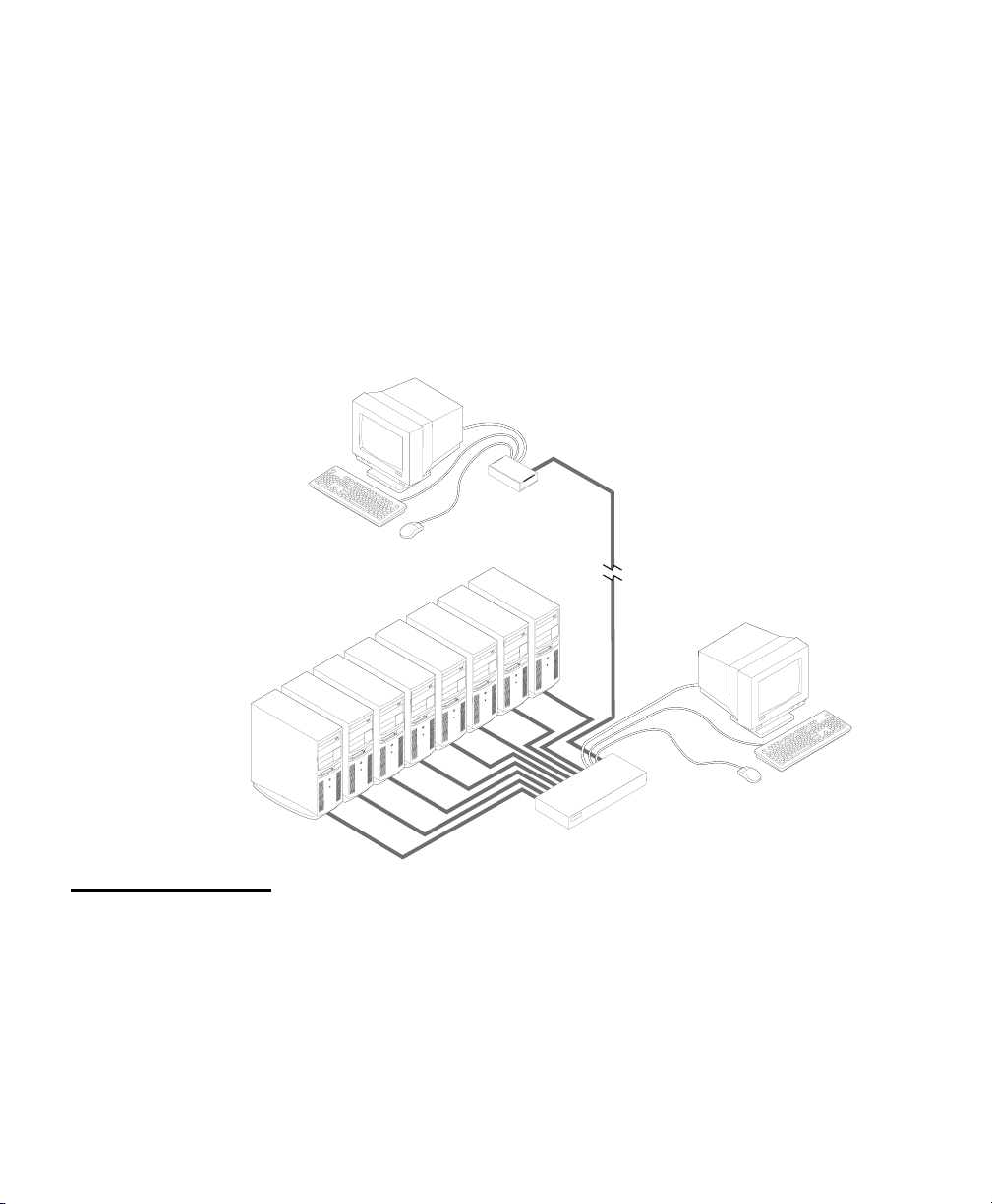
The AutoView 200 allows you to control up to 64 PCs with one keyboard,
monitor and mouse. Each computer can be up to 30 feet away from the
AutoView 200. It also provides you with the added benefit of being able to
add a second user up to 500 feet away from the AutoView system. The
AutoView 200 works with IBM PC/AT and PS/2 systems, and 100% compatible
machines with support for VGA, SVGA, XGA and XGA-II video. PS/2 keyboard
and PS/2 mouse peripherals are supported through the rear of the unit.
Product Overview
Multiuser
capability
FLASH upgrade
capability
Extensive mouse
support
Plug and play
Remote access
capability
The AutoView 200 supports two simultaneous users in the system. Within
the base unit, AutoView 200 performs as a complete 2 x 8 matrix switch,
with both users independently accessing any of the eight attached PCs at the
same time.
The AutoView 200 is FLASH upgradable. This means that you can update
your firmware at any time through a simple serial connection.
The AutoView 200 offers support for numerous mice including: Microsoft
Intellimouse, IBM ScrollPoint, Logitech MouseMan +, Logitech Marble Plus,
Logitech Marble FX and the Kensington Expert Mouse.
The AutoView 200 supports Plug and Play video and is compliant with the
VESA DDC2B standard.
Since the AutoView 200 utilizes a Cybex LongView receiver, your second
user can be as far as 500 feet away from the AutoView 200 unit. Built-in
extension lets you place your second keyboard, monitor and mouse wherever
you need them most.
1

AutoView 200 Installer/User Guide
PS/2 mouse
translation
Expansion for up
to 64 computers
“Keep Alive”
feature
Advanced security
for total control
over system access
On-screen display
capability
For added compatibility with your current equipment, AutoView 200
features PS/2 mouse translation capability. Operated through the
AutoView 200, your PS/2 mouse will work with any attached PC regardless of whether the computer is serial or PS/2 mouse compatible!
An AutoView 200 unit will support from one to eight attached PCs, or
channels. If more than eight channels are needed, multiple units can
be cascaded together for expansion. Up to two tiers of units can be
connected for a total of 64 attached computers in one system.
AutoView 200’s “Keep Alive” feature allows attached servers to power
the unit in the event of an AutoView 200 power failure. This prevents
attached PCs from locking up and keeps you from losing time and data.
Use the advanced multi-level security feature to configure and control
server access for every type of user in the system. The administrator
has full access privileges, while individual users can have viewing or
viewing/editing capability for each attached server.
Configure and control your AutoView 200 with on-screen menuing!
Name your computer channels anything you wish, then select the
desired computer from an easy-to-use menu. Secondary menus let you
configure and initiate channel scanning and other system features.
OSD Configuration
Utility
AutoBoot
technology
Built-in scanning
capabilities
The OSD Configuration Utility allows the administrator to easily
configure and download a channel list with defined users and access
privileges to the entire system. This utility will also read and save your
current configuration for extra security.
The AutoBoot feature boots all attached servers during initial powerup or after a power failure. PCs are booted transparently without
operator intervention, and may be powered-up one-at-a-time or all at
once. When the power stabilizes, a channel may be selected.
A built-in scanning feature allows you to automatically monitor, or
scan, your PCs without intervention. When keyboard activity is
detected, scanning is suspended until all activity stops. Scanning then
resumes with the next channel in sequence.
2
Product Overview
Push-button &
keyboard switching
Status indicator
LEDs
In addition to using the on-screen menus, you can switch computer
channels in one of three easy ways: via the AutoView 200 channel
push-buttons, with the Scan button or with a simple keyboard sequence.
Indicator LEDs give you constant readings on the status of your
AutoView 200 unit. Status, scanning and channel LEDs take the
guesswork out of system operation and diagnostics.
A typical AutoView 200 configuration is shown below.
Compatibility
XGA/XGA-II
support
/
If you wish to use XGA or XGA-II video, you will need to purchase an
adaptor available through Cybex.
3

AutoView 200 Installer/User Guide

2
Basic Install
Basic Installation
1. Power down all computers that will be part of your AutoView
200 system.
Connecting your Local Peripherals
2. Locate your PS/2 keyboard, VGA video monitor and PS/2 mouse.
3. Plug your VGA monitor cable into the port labeled
your AutoView 200. Plug your PS/2 keyboard cable and your PS/2
mouse cable into the ports labeled
PS/2 KEYBOARD CABLE
and respectively.
on the back of
VGA MONITOR CABLE
PS/2 MOUSE CABLE
5

AutoView 200 Installer/User Guide
Connecting your Remote Peripherals
4. Plug a standard Category 5 Unshielded Twisted Pair cable (up to 500
feet) into the RJ-45 style modular jack on the rear of the AutoView 200.
Cybex C5T or Cybex P5T cable is strongly recommended to achieve
best performance and maximum distance. If you use a different
Category 5 cable, make sure it is terminated to the EIA (TIA) 568 B
standard, commonly used for 10BaseT Ethernet.
5. Route the Category 5 cable to the location where you intend to
place the secondary monitor, keyboard and mouse.
6. Place the LongView Receiver near the monitor and connect your
monitor, keyboard and mouse to the connectors on the rear of the
Receiver just as you would connect them to your PC. Make sure you
connect your monitor’s power supply to appropriate electrical outlets.
(Please note that the
not used in an AutoView 200 configuration. Do not connect any-
thing to the
connector on the rear of the Receiver is
connector on the rear of the Receiver.)
7. Connect the Category 5 cable to the modular jack on the rear of
the Receiver.
8. There are two power ports for the LongView Receiver. One on the
back of the AutoView 200 and one on the Receiver. Connect the
circular power plug from the wall mount power supply to either
power port, whichever is most convenient for you. Then plug the
power supply into a convenient electrical outlet. Verify that the
Receiver’s POWER light is now lit.
6
Basic Installation
Connecting Computers to the AutoView 200
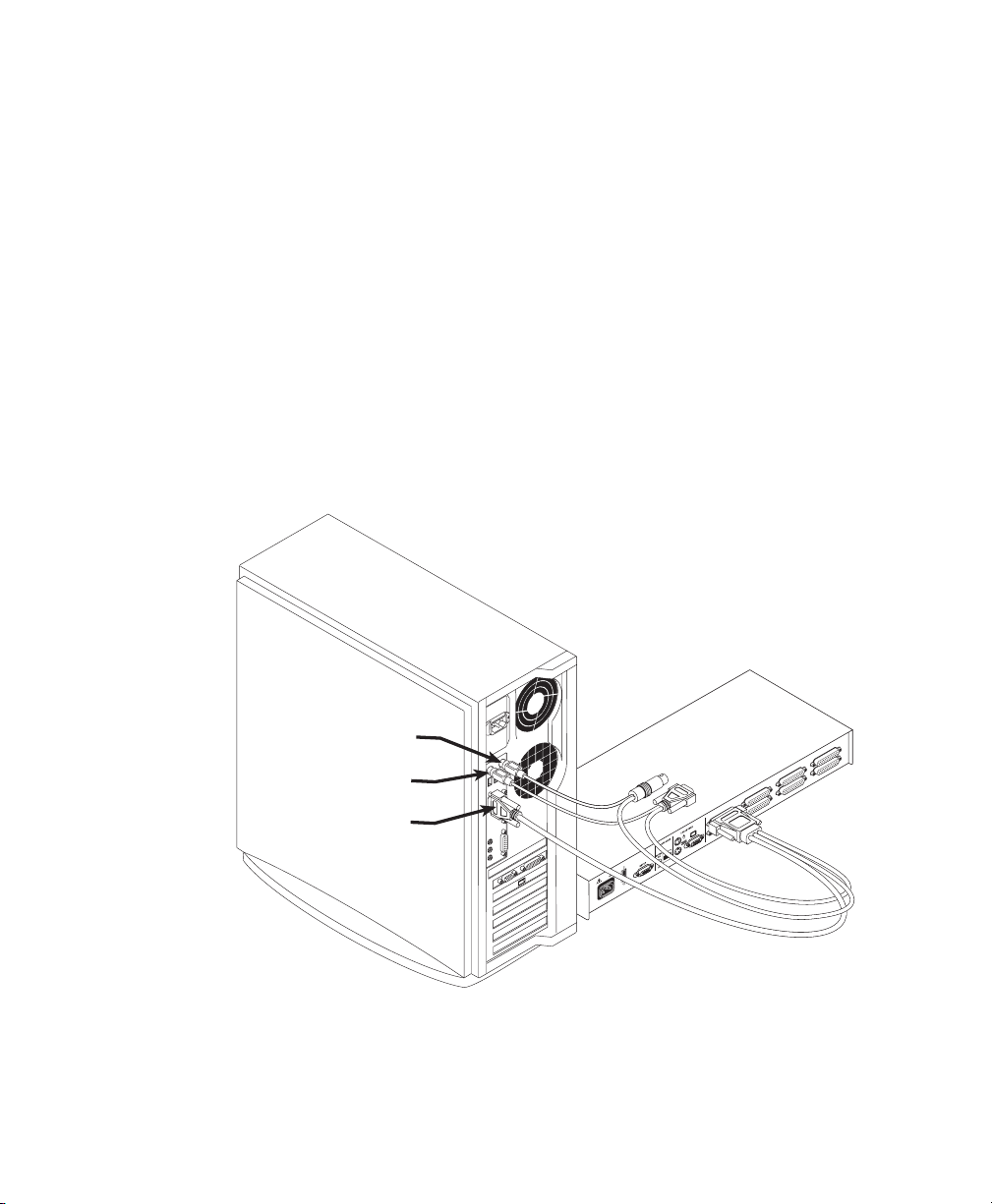
9. Locate your first input cable. It will have a 25-pin “D” connector at one
end. Plug this cable into any lettered channel port on the rear of the
AutoView 200. The other end of the input cable will have five
connectors: a 15-pin “HDD” connector for your video, a 5-pin DIN/6pin miniDIN connector for an AT or PS/2 keyboard connection, and a
9-pin serial/6-pin miniDIN connector for a serial or PS/2 mouse
connection. The PS/2 mouse connector is designated by a yellow band
or mouse icon.
Use only the keyboard and mouse connectors that are appropriate for your PC, and leave the others unconnected.
Plug these connectors into the matching ports on your computer.
PS/2 KEYBOARD CABLE
PS/2 MOUSE CABLE
VGA MONITOR CABLE
POWER
100-240V~, .1a, 50/60Hz
FDB
H
10. Locate your next input cable. Repeat step 9 until all computers are
properly attached to the AutoView 200.
7
AutoView 200 Installer/User Guide
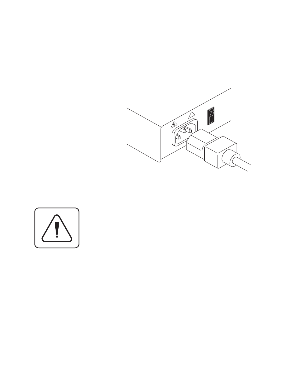
11. Locate the power cord that came with your AutoView 200 unit. Plug it
into the IEC power connector on the AutoView 200. Make sure that the
power switch is off, then plug the other end of the power cord into an
appropriate AC wall outlet. This outlet must be near the equipment
and easily accessible to allow for unplugging prior to any servicing of
the unit.
12. Power-up your AutoView 200 unit first, then power up all
attached computers.
1
!
0
100-240V , .1A, 50/60 Hz
The AutoView 200 and all attached computers should be
powered-down before servicing the unit. Always disconnect the power cord from the wall outlet.
8
Advanced Install
Basic Installation
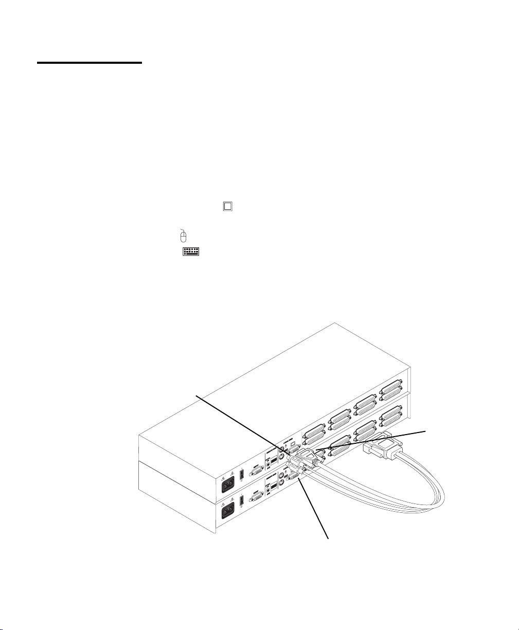
Attaching Multiple AutoView Units
1. Follow steps 1-9 of the Basic Install section for each cascaded unit.
2. Plug the 25-pin “D” connector of your input cable into any available
channel port on the rear of your base AutoView unit.
3. Plug the 15-pin video connector on the other end of the cable into
the port labeled
PS/2 mouse connector, designated by a yellow band or mouse icon,
on your first cascading AutoView unit. Plug the
into the
into the
port. Plug the remaining 6-pin miniDIN keyboard connector
port. The 9-pin serial and 5-pin DIN connectors are not
used for cascading.
4. Repeat steps 9-12 in the ‘Connecting Computers to the AutoView
200’for each attached compter.
PS/2 MOUSE
CONNECTOR
100-240V~, .1a, 50/60Hz
100-240V~, .1a, 50/60Hz
FDB
H
FDB
H
POWER
POWER
CASCADING
UNIT
BASE UNIT
VIDEO
CONNECTOR
PS/2 KEYBOARD CONNECTOR
9
 Loading...