

Page 1

ENGLISH
ENGLISH
CyberView
X5-MS
User’s Man
ual
1
Page 2

Page 3

FEDERAL COMMUNICATIONS
This Equipment has been tested and found to comply with the limits for a class B digital device,
pursuant to Part 15 of the FCC rules. These limits are
against harmful interference in a
radiate radio
may
cause harmful interference to radio
interference will not occur in a particular installation. If
interference to radio or television
off and on, the user
following measures:
frequency
is
encouraged to try to correct the interference by one or more of the
energy and, if not installed and used in accordance with the instructions,
COMMISSION
residential
communications.
reception,
(FCC)
designed to
installation. This equipment generates uses and can
this
which can be determined by turning the equipment
STATEMENT
provide reasonable protection
However, there is
equipment does cause harmful
no
guarantee that
• Re-orient or relocate the receiving antenna.
• Increase the separation between the equipment and receiver.
• Connect the equipment into an outlet on a circuit different from which the
receiver is connected to.
• Consult the dealer or an experienced radio/TV technician for help.
Warning:
Use only shielded signal cables to connect I/O devices to this
cautioned that changes or modifications not expressly approved by
responsible for compliance could void your authority to operate
equipment.
the
the equipment.
You are
party
Page 4

Page 5

ENGLISH
TABLE OF
Getting Started
CONTENTS
2
Quick Installation Guide (QIG)
Installing Scanning Software 3
Installing Hardware
General Information 4
Loading the slides into the Magazine 4
Loading Slides into supported aftermarket trays 5
Loading the Magazine into the Scanner 7
Additional H a rdw a re Features 9
One Button Scan 9
Backlit slide viewer 9
How to Scan Slides
STEP 1 - Acquire Driver
STEP 2- Select Film Type
STEP 3 - Optional Prescan 10
STEP 4 - Set Scan Settings
STEP 5 - Set Scan Preferences
3
3
10
10
10
11
12
STEP 6 - Scan 14
STEP 7 - Exit 14
Scan to Online Sharing Service 15
Facebook 16
Dropbox 18
User Interface 19
I Main Window Area 19
II Preview Window Area
III Active Frame Setting Area 28
IV Thumbnail Panel Area 29
Scan DPI Settings - Additional Information 30
Tips for Hassle Free Scanning 31
Removing jammed slide from the top access door 34
Technical Support
1
26
34
Page 6

needs.
started.
CD.
GETTING
Check the package content before getting
For Quick Installation please refer to Quick Installation Guide. (Ref. Pg. 6)
Package
Slide
50 Slide
Power
STARTED
Important! Save the original box, receipt and packing material for
future
shipping
Contents
Scanner
USB
Cable.
CyberView Scanning Application & Hardware Driver
Magazine
Adapter (could come in 2 pcs)
Warning!
Using any other power adapter o r sli d e t r a ys may severely
damage the
NOTE: The orange adapter on the transport arm and the arm itself are
GENERAL
Connect the scanner
Do not use a hub or USB extension cable. Only use the USB ports on
the
rear
If there are any other devices (multifunction device, printers,
webcam) connected to the computer through USB, disconnect o r
p o we r
A minimum of 2GB RAM (Win/Mac) is
Note: Do not turn on the scanner unless it is within this range. If
Note: If the scanner is stored or to be transported in cold
has been stored or transported outside of this
brought into a warm / humid
This device is designed solely for private use and is not intended for
scan
ner and will void the product
excluded
GUIDANCE:
of desktop
them off.
Operating Ambient Humidity Range 15% to 76%
from
guarantee.
directly using the USB
computers.
Operating Ambient Temperature
50º to 104ºF (10º to
within this range before turning it
Relative
humidity
required.
(non-condensing)
environment
cable provided.
40ºC)
condensation may
range,
warranty
Range
allow it to
on.
temperature
.
scanners,
the
scanner
return
and then
occur.
commercial
to
use.
2
Page 7
QUICK INSTALLATION GUIDE
(QIG)
INSTALLING - CyberView X5- for PC (Windows) User
a. Insert CD into the computer CD/DVD drive and explore the
3
of 38Double click the ”CyberView” icon to begin the installation process.
onscreen prompts to complete the installation
NOTE: Make sure the scanner is NOT connected to the computer during the
CyberView
b. Restart computer once the installation process is
Installing the
a. Connect the slide scanner to a power
with the CyberView X installation process.
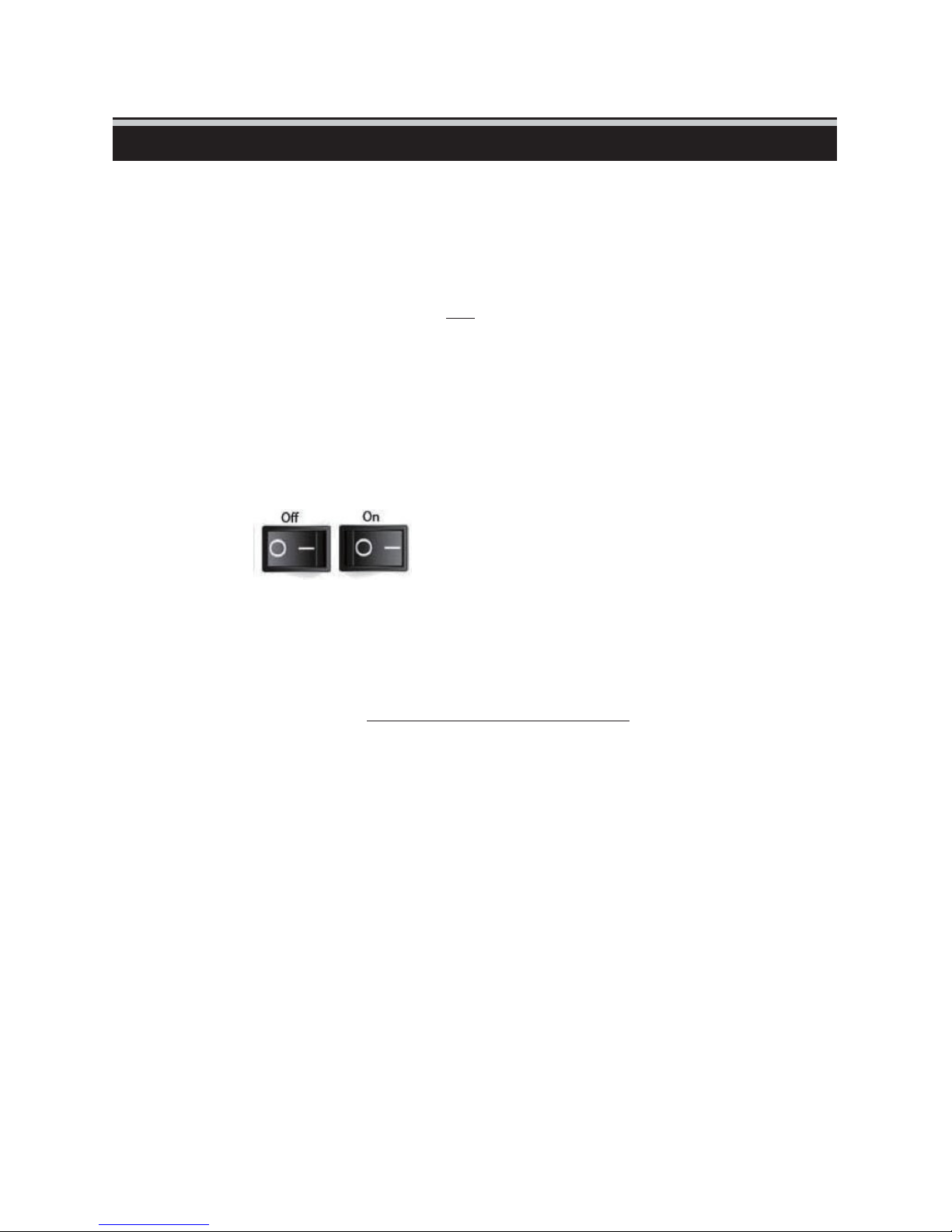
1. Locate the power switch on the lower left side of the scanner. Make
scanner is TURNED
driver
installation.
Hardware
OFF.
process.
source. The hardware drivers automatically loaded
contents of the CD. Page
complete.
Follow
sure
the
the
Circle in OFF / Line in ON
2. Plug the AC adapter into an AC power source FIRST before plugging
WINDOWS SYSTEMS INSTALLATION: DURING DRIVER INSTALLATION A WARNING DIALOGUE BOX MAY
APPEAR, IF THIS IS THE CASE PLEASE SELECT “INSTALL THIS DRIVER ANYWAYS”.
NOTE: Not all PC’s will display the found new hardware window, most will install in the background
Should it occur (Generally on XP/Vista systems) follow the steps below
1. Then In the “Found New Hardware Wizard” window, select “Search automatically or Browse computer for
driver software.”
2. Next In “Completing the Found New Hardware Wizard” window, Click “Finish” to finalize the hardware
installation.
3
scanner.
3. Attach the USB cable to the computer using the standard USB
Attach the USB adapter end of the cable to back panel of the
b. Ensure the scanner does NOT have a slide magazine loaded, turn the
The calibration cycle on the scanner will start automatically and will
minutes to complete. A green light will flash while the calibration is
The slide transport arm will move in and out of the scanner.
ENOUGH ROOM IN FRONT OF THE SCANNER FOR THE
EXTEND FULLY; DO NOT PUSH THE ARM BACK
it
into the
adapter
scanner.
MAKE
SURE THERE IS
SLIDE
TRANSPORT ARM TO
DURING CALIBRATION.
scanner
take
several
in
progress.
end.
ON.
Page 8
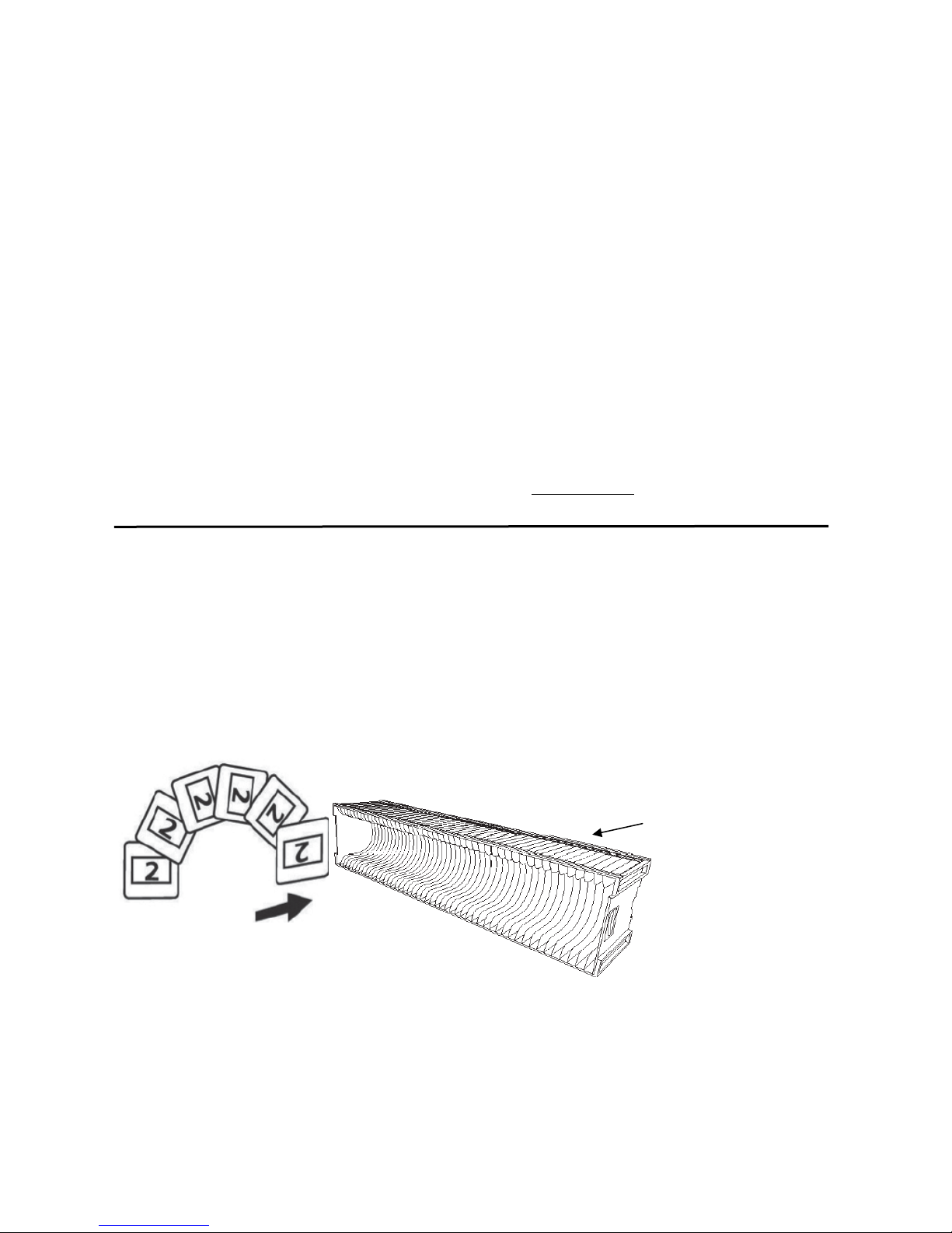
General
#2 on the slides
in this drawing represents the emulsion
ALL Trays:
Information:
Load slides with the SHINY side facing the right side of the tray, this will result in a backwards
scanned image, but due to the hardware design this is necessary to obtain the best scan quality.
Supported Slide Trays:
Braun Paximat S (White tray) and PIE Dark gray tray (bundled) designed for thicker cardboard
mounted slides 2 - 3.2mm thickness.
Paximat Compact Magazine (Black tray) for mounted slides up to 2mm thickness, plastic and thin
cardboard mounts.
CS Magazine for CS/CS2-mounted slides (European design
Universal Magazine DIN 108 (open top design) for slides up to 3.0mm thickness
KLM Magazine for slides up to 2mm thickness
NO OTHER BRANDS OF TRAYS OR CAROUSELS SUPPORTED
Glass slides that are attached to glass frames may cause complications due to the hard edges and
thickness, nothing thicker than 3mm can be scanned.
Metal slides: Cardboard slides mounted into metal frames, not supported, they MUST be un-mounted
Loading slide(s) into the
Gray Magazine
a. Locate the numbering sequence text on the top of the slide
up and
b. Hold the slide right side up, facing forward so the image
is
and Insert each
Essentially they will be inserted upside down and backwards, they will require flipping
in an image editing program
WARNING: Load slides into the magazine properly and make sure the slide mounts are in
Improperly inserted slides or slides with
to jam and potentially damage both the slide and the
magazine(s)
or Paximat S
maga
zine indicating the slide order. The numbers should be facing
starting
NOT
reversed. Rotate the slide as illustrated below (180 deg)
from the
slide,
Magazine (white)
left.
one at a time, into the
magazine slots.
Paximat
Magazine
distorted/damaged
slide mounts may
scanner.
Numbering
good
cause
condition.
the scanner
4
Page 9
ENGLISH
Loading slide(s) into aftermarket
magazines
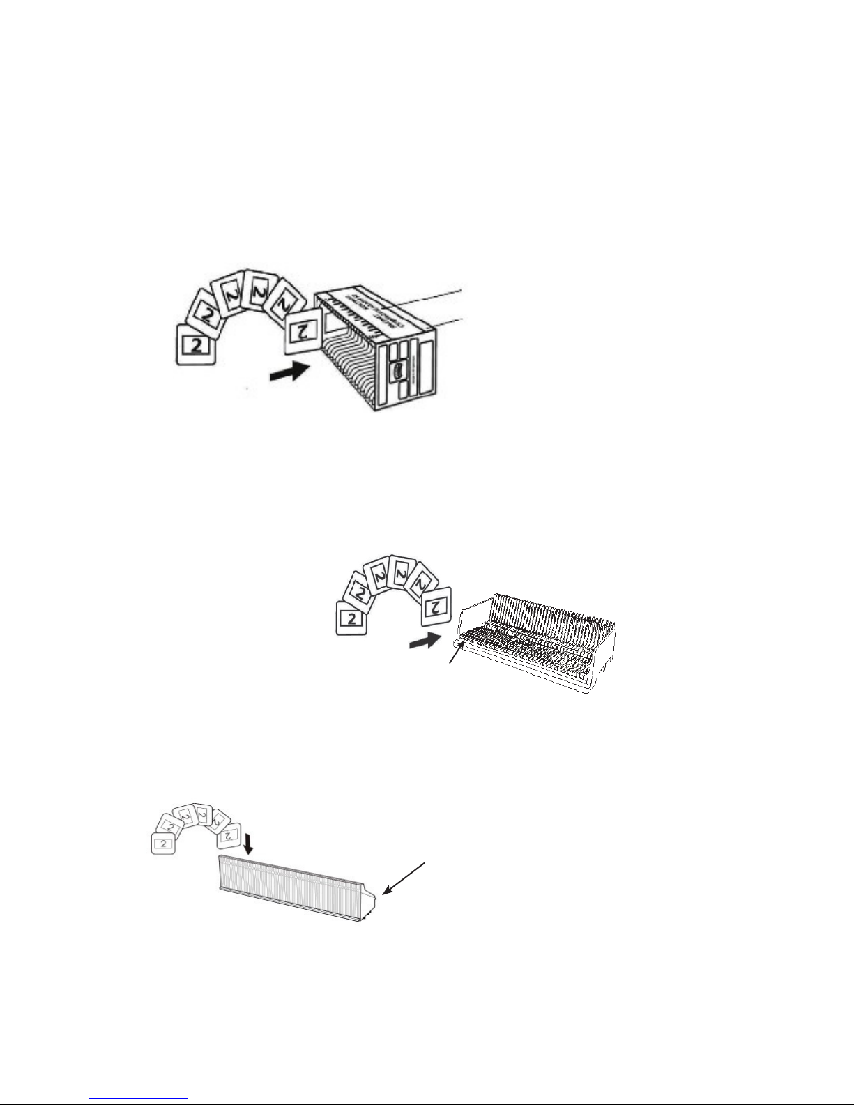
Paximat Compact Magazine (1.8-2.0mm slides)
a. As illustrated below, turn the magazine with the embossed lettering
MAGAZINE 50” and the white strip on the right facing towards the
b. Hold the slide right side up, facing forward so the image is NOT
Rotate the slide as illustrated and Insert each slide, one at a time, into
magazine.
“COM
top.
reversed.
the
PACT
Lettering
Compact Magazine
White
Strip
CS
Magazine (European)
a. Locate the numbering sequence text on the CS slide magazine indicating
the
slide order. The numbers should be facing up and starting from the
l
eft.
b. Hold the slide right side up, facing forward so the image is NOT r
eversed.
Rotate the slide as illustrated and Insert each slide, one at a time, into
the magazine.
CS
Magazine
Num bering
LKM
Magazine (US & Europe)
a. Locate the numbering sequence text on the front of the LKM
slide
magazine indicating the slide order. The numbers should
be
facing
forward and starting from the
right
b. Hold the slide right side up, facing forward so the image is NOT
re-
versed. Rotate the slide as illustrated below (180 deg) and
Insert
each
slide into the slots, one at a time, into the
magazine.
Numbering
5
Page 10
Loading slide(s) into aftermarket magazines
cont…
Universal
Magazine - DIN 108 (US & Europe –open top design)
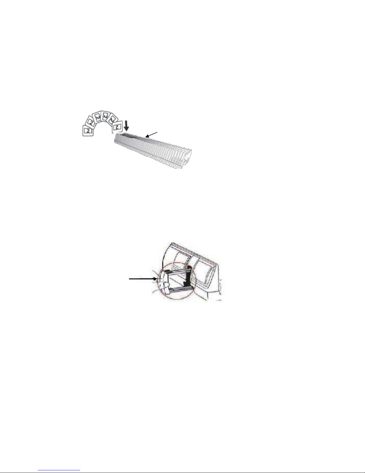
a. Locate the numbering sequence text on the top of the
Universal
numbers should
b. Hold the slide right side up, facing forward so the image is
slide magazine indicating the slide order. The
be
facing up and starting from the
left.
NOT
reversed. Rotate the slide as illustrated below (180 deg) and
Inser t
each slide, one at a time, into the
magazine.
Numbering
NOTE: For all magazines (except the Universal Magazine)
If the Universal tray (DIN 108) was previously used - Return the orange adapter to its original position at
the grip of the slide transport arm after scanning. To release the adapter, gently press its outer tip.
a. Remove the dust cover from scanner exposing the slide magazine loading area.
b. Load the magazine into the scanner as illustrated on the following pages.
Slide Transport “Tappet” Arm
Orientation of scanner in these diagrams is viewed from the back of the unit.
Take note that the magazine slide opening also faces towards the back of the scanner for correct
orientation when loading into the scanner.
6
Page 11
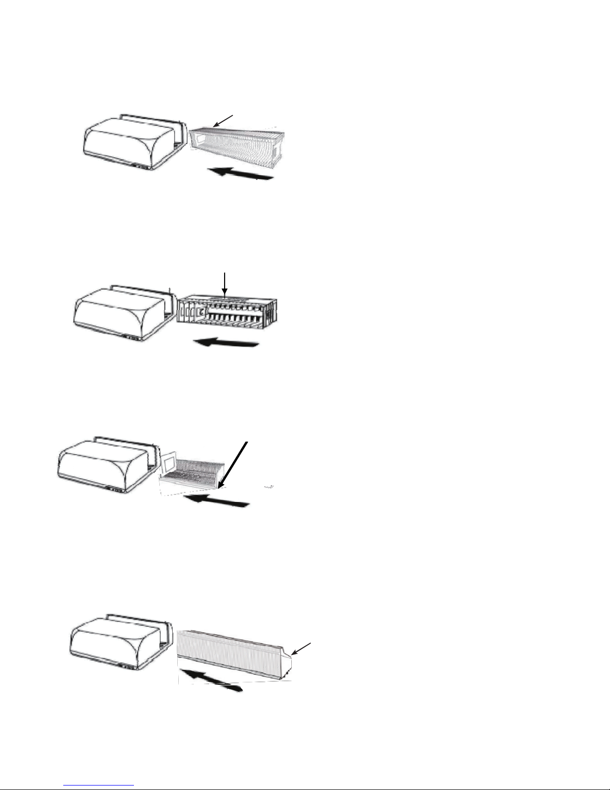
Loading the magazine(s) into the scanner
Numbering
Numbering
Numbering
Paximat/Bundled
Slide order numbers printed on top of
Magazine
magazine
large opening you load the slides into faces the back of
the device., This tray needs to be level otherwise it will
not insert and appear to be blocked by a small black tab
on the bottom of the tray area, if it hits this the tray is
not level, it needs to guide in straight and touch the
“Slide Transport” Tappet scanning arm
Compact
Insert with the Embossed
and the
the
Magazine
white
scanner.
letters facing up
stripe near the front panel of
CS
Magazine
Slide order numbers printed on
magazine facing
the
scanner.
towards the back of
LKM
Magazine
Turn the slide tray around so the numbers face the
front of the device and the open slots face the back,
before
inserting
Numbering
7
the
Page 12
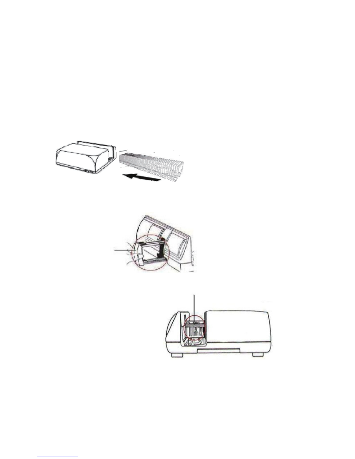
Universal Magazine
NOTE: Use only Universal Magazines with the DIN 108 labeling. Other magazines may result in problems and
could damage the scanner and VOID the warranty.
Pull out the slide transport arm all the way, gently press the orange adapter on the slide transport arm, move the
adapter on the slide transport arm to the front until it snaps in at the tip of the tappet arm.
Push the slide transport arm back into the scanner.
Load the magazine from the back in the respective guiding rails of the
slide transport
arm.
Universal
Magazine
Slide order numbers printed on top of
the
right hand side of
the
scanner when l
magazine
oading.
maga
zine tunnel until it touches the
magazine
on
towards the front of
Universal “DIN 108” Tray
c. Place the slide magazine into the scanner from the left side until it
touches
place.
Slide Transport Arm
the slide transport arm and the magazine “clicks” into
Slide tra y h
older area
8
Page 13
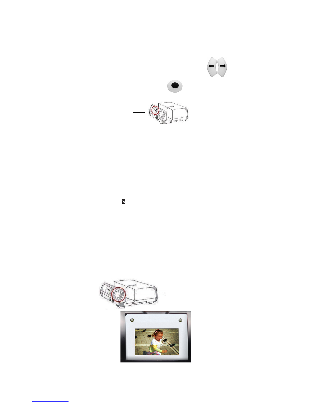
Additional hardware features….
Manual Control Panel
Manual Fron t Control
a. You can advance or reverse the slide tray by pressing the navigation
or scan manually using the scan button to perform one button
scanning, CyberView X must be open to use this button.
Please Note: When installing your new scanner onto a Windows system that
already has another USB Flatbed scanner or All-in-one
device installed, it may be
the other scanner from the USB port for the Film scanner to work
One Button
1. Open the CyberView X application (Ref. page 16 to acquire the CyberView software)
2. Configure Scan Settings (see Page
Configure the scan settings: Select the Scan to directory, file format
(TIF or JPG) Magic Touch/Auto Color etc., once configured, Press
scanner button ( ) to begin
NOTE: If you do not open CyberView FIRST, the scan button will not
c. Slide
The scanner has a built in mini light panel which allows the slides to
be
man
for
scanning.
Insert the slide into the slide viewer for previewing. The scanner has
to
be
engage the
Panel
– Push buttons on the front of the scanner
Scan/Copier/Printer
necessary
for you to power off or even disconnect or
properly,
Scan
17)
the
scanning.
function.
Viewer – Backlit slide viewer (Not scanning display)
ually previewed with a backlight before inserting into the tray
switched on. Gently press down on the top of the slide to
back
light for viewing the
slide.
Mini Light
Panel
buttons
9
Page 14
Pre-S
canning
should
be
used to manually
adjust
color/
crop area,
HOW TO SCAN
SLIDES
STEP 1 – Acquire
(For PC
Driver
Users)
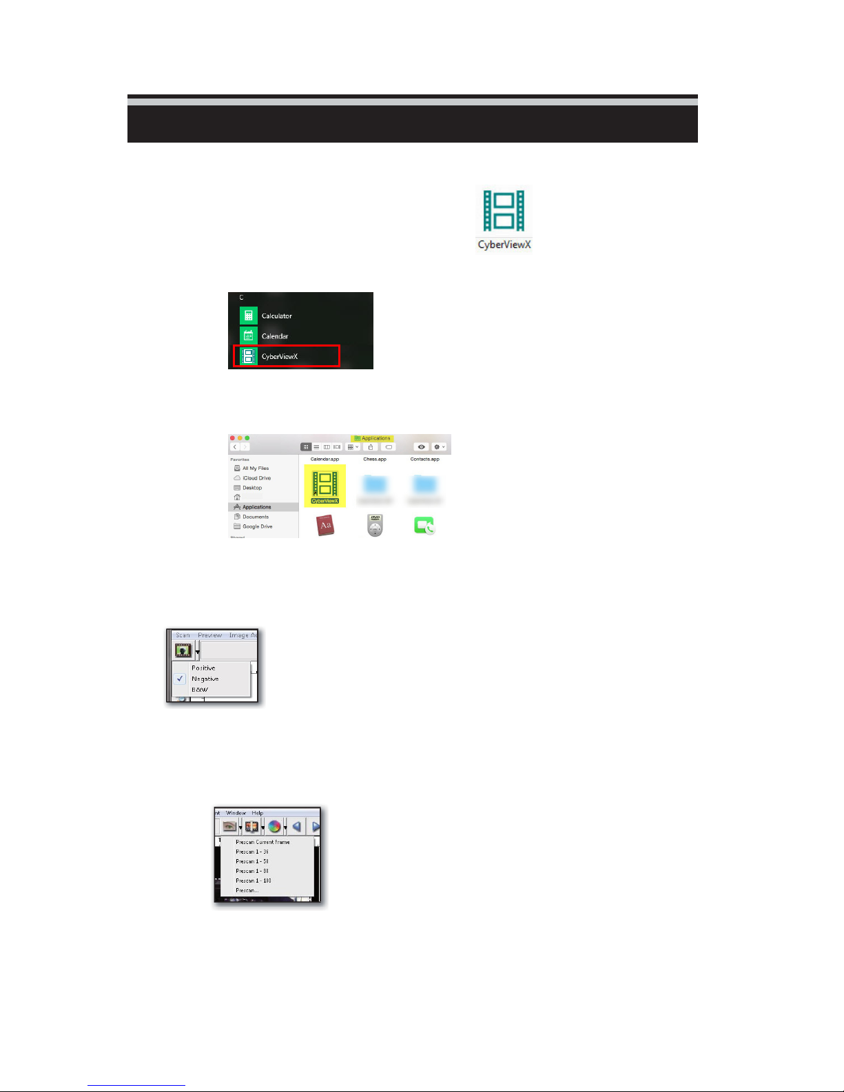
Open CyberView from the d esktop icon
Alternatively Start button Scroll to the letter C category look for CyberView X
Vista/XP - Start – All Programs –
CyberViewX
(For MAC
Open Macintosh Hard drive – Applications –
Users)
CyberViewX
STEP 2 – Select Film
Type
Select the film type to be scanned – Positive (Slides), Negative (mounted negatives) or
mounted B&W negatives (Black and
White).
STEP 3 – Optional
Prescan
Select the “Prescan Current Frame“ to prescan the slide currently
loaded
specific positions in
into
the scanner or “Prescan...“ to prescan slide or slides at
the magazine.
exposure settings etc. for each
possible to set different settings for each slide
Please note
can put a lot of wear and tear on already decaying slide mounts,
pre-scan is ONLY required if you plan to pre-edit all or some of the
images manually before final scanning, otherwise use the available
automatic correction features to do it for you, and skip
prescanning altogether
: With older cardboard mounts the optional Pre-Scan
slide
before doing the final scan. It’s
to
be
scanned.
10
Page 15
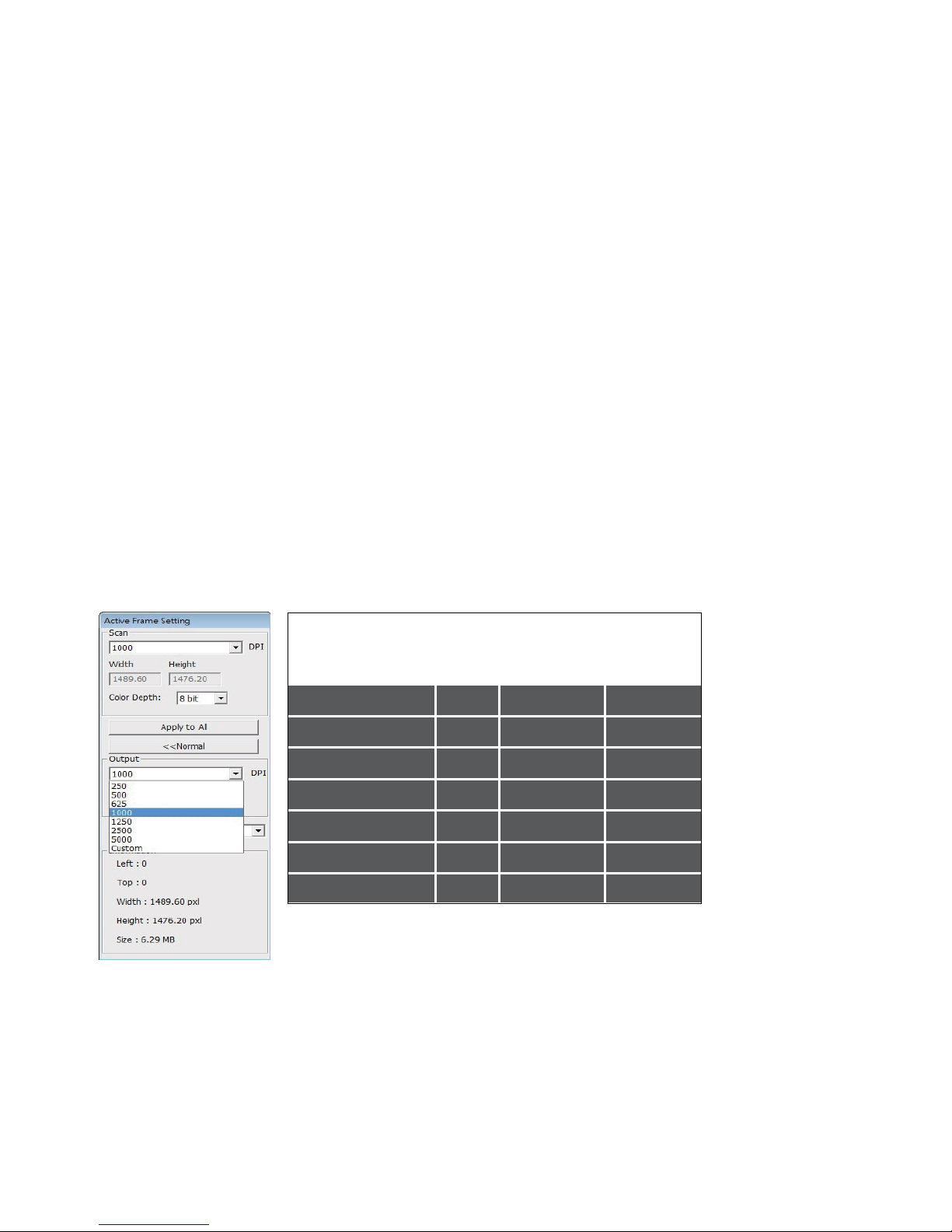
STEP 4 – Set Scan
a.
Resolution (Scan dpi)
Settings
The default scanning resolution is 1000dpi, additional resolution
options
are listed
below.
Notice: Higher scanning resolutions result in greater scanning time
and
hard disk
space
requirements.
Examples of resolution to use:
Here are the minimum resolutions to display slide shows on an HDTV with high quality
1080p TV = 1500 dpi minimum to achieve a 1920 x 1279 pixel image,
4K TV = 2840 minimum to achieve a 3840 x 2558 pixel image, 4K TV resolution is 3840 x 2160
8K TV = 5700 minimum to achieve a 7730 x 5113 pixel image, 8K TV Resolution is 7680×4320
(for additional resolution information regarding printing see page 30)
b. Color
The Film Scanner color depth is 48 bit true
The scanning software has the capability of selecting 8 bit color mode or 16
color mode when scanning, This will produce 24 or 48 bit color images, 8
or 16 bits per Red, Green and Blue color
Depth
color
bit
bits
channels
Example:
8 bit mode = 8 Red, 8 Green, and 8 Blue for a total of 24 bit
16 bit mode = 16 Red, 16 Green, and 16 Blue for a total of 48 bit
color
color
Note: Color image file size of different resolutions and color
depths:
Scanning Resolution
300dpi 8 bit 24-bit ~370Kb
Color
Depth (by
RGB
Channel
Color Mode
File Size TIFF (no
compression)
600dpi 8 bit 24-bit ~1.4MB
1800dpi 8 bit 24-bit ~12.9MB
3600dpi 8 bit 24-bit ~52MB
5000dpi 8 bit 24-bit ~100MB
7200dpi 8 bit 24-bit ~208MB
10000dpi 8 bit 24-bit ~402MB
Scans include Auto Balance and Digital
Processor: AMD 9650 Quad-Core
Reduction
Memory :
System type: Vista 64
2GB
on:
bit
2.3GHz
Noise
Scan Mode – Normal: Produces a scan in jpeg format
Quality Mode- pro
duces a
non-compressed,
“loss-less” TIFF
image.
11
Page 16
ENGLISH
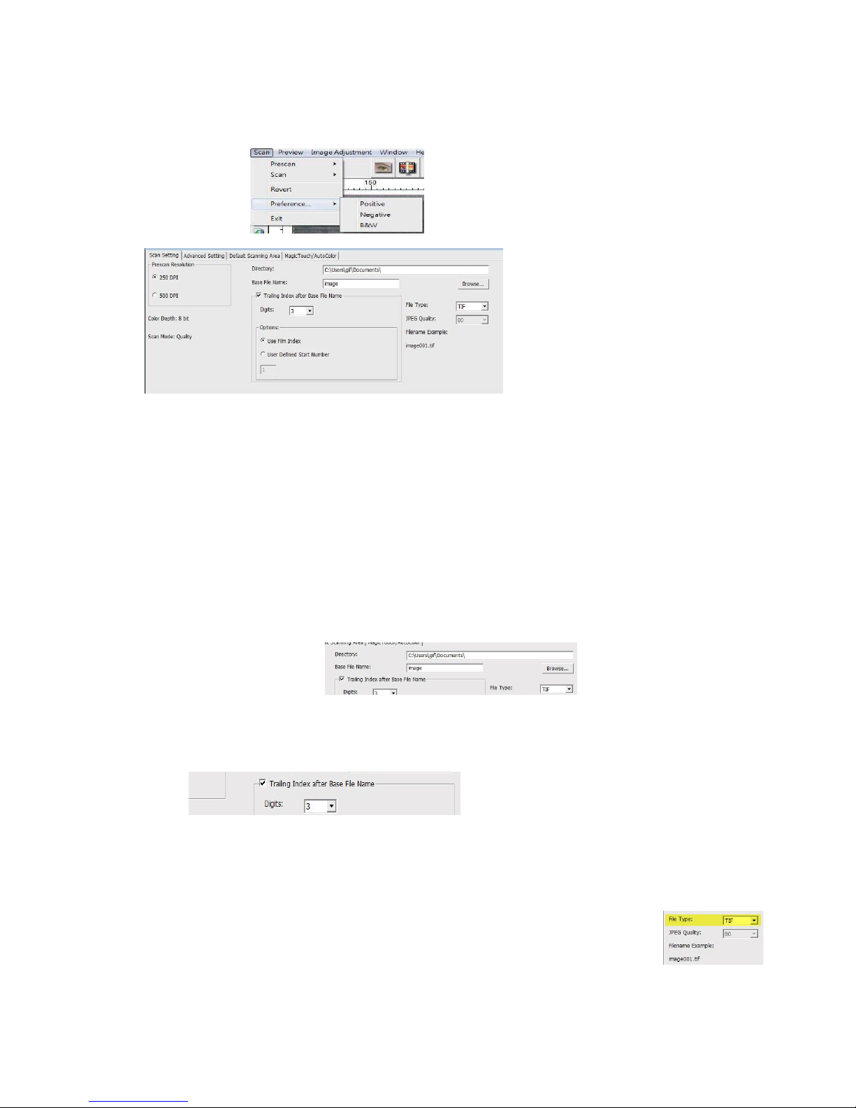
STEP 5 – Setting Scan
Select Scan - Preference - Positive - Scan
(Negative and B&W options are only for negative strips that have been cut and mounted into slide holders))
Preferences
Setting
“Prescan Resolution“ - Default pre-scan
resolution, if you select the optional prescan to pre-edit slides before scanning the higher the pre-scan resolution the larger
sample you have to work with for pre-editing before the final scan..
(Please note with older cardboard mounts the optional Pre-Scan can put a lot of wear and tear on
already decaying slide mounts, pre-scan is ONLY required if you plan to pre-edit all or some of the
images manually before final scanning.)
“Color Depth“ – 8 bit (24bit) or 16 bit (48bit) Default color depth
“Scan Mode“ – Default scan mode while
normal is for standard slide images
scanning. Quality mode is for x-rays, medical slides etc.,
Configuring Scan
settings
1. Select Browse and choose the designated folder to save the
scanned
image to
2. Enter the file name.
3. Trailing Index after Base File Name Digits X: Defines the length of the
file
name and numbering sequence up to 6 digits Example D igits 3 (Def aul t )
r esul ts i n a f i le na m e i ma ge 0 01 by se l ect i ng d igi t s 1 -6 yo u r f i le name w i ll
c han g e a c cor d ingly
4. Options - Use Film Index: Use the number assigned to the
slide based on
User Defined Start Number: Enter a specific start
keeping track of your own sequential scan numbers
5. Choose the file type, “TIF” or “JPG”. (TIF un-compressed or JPG
Compressed -
offers the least amount of
outputs to an 8bit formatted image even when scanned using 16bit mode
12
image000001.
its
position in the
cartridge.
Choose image quality for JPEG. (20-100) 100
compression, best quality, JPG only
number, better for archiving and
Page 17
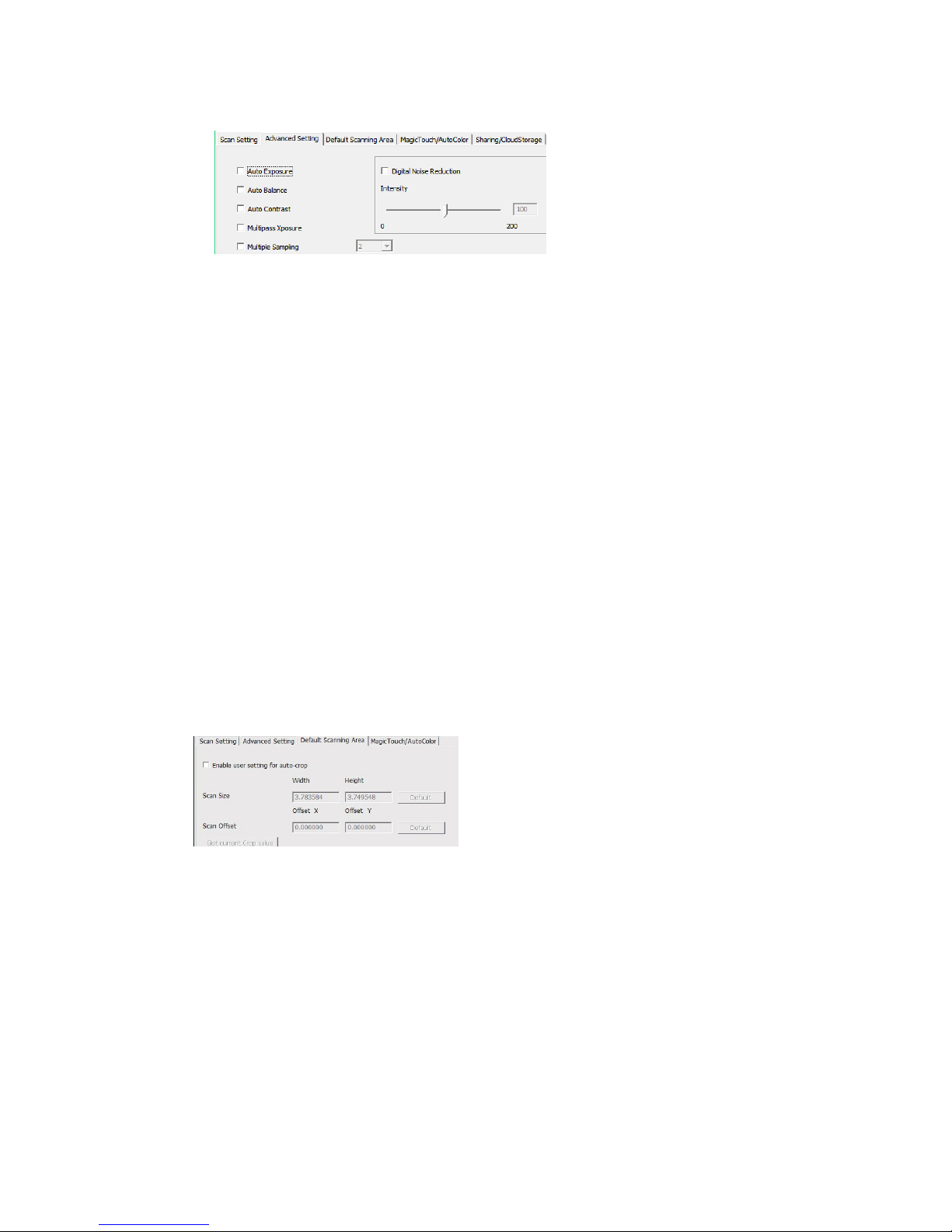
Advanced
Settings
”Auto Exposure” - Attempts to find the correct exposure to get
the
widest
grays at around
range of whites and blacks while putting the middle
the
middle of the data
”Auto Balance” - Using the image histogram to balance RGB
channels.
accordingly
It
estimates images’ color cast and adjust the images
“Auto Contrast” - The scanner software analyzes the data and
automatically
”Digital Noise Reduction” – Applies a filter, reducing the film
adjusts the Setting for the White and Black
”Multipass Xposure” - When enabled multi-exposure performs a triple scan to
obtain the best possible image, this process captures the three individual scans, first
a normal pass then two more scans to highlight the shadow details to expose the
darker areas more fully,
the software then intuitively calculates the final scan, which now contains the data
from all three scans.
”Multiple sampling” - Configure the settings to scan a single image (multiple times)
2x, 4x, 8x or 16x for the highest quality output. Please note this greatly increases scan
time. With multisampling image noise is a thing of the past.
(Multi Sampling will greatly increase the scan times for each slide)
Default Scanning Area
Adjust the scanning size as well as adjust the “Scan Offset” setting to move
the image position of slide.
Magic Touch / Auto
Enable / disable Magic Touch and Auto Color adjustment
Magic Touch I s a powerful dust and scratch removal technology that does
away
with the hassle of learning complex and tedious software techniques.
Being hardware-based,
the best
scratches
the image
possible results when bringing images into the computer. Dust,
and other flaws are intelligently detected and eliminated, restoring
to
its original
Color
it works seamlessly with the scanning process to ensure
beauty.
Scanning with Magic Touch requires longer scanning times, the feature is turned
off by
default.
Auto Color takes the guesswork out of the scanning process to streamline the
workflow and achieve the best results. Proprietary color
applied to scanned images to provide the most accurate
vibrant images with optimal brightness, contrast
range.
Points.
grain.
to scans.
enhancement
color
adjustment, resulting in
technology is
and saturation.
13
Page 18
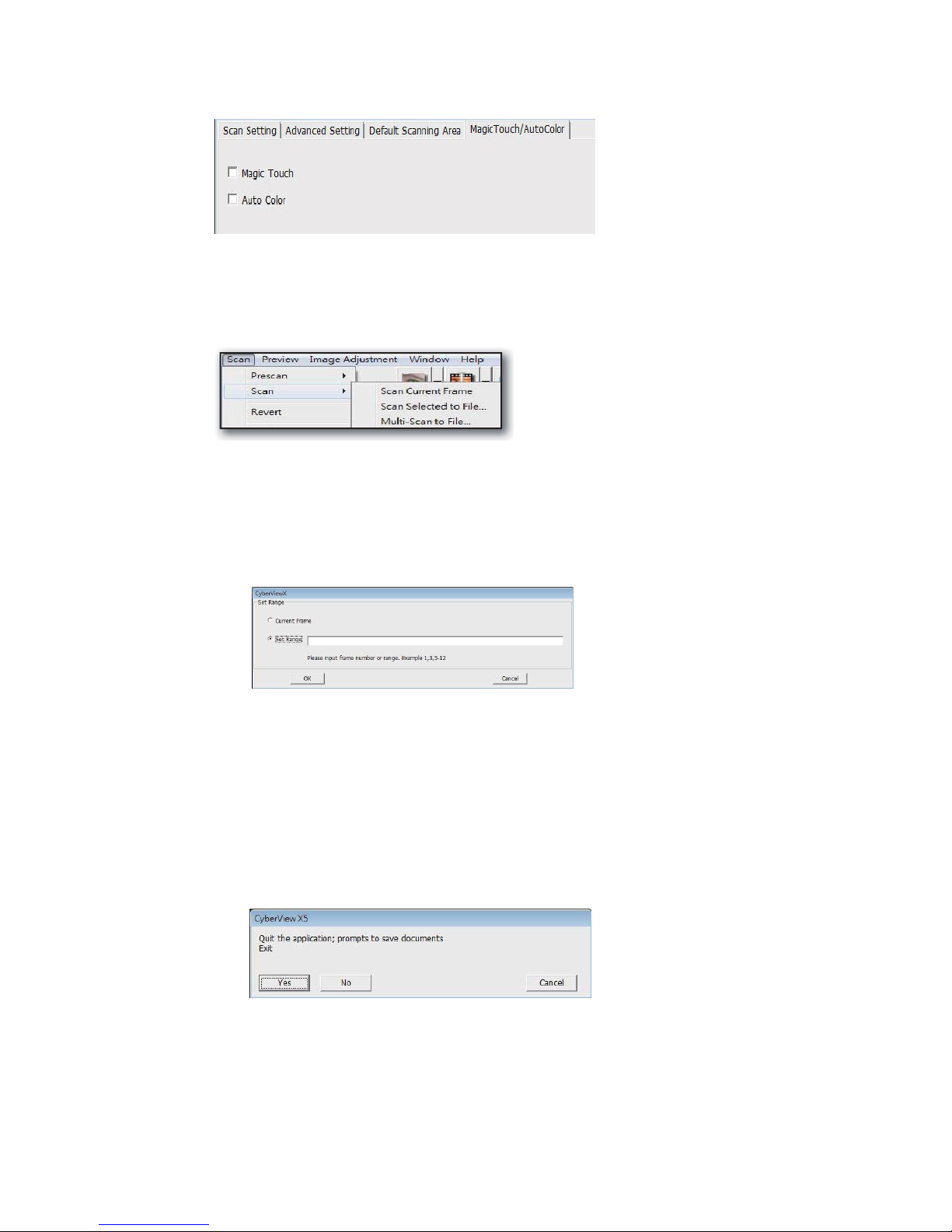
STEP 6 –
Scan
To Scan a Single slide - Choose “Scan Current Frame” to scan the slide
loaded
slides to be
into the scanner or “Multi-Scan…” to input the number of
scanned
based on their location in the
magazine.
1. Scan Current Frame > Scan the current
2. Scan Selected to File > Scan the selected slide(s) to a specified
(Pre-scanning required)
3. Multi-Scan to File… > Scan slide(s) numbers and/or
slide.
path
.
range. Set this for 1
-50 slides, if
you have less slides in the tray, count how many then enter 1-? and the number of slides
currently in the tray, Example 10, then enter 1-10
STEP 7 –
Exit
All scanned images will be saved to the directory location set
previously,
the factory default locations
are:
Windows:
MAC: Mac
C:\Users\[YOUR NAME\Documents;
HD\Users\[YOUR NAME]
Select “Scan > Exit” to close the software. Scanned image files can be
open/edited
with any image editing
software.
14
Page 19
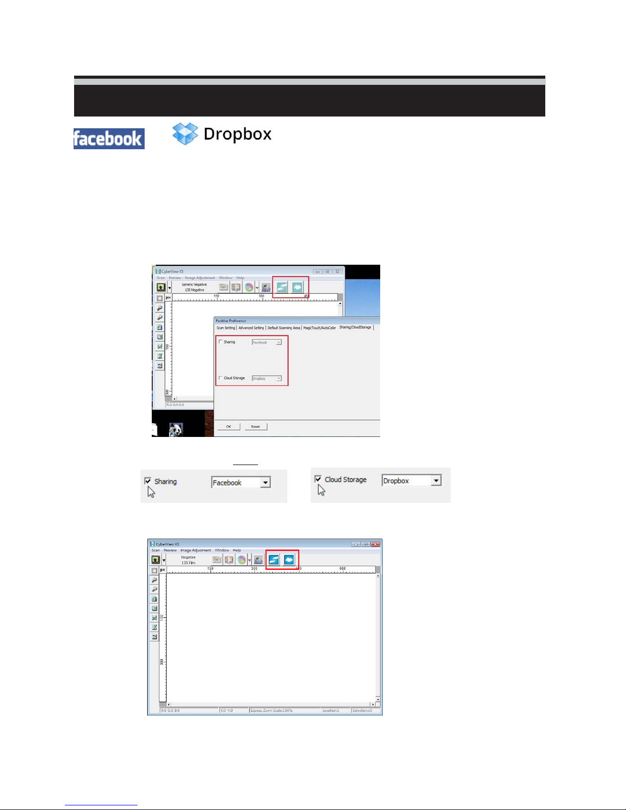
Sharing/CloudStorage
/
Simply designed and easy to use
Open the CyberviewX 5 software, you will need to select positive for slides or negative for film
strips.
Configure the Scan setting - Scan – Preference - Film Type – Sharing/Cloud Storage
Note: The tool bar options are disabled until activating (adding a check mark to the selected option) in
the Settings window
Select your method either Sharing or Cloud
Then Click “OK” The toolbar icons are now active
15
Page 20
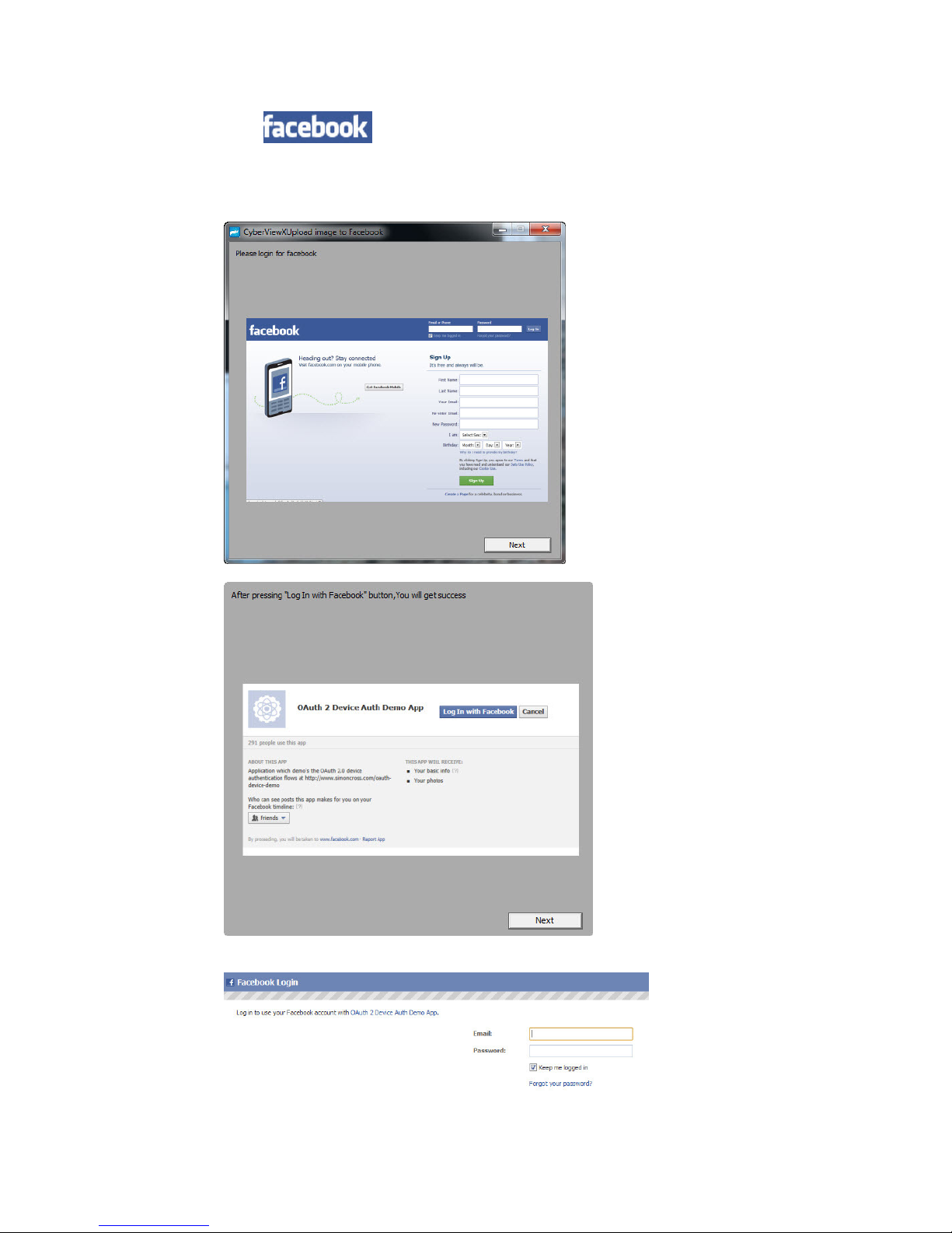
Scanning into , you must first log out of your account, the scanning function
will require authentication/login on each use
1. Log off of your Facebook account
2. In the Cyberview interface activate Sharing feature as described above
3. Follow the onscreen prompts to log in and authenticate the device
16
Page 21
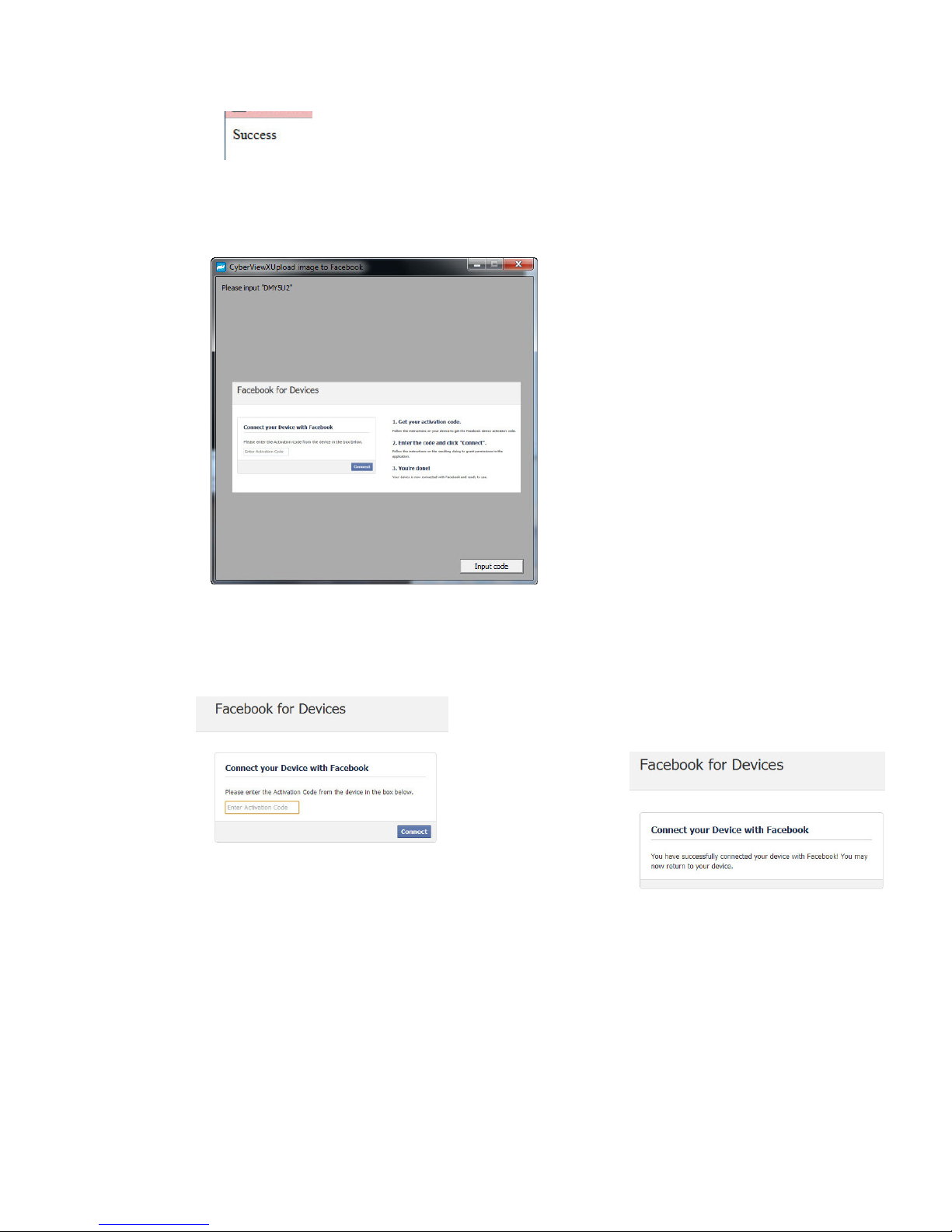
Minimize this browser window
4. Minimize the browser window and on the next CyberView screen, not
the Code number you have been given (this will be a different code every time, make a
note of it, you will need to enter it on the Facebook website.
5. Enter the code you made a note of earlier, then click Connect
6. Your scanner is now connected
to Facebook
17
Page 22
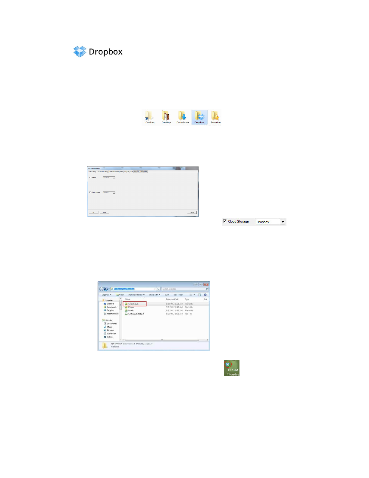
To scan to , you must first go here: https://www.dropbox.com/
and sign up for an account and download and install their software, if you are not currently a Dropbox
member and would like to use this service.
Once you have created and installed Dropbox application you will now have a new folder
on your computer that you may select to scan into for automatic sync uploads with your
Dropbox account.
To scan into the Dropbox folder
1. Open Cyberview X5
2. Next select Scan – Preference – the film type you wish to scan (Positive or Negative)
3. In this scan settings window select the Sharing and CloudStorage tab
4. Check the box beside CloudStorage to activate it
NOTE: When selecting the CloudStorage - Dropbox feature the software will automatically
scan to the CyberviewX folder it creates in your Dropbox folder on your computer, ready
for
synchronization with your Dropbox account.
5. Click OK to save settings, Once configured you are ready to scan.
6. All the files scanned will be saved into the Dropbox folder
Synchronization will automatically occur with your online account when active.
(Active=Dropbox is running in the system tray)
18
Page 23
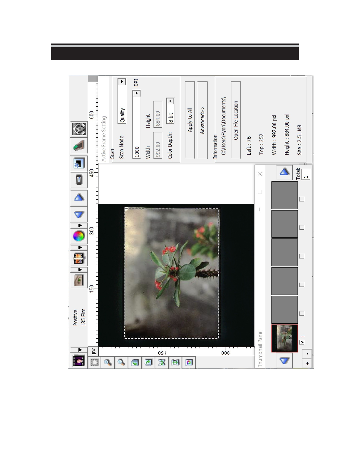
USER INTERFACE
I. Main Window Area
19
Page 24
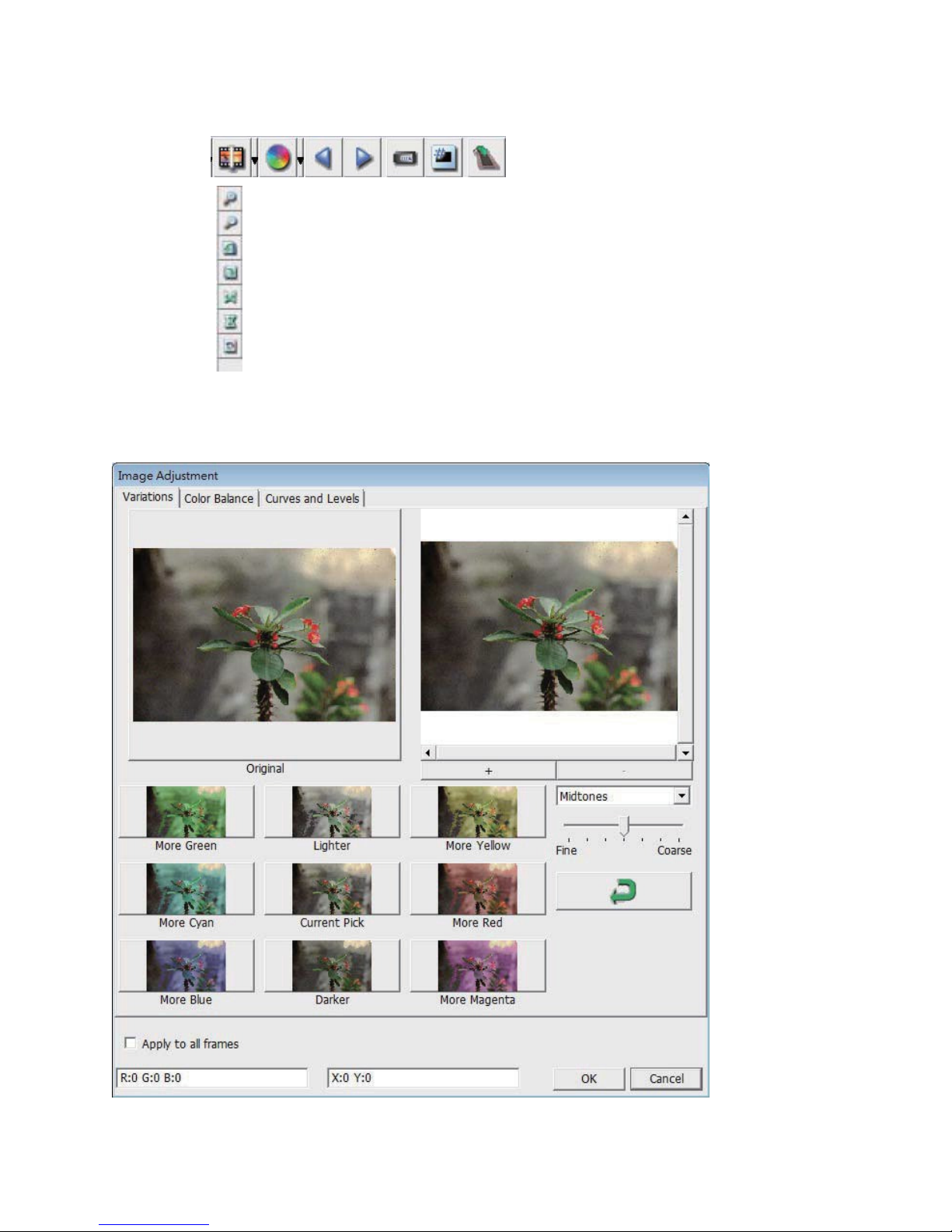
Menu Commands -
Preview
1. Zoom In: Magnify
2. Zoom Out: Reduce
image.
image.
3. Rotate 90 Left: Turn the image 90° counter
4. Rotate 90 Right: Turn the image 90°
5. Flip Horizontal: Flip the image
6. Flip Vertical: Flip the image
7. Revert: Discard all modifications and restores the image back
to
the
original state in preview
horizontally.
vertically.
windows.
a. Image
Adjustment
1. Variations: Generates different views of image with options to
changes to highlights, mid-tones,
etc.
clockwise.
clockwise.
make
22
Page 25
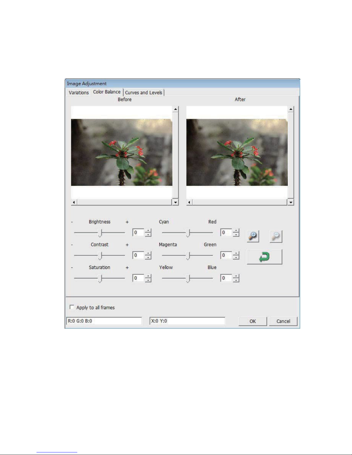
2. Color
Balance
To adjust the brightness, contrast, saturation, and color (CMY or
Comparisons between before and after adjusted
images
RGB) of
are shown for
the image.
reference.
Example: If a previewed image appears too dark, use the
“Brightness”
image by selecting the slider in the center
right. The image’s “After” view becomes lighter. Select “OK” to
accept
This can also be used
Balance” by contrast, saturation and
magenta and
23
slider in
the
“Color Balance” window to adjust the
and
moving it to the
the changes which will be sent to the scanning hardware.
to
adjust each of the functions in “Color
yellow.
specific
color ranges of cyan,
Page 26
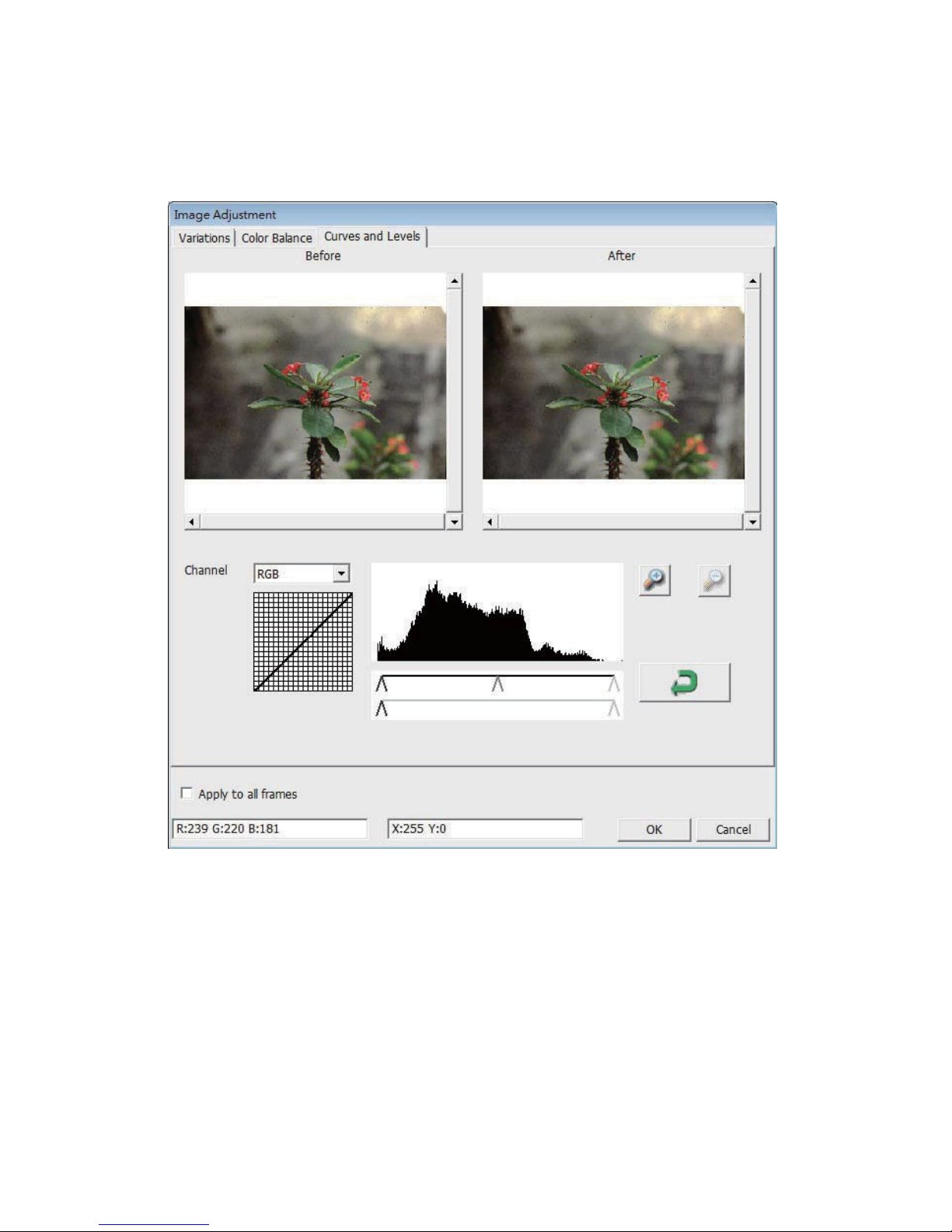
3. Curves and
Adjust image settings by moving Curve and Levels
between before and after adjustment is displayed
Levels
settings.
for reference.
Comparison
Example: When the previewed image appears to be too dark,
adjustments with
window can be made to correct the
slider in the center and moving it to the left will result
in the “After” view resulting in a lighter image. Once the adjusted
image is
acceptable select “OK” to send changes to the scanning
hardware. The
color channel
menu “RGB = All colors” R = Red, G = Green, and B =
the Input slider in the Curves and Levels
im-
age. Selecting the Gray
same
method can also be used to adjust each
independently,
using
the
channel drop down
in
Blue.
changes
24
Page 27
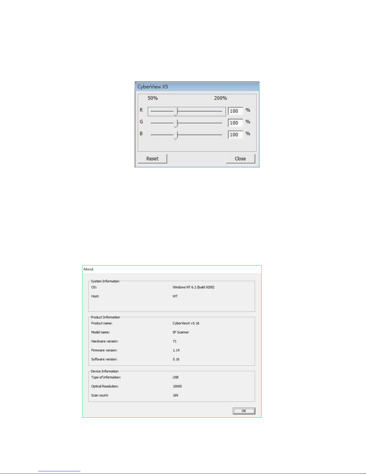
Menu Commands -
Windows
1. Exposure Setting: To adjust the exposure time (R, G, B) press ”Reset” to restore
the default
setting.
to
Menu Commands -
Help
Update: Firmware: Upgrade the firmware version, select the path where the
file
of
firmware has been saved. (These files may be
website)
downloaded
from our
About: Displays system information (including operation system, CPU),
information (including product name, model name, hardware version, firmware
software version, device information including interface and
optical resolution).
product
ver
sion,
25
Page 28
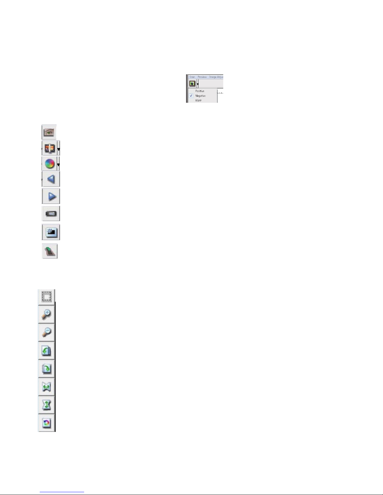
Function Bar
Diagram
In order to optimize scanned image quality, please select your
film
type
and brand from the
toolbar:
Negative Positive
(also known
as Slide) Black
and White
Prescan: Pre-scan the current film, press drop down for more
options.
Scan: Scan film, press drop down button for more options.
Image
Adjustment: Press drop down button for more
options.
Backward One Frame: Moves film back one frame.
Forward
One
Frame: Moves film forward one frame.
Reload Magazine: Reset
the
frame number, the location number will
Set Current Position: Change the current slide position number in
returned to
be
the magazine.
1
Go to: A pop-up dialogue box will prompt to enter which frame to change
to.
II. Preview Window Area [Fixed
Toolbar
Diagram
Windows]
Select scan area: more than one selection can be made at a
Zoom In: To magnify the image where the cursor is currently located. The
with every click until the maximum multiple (1000%)
Zoom Out: To reduce the size of the viewed image click the Zoom Out cursor
image will reduce by half with every click until the
Rotate 90 Left: To rotate the image counter clockwise 90
Rotate 90 Right: To rotate the image clockwise 90 degrees.
Flip
Horizontal: To Flip the image 180 degrees
Flip Vertical: To Flip the image 180 degrees
Revert: Discard all
preview
windows.
modifications
and restores the image back to the original
lowest
horizontally.
vertically.
time.
is reached.
multiple (25%) is r
degrees.
image
will be magnified
to
the desired area, the
eached.
state
in
26
Page 29
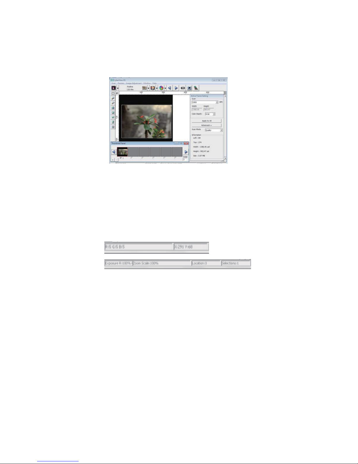
Preview
Window
Preview the image you pre-scan, you can select the measurement unit
by clicking the upper-left
corner.
“in“-“cm“-
“px“
Status
Line
In the lower left hand corner, the color level (RGB: red, green, blue) Displays
the
RGB (Red, Green, Blue) values in the image at the current pointer location
[ex:
I].
The zoom scale, the current slide magazine location and how many
selected
to scan (2 or higher indicates: Multiple scan areas on one slide [ex:
areas
II].
I.
II.
27
Page 30
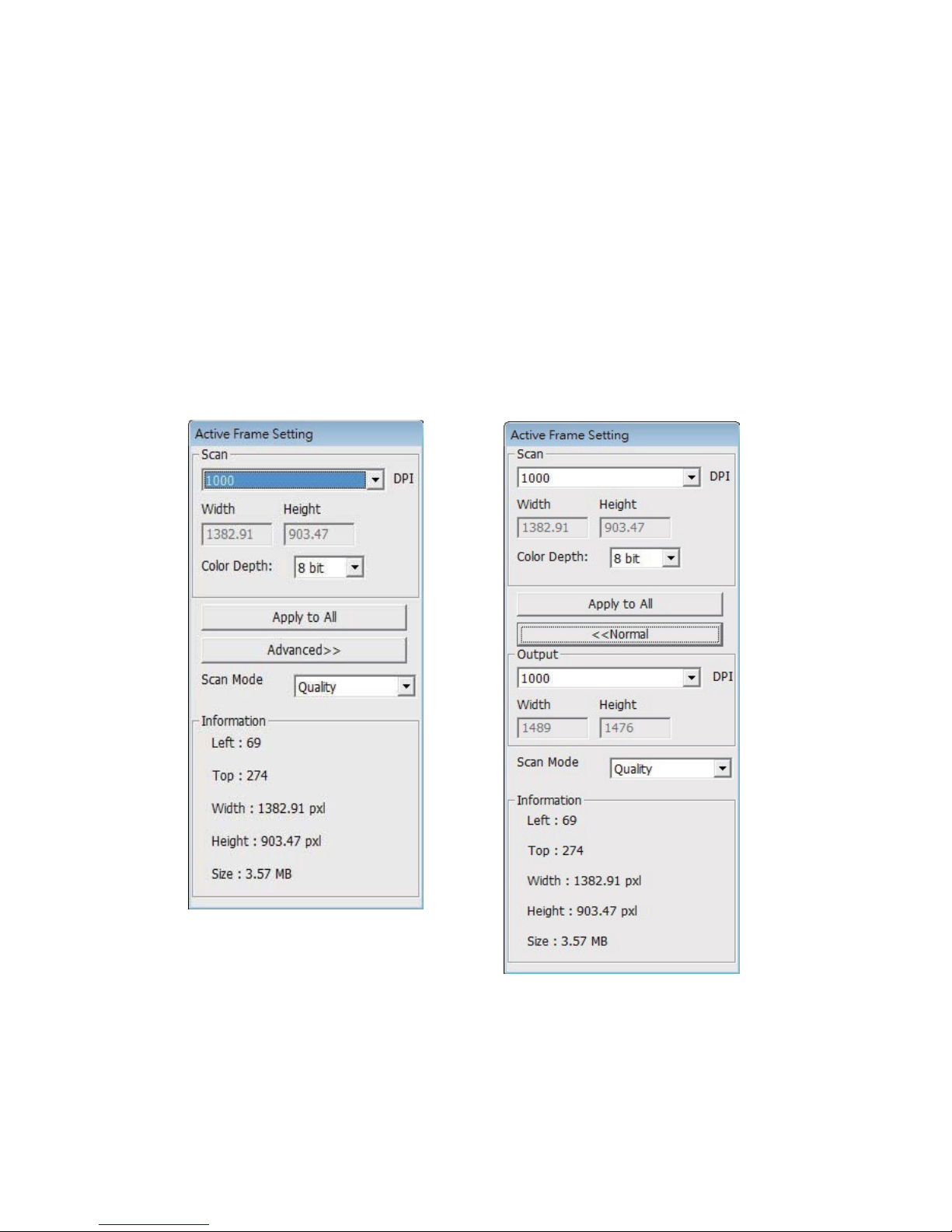
III. Active Frame Setting Area [Floating
Windows]
A
comprehensive
defined adjustments.
advanced mode is available to allow for more user
Normal mode [ex: I] to input the basic parameter to scan
(including
scan
resolution, film size, color
depth).
Advanced mode [ex: II]to input the parameter of scan and output
(including
size, scan
scan resolution, size, color depth and output resolution,
mode).
The “Active Frame Setting” only imitates in the current preview image,
click
“Apply to All” to set parameters in all previewed images, does not
apply to
direct
scanning to
file.
248
Page 31
29
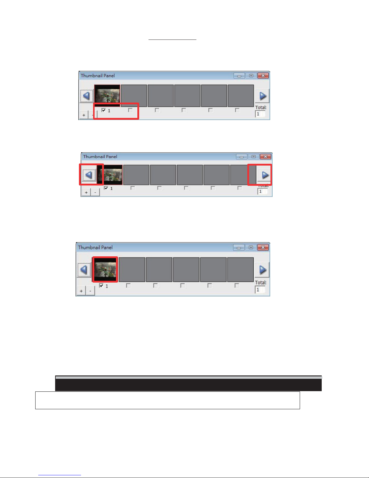
IV. Thumbnail Panel Area [Floating
Images only appear here in Prescan mode ONLY, scan to file goes directly
drive, this window remains blank as does the main
Displays thumbnail view of pre-scanned images. By default all
selected. Note the small check mark below each
When scanning more than 6 frames (6 at a time are viewable in the
scroll to view more by clicking on the right arrow button. The
you to scroll through pre-scanned images with
To de-select frames you do not wish to scan click on the check mark
remove
selection.
Windows]
to
the hard
Cyberview window.
image.
ease.
pre-scanned
left
images are
thumbnail
/ right arrow buttons allow
box
to
panel) you may
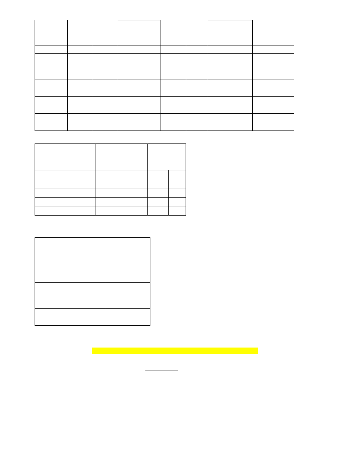
SCAN DPI SETTINGS ADDITIONAL INFORMATION
Image sizes based on 36 x 24 mm area
(your file sizes will differ based on cropping area)
Page 32
Scan
File Size
File Size
TIFF
Resolution
300 dpi 8-bit 24-bit 0.362 MB 16-bit 48-bit 0.723 MB 415 x 267
500 dpi 8-bit 24-bit 1.004 MB 16-bit 48-bit 2.009 MB 692 x 446
600 dpi 8-bit 24-bit 1.446 MB 16-bit 48-bit 2.893 MB 830 x 535
1000 dpi 8-bit 24-bit 4.018 MB 16-bit 48-bit 8.035 MB 1384 x 892
1800 dpi 8-bit 24-bit 12.965 MB 16-bit 48-bit 25.930 MB 2492 x 1607
2500 dpi 8-bit 24-bit 25.110 MB 16-bit 48-bit 50.220 MB 3461 x 2232
3600 dpi 8-bit 24-bit 52.068 MB 16-bit 48-bit 104.136 MB 4954 x 3214
5000 dpi 8-bit 24-bit 100.440 MB 16-bit 48-bit 200.880 MB 6922 x 4464
7200 dpi 8-bit 24-bit 208.273 MB 16-bit 48-bit 416.546 MB 9968 x 6429
10,000 dpi 8-bit 24-bit 401.761 MB 16-bit 48-bit 803.522 MB 13,845 x 8929
Color
Depth
Color
Mode
TIFF
(no compression)
Color
Depth
Color
Mode
(no compression)
Pixel
Dimensions
Print dpi output sizes if scanning resolution is 7200 dpi
Standard
Photograph Sizes
scan/crop ratio
of print output
4x6 6.0 x 4.014 1668 dpi
5x7 7 x 4.683 1430 dpi
8x10 10 x 6.691 1001 dpi
11x14 14 x 9.367 715 dpi
16x20 20 x 13.381 500 dpi
To Generate 300 dpi prints
Resolution for 300 dpi Prints
Actual print ratio from
35mm slide
6.0 x 4.014 1295 dpi
7 x 4.683 1511 dpi
10 x 6.691 2158 dpi
14 x 9.367 3022 dpi
20 x 13.381 4317 dpi
36 x 24.09 7770 dpi
Actual
Minimum Scan
dpi needed
Print
Resolution
would be
Screen images differ slightly but commands identical for PC and MAC
Basic Quick Scanning or once you have everything configured to your liking
1. Turn on scanner wait for green light to come on solid, indicating it is fully warmed up
2. Open Cyberview and click on Reload Magazine icon on the toolbar, to rest the scanners internal counter back to
ZERO, this will alleviate it stopping for no apparent reason mid tray
Tips for Hassle Free Scanning
30
Page 33
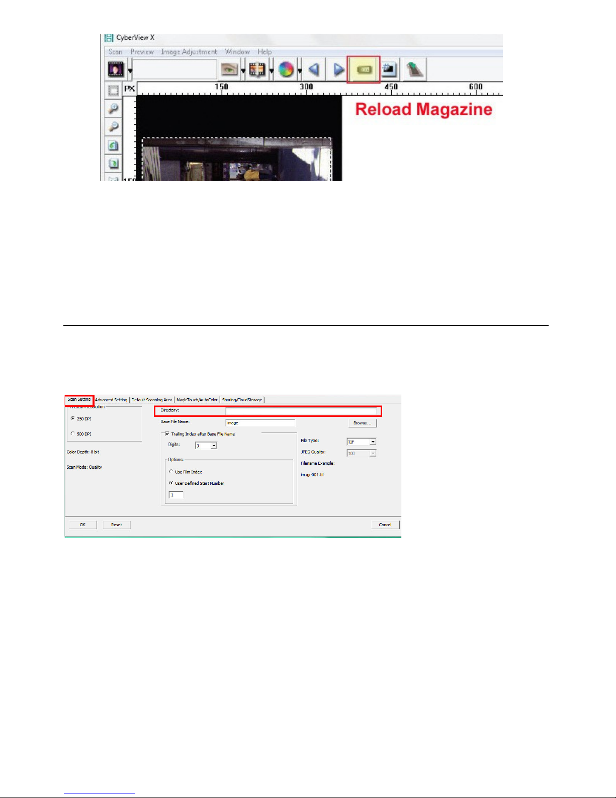
3. Load the tray full of slides, and then begin your scanning
4. Go to Scan – Scan – Multi-Scan to file – set Range 1-50 more detailed information below
NOTE:
If the scanner sits quietly for 10-15 minutes it will go to sleep and loose communication
EXAMPLE: You set it up to scan a tray, then walk away, it then finishes and has been sitting, the software will then
produce “Unable to communicate” errors
TO FIX: You must Close Cyberview, Turn off the scanner, wait 10 seconds, turn on the scanner and then wait for the full
warm up to a solid green light before starting the Cyberview software again.
Advanced Tips
Slide numbering tips
Go to Scan – Preference - Positive Film – This is where you will set up your desired configuration settings
Directory – This is where the files will be saved to
31
To change the Default Save to location select BROWSE
Page 34
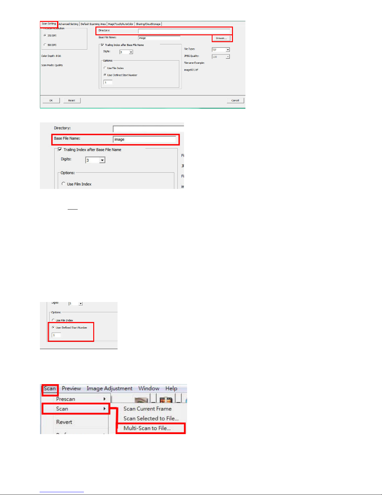
Base File Name is the name each file will be given with a number following
Trailing Index after base file name - Is the number of digits you would like in your file naming sequence, default number
is 3 - Image001, you can select 1-6 digits for this which would result in naming as follows Image1, Image01, Image001,
Image0001, Image0001, Image00001, Image000001 – this can be changed at any time
Example Image001 is the default so the files will be named Image001, Image002 and so on
You can customize this to a name of your choosing to aid in organization
Examples: Germany_ would result in file names Germany_001, Germany_002
Or
Slides_ then the names would be Slides_001, Slides_002 the underscore leaves a nice separation from the number of the
file, another option is to use years
1970_ file names would be 1970_001, 1970_002, 1970_003 etc.
User Define Start number – this allows custom numbering and when selecting SAVE on exit will keep track of where you
left off, on what slide number next in the sequence, Film index counts the slot #’s and can get tricky if you scan less than
full trays or have to start in the middle after a jam.
When batch scanning the included tray holds 50 slides, therefore when selecting Scan – Multi-Scan to File - Set Range it
will be the PHYSICAL number of slides in the tray 1-50 if full, or 1- however many you have in the tray
32
Page 35
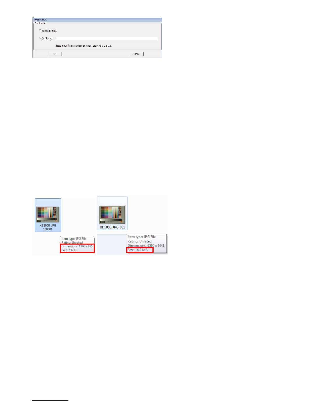
Current Frame applies to scanning a single slide inserted through the top slide holder
NOTE: This number will only EVER go over 50 if you are using the aftermarket BRAUN Carousel then it will be Range 1-100
as this carousel must always be used full to keep the weight evenly distributed.
File Type
TIF – Uncompressed best quality – Best used when you want to post edit the scans before burning to DVD etc. provides
the most data to work with when editing
JPG - Compressed – compression is advanced making the files small – compresses and discards much of the original
scanned image data during the save process
EXAMPLE an 1000 dpi, 8 bit (billions of colors) TIF image is approximately 3.83 MB, selecting the JPG 100 will give you a less
than 786 kb image from that original 3.83 MB and if you select 16 bit color (trillions of colors) the TIF would be 7.87 MB vs
the same 786 kb for JPG, because JPG compression does not support 16 bit color option.
For the best possible images for editing use TIF - 16 bit
For Archiving for just burning to disk making slide shows etc. no editing involved, JPG is a good choice
Also if you scan at 5000 dpi the TIF would be 196.7 MB and the resulting JPG will be of much higher quality at 16.2 MB
NOTE: The scanner can only physically scan TIF images, the JPG conversion is all handled by the software, so scanning in
TIF vs JPG using the same resolution settings will not result in longer scan times, only DPI settings can affect this.
33
Page 36
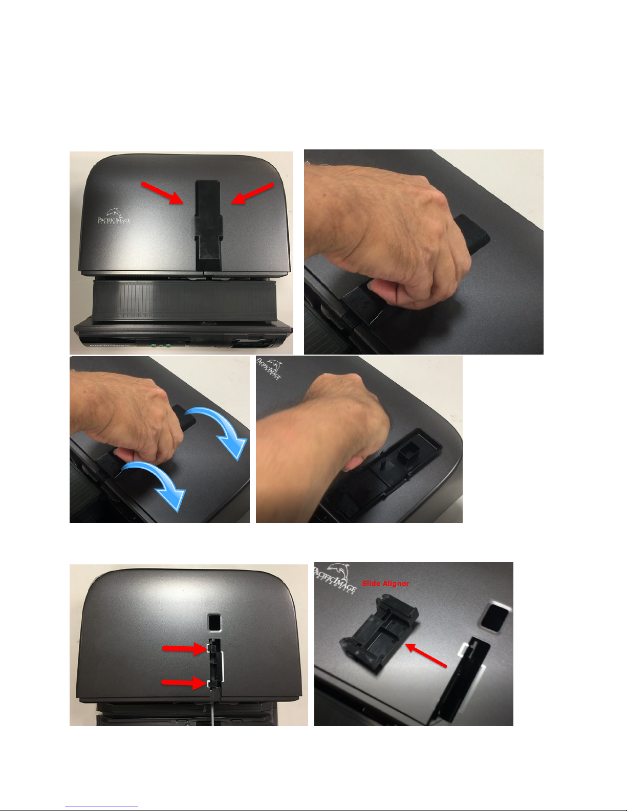
Removing a jammed slide from inside the scanner
1. Close the CyberView scanning software
2. Turn off the scanner power, disconnect the power cable from the back of the unit
3. Remove the cap from the slide retrieval area (Fig. 1)
4. Next remove the inner slide aligner (Fig 2.) by lifting straight up and out
5.
Fig. 1
Fig. 2 Lift up and out
34
Page 37
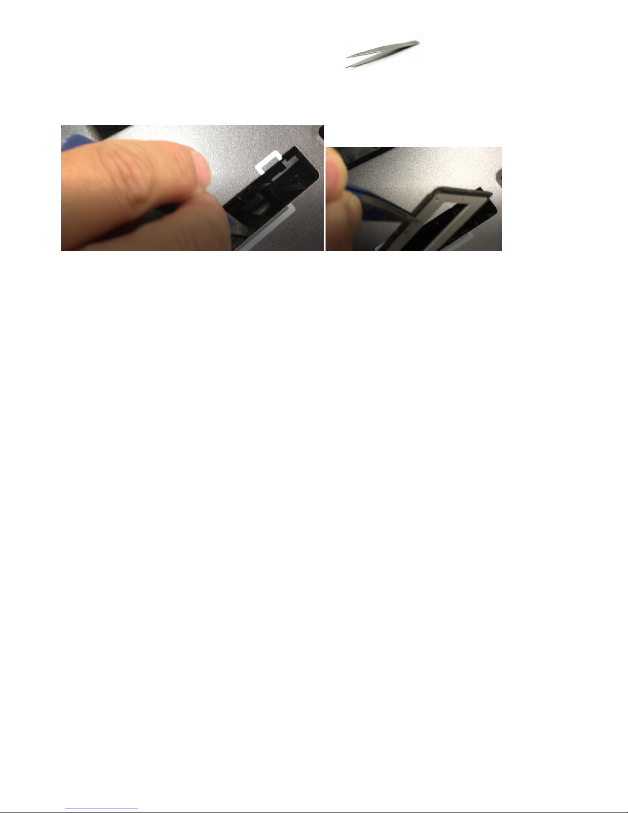
5. Now you have access to the inside, using thin tweezers
Reach inside and grab the stuck slide (Fig. 3)
Fig. 3
6. Once stuck slide has been retrieved, replace slide aligner, and cover back onto the scanner.
35
Page 38

TECHNICAL SUPPORT
CyberViewX
For information regarding the film scanner and CyberView driver, please visit
www.scanace.com
Transporting the device
For safety purposes, follow the procedure below before transporting the canner (i.e.
before moving the scanner from one location to another or packing and shipping the
unit):
1. Plug in the power adaptor. Turn on the power switch.
2. Wait for the scanner to warm up (around 3 minutes).
The LED indicator will always blink during warm up.
3. After LED indicator turns ON solid, turn off the power switch.
36
 Loading...