

Page 1

IEEE802.11g Wireless
LAN CardBus Card
WE602-P
User’s Manual
Rev 0.1
Page 2

54M Wireless LAN CardBus Card User’s Manual
Federal Communication Commission Interference Statement
This equipment has been tested and found to comply with the limits for a Class B
digital device, pursuant to Part 15 of the FCC Rules. These limits are designed to
provide reasonable protection against harmful interference in a residential installation.
This equipment generates, uses and can radiate radio frequency energy and, if not
installed and used in accordance with the instructions, may cause harmful interference
to radio communications. However, there is no guarantee that interference will not
occur in a particular installation. If this equipment does cause harmful interference to
radio or television reception, which can be determined by turning the equipment off and
on, the user is encouraged to try to correct the interference by one of the following
measures:
- Reorient or relocate the receiving antenna.
- Increase the separation between the equipment and receiver.
- Connect the equipment into an outlet on a circuit different from that
to which the receiver is connected.
- Consult the dealer or an experienced radio/TV technician for help.
FCC Caution: Any changes or modifications not expressly approved by the party
responsible for compliance could void the user's authority to operate this equipment.
This device complies with Part 15 of the FCC Rules. Operation is subject to the
following two conditions: (1) This device may not cause harmful interference, and (2)
this device must accept any interference received, including interference that may cause
undesired operation.
IMPORTANT NOTE:
FCC Radiation Exposure Statement:
This equipment complies with FCC radiation exposure limits set forth for an
uncontrolled environment.
This transmitter must not be co-located or operating in conjunction with any other
antenna or transmitter.
This device is intended only for OEM integrators under the following conditions:
1) The transmitter module may not be co-located with any other transmitter or antenna.
As long as conduction above is met, further transmitter test will not be required.
However, the OEM integrator is still responsible for testing their end-product for any
additional compliance requirements required with this module installed (for example,
digital device emissions, PC peripheral requirements, etc.).
IMPORTANT NOTE: In the event that these conditions can not be met (for example
certain laptop configurations or co-location with another transmitter), then the FCC
authorization is no longer considered valid and the FCC ID can not be used on the final
product. In these circumstances, the OEM integrator will be responsible for reevaluating the end product (including the transmitter) and obtaining a separate FCC
authorization.
End Product Labeling
The final end product must be labeled in a visible area with the following: “Contains
TX FCC ID: N89-WE602P''
2
Page 3

54M Wireless LAN CardBus Card User’s Manual
Manual Information That Must be Included
The OEM integrator has to be aware not to provide information to the end user
regarding how to install or remove this RF module in the users manual of the end
product which integrate this module.
The users manual for OEM integrators must include the following information in a
prominent location “ IMPORTANT NOTE: To comply with FCC RF exposure
compliance requirements. The antenna must not be co-located or operating in
conjunction with any other antenna or transmitter.
IMPORTANT NOTE:
FCC Radiation Exposure Statement:
This equipment complies with FCC radiation exposure limits set forth for an uncontrolled
environment.
This transmitter must not be co-located or operating in conjunction with any other
antenna or transmitter.
CyberTAN declared that WE602-P is limited in CH1-CH11 by specified
firmware controlled in USA
About this manual
This User’s Manual describes how to install and operate your CardBus Wireless
LAN Card. Please read this manual before you install the product.
This manual includes the following topics:
Ø Product description and features.
Ø Hardware installation procedure.
Ø Software installation procedure.
Ø FAQ
3
Page 4

54M Wireless LAN CardBus Card User’s Manual
Table of Contents
About this manual 3 / Federal Communication
Commission Interference Statement 3
Chapter 1 - Introduction.................................................5
Features..................................................................................................5
What is Wireless LAN?...........................................................................6
Wireless LAN Modes..............................................................................6
Notes on Wireless LAN Configuration...................................................7
Chapter 2 - Hardware Installation ...................................8
Package Contents...................................................................................8
System Requirements for the Adapter...................................................8
Hardware description..............................................................................8
Inserting the Wireless LAN Card............................................................8
LED Indicators.........................................................................................9
Ejecting the Wireless LAN card..............................................................9
Chapter 3 – Driver Installation for Windows..................11
Driver installation for Windows 98........................................................11
Driver installation for Windows 2000..................................................14
Driver installation for Windows ME.....................................................17
Driver installation for Windows XP...................................................... 19
Chapter 4 – Installing and Using the Wireless Utility..... 21
Installation in Windows........................................................................21
Using Wireless Utility In Windows XP.................................................24
Use Windows Wireless Network Configuration..................... 24
Use Wireless LAN Utility.........................................................27
Use Wireless LAN Utility In Windows 98, 2000 and ME.................... 30
Configuring the CardBus Wireless LAN Card ....................................30
Chapter 5 – Installing Network Protocols ......................35
Installing the Network Protocols for Windows 98 and Millennium.....35
Appendix A – FAQ....................................................... 38
Appendix B – Specifications ........................................ 39
4
Page 5

54M Wireless LAN CardBus Card User’s Manual
Chapter 1 - Introduction
Thank you for purchasing the CardBus Wireless LAN Card. This high-speed CardBus
Wireless LAN Card provides you with an innovative wireless networking solution. The
Adapter is easy to set up and use. With this innovative wireless technology, you can
share files and printers on the network—without inconvenient wires!
The Adapter is a network Adapter with a rate of 1, 2, 5.5, 6, 9, 11, 12, 24, 36, 48
and 54 Mbps operating in the ISM band using Direct Sequence Spread Spectrum
(DSSS) transmission implementing the IEEE 802.11g draft standard. This Adapter
provides Device Drivers for Windows Operating Systems. It also provides tools for
the configuration of the Adapter. The tool, as well as the installation steps of the
plug-and-play procedure for the Windows operating systems, is described in this
document.
Features
The CardBus Wireless LAN Card offers compliance with the IEEE 802.11g draft
specification. This feature allows them to communicate with other wireless devices
that support the standard. Features of the Adapter are:
l Uses 2.4GHz frequency band, which complies with worldwide
requirement
l Wireless interface following the IEEE 802.11g draft standard
l Using CardBus interface
l Enciphering/deciphering of wireless data by the implementation of the
WEP algorithm
l Wire-free access to networked resources from anywhere beyond the
notebook
l Allows users move between Access Points without resetting their
connection reconfiguration
l Delivers data rate up to 54 Mbps
l Supports 1, 2, 5.5, 6, 9, 11, 12, 24, 36, 48 and 54 Mbps rates
l Provide CardBus Wireless LAN Card Configuration utility
l The Adapter uses external Antenna with LEDs indicating Power and Link
l Supports most popular operating systems
5
Page 6

54M Wireless LAN CardBus Card User’s Manual
What is Wireless LAN?
Wireless Local Area Network (WLAN) systems offer a great nu mber of advantages
over traditional wired systems. WLAN is flexible and easy to setup and manage.
They are also more economical than wired LAN systems.
Using radio frequency (RF) technology, WLAN transmit and receive data through
the air. WLAN combine data connectivity with user mobility. For example, users
can roam from a confe rence room to their office without being disconnected from
the LAN.
Using WLAN, users can conveniently access-shared information, and network
administrators can configure and augment networks without installing or moving
network cables.
WLAN technology provides users with many convenient and cost saving features:
• Mobility: WLAN provide LAN users with access to real-time information
anywhere in their organization, providing service opportunities that are
impossible with wired ne tworks.
• Ease of Installation: Installing is easy for novice and expert users alike,
eliminating the need to install network cables in walls and ceilings.
• Scalability: WLAN can be configured in a variety of topologies to adapt to
specific applications and installations. Configurations are easily changed and
range from peer-to-peer networks suitable for a small number of users to full
infrastructure networks of thousands of users roaming over a broad area.
Wireless LAN Modes
Wireless LANs can be configured in one of two ways:
Ad-hoc
Networking
Also known as a peer-to-peer network, an ad-hoc
network is one that allows all workstations and
computers in the network to act as servers to all other
users on the network. Users on the network can share
files, print to a shared printer, and access the Internet
with a shared modem. However, with ad-hoc
networking, users can only communicate with other
wireless LAN computers that are in the wireless LAN
workgroup, and are within range.
Infrastructure
Networking
Infrastructure networking differs from ad-hoc networking
in that it includes an access point. Unlike the ad-hoc
structure where users on the LAN contend the shared
bandwidth, on an infrastructure network the access
point can manage the bandwidth to maximize
bandwidth utilization.
Additionally, the access point enables users on a
6
Page 7

54M Wireless LAN CardBus Card User’s Manual
wireless LAN to access an existing wired network,
allowing wireless users to take advantage of the wired
networks resources, such as Internet, email, file
transfer, and printer sharing.
Infrastructure networking has the following advantages
over ad-hoc networking:
• Extended range: each wireless LAN computer
within the range of the access point can
communicate with other wireless LAN computers
within range of the access point.
• Roaming: the access point enables a wireless LAN
computer to move through a building and still be
connected to the LAN.
• Wired to wireless LAN connectivity: the access
point bridges the gap between wireless LANs and
their wired counterparts.
Notes on W ireless LAN Configuration
When configuring a wireless LAN (WLAN), be sure to note the following points:
• Optimize the performance of the WLAN by ensuring that the distance
between access points is not too far. In most buildings, WLAN Adapters
operate within a range of 100 ~ 300 feet, depending on the thickness and
structure of the walls.
• Radio waves can pass through walls and glass but not metal. If there is
interference in transmitting through a wall, it may be that the wall has
reinforcing metal in its structure. Install another access point to circumvent
this problem.
• Floors usually have metal girders and metal reinforcing struts that interfere
with WLAN transmission.
This concludes the first chapter. The next chapter deals with the hardware
installation of the Adapter.
7
Page 8

54M Wireless LAN CardBus Card User’s Manual
POWER
LINK
Chapter 2 - Hardware Installation
This chapter covers connecting your CardBus Wireless LAN Card to CardBus slot
of notebook.
Package Contents
Please make sure that items below are included on package.
ü One CardBus Wireless LAN Card
ü One CD containing drivers and documentation
ü One Quick Installation Guide
System Requirements for the Adapter
Ø Operating System: Microsoft Windows 98/ME/2000/XP
Ø Notebook with CD-ROM drive
Ø One free CardBus slot
Ø Pentium-Class 90MHz or higher
Hardware description
The Wireless LAN Card is encased in a stainless compact frame and has a 68-pin
connector for attaching to the CardBus port of notebook.
Inserting the Wireless LAN Card
Note!
These instructions apply to most notebook computers. For detailed
information on inserting PC cards into your notebook, consult the
notebook manual.
8
Page 9

54M Wireless LAN CardBus Card User’s Manual
Follow the procedure below to install the Wireless LAN card.
1. With 68-pin connector of the card facing the CardBus slots on notebook,
slide the card all the way into an empty slot.
2. Connect to a network.
LED Indicators
The following table describes the meaning of LED indicators:
LED MEANING
POWER
Indicates that the Adapter is powered on (solid green).
Indicates link status. It is normally blinking. When blin king,
LINK
indicates that the card is scanning the channels, and the link
is not active. When lit, indicates that the card is locked to a
channel, and the link is active.
Ejecting the Wireless LAN card
After disconnecting from the LAN, you can eject the Wireless LAN card from the PC
9
Page 10

54M Wireless LAN CardBus Card User’s Manual
Card slot of notebook.
Note!
Most notebooks have an eject lever or button for ejecting PC cards from the PC slots.
Consult your notebook manual for details.
Warning!
After hardware installation is completed, please go to Chapter 3 to install driver on
different Operating System.
In Windows XP/2000/ME/98 operating systems, you do not have to power
down the notebook to remove the card. The card is hot-swappable — you
can remove the card when the notebook is powered on. However,
Microsoft recommends that you stop the card. Refer to your Windows
2000/ME/98 online help for information on stopping the Wireless LAN
card.
To prevent data loss, do not eject the Wireless LAN card
when a data transmission is taking place. Exit your
communications program normally, stop the card if
necessary, and then r emove the card.
10
Page 11

54M Wireless LAN CardBus Card User’s Manual
Chapter 3 – Driver Installation for Windows
The following sections cover CardBus Wireless LAN Card driver installation in the
Windows Operating Systems.
Note!
You have to install your hardware first before you begin to install the
drivers.
Driver installation for Windows 98
Follow the steps below to install the CardBus Wireless LAN Card drivers for Windows
98.
1. Insert the CardBus Wireless LAN Card to CardBus slot of notebook first. (Refer to
Chapter 2 – Hardware installation.)
2. After Windows 98 detects the CardBus Wireless LAN Card, the Add New Hardware
Wizard window appears. Clicks Next to continue the installation.
3. A screen appears prompting you to select an installation method. Select Search for
the best driver for your device. (Recommended) and click Next to continue.
11
Page 12

54M Wireless LAN CardBus Card User’s Manual
4. Ensure that the CD-ROM drive is selected. Inserts the driver CD-ROM into your
CD-ROM drive and clicks Next to continue.
5. The following screen appears showing the driver search result. Click Next to
continue the installation.
12
Page 13

54M Wireless LAN CardBus Card User’s Manual
6. Windows 98 copies files to your hard disk. The following screen will appear to
inform you when the software installation has finished. Click Finish to finish the
installation.
7. The following screen will ask you to restart your computer to finish the installation.
Click Yes to reboot the system. After system reboot, the Wireless LAN Utility will be
installed automatically. Please go to Chapter 4 to install the utility.
13
Page 14

54M Wireless LAN CardBus Card User’s Manual
Note!
In most cases, Windows will automatically copy all of the files needed
for networking. If Windows asks you for the files and prompts you to
input the path to the files. Follow the instructions on your screen, and
then click OK to continue.
Driver installation for Windows 2000
Follow the steps below to install the CardBus Wireless LAN Card drivers for Windows
2000.
1. Insert the CardBus Wireless LAN Card to CardBus slot of notebook first. (Refer to
Chapter 2 – Hardware installation.)
2. After Windows 2000 detects the CardBus Wireless LAN Card, the Found New
Hardware Wizard window appears. Click Next to start the installation.
3. A screen appears prompting you to select an installation method. Select Search for
a suitable driver for my device (recommended) and click Next to continue.
14
Page 15

54M Wireless LAN CardBus Card User’s Manual
4. Ensure that the CD-ROM driver is selected and insert the driver CD-ROM into your
CD-ROM drive and click Next to continue.
5. The following screen appears showing the driver search result. Click Next to
continue the installation.
15
Page 16

54M Wireless LAN CardBus Card User’s Manual
6. The following screen appears. Click Yes to continue
7. The Windows has finished installing software for the device. Click Finish to finish
the installation.
16
Page 17

54M Wireless LAN CardBus Card User’s Manual
Then system will start to install Wireless LAN Utility. Please refer to procedures at
Chapter 4.
Driver installation for Windows ME
Follow the steps below to install the CardBus Wireless LAN Card drivers for Windows
ME.
1. Insert the CardBus Wireless LAN Card to CardBus slot of notebook first. (Refer to
Chapter 2 – Hardware installation.)
2. After Windows ME detects the CardBus Wireless LAN Card, the Add New
Hardware Wizard window appears. Select Automatic search for a better driver
(Recommended) and insert the driver CD-ROM into CD-ROM drive and click Next
to continue.
17
Page 18

54M Wireless LAN CardBus Card User’s Manual
3. The system will find the setup files and follow the instruction to copy files to your
hard disk. The following screen will appear when the software installation has
finished. Click Finish to finish the installation.
4. The following screen will ask you to restart your computer to finish the hardware
setting up. Click Yes to reboot the system. After system reboot, the Wireless LAN
Utility will be installed automatically. Please go to Chapter 4 to install the utility.
18
Page 19

54M Wireless LAN CardBus Card User’s Manual
Note!
In most cases, Windows will automatically copy all of the files needed
for networking. If Windows asks you for the files and prompts you to
input the path to the files. Follow the instructions on your screen, and
then click OK to continue.
Driver installation for Windows XP
Follow the steps below to install the CardBus Wireless LAN Card drivers for Windows
XP.
1. Insert the CardBus Wireless LAN Card to CardBus slot of notebook first. (Refer to
Chapter 2 – Hardware installation.)
2. After Windows XP detects the CardBus Wireless LAN Card, the Found New
Hardware Wizard window appears. Select Install the software automatically
[Recommended] and insert the driver CD-ROM into CD-ROM drive and click Next
to continue.
3. Click Continue Anyway to continue the installation.
19
Page 20

54M Wireless LAN CardBus Card User’s Manual
4. The Windows has finished installing software for the device. Click Finish to finish
the installation
Then system will start to install Wireless utility automatically. Please refer to
procedures at Chapter 4.
20
Page 21

54M Wireless LAN CardBus Card User’s Manual
Chapter 4 – Installing and Using the
Wireless Utility
The following sections cover the CardBus Wireless LAN Card utility installation and
configuration.
Installation in Windows
After you have installed driver, system will start to install Wireless LAN Utility. Please
follow the steps below to install the utility.
1. Once you see the following screen, click Next to continue.
2. The screen will show you the default destination chosen by the utility. Click Next to
continue or click the Browse button to select an alternate destination.
21
Page 22

54M Wireless LAN CardBus Card User’s Manual
3. The following screen will add program icons to the Program Folder . You may type a
new folder name or select one from the existing folders list. Click Next to continue
or click Back to review or change any settings.
4. The following screen shows the current settings, click Next to continue or click
Back to change the Destination Folder in step 3.
22
Page 23

54M Wireless LAN CardBus Card User’s Manual
5. The Windows has finished installing Wireless LAN Utility. The following screen will
ask you to restart your computer to finish the installation. Click Finish to reboot the
system.
After you have installed the utility, you will see the Wireless LAN Utility icon in the
Windows taskbar:
23
Page 24

54M Wireless LAN CardBus Card User’s Manual
Using Wireless Utility In Windows XP
Wireless LAN Utility
There are two ways to configure CardBus Wireless LAN Card. One is Wireless LAN
Utility; the other one is Windows Wireless Network Configuration.
Use Windows Wireless Network Configuration
1. Click the right key of the mouse and Exit Wireless LAN Utility.
2. Click Windows Wireless Network Configuration icon.
Windows Wireless Network Configuration
3. Click Advanced… button.
24
Page 25

54M Wireless LAN CardBus Card User’s Manual
4. Make sure “Use Windows to configure my wireless network settings” is checked
and click OK.
5. Click the Windows Wireless Network Configuration icon again to open the Windows
Wireless Network Configuration.
Windows Wireless Network Configuration
6. Select an available network and click Connect button.
25
Page 26

54M Wireless LAN CardBus Card User’s Manual
6. The Windows Wireless Network Configuration will be enabled. Click the Windows
Wireless Configure icon.
Windows Wireless Network Configuration is enabled
8. Click Properties to start Windows Wireless Network Configuration.
26
Page 27

54M Wireless LAN CardBus Card User’s Manual
Use Wireless LAN Utility
1. Exit the Wireless LAN Utility.
2. Click Windows Wireless Network Configuration icon.
Windows Wireless Network Configuration
3. Click Advanced… button.
27
Page 28

54M Wireless LAN CardBus Card User’s Manual
4. Make sure “Use Windows to configure my wireless network settings” is unchecked
and click OK button.
5. Click Start -> All Programs -> IEEE802.11g WLAN CardBus Card then click
IEEE802.11g WLAN CardBus Card Utility to restart IEEE802.11g WLAN Card.
28
Page 29

54M Wireless LAN CardBus Card User’s Manual
6. The Wireless LAN Utility will appear, Double-click the icon to open the configuration
utility.
Wireless LAN Utility
7. Click Re-Scan button to start Wireless LAN Utility. (Refer to Configuring the
CardBus Wireless LAN Card.)
29
Page 30

54M Wireless LAN CardBus Card User’s Manual
Use Wireless LAN Utility In Windows 98, 2000 and ME
Wireless LAN Utility icon
Icon Meaning
Green: indicates a connection is linked
to a wireless network.
Red: indicates that the wireless LAN
card is looking for an available access
point.
Double-click the icon to open the Wireless LAN Utility. (Refer to Configuring the
CardBus Wireless LAN Card.)
Configuring the CardBus Wireless LAN Card
1. This screen shows you the status of your current connection. Click Re-Scan to
search for wireless connection (the adapter will search for the connection
automatically when it is activated).
30
Page 31

54M Wireless LAN CardBus Card User’s Manual
2. Select the “Configuration” tab. The profile setting allows you to save
configurations in different profiles for different working environments. The default
profile will contain the initial configuration setting when you install the Card. Under
the Operating Mode drop-box, you may choose either Infrastructure or Ad-Hoc.
The Infrastructure mode allows a wireless adapter to communicate with a wired
network employing an Access Point, while the Ad-Hoc mode allows wireless-towireless, peer-to-peer communication. If you choose Infrastructure, the SSID
should have the same name as the Access Point. If you choose Ad-Hoc, all clients
should share the same SSID name. You can select Enabled Power Saving Mode
to allow your adapter to go to sleep mode while the adapter doesn’t precede the
data transmission. Or select Disabled to make the adapter never go to sleep mode.
Click Apply to save the settings.
31
Page 32

54M Wireless LAN CardBus Card User’s Manual
3. Select the “Site Survey” tab. The list on the adjacent screen shows you available
Access Points and their features. Click on the desired Access Point, and then click
Connect to connect or Search to search for more Access Points. Click OK when
you are finished.
32
Page 33

54M Wireless LAN CardBus Card User’s Manual
4. Click on the “Encryption” tab. Under the drop-box, you can choose to have WEP
encryption Disabled, 64-Bit, or 128-Bit. Wired Equivalent Privacy (WEP) is an
encryption scheme used to protect wireless data communication. The Disabled
setting prevents the sharing of data with other computers on the WEP network. For
data sharing to be enabled, select the level of encryption desired, either 64 or 128bit.
33
Page 34

54M Wireless LAN CardBus Card User’s Manual
5. The “About” tab shows you copyright and version information about the driver, the
configuration utility, and the firmware. Click OK to complete the configuration.
34
Page 35

54M Wireless LAN CardBus Card User’s Manual
Chapter 5 – Installing Network Protocols
Protocols are necessary for computers to be recognized on your network. Windows
2000 users need to check their Windows User Guides for protocol installation.
Installing the Network Protocols for Windows 98 and
Millennium
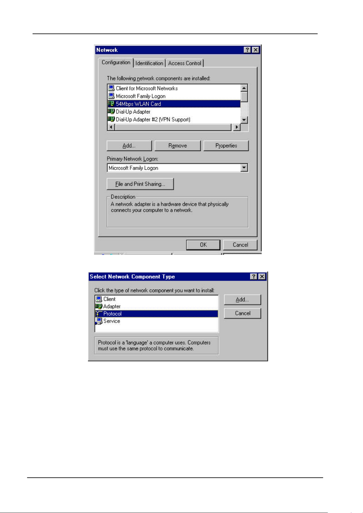
1. From the Start Menu, select Settings and bring up the Control Panel. From the
Control Panel, double-click on the Network icon.
Note!
2. Select 54Mbps WLAN Card from the list and click the Add button.
Before adding any network protocols, verify that the protocol is not
already installed. Never install duplicate protocols.
35
Page 36
54M Wireless LAN CardBus Card User’s Manual
3. Highlight Protocol and click the Add button.
4. Select Microsoft from the list of “Manufacturers” and TCP/IP from the list of
“Network” Protocols” and click the OK button to finish the installation.
36
Page 37

54M Wireless LAN CardBus Card User’s Manual
37
Page 38

54M Wireless LAN CardBus Card User’s Manual
Appendix A – FAQ
1. What is IEEE 802.11 standard?
Ø The IEEE 802.11 is a wireless LAN industry standard, and the objective
of IEEE 802.11 is to make sure that different manufactures’ wireless LAN
devices can communicate to each other.
2. What is WEP?
Ø As described in the IEEE 802.11 standard, WEP (Wired Equivalent
Privacy) is a data privacy mechanism based on a 40 bit shared key
algorithm.
3. Windows cannot recognize the CardBus Wireless LAN Card.
Ø Please make sure that the LAN Card is inserted into the CardBus slot of
your notebook properly (check this when the notebook is powered off).
Ø Please check if PC Card support is installed. Double-click the PC Card
icon on Control Panel. If PC Card support is not activated, you should
activate it now.
4. In Infrastructure mode, my notebook cannot communicate with the
others notebooks on the network.
Ø First, make sure that the SSID is same as the others notebook.
Ø Check if the WEP is enabled on the Access Point, if it is, set your
Adapter’s WEP the same as the Access Point .
Ø Also check the Access Point’s Authentication Type and Preamble Type
and match those settings.
5. In ad-hoc mode, my notebook cannot communicate with the others
notebooks on the network.
Ø Make sure the SSID and the Channel number are the same as other
wireless stations.
Ø Check if WEP settings are the same in all wireless stations.
Ø Check the Network Properties, make sure proper protocol is installed
and File and Printer Sharing is enabled.
38
Page 39

54M Wireless LAN CardBus Card User’s Manual
Appendix B – Specifications
Standards: IEEE 802.11g draft
Channels: 11 Channels (US, Canada)
13 Channels (Europe)
14 Channels (Japan)
Antenna: Built-in Chip Antenna
Frequency: 2.4 to 2.497GHz (Industrial Scientific Medical Band)
Transmit Power: 17dBm
Data Rate: up to 54Mbps
Operating Ranges: Ind oor (varies depends on the environment):
Up to 50M @ 11Mbps
Up to 30M @ 54Mbps
Outdoor (varies depends on the environment) :
Up to 150M @ 11Mbps
Up to 100M @ 54Mbps
Temperature: Operating: 0° ~ 50° C
Storage: -25° ~ 70° C
Humidity: 10% to 90% (non-condensing)
39
 Loading...