

Page 1
REVIEW DRAFT - CISCO CONFIDENTIAL - FOR COMPLIANCE PURPOSES ONLY
ADMINISTRATION
Cisco Small Business
RV 110W Wireless-N VPN Firewall
GUIDE
Page 2

CCDE, CCENT, CCSI, Cisco Eos, Cisco HealthPresence, Cisco IronPort, the Cisco logo, Cisco Nurse Connect, Cisco Pulse, Cisco SensorBase, Cisco StackPower,
Cisco StadiumVision, Cisco TelePresence, Cisco Unified Computing System, Cisco WebEx, DCE, Flip Channels, Flip for Good, Flip Mino, Flipshare (Design), Flip
Ultra, Flip Video, Flip Video (Design), Instant Broadband, and Welcome to the Human Network are trademarks; Changing the Way We Work, Live, Play, and Learn,
Cisco Capital, Cisco Capital (Design), Cisco:Financed (Stylized), Cisco Store, Flip Gift Card, and One Million Acts of Green are service marks; and Access
Registrar, Aironet, AllTouch, AsyncOS, Bringing the Meeting To You, Catalyst, CCDA, CCDP, CCIE, CCIP, CCNA, CCNP, CCSP, CCVP, Cisco, the Cisco Certified
Internetwork Expert logo, Cisco IOS, Cisco Lumin, Cisco Nexus, Cisco Press, Cisco Systems, Cisco Systems Capital, the Cisco Systems logo, Cisco Unity,
Collaboration Without Limitation, Continuum, EtherFast, EtherSwitch, Event Center, Explorer, Follow Me Browsing, GainMaker, iLYNX, IOS, iPhone, IronPort, the
IronPort logo, Laser Link, LightStream, Linksys, MeetingPlace, MeetingPlace Chime Sound, MGX, Networkers, Networking Academy, PCNow, PIX, PowerKEY,
PowerPanels, PowerTV, PowerTV (Design), PowerVu, Prisma, ProConnect, ROSA, SenderBase, SMARTnet, Spectrum Expert, StackWise, WebEx, and the WebEx
logo are registered trademarks of Cisco Systems, Inc. and/or its affiliates in the United States and certain other countries.
All other trademarks mentioned in this document or website are the property of their respective owners. The use of the word partner does not imply a
partnership relationship between Cisco and any other company. (0910R)
© 2010 Cisco Systems, Inc. All rights reserved. OL-21745-01
Page 3

Contents
Chapter 1: Introduction 1
Product Overview 1
Getting to Know the Cisco RV 110W 3
Front Panel 3
Back Panel 4
Mounting the Cisco RV 110W 5
Installation Guidelines 5
Wall Mounting 5
Connecting the Equipment 7
Using the Setup Wizard 8
Starting the Wizard 8
Connecting Your Hardware 9
Entering Login and Internet Connection Information 13
Configuring Security 14
Manually Connecting Your System 16
Verifying the Hardware Installation 17
Connecting to Your Wireless Network 17
Getting Started in the Cisco RV 110W Device Manager 18
Logging In 18
Using the Getting Started Page 19
Navigating through the Pages 20
Saving Your Changes 21
Viewing the Help Files 22
Viewing Device Statistics 22
Viewing the System Summary 22
Viewing the Wireless Status 25
Viewing the IPsec Connection Status 26
Viewing the QuickVPN Connection Status 27
Viewing Logs 27
Viewing Available LAN Hosts 28
Viewing the Port Triggering Status 28
Viewing Port Statistics 28
Cisco RV 110W Administration Guide 1
Page 4

Contents
Chapter 2: Configuring Networking 30
Configuring the Wide Area Network (WAN) 30
Configuring the WAN for an IPv4 Network 30
Configuring the Internet Connection Type 30
Configuring Internet Address Information 32
Configuring Domain Name System (DNS) Server Information 33
Configuring Maximum Transmit Unit (MTU) 33
Configuring the Cisco RV 110W Media Access Control (MAC) Address 33
Configuring the WAN for an IPv6 Network 34
Configuring a Static IP Address 34
Configuring DHCPv6 35
Creating PPPoE Profiles 35
Configuring the Local Area Network (LAN) 36
Changing the Default Cisco RV 110W IP Address 37
Configuring DHCP 37
Configuring the LAN DNS Proxy 38
Configuring Virtual LANs (VLANs) 39
Enabling VLANs 39
Creating a VLAN 39
Configuring Port VLANs 40
Associating the Wireless Port to VLANs 41
Configuring Multiple VLAN Subnets 42
Configuring IPv6 LAN Properties 43
Configuring IPv6 Address Pools 44
Configuring LAN Groups 45
Adding a Static IP Address for a Device on the LAN 45
Viewing DHCP Leased Clients 46
Configuring a DMZ Host 46
Configuring Internet Group Management Protocol (IGMP) 47
Configuring Routing 48
Choosing the Routing Mode 48
Viewing Routing Information 48
Configuring Static Routing 49
Configuring Dynamic Routing 50
Cisco RV 110W Administration Guide 2
Page 5

Contents
Configuring Port Management 52
Configuring Dynamic DNS (DDNS) 53
Configuring IPv6 54
Configuring the Routing Mode 54
Configuring IPv6 Static Routing 54
Configuring RIP next generation (RIPng) 55
Configuring IPv6 to IPv4 Tunneling 56
Configuring 6to4 Tunneling 56
Configuring Intra-Site Automatic Tunnel Addressing Protocol Tunnels 56
Viewing IPv6 Tunnel Information 57
Configuring Router Advertisement 57
Chapter 3: Configuring the Wireless Network 60
A Note About Wireless Security 60
Wireless Security Tips 60
General Network Security Guidelines 62
Understanding the Cisco RV 110W’s Wireless Networks 63
Configuring Wireless Profiles 63
Configuring the Group Key Refresh Interval 65
Configuring RADIUS Authentication Parameters 66
Configuring Access Points 66
Enabling or Disabling APs 66
Editing an AP’s Properties 67
Using MAC Filtering 68
Viewing AP Status 68
Configuring the Wireless Radio Properties 70
Configuring Basic Wireless Radio Settings 70
Configuring Advanced Wireless Radio Settings 71
Configuring Wi-Fi Protected Setup 72
Configuring a Wireless Distribution System (WDS) 73
Cisco RV 110W Administration Guide 3
Page 6

Contents
Chapter 4: Configuring the Firewall 74
Cisco RV 110W Firewall Features 74
Configuring Basic Firewall Settings 76
Protecting from Attacks 76
Configuring Universal Plug and Play (UPnP) 77
Viewing UPnP Information 78
Enabling Session Initiation Protocol Application-Level Gateway (SIP ALG) 78
Configuring the Default Outbound Policy 79
Configuring Firewall Rules 79
Creating a Firewall Rule 80
Managing Firewall Rules 84
Creating Custom Services 84
Creating Firewall Schedules 85
Blocking and Filtering Content and Applications 85
Blocking Web Applications and Components 86
Adding Trusted Domains 87
Adding Blocked Keywords 87
Configuring MAC Address Filtering 88
Configuring IP/MAC Address Binding 89
Firewall Rule Examples 90
Configuring Port Triggering 92
Configuring Port Forwarding 94
Restricting Sessions 97
Configuring Remote Management 98
Configuring One-to-One Network Address Translation (NAT) 99
Chapter 5: Configuring Virtual Private Networks (VPNs) and Security 101
Configuring VPNs 102
Creating Cisco QuickVPN Client Users 102
Using the VPN Wizard 102
Viewing the Default Values 104
Cisco RV 110W Administration Guide 4
Page 7

Contents
Configuring IP Security Policies 105
Configuring IKE Policies 105
Configuring VPN Policies 108
Configuring VPN Clients 113
Monitoring VPN Tunnel Status113
Configuring IPsec Users 114
Configuring VPN Passthrough 115
Configuring Security 115
Using Certificates for Authentication 115
Uploading CA Certificates 117
Uploading Self Certificates 117
Generating a Self Certificate Request 117
Downloading the Router’s Current Certificate 118
Using the Cisco RV 110W With a RADIUS Server 118
Configuring 802.1x Port-Based Authentication 119
Chapter 6: Configuring Quality of Service (QoS) 120
Configuring Bandwidth Profiles 120
Configuring Traffic Flows 121
Configuring Traffic Metering 122
Configuring 802.1p 124
Configuring 802.1p to Queue Mapping 125
Configuring 802.1p CoS to DSCP Remarking 125
Chapter 7: Administering Your Cisco RV 110W 126
Setting Password Complexity 126
Configuring User Accounts 127
Setting the Timeout Value 128
Configuring Simple Network Management (SNMP) 128
Editing SNMPv3 Users 128
Adding SNMP Traps 129
Configuring Access Control Rules 129
Configuring Additional SNMP Information 130
Cisco RV 110W Administration Guide 5
Page 8

Contents
Using Diagnostic Tools 130
Using PING 131
Using Trace Route 131
Performing a DNS Lookup 131
Capturing and Tracing Packets 131
Configuring Logging 131
Configuring Local Logging 132
Configuring Remote Logging 133
Configuring the Logging Type and Notification 134
Configuring E-Mailing of Log Events 135
Configuring Discovery (Bonjour) 135
Configuring VLAN Associations 136
Configuring Date and Time Settings 136
Backing Up and Restoring the System 137
Upgrading Firmware 138
Rebooting the Cisco RV 110W 138
Restoring the Factory Defaults 138
Appendix A: Using Cisco QuickVPN for Windows 2000, XP, or Vista 139
Overview 139
Before You Begin 139
Installing the Cisco QuickVPN Software 140
Installing from the CD-ROM 140
Downloading and Installing from the Internet 142
Using the Cisco QuickVPN Software 142
Appendix B: Where to Go From Here 146
Cisco RV 110W Administration Guide 6
Page 9

Introduction
This chapter provides information to familiarize you with the product features,
guide you through the installation process, and get started using the browserbased Device Manager. It contains the following sections:
1
• Product Overview, page1
• Getting to Know the Cisco RV 110W, page 3
• Mounting the Cisco RV 110W, page 5
• Connecting the Equipment, page 7
• Verifying the Hardware Installation, page 17
• Getting Started in the Cisco RV 110W Device Manager, page18
Product Overview
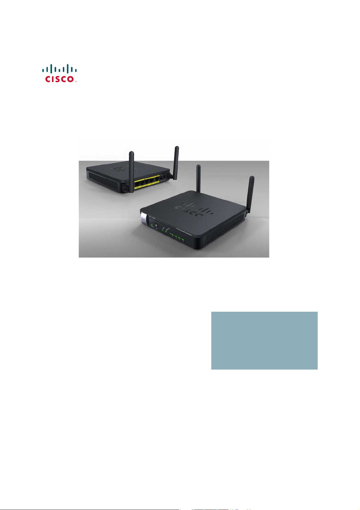
Thank you for choosing the Cisco Small Business RV 110W Wireless-N VPN
Firewall. The Cisco RV 110W is an advanced Internet-sharing network solution for
your small business needs. It allows multiple computers in your office to share an
Internet connection through both wired and wireless connections.
The Cisco RV 110W provides a Wireless-N access point, combined with support
for Virtual Private Networks (VPNs) to make your network more secure. Its 10/100
Ethernet WAN interface connects directly to your broadband DSL or Cable
modem. There are four full-duplex 10/100 Ethernet LAN interfaces that can
connect up to four devices. The wireless access point supports the 802.11n
standard with MIMO technology, which multiplies the effective data rate. This
technology results in better throughput and coverage than provided by 802.11g
networks.
Cisco RV 110W Administration Guide 1
Page 10

Introduction
Product Overview
1
The Cisco RV 110W incorporates a Stateful Packet Inspection (SPI)-based firewall
with Denial of Service (DoS) prevention and a Virtual Private Network (VPN)
engine for secure communication between mobile or remote workers and branch
offices. The Cisco RV 110W supports up to ten gateway-to-gateway IP Security
(IPsec) tunnels to facilitate branch office connectivity through encrypted virtual
links. Users connecting through a VPN tunnel are attached to your company’s
network with secure access to files, e-mail, and your intranet as if they were in the
building. You can also use the VPN capability to allow users on your small office
network to securely connect out to a corporate network
The Cisco RV 110W’s wireless access point supports Wireless Distribution
System (WDS), which allows the wireless coverage to be expanded without wires.
It also supports multiple SSIDs for the use of virtual networks (up to 4 separate
virtual networks), with 802.1Q-based VLAN support for traffic separation. The
Cisco RV 110W implements WPA2-PSK, WPA2-ENT, and WEP encryption, along
with other security features including the disabling of SSID broadcasts, MACbased filtering, and allowing or denying “time of day” access per SSID. The Cisco
RV 110W supports Wi-Fi Multimedia (WMM) and Wi-Fi Multimedia Power Save
(WMM-PS) for wireless Quality of Service (QoS). It supports 802.1p, Differentiated
Services Code Point (DSCP), and Type of Service (ToS) for wired QoS, which can
improve the quality of your network when using delay-sensitive Voice over IP
(VoIP) applications and bandwidth-intensive video streaming applications.
With the Cisco RV 110W’s embedded web server, its settings can be configured
using the browser-based Device Manager. The Cisco RV 110W supports Internet
Explorer, Firefox, and Safari web browsers. The Cisco RV 110W also provides a
setup wizard and VPN wizard. The setup wizard allows you to easily configure the
Cisco RV 110W’s basic settings. You can use the VPN wizard to easily configure
VPN tunnels.
Cisco RV 110W Administration Guide 2
Page 11
Introduction
Getting to Know the Cisco RV 110W
Getting to Know the Cisco RV 110W
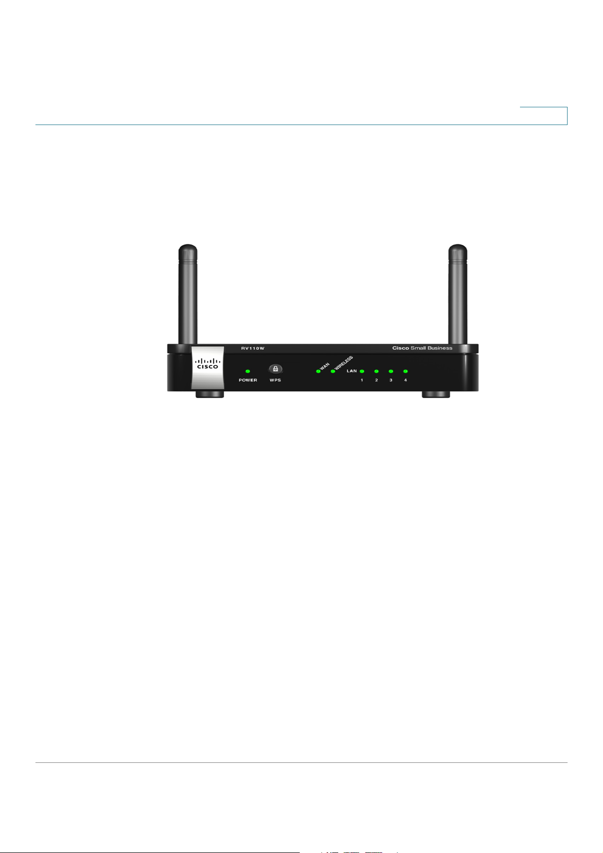
Front Panel
1
POWER—The Power LED lights up green to indicate the device is powered on.
Flashes green when the power is coming on or software is being upgraded.
WAN LED—The WAN (Internet) LED lights up green when the device is connected
to your cable or DSL modem. The LED flashes green when the device is sending or
receiving data over the WAN port.
WIRELESS—The Wireless LED lights up green when the wireless module is
enabled. The LED is off when the wireless module is disabled. The LED flashes
green when the device is transmitting or receiving data on the wireless module.
LAN—These four LEDs correspond to the four LAN (Ethernet) ports of the Cisco
RV 110W. If the LED is continuously lit green, the Cisco RV 110W is connected to a
device through the corresponding port (1, 2, 3, or 4). The LED for a port flashes
green when the Cisco RV 110W is actively sending or receiving data over that
port.
Cisco RV 110W Administration Guide 3
Page 12
Introduction
RESET
RESET
WAN Port
Power Port
Getting to Know the Cisco RV 110W
1
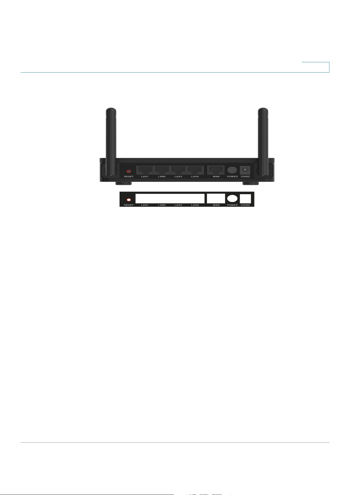
Back Panel
RESET Button—The Reset button has two functions:
• If the Cisco RV 110W is having problems connecting to the Internet, press
the R
This is similar to pressing the reset button on your PC to reboot it.
button for less than five seconds with a paper clip or a pencil tip.
• If you are experiencing extreme problems with the Cisco RV 110W and
LAN Ports (1-4)—These ports provide a LAN connection to network devices,
such as PCs, print servers, or additional switches.
DSL modem.
ON/OFF Power Switch—Press this button to turn the Cisco RV 110W on and off.
When the button is pushed in, power is on.
have tried all other troubleshooting measures, press and hold in the R
button for 10 seconds. This will restore the factory defaults and clear all of
the Cisco RV 110W settings.
—The WAN port is connected to your Internet device, such as a cable or
—The power port is where you connect the AC power cable.
Cisco RV 110W Administration Guide 4
Page 13

Introduction
195114
Wall
mount
slots
2-7/16
Mounting the Cisco RV 110W
Mounting the Cisco RV 110W
You can place your Cisco RV 110W on a desktop or mount it on a wall.
Installation Guidelines
• Ambient Temperature—To prevent the device from overheating, do not
operate it in an area that exceeds an ambient temperature of
104°F (40°C).
• Air Flow—Be sure that there is adequate air flow around the device.
• Mechanical Loading—Be sure that the device is level and stable to avoid
any hazardous conditions.
For desktop placement, place the Cisco RV 110W device horizontally on a flat
surface so that it sits on its four rubber feet.
1
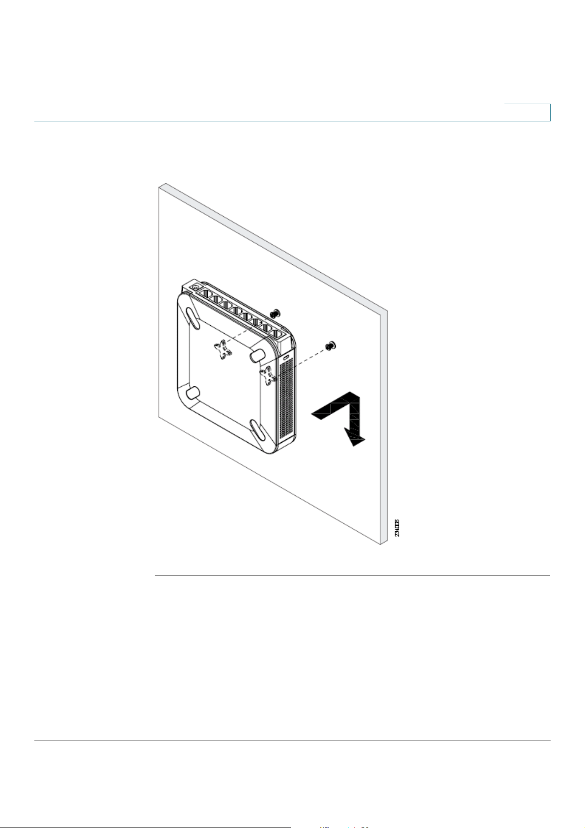
Wall Mounting
STEP 1 Determine where you want to mount the device and install two screws (not
supplied) that are 2-7/16 in. apart (approximately 61 mm). Mounting screws should
have a head that is approximately 5.5 mm in diameter and 2 mm deep, with a shaft
that is at least15.5 mm long and approximately 3.5 mm wide. (Your wall may
require shorter or longer screws, or drywall anchors.)
Do not mount the screw heads flush with the wall; the screw heads must fit inside
the back of the device.
STEP 2 With the back panel pointing up (if installing vertically), line up the device so that
the wall-mount slots on the bottom of the device line up with the two screws.
Cisco RV 110W Administration Guide 5
Page 14
Introduction
Mounting the Cisco RV 110W
1
STEP 3 Place the wall-mount slots over the screws and slide the device down until the
screws fit snugly into the wall-mount slots.
Cisco RV 110W Administration Guide 6
Page 15

Introduction
Connecting the Equipment
Connecting the Equipment
Before you begin the installation, make sure that you have the following equipment
and services:
Required
• Functional Internet Connection (Broadband DSL or cable modem).
• Ethernet cable for WAN (Internet) connection.
• PC with functional network adapter (Ethernet connection) to run the Setup
Wizard or the Device Manager. The Setup Wizard is supported on Microsoft
Windows 2000, Windows XP, Windows Vista, and Windows 7. You must
have Microsoft Core XML Services (MSXML) software installed on the PC to
run the Setup Wizard. MSXML is available from the following location:
http://www.microsoft.com/windows/downloads/
1
The Device Manager is supported on the following web browsers:
- Microsoft Internet Explorer 6.0 and later
- Mozilla Firefox 3.0 and later
- Apple Safari 3.0 or later.
• Ethernet cable (provided) to connect the PC to the router for configuration.
• Software CD containing Setup Wizard (provided).
Optional
• Uninterruptible Power Supply (UPS) to provide backup power to essential
devices (strongly recommended).
• Ethernet cables for LAN interfaces, if you want to connect additional
devices.
Cisco recommends that you use the Setup Wizard to connect and configure your
Cisco RV 110W. If you do not want to use the setup wizard, skip to the “Manually
Connecting Your System” section on page16.
Cisco RV 110W Administration Guide 7
Page 16

Introduction
Start
Next
Back
Install Router
Secure Your
Router Settings
Connecting the Equipment
1
Using the Setup Wizard
Follow these steps to use the Cisco RV 110W Setup Wizard. The Setup Wizard
displays on-screen instructions that guide you through the installation, but you may
find it useful to refer to this document during installation.
NOTE You must connect one PC with an Ethernet cable for the purpose of the initial
configuration. After you complete the initial configuration, administrative tasks can
be performed using a wireless connection.
Starting the Wizard
STEP 1 Make sure that all of the network hardware is powered off, including the
Cisco RV 110W and cable or DSL modem.
STEP 2 Insert the CD that shipped with the Cisco RV 110WRV 110W into the PC you are
using to configure the Cisco RV 110W. The Setup Wizard automatically begins.
STEP 3 Click S
to begin the installation.
STEP 4 Click the check box to accept the software license agreement and click N
STEP 5 The Setup Wizard verifies the network adapter on your PC is functional. If you
receive an error, view your PC’s network connections to make sure the network
adapter is working and click B
Next:
• If your network adapter is functional and you have not yet connected your
hardware, the
Hardware, page 9.)
• If your network adapter is functional, you have already connected your
hardware, and your Internet connection has been detected, the S
window appears. (See Configuring Security, page 14.)
to test the connection again.
window appears. (See Connecting Your
.
Cisco RV 110W Administration Guide 8
Page 17
Introduction
Next
Connecting the Equipment
1
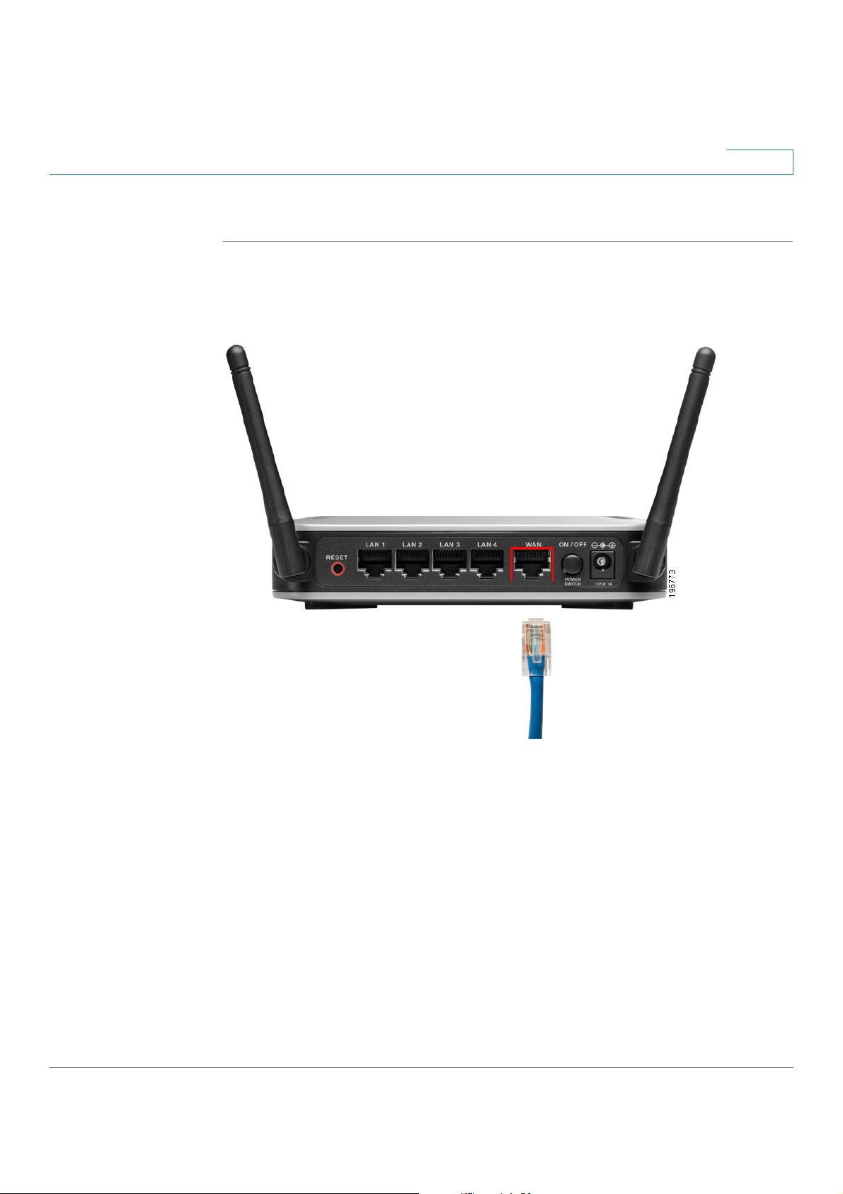
Connecting Your Hardware
STEP 1 You should have an Ethernet cable connecting your PC to the cable or DSL
modem. Unplug one end of the cable from your PC and plug it into the port marked
“WAN” on the device. Click N
.
Cisco RV 110W Administration Guide 9
Page 18
Introduction
Next
Connecting the Equipment
1
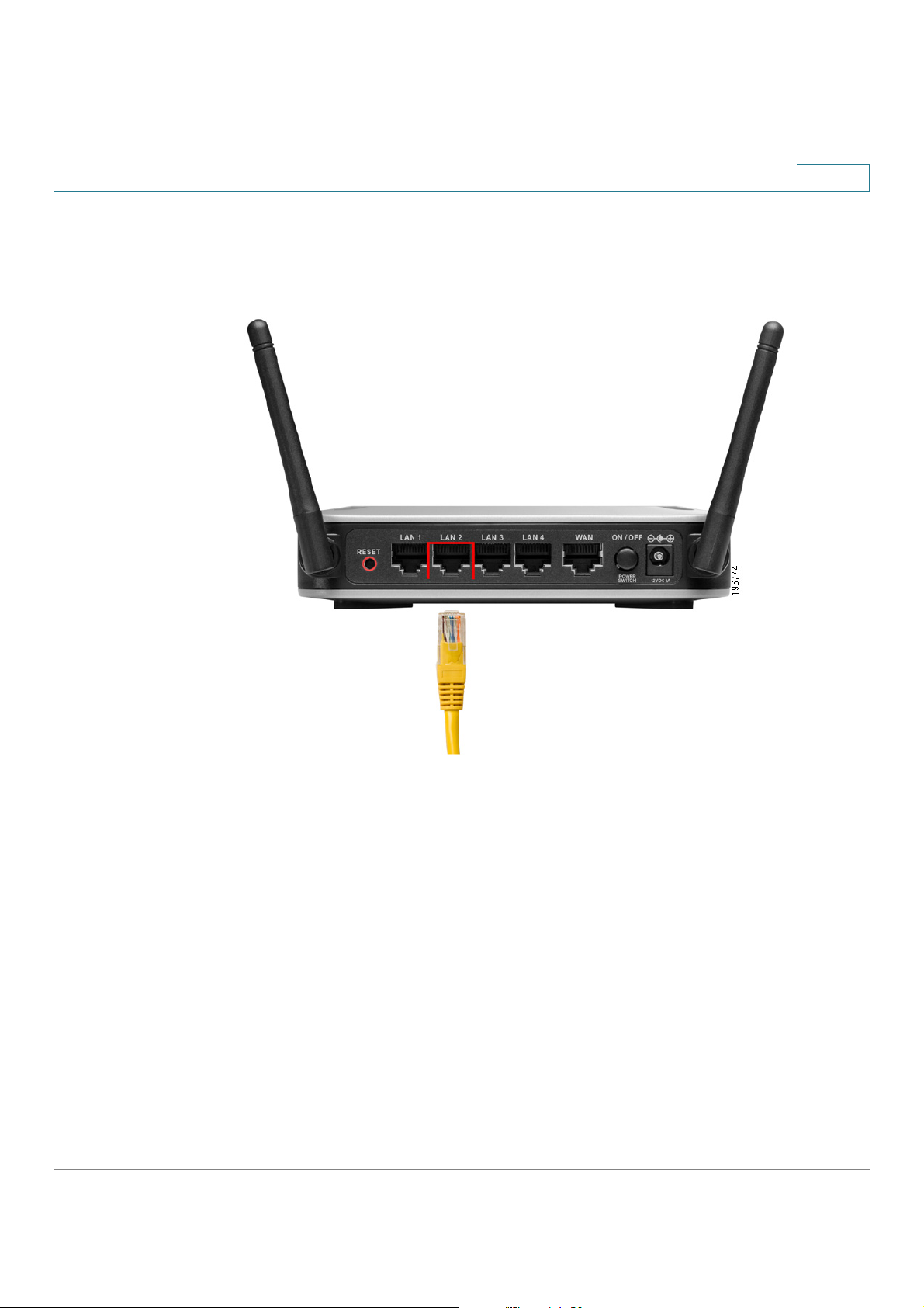
STEP 2 Connect one end of a different Ethernet cable to one of the LAN (Ethernet) ports on
the back of the device. (In this example, the LAN 2 port is used.) Connect the other
end to an Ethernet port on the PC that is running the Setup Wizard. Click N
.
STEP 3 Power on the cable or DSL modem and wait until the connection is active.
Cisco RV 110W Administration Guide 10
Page 19
Introduction
Next
!
Connecting the Equipment
1
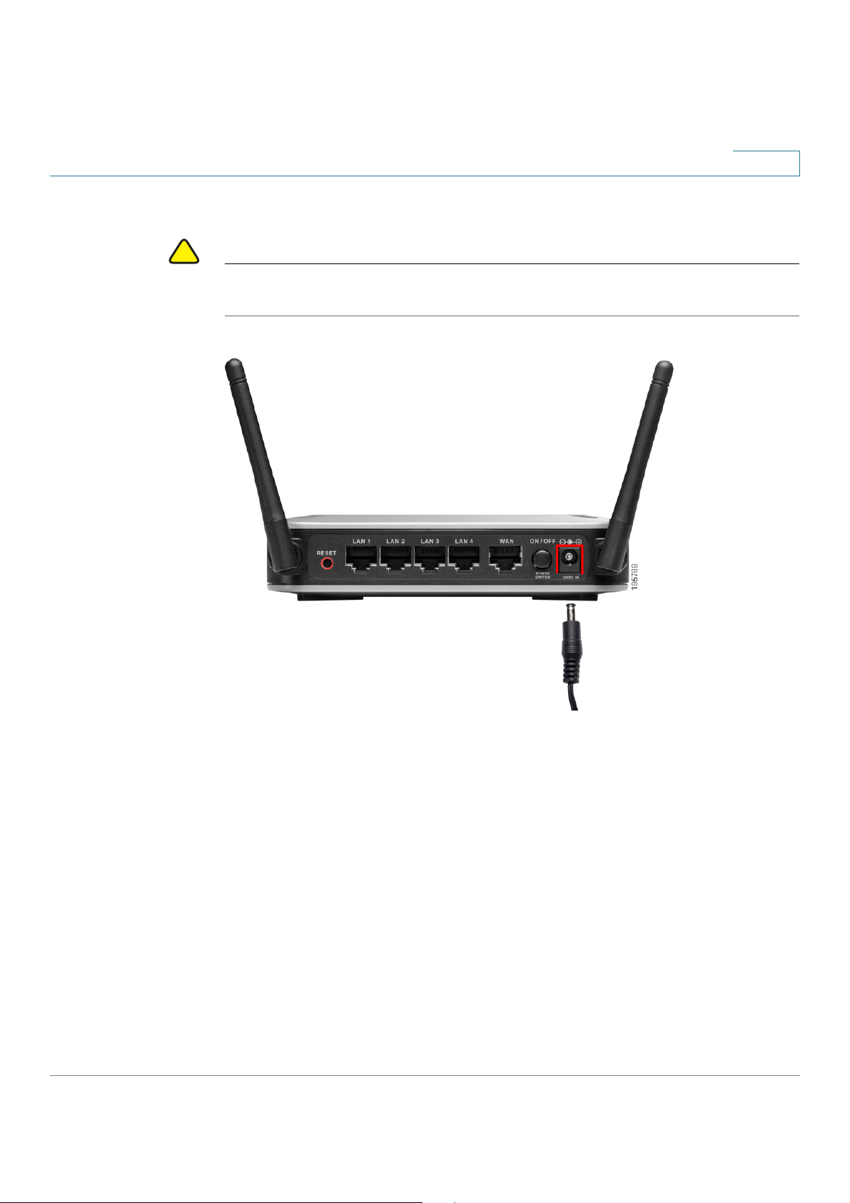
STEP 4 Connect the power adapter to the Cisco RV 110W power port. Click N
CAUTION Use only the power adapter that is supplied with the device. Using a different
power adapter could damage the device.
.
STEP 5 Plug the other end of the adapter into an electrical outlet.
Cisco RV 110W Administration Guide 11
Page 20
Introduction
Enter Username and
Password
Configure Router
Connecting the Equipment
1
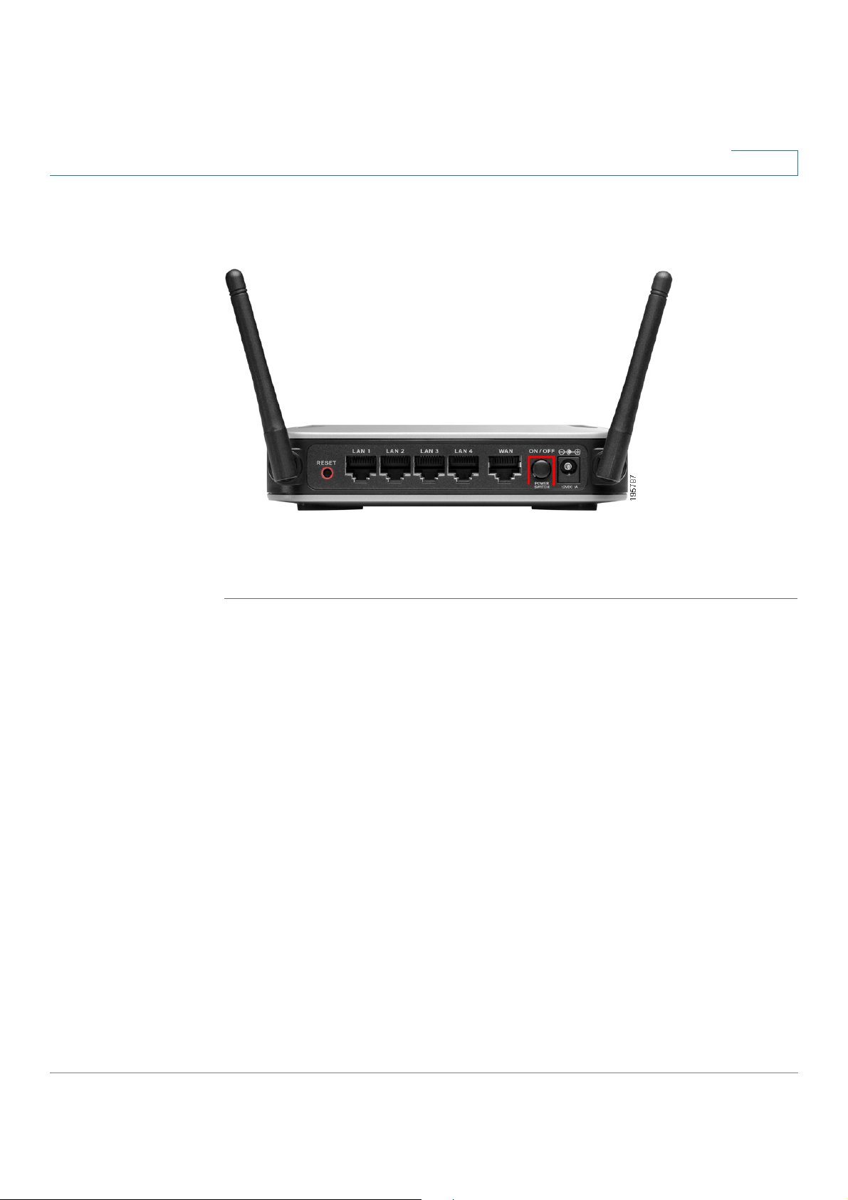
STEP 6 On the Cisco RV 110W, push in the ON/OFF POWER SWITCH button. The Setup
Wizard searches for the Cisco RV 110W.
The POWER LED on the front panel lights up green when the power adapter is
connected properly and the device is turned on.
Next:
• If your hardware connection is successful, but the Setup Wizard needs
more information about your Internet connection, the E
window appears. (See Entering Login and Internet Connection
Information, page 13.)
• If your hardware connection is successful and the Setup Wizard
successfully detects your Internet connection, the C
window displays. (See Configuring Security, page 14.)
Cisco RV 110W Administration Guide 12
Page 21

Introduction
admin
Next
Next
Dynamic (DHCP)
Static IP Connection
PPPoE
PPTP
LT2P
Next
Dynamic (DHCP)
Static IP Connection
Next
PPPoE
Next
Connecting the Equipment
1
Entering Login and Internet Connection Information
STEP 1 Enter the username and password for your Cisco RV 110W. The default username
and password are both a
STEP 2 Choose your Internet connection type:
• Telephone (DSL)
• Cable broadband
• I don’t know
Click N
STEP 3 The Setup Wizard confirms your Internet connection settings. If it cannot detect or
confirm your settings, you might need to provide information about your Internet
connection type. You can get this information from your ISP.
The types of Internet connections are:
•
.
modem. This address can change.
. Click N
—Your PC receives its IP address from your cable or DSL
.
•
an IP address that does not change. You will need this address and some
additional information (see Step 4) to proceed with installation.
•
with asymmetric DSL).
•
Europe).
•
After selecting your connection type, click N
STEP 4 If you chose:
•
•
Gateway IP, DNS, and secondary DNS (optional). This information comes
from your ISP. Click N
•
password. Click N
—Your Internet Service Provider (ISP) has assigned you
—You have a point-to-point connection to the Internet (used mainly
—Your provider uses point-to-point tunneling protocol (used in
—Your provider uses layer 2 tunneling protocol (used in Europe).
.
—Proceed to Step 5.
—Provide your Static IP Address, Subnet Mask,
after entering the information.
—Provide your account name (for example,
after entering the information.
john@ISPname.net
), and
Cisco RV 110W Administration Guide 13
Page 22

Introduction
PPTP (Europe)
Next
L2TP (Europe)
Next
Next
Next
Next
Next
Connecting the Equipment
1
•
—Provide your account name (for example,
john@ISPname.net
entering the information.
•
john@ISPname.net), password, and server IP address. Click N
entering the information.
STEP 5 The Setup Wizard configures your connection, verifies the router settings, and
checks the network connection. Click N
STEP 6 To configure your home network, click N
—Provide your account name (for example,
), password, and server IP address. Click N
.
.
after
after
Configuring Security
STEP 1 Enter a new Cisco RV 110W administration password and click N
reasons, you should not use the default password. Follow these password
guidelines:
• Passwords should not contain dictionary words from any language or the
default password.
. For security
• Passwords should contain a mix of letters (both upper- and lowercase),
numbers, and symbols.
• Passwords must be at least 8 but no more than 30 characters.
• Password security ratings are shown to the right of the password you enter,
and are rated from weak to secure. Cisco recommends using a password
rated as secure.
STEP 2 Enter a name (SSID) for your wireless network and click N
the default SSID to a unique name. The SSID is case-sensitive.
NOTE For added security, disable broadcasting of the SSID. You can disable SSID
broadcast using the Device Manager; see Editing an AP’s Properties, page 67.
. You should change
Cisco RV 110W Administration Guide 14
Page 23

Introduction
Next
Next
Next
Yes
Connecting the Equipment
1
STEP 3 Select the type of security to use:
Best Security (WPA2)
Strong wireless security that uses a password (security key) to protect your
network. Recommended for most networks. The devices you connect to your
wireless network must support WPA2; see the support information for your device
if you have questions.
a. Enter a security key (must be at least 8 and no more than 63 characters) or use
the randomly-generated one provided by the Cisco RV 110W. Keys should
contain a mix of letters (both upper- and lowercase), numbers, and symbols.
Security key ratings are shown to the right of the password you enter, and are
rated from weak to secure. Cisco recommends using a password rated as
secure.
b. Click N
Better Security (WPA)
Wireless security that uses a password (security key) to protect your network. It is
less secure than WPA2, but it is supported by older devices. If the devices you are
connecting to your wireless network do not support WPA2, choose this option.
.
a. Enter a security key (must be at least 8 and no more than 63 characters) or use
the randomly-generated one provided by the Cisco RV 110W. Keys should
contain a mix of letters (both upper- and lowercase), numbers, and symbols.
Security key ratings are shown to the right of the password you enter, and are
rated from weak to secure. Cisco recommends using a password rated as
secure.
b. Click N
No Security
This option is not recommended; it allows devices to connect to your wireless
network if the network name is known.
a. Click N
b. Click Y
.
.
when the warning message is displayed.
Cisco RV 110W Administration Guide 15
Page 24

Introduction
Print these settings
Next
OK
Next
Finish
Connecting the Equipment
1
STEP 4 The security settings for your network are shown. To save these settings in a text
file on your PC, check the box provided. To print, click P
to confirm these settings. (If you chose to save these settings to your
desktop, then click O
NOTE You must enter this security information on each device that connects to your
network. Save this information!
STEP 5 The Cisco RV 110W configures your connection and displays a status message if
the configuration is successful. Click N
STEP 6 The Cisco RV 110W displays a message if it has been configured and is
successfully connected to the Internet. Click F
. Click
.)
.
.
Manually Connecting Your System
Use these procedures if you do not want to use the Setup Wizard.
NOTE You must connect one PC with an Ethernet cable for the purpose of the initial
configuration. After you complete the initial configuration, administrative tasks can
be performed using a wireless connection.
STEP 1 Connect your equipment as described in “Connecting Your Hardware” section
on page 9.
STEP 2 Connect to the Device Manager to view and configure your Cisco RV 110W
settings. When you connect to the Device Manager, the Getting Started page
shows links that you can click to perform basic tasks. At a minimum, we
recommend that you:
• Change the Cisco RV 110W password (see Configuring User Accounts,
page 127.)
• Review wireless profile and set security settings (see Configuring the
Wireless Radio Properties, page 70.)
Cisco RV 110W Administration Guide 16
Page 25

Introduction
Network
Connections
Network and Internet
Verifying the Hardware Installation
1
See the “Getting Started in the Cisco RV 110W Device Manager” section on
page18 for more information.
Verifying the Hardware Installation
To verify the hardware installation, complete the following tasks:
• Check the LED states, as described in Getting to Know the Cisco RV
110W, page 3.
• Connect a PC to an available LAN port and verify that you can connect to a
website on the Internet, such as www.cisco.com.
• Configure a device to connect to your wireless network and verify the
wireless network is functional. See Connecting to Your Wireless Network,
page17.
Connecting to Your Wireless Network
To connect a device (such as a PC) to your wireless network, you must configure
the wireless connection with the security information you entered when you used
the Setup Wizard or that you configured using the Device Manager.
The following steps are provided as an example; you may need to configure your
device differently. For instructions that are specific to your device, consult the user
documentation for your device.
STEP 1 Open the wireless connection settings window or program for your device. Your
PC may have special software installed to manage wireless connections, or you
may find wireless connections under the Control Panel in the N
or N
operating system.)
STEP 2 Enter the network name (SSID) you chose for your network when you configured
the Cisco RV 110W.
window. (The location depends on your
Cisco RV 110W Administration Guide 17
Page 26

Introduction
http://192.168.1.1
Enter
Getting Started in the Cisco RV 110W Device Manager
1
STEP 3 Choose the type of encryption and enter the security key that you chose when
setting up the Cisco RV 110W. If you did not enable security (not recommended),
leave these fields blank.
STEP 4 Verify your wireless connection and save your settings.
Getting Started in the Cisco RV 110W Device Manager
The Device Manager allows you to configure and manage your Cisco RV 110W,
including the following tasks:
• View system status information
• Configure local and wide-area network settings
• Configure wireless security, firewall, and VPN settings
• Configure quality of service
• Perform software upgrades
Logging In
To use the Device Manager:
STEP 1 On a PC connected to a LAN port on the back panel of the Cisco RV 110W, start
your web browser. (If you have performed the initial configuration using the Setup
Wizard, you can connect using the Cisco RV 110W’s wireless connection.)
STEP 2 To connect to the Device Manager, enter
in your browser’s address field, and press E
request page appears.
NOTE The default IP address is 192.168.1.1. If there is another device connected to
the network that is acting as a DHCP server, that device may assign a
different address to the Cisco RV 110W. You must use the assigned IP
address to connect to the Cisco RV 110W.
. A password
Cisco RV 110W Administration Guide 18
Page 27

Introduction
admin
admin
Log In
Support
Forums
Don’t show this on start-up
Getting Started in the Cisco RV 110W Device Manager
1
STEP 3 In the Username and Password fields, enter the default user name (which is a
and password (which is also a
), in lowercase letters. Then click L
.
Using the Getting Started Page
The Getting Started page displays some of the most common configuration tasks.
Click these underlined tasks to view the configuration windows. You can access
the following tasks from the Getting Started page:
Initial Settings
• Change Default Administrator Password—See Configuring User
Accounts, page 127.
• Configure WAN Settings—See Configuring the WAN for an IPv4
Network, page 30.
• Configure LAN Settings—See Configuring the Local Area Network (LAN),
page 36.
• Review Wireless Profile and Set Security Settings—See Configuring
Access Points, page 66.
)
• Add VPN Clients—See Configuring IPsec Users, page 114.
Quick Access
• Upgrade Device Software—See Upgrading Firmware, page138.
• Configure Site to Site VPN—See Using the VPN Wizard, page 102.
• Configure Remote Management Access—See Configuring Remote
Management, page 98.
Device Status
• System Summary—See Viewing Device Statistics, page 22.
• Wireless Status—See Viewing the Wireless Status, page 25.
• VPN Status—See Viewing the IPsec Connection Status, page 26.
To get support for your device, click the S
visit the online support forums, click F
To prevent the Getting Started page from showing when the Device Manager is
started, check the D
link at the bottom of the page. To
.
box.
Cisco RV 110W Administration Guide 19
Page 28
Introduction
Getting Started in the Cisco RV 110W Device Manager
1
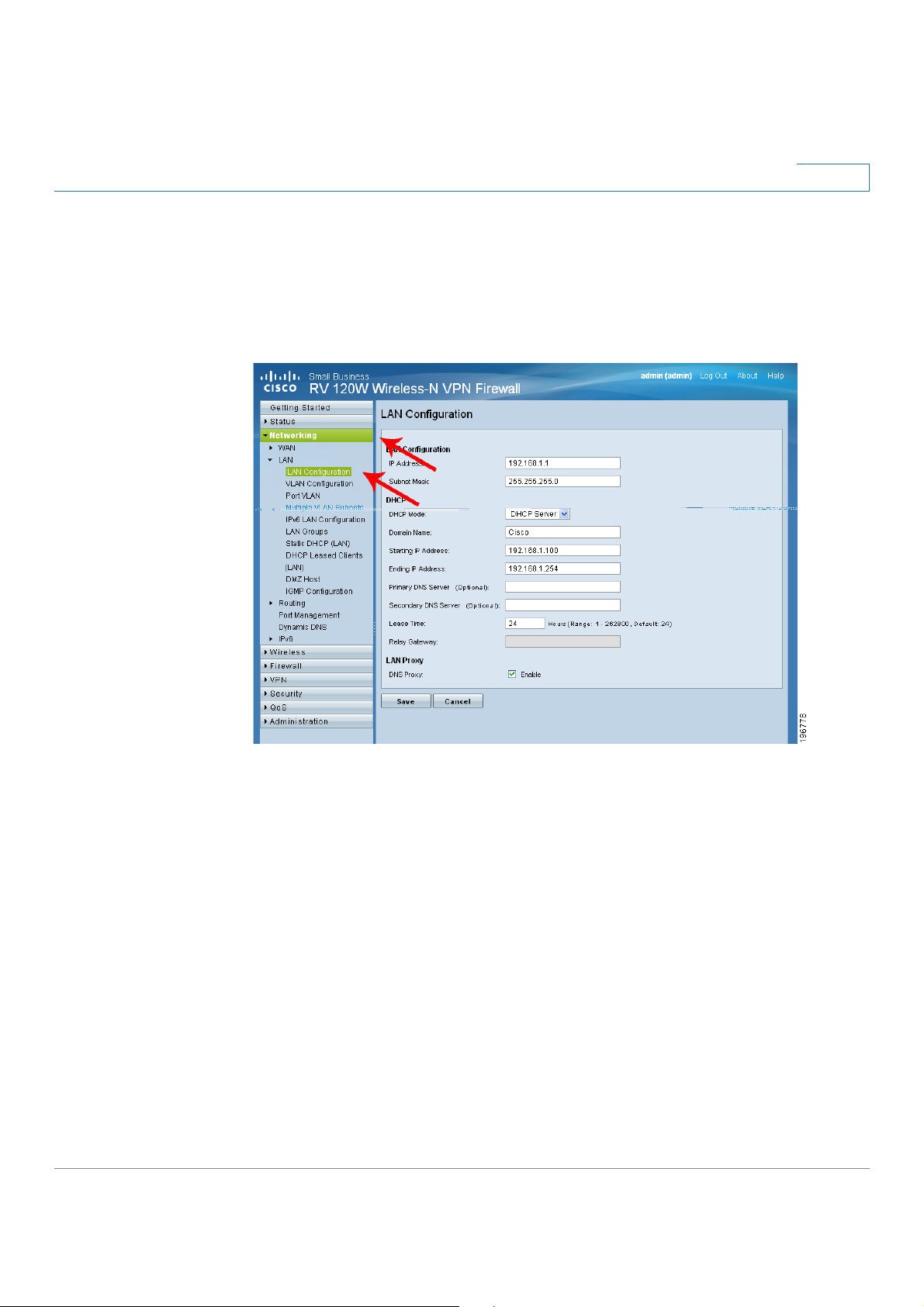
Navigating through the Pages
Use the navigation tree in the left pane to open the configuration pages. Click a
menu item on the left panel to expand it. Click the menu names displayed
underneath to perform an action or view a sub-menu.
Cisco RV 110W Administration Guide 20
Page 29
Introduction
Save
Cancel
Getting Started in the Cisco RV 110W Device Manager
1
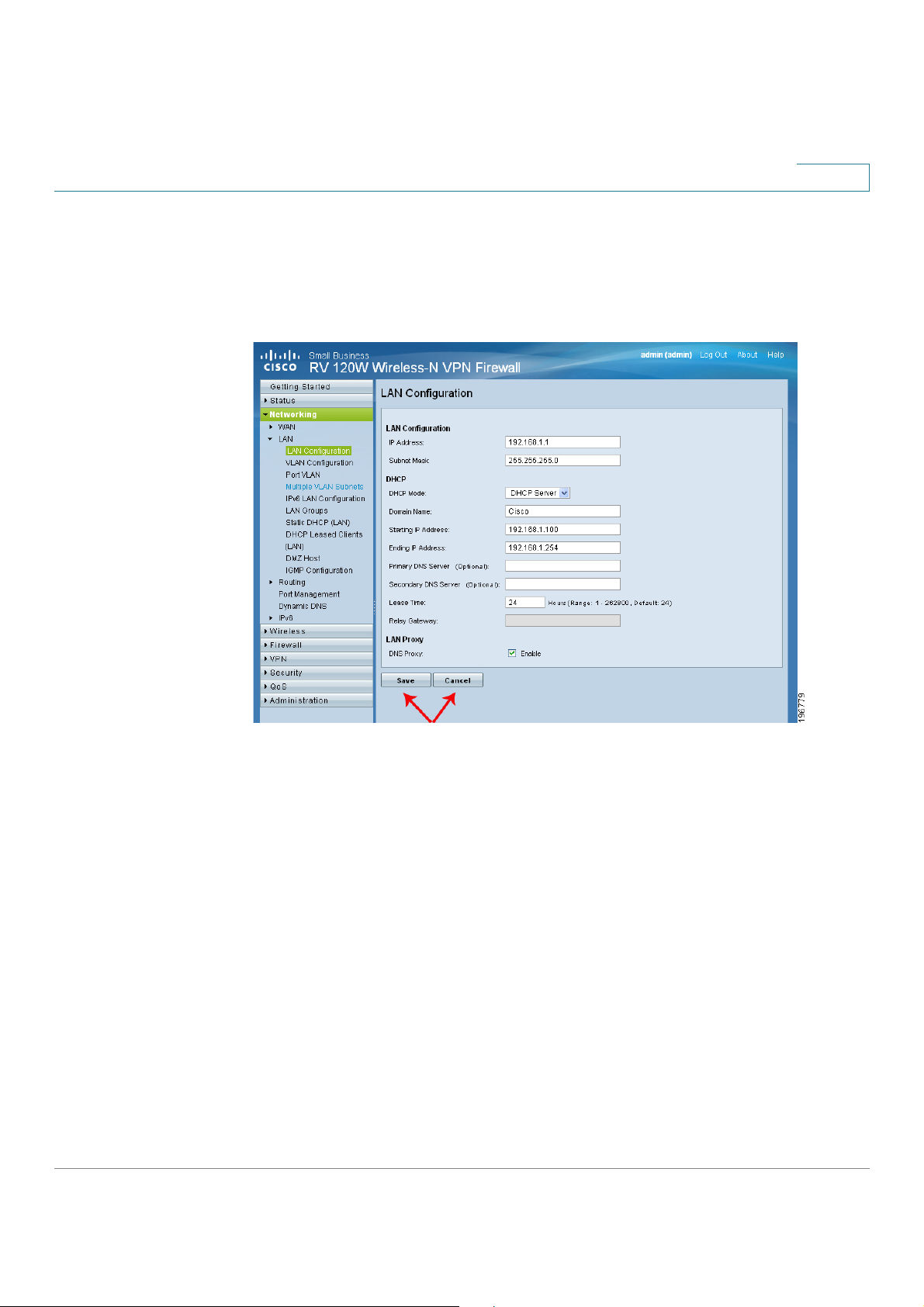
Saving Your Changes
When you finish making changes on a configuration page, click S
changes, or click C
to undo your changes.
to save the
Cisco RV 110W Administration Guide 21
Page 30
Introduction
Help
Status
Status
System Summary
Refresh
System Name
Firmware Version
Viewing Device Statistics
1
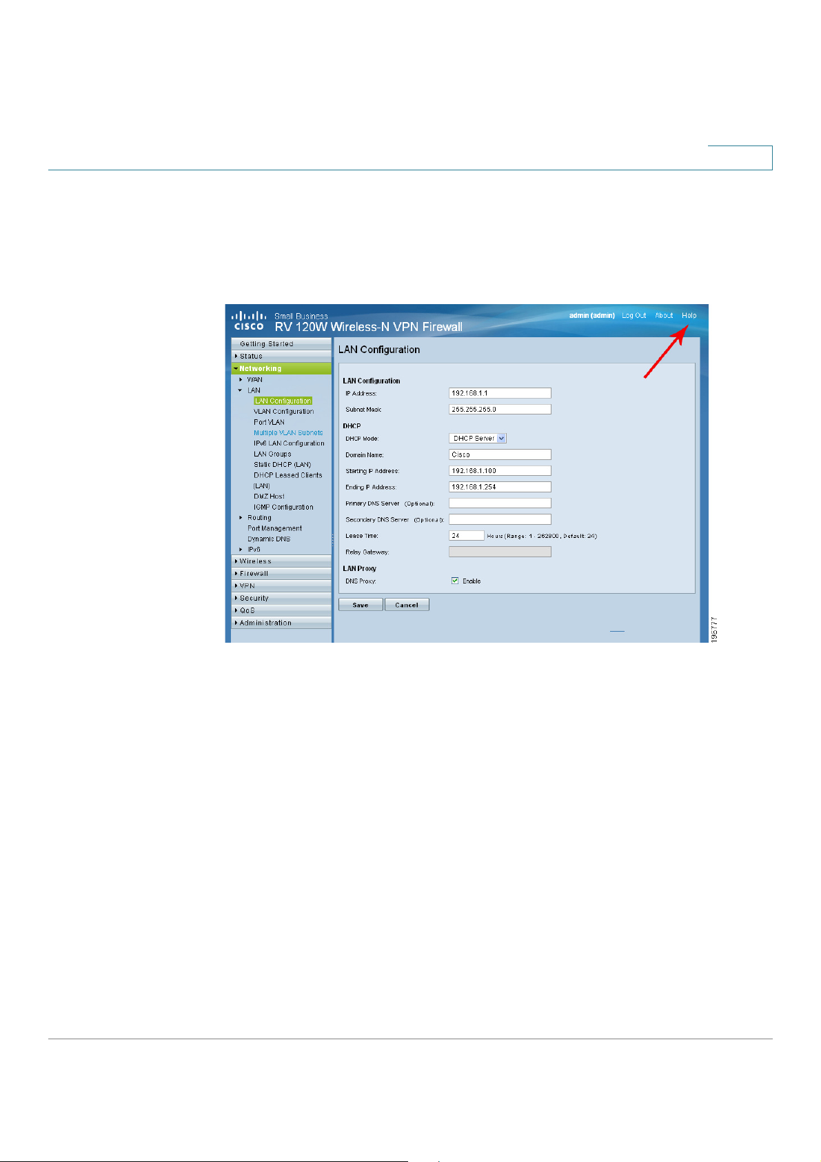
Viewing the Help Files
To view more information about a configuration page, click the H
top right corner of the page.
link near the
Viewing Device Statistics
The Cisco RV 110W provides real-time statistics for the device. To access
statistics, in the Device Manager, choose S
Viewing the System Summary
To view the system summary, choose S
refresh the information and obtain the latest information.
The system summary page displays the following:
•
•
Cisco RV 110W Administration Guide 22
—Name of the device.
—Current software version the device is running.
.
> S
. Click R
to
Page 31

Introduction
Firmware MD5 Checksum
PID VID
CPU Usage
Memory Usage
MAC Address
IPv4 Address
IPv6 Address
DHCP Server
DHCP Relay
DHCPv6 Server
DHCPv6 Server
MAC Address
Connection Time
Viewing Device Statistics
1
•
the integrity of files.
•
•
•
LAN Information
•
•
•
is enabled).
•
If it is enabled, DHCP client machines connected to the LAN port receive
their IP address dynamically.
•
must be enabled).
—Product ID and vendor ID of the device.
—The message-digest algorithm used to verify
—Percentage of CPU currently used.
—Percentage of memory currently used.
—Hardware address.
—Address and subnet mask of the device.
—Address and subnet mask of the device (shown only if IPv6
—Indicates if the device’s DHCP server is enabled or disabled.
—Indicates if the device is acting as a DHCP relay (DHCP relay
•
disabled. If it is enabled, DHCPv6 client machines connected to the LAN
port receive their IP address dynamically.
•
disabled. If it is enabled, DHCP client machines connected to the LAN port
receive their IP address dynamically.
WAN Information
The WAN Information provides the current status of the WAN interfaces. It
provides details about WAN interface and also provides actions that can be taken
on that particular WAN interface. The actions that can be taken differ with the
connection type. If WAN is configured using DHCP, the DHCP release renew
options are available, other connection types offer other options. The Dedicated
WAN Info displays information about the WAN port.
•
•
up.
: Indicates if the device’s DHCPv6 server is enabled or
—Indicates if the device’s DHCPv6 server is enabled or
—MAC Address of the WAN port.
—Displays the time duration for which the connection is
Cisco RV 110W Administration Guide 23
Page 32

Introduction
Connection Type
Connection State
IP Address
Subnet Mask
NAT
Gateway
Primary DNS
Secondary DNS
NAT (IPv4 Only Mode)
DHCP Server
Lease Obtained
Lease Duration
Renew
Release
Country
Operating Frequency
Wireless Network Mode
Channel
Viewing Device Statistics
1
•
dynamically through a DHCP server, assigned statically by the user, or
obtained through a PPPoE/PPTP/L2TP ISP connection.
•
Service Provider.
•
•
•
•
•
•
•
If connection is DHCP Enabled:
—Indicates if the security appliance is in NAT mode (enabled) or routing
mode (disabled).
(enabled) or routing mode (disabled).
—IP address of the WAN port.
—Subnet Mask for the WAN port.
—Gateway IP address of the WAN port.
—Primary DNS server IP address of the WAN port.
—Indicates if the WAN IPv4 address is obtained
—Indicates if the WAN port is connected to the Internet
—Secondary DNS server IP address of the WAN port.
—Indicates if the security appliance is in NAT mode
•
port is connected.
•
DHCP server.
•
active.
Click R
release the current IP address only.
Wireless Information
This section displays information about the Wireless Radio settings.
•
•
•
•
to release the current IP address and obtain a new one, or R
example, N or N/G,).
—Indicates the IP address of the DHCP server to which WAN
—Indicates the time at which lease is obtained from the
—Indicates the duration for which the lease would remain
—Displays the country for which the radio is configured.
—Displays the operational frequency band.
—Displays the Wi-Fi™ mode of the radio (for
—Displays the current channel in use by the radio.
to
Cisco RV 110W Administration Guide 24
Page 33

Introduction
SSID
BSSID
Profile Name
Security
Encryption
Authentication
Packets
Bytes
Errors
Dropped
Viewing Device Statistics
1
Available Access Points Table
The table displays the list of Access Points currently enabled in the device. The
table also displays information related to the Access Point, such as Security and
Encryption methods used by the Access Point.
•
•
•
•
•
•
—This is the Service Set Identifier (SSID) that clients use to connect to
the AP that has this profile. It is referenced in the AP tables and statistics.
the Access Point belongs.
profile attached to the Access Point.
to this profile.
profile: TKIP, AES, TKIP + AES.
configured in the profile: PSK, RADIUS, PSK + RADIUS.
—The 48 bit unique identifier of the Basic Service Set (BSS) to which
—This is the unique (alphanumeric) identifier of the wireless
—This field displays the type of wireless security (if any) assigned
—This field displays the encryption type that is assigned to the
—This field displays the client authentication method that is
Viewing the Wireless Status
This page shows a cumulative total of relevant wireless statistics for the radio and
APs configured on the device. The counters are reset when the device is
rebooted.
Radio Statistics
A given radio can have multiple virtual APs (VAPs) configured and active
concurrently. This table indicates cumulative statistics for the available radio(s).
•
reported to the radio, over all configured APs.
•
reported to the radio, over all configured APs.
•
to the radio, over all configured APs.
•
the radio, over all configured APs.
—The number of transmitted/received (tx/rx) wireless packets
—The number of transmitted/received (tx/rx) bytes of information
—The number of transmitted/received (tx/rx) packet errors reported
—The number of transmitted/received (tx/rx) packets dropped by
Cisco RV 110W Administration Guide 25
Page 34

Introduction
Multicast
Collisions
AP Name
Packets
Bytes
Errors
Dropped
Multicast
Collisions
Poll Interval
Stop
Start
Policy Name
Endpoint
Tx KB
Tx Packets
State
Not
Connected
IPsec SA Established.
Viewing Device Statistics
1
•
•
AP Statistics
This table displays transmit/receive data for a given AP.
•
•
the AP.
•
the AP.
•
to the AP.
•
the AP.
•
•
•
page to re-read the statistics from the router and refresh the page
automatically. To modify the poll interval, click the S
—The number of multicast packets sent over this radio.
—The number of packet collisions reported to the AP.
—The name of the AP.
—The number of transmitted/received (tx/rx) wireless packets on
—The number of transmitted/received (tx/rx) bytes of information on
—The number of transmitted/received (tx/rx) packet errors reported
—The number of transmitted/received (tx/rx) packets dropped by
—The number of multicast packets sent over this AP.
—The number of packet collisions reported to the AP.
—Enter a value in seconds for the poll interval. This causes the
to restart automatic refresh.
button and then click
Viewing the IPsec Connection Status
This page displays the status of IPSec connections. You can change the status of a
connection to either establish or disconnect the configured SAs (Security
Associations).
Cisco RV 110W Administration Guide 26
•
•
•
•
•
—The name of the IKE or VPN policy associated with this SA.
—Displays the IP address of the remote VPN gateway or client.
—The data transmitted (in KB) over this SA.
—The number of IP packets transmitted over this SA.
—The current status of the SA for IKE policies. The status can be N
or I
Page 35

Introduction
Connect
Drop
Stop
Start
Username
Remote IP
Status
Drop
Stop
Start
Facility
Viewing Device Statistics
1
Click C
active SA (connection).
The page refreshes automatically to display the most current status for an SA. To
change the refresh settings, in the Poll Interval field, enter a value in seconds for
the poll interval. This causes the page to re-read the statistics from the router and
refresh the page automatically. To modify the poll interval, click the S
and click S
Viewing the QuickVPN Connection Status
This page displays the status of QuickVPN connections and allows you to DROP
any existing active (ONLINE) connections.
•
tunnel.
•
could be NAT/Public IP if the client is behind the NAT router.
•
QuickVPN tunnel is NOT initiated/established by the IPSec user. ONLINE
means that QuickVPN Tunnel, initiated/established by the IPSec user, is
active.
to establish an inactive SA (connection) or D
to restart automatic refresh.
—The name of the IPSec User associated with the QuickVPN
—Displays the IP address of the remote QuickVPN client. This
—Displays the current status of QuickVPN client. OFFLINE means that
to terminate an
button
Click D
QuickVPN client to OFFLINE.
The page refreshes automatically to display the most current status for QuickVPN
users. To change the refresh settings, in the Poll Interval field, enter a value in
seconds for the poll interval. This causes the page to re-read the statistics from the
router and refresh the page automatically. To modify the poll interval, click the S
button and click S
Viewing Logs
This window displays the system event log, which can be configured to log login
attempts, DHCP server messages, reboots, firewall messages and other
information.
•
to terminate an active/ONLINE connection and change the status of
to restart automatic refresh.
—From the drop-down list, select the type of logs to display: All,
Kernel, System, IPSec VPN, Local0-Wireless.
- Kernel logs are those that are a part of the kernel code (for example,
firewall).
Cisco RV 110W Administration Guide 27
Page 36

Introduction
Refresh Logs
Clear Logs
Send Logs
Send Log
Administration
Logging
Remote Logging
LAN IP Address
Open Ports
Time Remaining Seconds
Refresh
Viewing Device Statistics
1
- System logs are those that are a part of user-space applications (for
example, NTP, Session, DHCP).
- IPSec VPN logs are those related to ipsec negotiations. These are
related user space logs. Local0-Wireless are those related to wireless
connection and negotiation.
Click R
to delete all entries in the log window.
Click S
Before clicking S
are configured on the A
Viewing Available LAN Hosts
This page shows available LAN hosts.
to view the entries added after the page was opened. Click
to e-mail the log messages currently displayed in the log window.
, ensure that the e-mail address and server information
> L
> R
page.
Viewing the Port Triggering Status
The Port Triggering Status page provides information on the ports that have been
opened per the port triggering configuration rules. The ports are opened
dynamically whenever traffic that matches the port triggering rules flows through
them. The table displays the following fields:
•
the ports to be opened.
•
WAN destined to the LAN IP address can flow through the router.
•
will remain open when there is no activity on that port. The time is reset
when there is activity on the port.
Click R
Viewing Port Statistics
This table displays the data transfer statistics for the Dedicated WAN, LAN, and
WLAN ports, including the duration for which they were enabled. The following
data is displayed:
Cisco RV 110W Administration Guide 28
to refresh the current page and obtain the latest statistics.
—Displays the LAN IP address of the device which caused
—Displays the ports that have been opened so that traffic from
—This field displays the time for which the port
Page 37

Introduction
Tx Packets
Rx Packets
Collisions
Tx B/s
Rx B/s
Uptime
Poll Interval
Stop
Start
Viewing Device Statistics
1
•
•
•
A collision occurs when the port tries to send data at the same time as a
port on another router or computer that is connected to this port.
•
•
•
reset to zero when the router or the port is restarted.
re-read the statistics from the router and refresh the page automatically. To modify
the poll interval, click the S
—The number of IP packets going out of the port.
—The number of packets received by the port.
—The number of signal collisions that have occurred on this port.
—The number of bytes going out of the port per second.
—The number of bytes received by the port per second.
—The duration for which the port has been active. The uptime is
—Enter a value in seconds for the poll interval. This causes the page to
button and then S
to restart automatic refresh.
Cisco RV 110W Administration Guide 29
Page 38

Configuring Networking
The networking page allows you to configure networking settings. This chapter
contains the following sections:
• Configuring the Wide Area Network (WAN), page 30
• Configuring the Local Area Network (LAN), page 36
• Configuring Routing, page 48
• Configuring Routing, page 48
• Configuring Dynamic DNS (DDNS), page 53
2
• Configuring IPv6, page 54
Configuring the Wide Area Network (WAN)
Wide area network configuration properties are configurable for both IPv4 and
IPv6 networks. You can enter information about your Internet connection type and
other parameters in these pages.
Configuring the WAN for an IPv4 Network
Configuring WAN properties for an IPv4 network differs depending on which type
of Internet connection you have. See the sections below for detailed instructions.
Configuring the Internet Connection Type
NOTE If your Internet connection does not require a login, you do not need to configure the
ISP Connection Type fields.
Cisco RV 120W Administration Guide 30
Page 39

Configuring Networking
Networking
WAN
IPv4 WAN Configuration
Internet Connection Requires a Login
WAN
PPPoE
Profiles
MPPE
Encryption
Keep connected
Connect on demand
Idle Time
My IP Address
Server IP Address
Configuring the Wide Area Network (WAN)
2
STEP 1 Choose N
STEP 2 If you connect to the Internet using one of the following connection types, check
the I
STEP 3 Choose your ISP Connection Type:
PPPoE
a. First, create a PPPoE Profile. See “Creating PPPoE Profiles” on page 35.
b. Under PPPoE Profile Name, select the profile you created on the W
c. Go to “Configuring Maximum Transmit Unit (MTU)” on page 33.
PPTP
• Point-to-Point Protocol over Ethernet (PPPoE)—used mainly with
asymmetric DSL.
• Point-to-Point Tunneling Protocol (used in Europe).
• Layer 2 Tunneling Protocol (used in Europe).
page. The username, password, and other fields are entered
automatically.
> W
> I
box:
.
> P
a. Provide your username and password. These are assigned to you by the ISP to
access your account.
b. If your ISP supports Microsoft Point-to-Point encryption, check the M
box.
c. Choose the connectivity type:
•
•
present. If the connection is idle—that is, no traffic is occurring—the
connection is closed. You might want to choose this if your ISP charges
based on the amount of time that you are connected.
If you choose this connection type, enter the number of minutes after which
the connection shuts off in the I
d. Enter the IP address assigned to you by your ISP in the M
e. Enter the IP address of your ISP’s server in the S
f. Go to “Configuring Maximum Transmit Unit (MTU)” on page 33.
—The Internet connection is always on.
—The Internet connection is on only when traffic is
field.
field.
field.
Cisco RV 120W Administration Guide 31
Page 40

Configuring Networking
Keep connected
Connect on demand
Idle Time
My IP Address
Server IP Address
Save
Get Dynamically From ISP
Use Static IP Address
Save
Configuring the Wide Area Network (WAN)
2
L2TP
a. Provide your username and password. These are assigned to you by the ISP to
access your account.
b. Enter your secret phrase. This phrase is known to you and your ISP for use in
authenticating your logon.
c. Choose the connectivity type:
•
•
present. If the connection is idle—that is, no traffic is occurring—the
connection is closed. You might want to choose this if your ISP charges
based on the amount of time that you are connected.
If you choose this connection type, enter the number of minutes after which
the connection shuts off in the I
d. Enter the IP address assigned to you by your ISP in the M
e. Enter the IP address of your ISP’s server in the S
f. Click S
on page 33.
. If applicable, go to “Configuring Maximum Transmit Unit (MTU)”
—The Internet connection is always on.
—The Internet connection is on only when traffic is
field.
field.
field.
Configuring Internet Address Information
STEP 1 If your ISP uses Dynamic Host Control Protocol (DHCP) to assign you an IP
address, you receive a dynamic IP address that is newly generated each time you
log in. In the IP Address Source field, choose
If your ISP has assigned you a static (non-changing) IP address, in the IP Address
Source Field, choose U
• IP address assigned to you by your ISP.
• IPv4 subnet mask assigned to you by your ISP.
• ISP gateway's IP address.
STEP 2 Click S
and enter the following:
.
.
Cisco RV 120W Administration Guide 32
Page 41

Configuring Networking
Get
Dynamically from ISP
Use These DNS Servers
Save
Default
Custom
Save
Use Default Address
Use this computer's MAC
Configuring the Wide Area Network (WAN)
2
Configuring Domain Name System (DNS) Server Information
DNS servers map Internet domain names (for example, www.cisco.com) to IP
addresses. Under DNS Server Source, you can choose whether to get DNS server
addresses automatically from your ISP or to use ISP-specified DNS server
addresses.
STEP 1 If your ISP provides DNS servers, under DNS Server Source, choose G
.
If your ISP instructs you to use specific DNS server addresses, under DNS Server
Source, choose U
secondary DNS servers.
STEP 2 Click S
.
. Enter the IP address of the primary and
Configuring Maximum Transmit Unit (MTU)
The MTU (Maximum Transmit Unit) is the size of the largest packet that can be
sent over the network. The standard MTU value for Ethernet networks is usually
1500 bytes and for PPPoE connections, it is 1492 bytes.
STEP 1 Unless a change is required by your ISP, Cisco recommends that you choose
in the MTU Type field. The default MTU size is 1500 bytes. If your ISP
requires a custom MTU setting, choose C
STEP 2 Click S
.
and enter the MTU Size.
Configuring the Cisco RV 120W Media Access Control (MAC) Address
The router has a unique 48-bit local Ethernet hardware address. In most cases, the
default MAC address is used to identify your Cisco RV 120W to your ISP.
However, you can change this setting if required by your ISP.
STEP 1 In the MAC Address Source field, choose one of the following:
•
•
of the computer that you are using to configure the router.
(recommended).
—Choose this option to assign the MAC address
Cisco RV 120W Administration Guide 33
Page 42

Configuring Networking
Use This MAC Address
Save
Networking
IPv6
Routing Mode
Save
Internet Address
Static IPv6
Configuring the Wide Area Network (WAN)
2
•
MAC Address that is expected by your ISP.
STEP 2 If you chose not to use the default MAC address, in the MAC Address field, enter a
MAC address in the format of XX:XX:XX:XX:XX:XX, where X is a number from 0
through 9 or a letter from A through F.
STEP 3 Click S
.
—Choose this option if you want to manually enter a
Configuring the WAN for an IPv6 Network
Configuring WAN properties for an IPv6 network differs depending on which type
of Internet connection you have. See the sections below for detailed instructions.
NOTE Before configuring any WAN properties for an IPv6 network, you must configure the
routing mode. Choose N
mode. Click S
The Cisco RV 120W can be configured to be a DHCPv6 client of the ISP for this
WAN or a static IPv6 address provided by the ISP can be assigned.
.
> I
> R
and select IPv4 / IPv6
Configuring a Static IP Address
If your ISP assigns you a fixed address to access the Internet, choose this option.
The information needed for configuring a static IP address can be obtained from
your ISP.
STEP 1 In the I
STEP 2 Enter the IPv6 IP address assigned to your router.
STEP 3 Enter the IPv6 prefix length defined by the ISP. The IPv6 network (subnet) is
identified by the initial bits of the address which are called the prefix (for example,
in the IP address 2001:0DB8:AC10:FE01::, 2001 is the prefix). All hosts in the
network have identical initial bits for their IPv6 address; the number of common
initial bits in the network’s addresses is set in this field.
STEP 4 Enter the default IPv6 gateway address, or the IP address of the server at the ISP
that this router will connect to for accessing the internet.
Cisco RV 120W Administration Guide 34
field, choose S
.
Page 43

Configuring Networking
Save
DHCPv6
Save
Networking
WAN
PPPoE Profiles
Add
Auto-negotiate
Configuring the Wide Area Network (WAN)
2
STEP 5 Enter the primary and secondary DNS server IP addresses on the ISP's IPv6
network. DNS servers map Internet domain names (for example, www.cisco.com)
to IP addresses.
STEP 6 Choose the method by which the router obtains an IP address:
STEP 7 Click S
.
Configuring DHCPv6
When the ISP allows you to obtain the WAN IP settings via DHCP, you need to
provide details for the DHCPv6 client configuration.
STEP 1 In the Internet Address field, choose D
STEP 2 Choose if the DHCPv6 client on the gateway is stateless or stateful. If a stateful
client is selected, the gateway connects to the ISP's DHCPv6 server for a leased
address. For stateless DHCP, it is not necessary to have a DHCPv6 server
available at the ISP. Instead, a ICMPv6 discover messages will originate from the
Cisco RV 120W and is used for auto-configuration.
.
STEP 3 Click S
.
Creating PPPoE Profiles
You can create profiles for multiple PPPoE accounts, which can be useful if you
connect to the Internet using different service provider accounts.
STEP 1 Choose N
STEP 2 Enter the profile name. This is a label that you choose to identify the profile (for
example, “ISPOne”).
STEP 3 Enter the username and password. These are assigned to you by the ISP to
access your account.
STEP 4 Choose the authentication type:
•
security algorithm set on it. The router then sends back authentication
credentials with the security type sent earlier by the server.
> W
> P
—The server sends a configuration request specifying the
. Click A
to create a new profile.
Cisco RV 120W Administration Guide 35
Page 44

Configuring Networking
PAP
CHAP
MS-CHAP
MS-CHAPv2
Keep connected
Idle Time
Idle Time
Save
Configuring the Local Area Network (LAN)
2
•
•
•
STEP 5 Choose the connectivity type:
•
•
STEP 6 Click S
—The Cisco RV 120W uses Password Authentication Protocol when
connecting with the ISP.
—The Cisco RV 120W uses Challenge Handshake Authentication
Protocol when connecting with the ISP.
Handshake Authentication Protocol when connecting with the ISP.
connection is idle—that is, no traffic is occurring—the connection is closed.
You might want to choose this if your ISP charges based on the amount of
time that you are connected.
If you choose this connection type, enter the number of minutes after which
the connection shuts off in the I
. Your new profile is added to the list.
or M
—The Internet connection is always on.
—The Internet connection is on only when traffic is present. If the
—The Cisco RV 120W uses Microsoft Challenge
field.
Configuring the Local Area Network (LAN)
For most applications, the default DHCP and TCP/IP settings are satisfactory. If
you want another PC on your network to be the DHCP server, or if you are
manually configuring the network settings of all of your PCs, disable DHCP.
Instead of using a DNS server, you can use a Windows Internet Naming Service
(WINS) server. A WINS server is the equivalent of a DNS server but uses the
NetBIOS protocol to resolve hostnames. The router includes the WINS server IP
address in the DHCP configuration when acknowledging a DHCP request from a
DHCP client.
You can also enable a DNS proxy. When enabled, the router then acts as a proxy
for all DNS requests and communicates with the ISP's DNS servers. When
disabled, all DHCP clients receive the DNS IP addresses of the ISP.
Cisco RV 120W Administration Guide 36
Page 45

Configuring Networking
Networking
LAN
LAN Configuration
Save
Configuring the Local Area Network (LAN)
2
If machines on your LAN use different IP address ranges (for example, 172.16.2.0
or 10.0.0.0), you can add aliases to the LAN port to give PCs on those networks
access to the Internet. This allows the firewall to act as a gateway to additional
logical subnets on your LAN. You can assign the firewall an IP address on each
additional logical subnet.
NOTE If you have IPv6 configured, see “Configuring IPv6 LAN Properties” on page 43.
Changing the Default Cisco RV 120W IP Address
STEP 1 Choose N
STEP 2 In the IP address field, enter the new IP address for your Cisco RV 120W. The
default IP address is 192.168.1.1. You might want to change the default IP address
if that address is assigned to another piece of equipment in your network.
STEP 3 Enter the Subnet Mask for the new IP address.
STEP 4 Click S
Cisco RV 120W. You must do one of the following:
. After changing the IP address, you are no longer connected to the
> L
> L
.
• Release and renew the IP address on the PC that you are using to access
the Cisco RV 120W (if DHCP is configured on the router).
• Manually assign an IP address to your PC that is in the same subnet as the
Cisco RV 120W. For example, if you change the Cisco RV 120W IP address
to 10.0.0.1, you would assign an IP address in the 10.0.0.0 subnet to your PC.
STEP 5 Open a new browser window and enter the new IP address of the Cisco RV 120W
to re-connect.
Configuring DHCP
By default, the Cisco RV 120W functions as a DHCP server to the hosts on the
Wireless LAN (WLAN) or LAN network and assigns IP and DNS server addresses.
With DHCP enabled, the router's IP address serves as the gateway address to
your LAN. The PCs in the LAN are assigned IP addresses from a pool of addresses.
Each address is tested before it is assigned to avoid duplicate addresses on the
LAN.
Cisco RV 120W Administration Guide 37
Page 46

Configuring Networking
Networking
LAN
LAN Configuration
DHCP Server
Domain Name
Starting and Ending IP Address
Primary and Secondary DNS Server
Lease time
DHCP Relay
None
Save
Networking
LAN
LAN Configuration
Enable DNS
Proxy
Configuring the Local Area Network (LAN)
2
STEP 1 Choose N
STEP 2 In the DHCP Section, in the DHCP Mode field, choose one of the following:
•
server in the network. Enter the following information:
-
-
contiguous addresses in the IP address pool. Any new DHCP client
joining the LAN is assigned an IP address in this range. You can save part
of the range for PCs with fixed addresses. These addresses should be in
the same IP address subnet as the router's LAN IP address.
-
names (for example, www.cisco.com) to IP addresses. Enter the server
IP addresses in these fields if you want to use different DNS servers than
are specified in your WAN settings.
-
leased to clients.
•
•
STEP 3 Click S
address of the relay gateway in the Relay Gateway field. The relay gateway
transmits DHCP messages between multiple subnets.
—Use this to disable DHCP on the Cisco RV 120W. If you want another
PC on your network to be the DHCP server, or if you are manually
configuring the network settings of all of your PCs, disable DHCP.
.
> L
—Choose this to allow the Cisco RV 120W to act as the DHCP
—If you chose DHCP Relay as the DHCP mode, enter the
> L
—Enter the duration (in hours) for which IP addresses are
—Enter the domain name for your network (optional).
—Enter the first and last of the
.
—DNS servers map Internet domain
Configuring the LAN DNS Proxy
STEP 1 Choose N
STEP 2 In the LAN Proxy section, to enable the Cisco RV 120W to act as a proxy for all
DNS requests and communicate with the ISP's DNS servers, check E
and communicates with the ISP's DNS servers (as configured in the WAN settings
page). All DHCP clients receive the Primary/Secondary DNS IP and the IP of the
router where DHCP is running. All DHCP clients receive the DNS IP addresses of
Cisco RV 120W Administration Guide 38
. When this feature is enabled, the router acts as a proxy for all DNS requests
> L
> L
.
Page 47

Configuring Networking
Save
Networking
LAN
VLAN Configuration
Enable
Save
Networking
LAN
VLAN Configuration
Add
Configuring the Local Area Network (LAN)
2
the ISP, excluding the DNS Proxy IP address when it is disabled. The feature is
useful for an “auto rollover” configuration. For example, if the DNS servers for each
connection are different, then a link failure can render the DNS servers
inaccessible. However, when the DNS proxy is enabled, then clients can make
requests to the router and the router, in turn, sends those requests to the DNS
servers of the active connection.
STEP 3 Click S
Configuring Virtual LANs (VLANs)
A VLAN is a group of endpoints in a network that are associated by function or
other shared characteristics. Unlike LANs, which are usually geographically based,
VLANs can group endpoints without regard to the physical location of the
equipment or users.
Enabling VLANs
STEP 1 Choose N
.
> L
> V
.
STEP 2 Check the E
STEP 3 Click S
Underneath the Enable VLAN field, a list of available VLANs is shown, including the
name, ID, and whether inter-VLAN routing is enabled or not for each configured
VLAN.
.
box.
Creating a VLAN
STEP 1 Choose N
STEP 2 Click A
STEP 3 Enter a name to identify the VLAN.
STEP 4 Enter a numerical VLAN ID that will be assigned to endpoints in the VLAN
membership. The VLAN ID can range from 2 to 4094. VLAN ID 1 is reserved for the
default VLAN, which is used for untagged frames received on the interface, and
VLAN ID 4092 is reserved and cannot be used.
.
> L
> V
.
Cisco RV 120W Administration Guide 39
Page 48

Configuring Networking
Inter VLAN Routing
Enable
Save
Networking
LAN
Port VLAN
Edit
General
Access
Trunk mode
General
Access
Save
Configuring the Local Area Network (LAN)
2
STEP 5 To enable routing between this and other VLANS, check the I
box.
STEP 6 Click S
.
Configuring Port VLANs
You can associate VLANS on the Cisco RV 120W to the LAN ports on the device.
By default, all 4 ports belong to VLAN1. You can edit these ports to associate them
with other VLANS.
To associate a LAN port to a VLAN:
STEP 1 Choose N
STEP 2 In the Port VLANs table, check the box in the row of the LAN port that you want to
configure and press E
STEP 3 Select the mode for the VLAN port:
•
VLANs. The port sends and receives both tagged and untagged data.
Untagged data coming into the port is assigned to a PVID by the user. Data
being sent out of the port from the same PVID is untagged. All other data is
tagged.
> L
—In general mode, the port is a member of a user-defined set of
.
> P
.
This mode is typically used with IP phones that have dual Ethernet ports.
Data coming from the phone to the LAN port on the Cisco RV 120W is
tagged. Data passing through the phone from a connected device is
untagged.
•
All data going into and out of the port is untagged.
•
VLANs. All data going into and out of the port is tagged. Untagged data
coming into the port is not forwarded.
STEP 4 If you selected G
This ID is used to tag untagged packets that come into the port.
STEP 5 Click S
Cisco RV 120W Administration Guide 40
(default)—In access mode, the port is a member of a single VLAN.
—In trunk mode, the port is a member of a user-defined set of
.
or A
mode, enter the default Port VLAN ID (PVID).
Page 49

Configuring Networking
Edit
General
Trunk
Save
Networking
LAN
Port VLAN
Edit
General
Access
Trunk mode
General
Access
Save
Configuring the Local Area Network (LAN)
NOTE If you have changed the port mode, you must save the change and return to the Port
VLAN list before configuring the VLAN membership. Check the box next to the port
and click E
2
.
STEP 6 If you selected G
more VLANs by checking the box next to the VLAN.
STEP 7 Click S
.
or T
mode, you can assign the LAN port to one or
Associating the Wireless Port to VLANs
You can associate wireless VLANS on the Cisco RV 120W to the wireless port on
the device. To associate the wireless port to a VLAN:
STEP 1 Choose N
STEP 2 In the Wireless VLANs Table, check the box in the row of the wireless port that you
want to configure and press E
STEP 3 Select the mode for the wireless port:
•
VLANs. The port sends and receives both tagged and untagged data.
Untagged data coming into the port is assigned to a PVID by the user. Data
being sent out of the port from the same PVID is untagged. All other data is
tagged.
> L
—In general mode, the port is a member of a user-defined set of
> P
.
.
This mode is typically used with IP phones that have dual Ethernet ports.
Data coming from the phone to the LAN port on the Cisco RV 120W is
tagged. Data passing through the phone from a connected device is
untagged.
•
All data going into and out of the port is untagged.
•
VLANs. All data going into and out of the port is tagged. Untagged data
coming into the port is not forwarded.
STEP 4 If you selected G
This ID is used to tag untagged packets that come into the port.
STEP 5 Click S
Cisco RV 120W Administration Guide 41
(default)—In access mode, the port is a member of a single VLAN.
—In trunk mode, the port is a member of a user-defined set of
.
or A
mode, enter the default Port VLAN ID (PVID).
Page 50

Configuring Networking
Edit
General
Trunk
Save
Networking
LAN
Multiple VLAN Subnets
Edit
Save
DHCP Server
Domain Name
Configuring the Local Area Network (LAN)
NOTE If you have changed the port mode, you must save the change and return to the Port
VLAN list before configuring the VLAN membership. Check the box next to the port
and click E
2
.
STEP 6 If you selected G
more VLANs by checking the box next to the VLAN.
STEP 7 Click S
.
or T
mode, you can assign the LAN port to one or
Configuring Multiple VLAN Subnets
When you create a VLAN, a subnet is created automatically for the VLAN. You can
then further configure the VLAN properties, such as the IP address and DHCP
behavior.
To e d it a V L A N :
STEP 1 Choose N
STEP 2 Check the box next to the VLAN you want to edit and click E
STEP 3 If you want to edit the IP address of this VLAN:
a. In the IP address field, enter the new IP address.
> L
> M
. The list of subnets appears.
.
b. Enter the Subnet Mask for the new IP address.
c. Click S
member of this VLAN, you might have to release and renew the IP address on
the PC connected to the LAN port, or manually assign an IP address to your PC
that is in the same subnet as the VLAN. Open a new browser window and reconnect to the Cisco RV 120W.
If you want to edit the DHCP behavior of this VLAN:
a. In the DHCP Section, in the DHCP Mode field, choose one of the following:
•
the network. Enter the following information:
-
Cisco RV 120W Administration Guide 42
. If you are connected to the Cisco RV 120W by the LAN port that is a
—Choose this to allow the VLAN to act as the DHCP server in
—Enter the domain name for your network (optional).
Page 51

Configuring Networking
Starting and Ending IP Address
Primary and Secondary DNS Server
Lease time
DHCP Relay
None
Enable
Save
Networking
LAN
IPv6 LAN Configuration
Configuring the Local Area Network (LAN)
2
•
•
In the LAN Proxy section, to enable the VLAN to act as a proxy for all DNS requests
and communicate with the ISP's DNS servers, check the E
STEP 4 Click S
-
contiguous addresses in the IP address pool. Any new DHCP client
joining the LAN is assigned an IP address in this range. You can save part
of the range for PCs with fixed addresses. These addresses should be in
the same IP address subnet as the VLAN’s IP address.
-
names (for example, www.cisco.com) to IP addresses. Enter the server
IP addresses in these fields if you want to use different DNS servers than
are specified in your WAN settings.
-
leased to clients.
gateway transmits DHCP messages between multiple subnets. Enter the
address of the relay gateway in the Relay Gateway field.
—Use this to disable DHCP on the VLAN.
.
—Enter the duration (in hours) for which IP addresses are
—Choose this if you are using a DHCP relay gateway. The relay
—Enter the first and last of the
—DNS servers map Internet domain
box.
Configuring IPv6 LAN Properties
In IPv6 mode, the LAN DHCP server is enabled by default (similar to IPv4 mode).
The DHCPv6 server assigns IPv6 addresses from configured address pools with
the IPv6 Prefix Length assigned to the LAN.
To configure IPv6 LAN properties:
STEP 1 Choose N
STEP 2 Under LAN TCP/IP Setup, in the IPv6 address field, enter the IP address of the
Cisco RV 120W. The default IPv6 address for the gateway is fec0::1. You can
change this 128 bit IPv6 address based on your network requirements.
STEP 3 Enter the IPv6 prefix length. The IPv6 network (subnet) is identified by the initial
bits of the address called the prefix. By default, the prefix is 64 bits long. All hosts
in the network have the identical initial bits for their IPv6 address; the number of
common initial bits in the network's addresses is set by the prefix length field.
> L
> I
.
Cisco RV 120W Administration Guide 43
Page 52

Configuring Networking
Use DNS Proxy
Use DNS from ISP
Use below
Save
Configuring the Local Area Network (LAN)
2
STEP 4 In the DHCPv6 field, choose to disable or enable the DHCPv6 server. If enabled,
the Cisco RV 120W assigns an IP address within the specified range plus
additional specified information to any LAN endpoint that requests DHCP-served
addresses.
STEP 5 Choose the DHCP mode. If stateless is selected, an external IPv6 DHCP server is
not required as the IPv6 LAN hosts are auto-configured by the Cisco RV 120W. In
this case, the router advertisement daemon (RADVD) must be configured on this
device and ICMPv6 router discovery messages are used by the host for autoconfiguration. There are no managed addresses to serve the LAN nodes.
If stateful is selected, the IPv6 LAN host will rely on an external DHCPv6 server to
provide required configuration settings.
STEP 6 (Optional) Enter the domain name of the DHCPv6 server.
STEP 7 Enter the server preference. This field is used to indicate the preference level of
this DHCP server. DHCP advertise messages with the highest server preference
value to a LAN host are preferred over other DHCP server advertise messages.
The default is 255.
STEP 8 Choose the DNS proxy behavior:
•
uncheck this box to disable this proxy. When this feature is enabled, the
router acts as a proxy for all DNS requests and communicate with the ISP’s
DNS servers (as configured in the WAN settings page).
—Check this box to enable DNS proxy on this LAN, or
•
(primary/secondary) for the LAN DHCP client.
•
are used. If you chose this option, enter the IP address of the primary and
secondary DNS servers.
STEP 9 Enter the lease/rebind time. Enter the duration (in seconds) for which IP addresses
will be leased to endpoints on the LAN.
STEP 10 Click S
.
—If selected, the primary/secondary DNS servers configured
—This option allows the ISP to define the DNS servers
Configuring IPv6 Address Pools
This feature allows you to define the IPv6 delegation prefix for a range of IP
addresses to be served by the Cisco RV 120W’s DHCPv6 server. Using a
delegation prefix, you can automate the process of informing other networking
equipment on the LAN of DHCP information specific for the assigned prefix.
Cisco RV 120W Administration Guide 44
Page 53

Configuring Networking
Networking
LAN
IPv6 LAN Configuration
Add
Save
Networking
LAN
LAN Groups
Add
Save
Host List
Add
Save
Configuring the Local Area Network (LAN)
2
STEP 1 Choose N
STEP 2 In the List of Address Pools field, click A
STEP 3 Enter the starting IP address and ending IP address of the pool.
STEP 4 Enter the prefix length. The number of common initial bits in the network’s
addresses is set by the prefix length field.
STEP 5 Click S
.
> L
> I
.
.
Configuring LAN Groups
You can create LAN groups, which are groups of endpoints that are identified by
their IP address. After creating a group, you can then configure actions, such as
blocked keywords in a firewall rule, that apply to the group. (See Adding Blocked
Keywords, page 87.)
To create a LAN Group:
STEP 1 Choose N
> L
> L
.
STEP 2 Click A
STEP 3 Enter the group name; spaces and quotes are not supported. Click S
STEP 4 In the LAN Groups page, click the box next to the group you just created and click
STEP 5 To add endpoints to the group, click A
STEP 6 Enter the IP address of the endpoint and click S
each endpoint you want to add to the group.
.
.
.
.
. Repeat steps 4 through 6 for
Adding a Static IP Address for a Device on the LAN
You can configure an IP Address and MAC Address for a known computer or
device on the LAN network from the LAN Interface menu.
Cisco RV 120W Administration Guide 45
Page 54

Configuring Networking
Networking
LAN
Static DHCP (LAN)
Add
Networking
LAN
DHCP Leased Clients (LAN)
Configuring the Local Area Network (LAN)
2
STEP 1 Choose N
STEP 2 Click A
STEP 3 Enter the IP address of the device.
STEP 4 Enter the MAC address of the device. The format for the MAC Address is
XX:XX:XX:XX:XX:XX where X is a number from 0 to 9 (inclusive) or an alphabetical
letter between A and F (inclusive).
NOTE The IP Address assigned should be outside the pool of the DHCP addresses
configured. The DHCP pool is treated as generic pool and all reserved IP's should
be outside this pool. The DHCP server will then serve the reserved IP address when
the device using the corresponding MAC address requests an IP address.
.
> L
> S
.
Viewing DHCP Leased Clients
You can view a list of endpoints on the network (identified by MAC address) and
see the IP address assigned to them by the DHCP server. The VLAN of the
endpoint is also displayed.
STEP 1 Choose N
STEP 2 The list of endpoints is displayed; you cannot edit this list.
> L
> D
.
Configuring a DMZ Host
The Cisco RV 120W supports DMZ options. A DMZ is a sub-network that is open
to the public but behind the firewall. DMZ allows you to redirect packets going to
your WAN port IP address to a particular IP address in your LAN. It is
recommended that hosts that must be exposed to the WAN (such as web or e-mail
servers) be placed in the DMZ network. Firewall rules can be allowed to permit
access to specific services and ports to the DMZ from both the LAN or WAN. In the
event of an attack on any of the DMZ nodes, the LAN is not necessarily vulnerable
as well.
Cisco RV 120W Administration Guide 46
Page 55

Configuring Networking
Networking
LAN
DMZ Host
Enable
Save
Networking
LAN
IGMP Configuration
Enable
Save
Configuring the Local Area Network (LAN)
2
> D
.
You must configure a fixed (static) IP address for the endpoint that will be
designated as the DMZ host. The DMZ host should be given an IP address in the
same subnet as the router's LAN IP address but it cannot be identical to the IP
address given to the LAN interface of this gateway.
STEP 1 Choose N
STEP 2 Check the E
STEP 3 Enter the IP address for the endpoint that will receive the redirected packets. This
is the DMZ host.
STEP 4 Click S
Firewall Rules, page 79.
. You must then configure firewall rules for the zone. See Configuring
> L
box to enable DMZ on the network.
Configuring Internet Group Management Protocol (IGMP)
Internet Group Management Protocol (IGMP) is an exchange protocol for routers.
Hosts that want to receive multicast messages need to inform their neighboring
routers of their status. In some networks, each node in a network becomes a
member of a multicast group and receives multicast packets. In these situations,
hosts exchange information with their local routers using IGMP. Routers use IGMP
periodically to check if the known group members are active. IGMP provides a
method called dynamic membership by which a host can join or leave a multicast
group at any time.
To configure IGMP:
STEP 1 Choose N
STEP 2 Check the E
nodes in the network.
STEP 3 Click S
Cisco RV 120W Administration Guide 47
.
> L
box to allow IGMP communication between the router and other
> I
.
Page 56

Configuring Networking
Networking
Routing
Routing Mode
Save
Networking
Routing
Routing
Table
Configuring Routing
Configuring Routing
Choosing the Routing Mode
The Cisco RV 120W provides two different routing modes. Network Address
Translation (NAT) is a technique that allows several endpoints on a LAN to share an
Internet connection. The computers on the LAN use a “private” IP address range
while the WAN port on the router is configured with a single “public” IP address.
The Cisco RV 120W translates the internal private addresses into a public
address, hiding internal IP addresses from computers on the Internet. If your ISP
has assigned you a single IP address, you want to use NAT so that the computers
that connect through the Cisco RV 120W are assigned IP addresses from a private
subnet (for example, 192.168.10.0).
The other routing mode, “classical routing,” is used if your ISP has assigned you
multiple IP addresses so that you have an IP address for each endpoint on your
network. You must configure either static or dynamic routes if you use this type of
routing. See Configuring Static Routing, page 49, or Configuring Dynamic
Routing, page 50.
2
To choose your routing mode:
STEP 1 Select N
STEP 2 Click the box next to the type of routing to configure (“NAT” or “Routing”) and click
.
NOTE If you have already configured DMZ or firewall settings on your router in NAT mode,
selecting “router” changes those settings back to the default.
> R
> R
.
Viewing Routing Information
To view routing information your network, choose N
. Information about your network routing is displayed, including the following:
• Destination—Destination host/network IP address for which this route is
added.
> R
> R
• Gateway—The gateway used for this route.
Cisco RV 120W Administration Guide 48
Page 57

Configuring Networking
Networking
Routing
Static Routing
Add
Configuring Routing
2
• Genmask—The netmask for the destination network.
• Flags—For debugging purpose only; possible flags include:
- U—Route is up.
- H—Target is a host.
- G—Use gateway.
- R—Reinstate route for dynamic routing.
- D—Dynamically installed by daemon or redirect.
- M—Modified from routing daemon or redirect.
- A—Installed by
- C—Cache entry.
- !—Reject route.
• Metric—The distance to the target (usually counted in hops).
• Ref—Number of references to this route.
addrconf
.
• Use—Count of lookups for the route. Depending on the use of -F and -C, this
is either route cache misses (-F) or hits (-C).
• Iface—Interface to which packets for this route will be sent.
Configuring Static Routing
You can configure static routes to direct packets to the destination network. A
static route is a pre-determined pathway that a packet must travel to reach a
specific host or network. Some ISPs require static routes to build your routing
table instead of using dynamic routing protocols. Static routes do not require CPU
resources to exchange routing information with a peer router. You can also use
static routes to reach peer routers that do not support dynamic routing protocols.
Static routes can be used together with dynamic routes. Be careful not to
introduce routing loops in your network.
To create a static route:
STEP 1 Select N
STEP 2 In the list of static routes, click A
> R
> S
.
.
Cisco RV 120W Administration Guide 49
Page 58

Configuring Networking
Active
Private
WAN
LAN
Save
Configuring Routing
2
STEP 3 Enter the route name.
STEP 4 If a route is to be immediately active, check the A
in an inactive state, it will be listed in the routing table, but will not be used by the
router. The route can be enabled later. This feature is useful if the network that the
route connects to is not available when you added the route. When the network
becomes available, the route can be enabled.
STEP 5 Check the P
shared in a Routing Information Protocol (RIP) broadcast or multicast. Uncheck this
box if the route can be shared with other routers when RIP is enabled.
STEP 6 In the destination IP address field, enter the IP address of the destination host or
network to which the route leads. For a standard Class C IP domain, the network
address is the first three fields of the Destination LAN IP; the last field should be
zero.
STEP 7 In the IP subnet mask field, enter the IPv4 Subnet Mask for the destination host or
network. For Class C IP domains, the Subnet Mask is 255.255.255.0.
STEP 8 Choose the physical network interface through which this route is accessible
(W
STEP 9 In the gateway IP address field, enter the IP Address of the gateway through
which the destination host or network can be reached. If this router is used to
connect your network to the Internet, then your gateway IP is the router's IP
address. If you have another router handling your network's Internet connection,
enter the IP address of that router instead.
or L
box to mark this route as private, which means that it will not be
).
box. When a route is added
STEP 10 In the metric field, enter a value between 2 and 15 to define the priority of the
route. If multiple routes to the same destination exist, the route with the lowest
metric is chosen.
STEP 11 Click S
.
Configuring Dynamic Routing
RIP (Routing Information Protocol, RFC 2453) is an Interior Gateway Protocol (IGP)
that is commonly used in internal networks. It allows the router to exchange its
routing information automatically with other routers, and allows it to dynamically
adjust its routing tables and adapt to changes in the network.
Cisco RV 120W Administration Guide 50
Page 59

Configuring Networking
Networking
Routing
Dynamic Routing
Both
Out Only
In Only
None
Disabled
RIP-1
RIP-2B
RIP-2M
Enable
Step 1
Configuring Routing
NOTE RIP is disabled by default on the Cisco RV 120W.
2
To configure dynamic routing:
STEP 1 Choose N
STEP 2 To configure how the router sends and receives RIP packets, choose the RIP
direction:
STEP 3 Choose the RIP version:
•
•
•
•
•
•
•
—The router both broadcasts its routing table and also processes RIP
information received from other routers.
accept RIP information from other routers.
broadcast its routing table.
RIP packets from other routers. This option disables RIP.
information. RIP-1 is the most commonly supported version.
—The router accepts RIP information from other router, but does not
—The router neither broadcasts its route table nor does it accept any
—This is a class-based routing version that does not include subnet
—This version broadcasts data in the entire subnet.
> R
—The router broadcasts its routing table periodically but does not
.
> D
.
•
STEP 4 RIP v2 authentication forces authentication of RIP packets before routes are
exchanged with other routers. It acts as a security feature because routes are
exchanged only with trusted routers in the network. RIP authentication is disabled
by default. You can enter two key parameters so that routes can be exchanged
with multiple routers present in the network. The second key also acts as a failsafe
when authorization with first key fails.
To enable authentication for RIP-2B or RIP-2M, check the E
also choose the direction as explained in S
If you enabled RIP v2 authentication, enter the following first and second key
parameters:
Cisco RV 120W Administration Guide 51
—This version sends data to multicast addresses.
box. (You must
.)
Page 60

Configuring Networking
MD5 Key ID
MD5 Auth Key
Not Valid Before
Not Valid After
Save
Networking
Port Management
Enable
Enable
Auto
Enable
Auto
10 Mbps
100 Mbps
Auto
Save
Configuring Port Management
2
•
•
•
•
STEP 5 Click S
Authentication Data for this RIP v2 message.
encrypted and sent along with the RIP-V2 message.
authentication.
authentication.
.
—Input the unique MD-5 key ID used to create the
—Input the auth key for this MD5 key, the auth key that is
—Enter the start date when the auth key is valid for
—Enter the end date when the auth key is valid for
Configuring Port Management
The Cisco RV 120W has four LAN ports. You can enable or disable ports, configure
if the port is half- or full-duplex, and set the port speed.
To configure LAN ports:
STEP 1 Choose N
STEP 2 To enable a port, check the
box. By default, all ports are enabled.
STEP 3 Check the A
settings. By default, automatic mode is enabled. This setting is available only when
the E
STEP 4 (Optional) Choose either half- or full-duplex based on the port support. The default
is full-duplex for all ports. This setting is available only when the A
unchecked.
STEP 5 (Optional) Select one of the following port speeds: 1
default setting is 100 Mbps for all ports. This setting is available only when the
designed to run at a particular speed, such as 10 Mbps mode. In this case, the
endpoint also uses 10 Mbps mode either by auto-negotiation or manual setting.
STEP 6 Click S
box is checked.
check box is unchecked. You can change the port speed if a network is
.
> P
box to let the router and network determine the optimal port
.
box. To disable the port, uncheck the E
check box is
or 1
. The
Cisco RV 120W Administration Guide 52
Page 61

Configuring Networking
Networking
Dynamic DNS
None
Use Wildcards
Update Every 30 Days
Update Every 30 Days
Configuring Dynamic DNS (DDNS)
Configuring Dynamic DNS (DDNS)
DDNS is an Internet service that allows routers with varying public IP addresses to
be located using Internet domain names. To use DDNS, you must set up an
account with a DDNS provider such as DynDNS.com or TZO.com.
The router will notify dynamic DNS servers of changes in the WAN IP address, so
that any public services on your network can be accessed by using the domain
name.
To configure DDNS:
2
STEP 1 Choose N
STEP 2 Select the Dynamic DNS Service you are using. Selecting N
service.
STEP 3 If you selected DynDNS.com:
a. Specify the complete Host Name and Domain Name for the DDNS service.
b. Enter the DynDNS account username.
c. Enter the password for the DynDNS account.
d. Check the U
e. Check the U
If you selected TZO.com:
a. Specify the complete Host Name and Domain Name for the DDNS service.
subdomains of your DynDNS Host Name to share the same public IP as the
Host Name. This option can be enabled here if not done on the DynDNS Web
site.
information on DynDNS and keep the subscription active after the 30-day trial.
> D
.
box to enable the wildcards feature, which allows all
box to configure the router to update the host
disables this
b. Enter the user e-mail address for the TZO account.
c. Enter the user key for the TZO account.
d. Check the U
information on TZO.com and keep the subscription active after the 30-day trial.
Cisco RV 120W Administration Guide 53
box to configure the router to update the host
Page 62

Configuring Networking
Save
Networking
IPv6
Routing Mode
IPv4/IPv6
Save
Configuring IPv6
2
STEP 4 Click S
Configuring IPv6
The IPv6 configuration information for your router is performed in several sections
on your Cisco RV 120W. Make sure you do the following:
Configuring the Routing Mode
To configure IPv6 properties on the Cisco RV 120W, set the routing mode to IPv6:
.
• Configure IPv6 WAN properties—See Configuring the WAN for an IPv6
Network, page 34.
• Set the Routing Mode to IPv4/IPv6 mode. See Configuring the Routing
Mode, page 54.
STEP 1 Choose N
STEP 2 Select I
Configuring IPv6 Static Routing
You can configure static routes to direct packets to the destination network. A
static route is a pre-determined pathway that a packet must travel to reach a
specific host or network. Some ISPs require static routes to build your routing
table instead of using dynamic routing protocols. Static routes do not require CPU
resources to exchange routing information with a peer router. You can also use
static routes to reach peer routers that do not support dynamic routing protocols.
Static routes can be used together with dynamic routes. Be careful not to
introduce routing loops in your network.
and click S
> I
> R
.
.
Cisco RV 120W Administration Guide 54
Page 63

Configuring Networking
Networking
Routing
Static Routing
Add
Active
WAN
LAN
sit0
Save
Configuring IPv6
2
To create a static route:
STEP 1 Select N
STEP 2 In the list of static routes, click A
STEP 3 Enter the route name.
STEP 4 If a route is to be immediately active, check the A
in an inactive state, it will be listed in the routing table, but will not be used by the
router. The route can be enabled later. This feature is useful if the network that the
route connects to is not available when you added the route. When the network
becomes available, the route can be enabled.
STEP 5 In the IPv6 destination field, enter the IPv6 address of the destination host or
network for this route.
STEP 6 In the IPv6 prefix length field, enter the number of prefix bits in the IPv6 address
that define the destination subnet.
STEP 7 Choose the physical network interface through which this route is accessible
(W
mechanisms implemented in hosts and routers, along with some operational
guidelines for addressing and deployment, designed to make the transition from
the Internet to IPv6 work with as little disruption as possible. The SIT0 tunnel is a
point-to-point tunnel.)
, L
, or s
> R
tunnel). (The Simple Internet Transition [SIT] is a set of protocol
> S
.
.
box. When a route is added
STEP 8 Enter the IP Address of the gateway through which the destination host or network
can be reached.
STEP 9 In the metric field, specify the priority of the route by choosing a value between 2
and 15. If multiple routes to the same destination exist, the route with the lowest
metric is used.
STEP 10 Click S
.
Configuring RIP next generation (RIPng)
RIPng (RFC 2080) is a routing protocol based on the distance vector (D-V)
algorithm. RIPng uses UDP packets to exchange routing information through port
521. RIPng uses a hop count to measure the distance to a destination. The hop
count is referred to as metric, or cost. The hop count from a router to a directlyconnected network is 0. The hop count between two directly-connected routers is
1. When the hop count is greater than or equal to 16, the destination network or
Cisco RV 120W Administration Guide 55
Page 64

Configuring Networking
Networking
IPv6
Routing (RIPng)
Enable RIPng
Save
Networking
IPv6
6to4 Tunneling
Enable Automatic Tunneling
Save
Configuring IPv6
2
host is unreachable. By default, the routing update is sent every 30 seconds. If the
router receives no routing updates from a neighbor after 180 seconds, the routes
learned from the neighbor are considered as unreachable. After another 240
seconds, if no routing update is received, the router will remove these routes from
the routing table.
On the Cisco RV 120W, RIPng is disabled by default.
To configure RIPng:
STEP 1 Select N
STEP 2 Check the E
STEP 3 Click S
Configuring IPv6 to IPv4 Tunneling
The Cisco RV 120W provides several IPv6 tunneling methods.
> I
.
> R
box.
.
Configuring 6to4 Tunneling
6to4 tunneling allows IPv6 packets to be transmitted over an IPv4 network. 6to4
tunneling is typically used when a site or end user wants to connect to the IPv6
Internet using the existing IPv4 network.
To configure 6to4 Tunneling:
STEP 1 Select N
STEP 2 Check the E
STEP 3 Click S
Configuring Intra-Site Automatic Tunnel Addressing Protocol Tunnels
Intra-site automatic tunnel addressing protocol is a method to transmit IPv6
packets between dual-stack nodes over an IPv4 network. The Cisco RV 120W is
one endpoint (a node) for the tunnel. You must also set a local endpoint, as well as
the ISATAP Subnet Prefix that defines the logical ISATAP subnet to configure a
tunnel.
> I
.
> 6
.
box.
Cisco RV 120W Administration Guide 56
Page 65

Configuring Networking
Networking
IPv6
ISATAP Tunnels
Add
Save
Networking
IPv6
IPv6 Tunnels Status
Networking
IPv6
Router Advertisement
Enable
Unsolicited Multicast
Configuring IPv6
2
> I
.
To add an ISATAP tunnel:
STEP 1 Choose N
STEP 2 Click A
STEP 3 Enter the ISATAP subnet prefix. This is the 64-bit subnet prefix that is assigned to
the logical ISATAP subnet for this intranet. This can be obtained from your ISP or
internet registry, or derived from RFC 4193.
STEP 4 Choose the local endpoint address, or the endpoint address for the tunnel that
starts with the Cisco RV 120W. The endpoint can be the LAN interface (if the LAN
is configured as an IPv4 network), or a specific LAN IPv4 address.
STEP 5 If you chose an endpoint other than the LAN interface in Step 4, enter the IPv4
address of the endpoint.
STEP 6 Click S
.
.
> I
Viewing IPv6 Tunnel Information
To view IPv6 tunnel information, choose N
The page displays information about the automatic tunnel set up through the
dedicated WAN interface. The table shows the name of tunnel and the IPv6
address that is created on the device.
Configuring Router Advertisement
The Router Advertisement Daemon (RADVD) on the Cisco RV 120W listens for
router solicitations in the IPv6 LAN and responds with router advertisements as
required. This is stateless IPv6 auto configuration, and the Cisco RV 120W
distributes IPv6 prefixes to all nodes on the network.
To configure the RADVD:
STEP 1 Choose N
STEP 2 Under RADVD Status, choose E
STEP 3 Under Advertise Mode, choose one of the following:
•
(RAs) to all interfaces belonging to the multicast group.
> I
> R
.
—Select this option to send router advertisements
> I
.
> I
.
Cisco RV 120W Administration Guide 57
Page 66

Configuring Networking
Unicast only
Managed
Other
low
medium
high
Save
Networking
IPv6
Advertisement Prefixes
Add
6to4
Global/ISATAP
Configuring IPv6
2
•
IPv6 addresses only (router advertisements [RAs] are sent to the interface
belonging to the known address only).
STEP 4 If you chose Unsolicited Multicast in Step 3, enter the advertise interval. The
advertise interval is a random value between the Minimum Router Advertisement
Interval and Maximum Router Advertisement Interval. (MinRtrAdvInterval = 0.33 *
MaxRtrAdvInterval.) The default is 30 seconds.
STEP 5 Under RA Flags, check M
address auto configuration. Check O
of other, non-address information auto configuration.
STEP 6 Under router preference, choose l
provides a preference metric for default routers. The low, medium and high values
are signaled in unused bits in Router Advertisement messages. This extension is
backward compatible, both for routers (setting the router preference value) and
hosts (interpreting the router preference value). These values are ignored by hosts
that do not implement router preference. This feature is useful if there are other
RADVD-enabled devices on the LAN. The default is high.
STEP 7 Enter the MTU size. The MTU is the size of the largest packet that can be sent over
the network. The MTU is used in RAs to ensure all nodes on the network use the
same MTU value when the LAN MTU is not well-known. The default is 1500 bytes.
—Select this option to restrict advertisements to well-known
to use the administered/stateful protocol for
to use the administered/stateful protocol
, m
, or h
. The router preference
STEP 8 Enter the router lifetime value, or the time in seconds that the advertisement
messages will exist on the route. The default is 3600 seconds.
STEP 9 Click S
To configure the RADVD available prefixes:
STEP 1 Choose N
STEP 2 Click A
STEP 3 Choose the IPv6 Prefix Type:
•
•
.
> I
.
—6to4 is a system that allows IPv6 packets to be transmitted over an
IPv4 network. It is used when an end user wants to connect to the IPv6
Internet using their existing IPv4 connection
network environment. ISATAP uses a locally assigned IPv4 address to
create a 64-bit interface identifier for IPv6.
> A
—By using ISATAP, you can integrate IPv6 traffic into a IPv4
.
Cisco RV 120W Administration Guide 58
Page 67

Configuring Networking
Save
Configuring IPv6
2
STEP 4 If you chose 6to4 in Step 3, enter the Site-level aggregation identifier (SLA ID.) The
SLA ID in the 6to4 address prefix is set to the interface ID of the interface on which
the advertisements are sent.
If you chose Global/Local/ISATAP in Step 3, enter the IPv6 prefix and prefix
length. The IPv6 prefix specifies the IPv6 network address. The prefix length
variable is a decimal value that indicates the number of contiguous, higher-order
bits of the address that make up the network portion of the address.
STEP 5 Enter the prefix lifetime, or the length of time over which the requesting router is
allowed to use the prefix.
STEP 6 Click S
.
Cisco RV 120W Administration Guide 59
Page 68

Configuring the Wireless Network
This chapter describes how to configure your wireless network and includes the
following sections:
• A Note About Wireless Security, page 60
• Understanding the Cisco RV 120W’s Wireless Networks, page 63
• Configuring Access Points, page 66
• Configuring the Wireless Radio Properties, page 70
• Configuring the Wireless Radio Properties, page 70
3
• Configuring Wi-Fi Protected Setup, page 72
• Configuring a Wireless Distribution System (WDS), page 73
A Note About Wireless Security
Wireless networks are convenient and easy to install, so homes with high-speed
Internet access are adopting them at a rapid pace. Because wireless networking
operates by sending information over radio waves, it can be more vulnerable to
intruders than a traditional wired network. Like signals from your cellular or
cordless phones, signals from your wireless network can also be intercepted. The
following information will help you to improve your security:
• Wireless Security Tips, page 60
• General Network Security Guidelines, page 62
Wireless Security Tips
Since you cannot physically prevent someone from connecting to your wireless
network, you need to take some additional steps to keep your network secure:
Cisco RV 120W Administration Guide 60
Page 69

Configuring the Wireless Network
admin
A Note About Wireless Security
3
• Change the default wireless network name or SSID
Wireless devices have a default wireless network name or Service Set
Identifier (SSID) set by the factory. This is the name of your wireless
network, and can be up to 32 characters in length.
You should change the wireless network name to something unique to
distinguish your wireless network from other wireless networks that may
exist around you, but do not use personal information (such as your Social
Security number) because this information may be available for anyone to
see when browsing for wireless networks.
• Change the default password
For wireless products such as access points, routers, and gateways, you
will be asked for a password when you want to change their settings. These
devices have a default password set by the factory. The default password
is often a
access your wireless device and change your network settings. To thwart
any unauthorized changes, customize the device’s password so it will be
hard to guess.
• Enable MAC address filtering
. Hackers know these defaults and may try to use them to
Cisco routers and gateways give you the ability to enable Media Access
Control (MAC) address filtering. The MAC address is a unique series of
numbers and letters assigned to every networking device. With MAC
address filtering enabled, wireless network access is provided solely for
wireless devices with specific MAC addresses. For example, you can
specify the MAC address of each computer in your network so that only
those computers can access your wireless network.
Cisco RV 120W Administration Guide 61
Page 70

Configuring the Wireless Network
A Note About Wireless Security
3
• Enable encryption
Encryption protects data transmitted over a wireless network. Wi-Fi
Protected Access (WPA/WPA2) and Wired Equivalency Privacy (WEP) offer
different levels of security for wireless communication. Currently, devices
that are Wi-Fi certified are required to support WPA2, but are not required
to support WEP.
A network encrypted with WPA/WPA2 is more secure than a network
encrypted with WEP, because WPA/WPA2 uses dynamic key encryption.
To protect the information as it passes over the airwaves, you should
enable the highest level of encryption supported by your network
equipment.
WEP is an older encryption standard and may be the only option available
on some older devices that do not support WPA.
• Keep wireless routers, access points, or gateways away from exterior walls
and windows.
• Turn wireless routers, access points, or gateways off when they are not
being used (at night, during vacations).
• Use strong passphrases that are at least eight characters in length.
Combine letters and numbers to avoid using standard words that can be
found in the dictionary.
General Network Security Guidelines
Wireless network security is useless if the underlying network is not secure. Cisco
recommends that you take the following precautions:
• Password protect all computers on the network and individually password
protect sensitive files.
• Change passwords on a regular basis.
• Install anti-virus software and personal firewall software.
• Disable file sharing (peer-to-peer). Some applications may open file sharing
without your consent and/or knowledge.
Cisco RV 120W Administration Guide 62
Page 71

Configuring the Wireless Network
Even if you are not
going to create custom profiles, at a minimum, you should edit the default profil
es
to enable wireless security.
Wireless
AP Profiles
Add
Edit
Broadcast SSID
Understanding the Cisco RV 120W’s Wireless Networks
Understanding the Cisco RV 120W’s Wireless Networks
The Cisco Small Business RV 120W Wireless-N VPN Firewall provides four
Wireless Access Points (APs), or virtual wireless networks. These networks can be
configured and enabled with individual settings. You can set up multiple networks
to segment the network traffic, to allow different levels of access, such as guest
access, or to allow access for different functions such as accounting, billing, and so
on.
You can further customize wireless access by creating profiles. A profile is a set of
generic wireless settings that can be shared across multiple APs. Profiles allow
you to easily duplicate SSIDs, security settings, encryption methods, and client
authentication for multiple APs.
3
Configuring Wireless Profiles
A profile is a set of generic wireless settings that can be shared across multiple
APs. You can create multiple profiles on the Cisco RV 120W, but only one profile is
assigned to each AP at a time.
The Cisco RV 120W provides four default wireless profiles. E
To configure wireless profiles:
STEP 1 Choose W
STEP 2 In the Profiles Table, either click A
row of an existing profile and click E
STEP 3 If creating a new profile, enter a unique name to identify the profile.
STEP 4 In the SSID field, enter a unique name for this wireless network. Include up to 32
characters, using any of the characters on the keyboard. For added security, you
should change the default value to a unique name.
> A
See A Note About Wireless Security, page 60.
.
to add a new profile, or check the box in the
.
STEP 5 Check the B
to be able to detect this wireless network when they are scanning the local area
for available networks. Disable this feature if you do not want to make the SSID
known. When this feature is disabled, wireless users can connect to your wireless
network only if they know the SSID (and provide the required security credentials).
Cisco RV 120W Administration Guide 63
box if you want to allow all wireless clients within range
Page 72

Configuring the Wireless Network
Disabled
Not recommended.
Wired Equivalent Privacy (WEP)
Wi-Fi Protected Access (WPA) Personal
WPA Enterprise
WPA2 Personal
WPA2 Personal Mixed
WPA2 Enterprise
WPA2 Enterprise Mixed
TKIP
AES
TKIP+AES
RADIUS
PSK
PSK + RADIUS
Enable Pre-Authentication
Configuring Wireless Profiles
3
STEP 6 In the Security field, select the type of security. All devices on your network must
use the same security mode and settings to work correctly. Cisco recommends
using the highest level of security that is supported by the devices in your network.
•
•
method that is not as secure as WPA. WEP may be required if your network
devices do not support WPA; however, it is not recommended.
•
security standard (802.11i) standardized by the Wi-Fi Alliance and was
intended as an intermediate measure to take the place of WEP while the
802.11i standard was being prepared. It supports TKIP/AES encryption.
The personal authentication is the preshared key (PSK) that is an
alphanumeric passphrase shared with the wireless peer.
•
authentication.
•
specified in the final 802.11i standard. It supports AES encryption and this
option uses preshared key (PSK) based authentication.
•
simultaneously using PSK authentication.
—Any device can connect to the network.
—Allows you to use WPA with RADIUS server
—WPA2 is the implementation of security standard
— Weak security with a basic encryption
—WPA is part of the wireless
—Allows both WPA and WPA2 clients to connect
•
authentication.
•
simultaneously using RADIUS authentication.
STEP 7 Perform the following steps based on the type of encryption you chose in Step 6:
WPA/WPA2
a. Select the encryption method to be used: T
b. Select the authentication method to be used: R
c. WPA Password—Enter the pre-shared key for WPA/WPA2 PSK authentication.
d. (Optional) Check the
Cisco RV 120W Administration Guide 64
The clients also need to be configured with the same password.
authentication for this profile. Pre-authentication allows wireless clients to
quickly switch between connected Access Points sharing the same security
configuration. This is mainly used when APs are configured with WPA/WPA2
—Allows you to use WPA2 with RADIUS server
—Allows both WPA and WPA2 clients to connect
, A
, or T
, P
, or P
box to enable pre-
.
.
Page 73

Configuring the Wireless Network
Open System
Shared Key
64-
128-bit
Generate Key
Save
Wireless
AP Profile
Advanced
Configuration
Configuring Wireless Profiles
3
security. In event of wireless client disconnecting from an AP, a notification is
sent to the AP, which then sends the pre-authentication info to other APs in the
network.
WEP
In the WEP Index and Keys section:
a. In the Authentication field, choose O
open system, a wireless client doesn't need to provide a shared key in order to
access the wireless network. Any client can associate to the router. If you
choose shared key, a wireless client must provide the correct shared key
(password) in order to access the wireless network.
b. Select the encryption type (6
stronger encryption, making the key more difficult to crack (for example, 64-bit
WEP has a 40-bit key which is less secure than the 128-bit WEP, which has a
104-bit key).
c. (Optional) In the passphrase field, enter an alphanumeric phrase (longer than
eight characters for optimal security) and click G
unique WEP keys in the WEP Key fields below.
d. Select one of the four to use as the shared key that devices must have in order
to use the wireless network. If you did not generate a key in Step C, enter a key
directly into the WEP Key field. The length of the key should be 5 ASCII
characters (or 10 hexadecimal characters) for 64-bit WEP and 13 ASCII
characters (or 26 hexadecimal characters) for 128-bit WEP. Valid hexadecimal
characters are “0” to “9” and “A” to “F”.
or 1
or S
). The larger size keys provide
. If you choose
to generate four
STEP 8 Click S
.
Configuring the Group Key Refresh Interval
If you configure WPA or WPA2 security, you can specify the timeout interval after
which group keys are generated:
STEP 1 Choose W
STEP 2 Check the box in the row of the profile you want to configure and click A
STEP 3 Enter the group key refresh interval, in seconds.
Cisco RV 120W Administration Guide 65
.
> A
.
Page 74

Configuring the Wireless Network
Save
Wireless
AP Profile
Advanced
Configuration
Save
Wireless
AP Profiles
Configuring Access Points
3
STEP 4 Click S
.
Configuring RADIUS Authentication Parameters
In WPA2 security, Pairwise Master Key Security Association (PMKSA) caching is
used to store the master keys derived from successful RADIUS authentication. A
client reconnecting within this interval (after successful RADIUS authentication)
can skip the RADIUS authentication. This feature prevents a long RADIUS
authentication process every time a client connects.
To configure:
STEP 1 Choose W
STEP 2 Check the box in the row of the profile you want to configure and click A
STEP 3 Specify the number of seconds that the master keys are stored in the AP.
STEP 4 In the 802.1X re-authentication interval field, enter the timeout interval (in seconds)
after which the AP should re-authenticate with the RADIUS server.
.
> A
.
STEP 5 Click S
.
Configuring Access Points
To configure the APs, choose W
in the Access Points Table.
Enabling or Disabling APs
An AP can be disabled if not in use and enabled when needed. Disabling an AP
does not delete the configuration, but removes it from availability. Enabling the AP
creates a wireless network, where computers and other devices can join and
communicate with the devices connected to the AP or other devices on the Local
Area Network (LAN).
> A
. The four APs are displayed
Cisco RV 120W Administration Guide 66
Page 75

Configuring the Wireless Network
Wireless
AP Profiles.
Enable
Disable
Wireless
AP Profiles.
Active Time
Max Associated Clients
AP Isolation
Save
Configuring Access Points
3
To enable or disable an AP:
STEP 1 Choose W
STEP 2 In the Access Points Table, click the check box in the row of the AP and click
or D
multiple boxes.
> A
. You can enable or disable multiple APs at one time by checking
Editing an AP’s Properties
You can edit properties for an AP to make it only available at certain times of the
day, restrict the number of endpoints that can use the AP, or separate the AP from
the other wireless networks in the Cisco RV 120W.
To edit the properties of an access point:
STEP 1 Choose W
STEP 2 Check the box in the row of the AP that you want to edit.
STEP 3 Associate a profile with this AP by choosing the profile from the Profile Name list.
The profile controls the name and security settings for the AP. See Configuring
the Wireless Radio Properties, page 70.
> A
STEP 4 (Optional) To configure the AP to be active only during a certain time of day, check
the A
STEP 5 In the M
can use this AP. The default value is 8. You can change this number if you want to
restrict traffic on the network to prevent it from being overloaded, for example.
STEP 6 (Optional) Check the A
When this feature is enabled, the AP can communicate with the Cisco RV 120W,
but not with any other AP on the network.
STEP 7 Click S
Cisco RV 120W Administration Guide 67
box. Enter the start and stop times (hours, minutes, and AM/PM).
field, enter the maximum number of endpoints that
box to separate this AP into its own network.
.
Page 76

Configuring the Wireless Network
Wireless
AP Profiles.
Open
Allow
Deny
Allow
Deny
Save
Add
Save
Save
Configuring Access Points
3
Using MAC Filtering
You can use MAC filtering to permit or deny access to the wireless network based
on the MAC (hardware) address of the requesting device. For example, you can
enter the MAC addresses of a set of PCs and only allow those PCs to access the
network. MAC filtering is configured for each AP.
To configure MAC filtering:
STEP 1 Choose W
STEP 2 Check the box in the row of the AP for which you want to configure MAC filtering
and click MAC Filter.
STEP 3 In the AP Policy Status field, choose the type of access to the AP:
•
denied based on the endpoint’s MAC address. This is the default setting.
•
MAC addresses.
•
addresses, but open to all others.
> A
—Access to the network is open to all endpoints and is not allowed or
—Access to the network is only allowed to endpoints with specified
—Access to the network is denied to endpoints with specified MAC
STEP 4 If you chose A
STEP 5 In the MAC Address Table, check the box next to MAC Address and click A
STEP 6 Enter the MAC Address of the endpoint to allow or deny and click S
address is added to the table. Repeat this step for all the endpoints you want to
allow or deny.
STEP 7 Click S
again.
or D
in Step 3, click S
.
. The
Viewing AP Status
You can view statistics about each AP, including connected clients (endpoints),
data transmitted and received, errors, and other information.
.
Cisco RV 120W Administration Guide 68
Page 77

Configuring the Wireless Network
Wireless
AP Profiles.
List of Available Access Points
Status
Configuring Access Points
3
To view the AP status:
STEP 1 Choose W
STEP 2 In the L
you want to view statistics and click S
STEP 3 The following statistics are displayed:
• AP Name—Name of the AP whose statistics are being displayed.
• Radio—Wireless radio number on which the AP is configured.
• Packets—Number of wireless packets transmitted and received.
• Bytes—Number of bytes of information transmitted and received.
• Errors—Number of transmitted and received packet errors reported to the
AP.
• Dropped—Number of transmitted and received packets dropped by the
AP.
• Multicast—Number of multicast packets sent over this AP.
> A
, check the box in the row of the AP for which
.
• Collisions—Number of packet collisions reported to the AP.
• Connected Clients—Lists clients currently connected to the selected AP.
- MAC Address—The unique identifier of the client connected to the AP.
- Radio—Wireless radio number on which AP is configured and to which
the client is associated.
- Security—Security method employed by the client to connect to this AP.
- Encryption—Encryption method employed by the client to connect to
this AP.
- Authentication—Authentication mechanism employed by this
connection.
- Time Connected—Time (in minutes) since the connection was
established between the AP and client.
STEP 4 The Poll Seconds displays the interval at which statistics are shown if the page is
on “automatic refresh.” The default is 10 seconds, which can be changed from 1 to
Cisco RV 120W Administration Guide 69
Page 78

Configuring the Wireless Network
Start
Stop
Wireless
Radio Settings
Radio Settings
Wireless Network Mode
B/G Mixed
G Only
N/G Mixed
N Only
lower
upper
auto
auto
Save
Configuring the Wireless Radio Properties
3
60 seconds. To cause the page to automatically refresh, click S
page from refreshing, click S
.
Configuring the Wireless Radio Properties
You can configure radio card properties, including the wireless standard (for
example, 802.11n or 802.11g) on the Cisco RV 120W.
Configuring Basic Wireless Radio Settings
STEP 1 Choose W
STEP 2 Select the W
•
support 802.11b.
•
802.11g.
> R
—Select this mode if you have devices in the network that
—Select this mode if all devices in the wireless network only support
> R
:
. To stop the
.
•
support 802.11g and 802.11n.
•
802.11n.
STEP 3 Select the channel bandwidth. Available choices depend on the wireless network
mode chosen in Step 2.
STEP 4 The control sideband field defines the sideband which is used for the secondary
or extension channel when the AP is operating in 40 Mhz channel width. Choose
signal components above the carrier frequency constitute the upper sideband
(USB) and those below the carrier frequency constitute the lower sideband (LSB).
STEP 5 The channel field specifies the frequency that the radio uses to transmit wireless
frames. Select a channel from the list of channels or choose a
RV 120W determine the best channel to use based on the environment noise
levels for the available channels.
STEP 6 Click S
.
or u
.
—Select this mode if you have devices in the network that
—Select this mode if all devices in the wireless network support
. This field is only available when channel spacing is set to a
to let the Cisco
. The
Cisco RV 120W Administration Guide 70
Page 79

Configuring the Wireless Network
Wireless
Radio Settings
Radio Settings
none
Configuring the Wireless Radio Properties
3
Configuring Advanced Wireless Radio Settings
STEP 1 Choose W
STEP 2 In the beacon interval field, enter the time in milliseconds between beacon
transmissions. The default interval is 100 milliseconds.
STEP 3 In the DTIM interval field, enter the interval at which the delivery traffic indication
message should be sent. A DTIM field is a countdown field informing clients of the
next window for listening to broadcast and multicast messages. When the Cisco
RV 120W has buffered broadcast or multicast messages for associated clients, it
sends the next DTIM with a DTIM Interval value. Its clients hear the beacons and
awaken to receive the broadcast and multicast messages.The default interval is 2
beacon intervals.
STEP 4 The Request to Send (RTS) threshold is the packet size, in bytes, that requires the
AP to check the transmitting frames to determine if an RTS/Clear to Send (CTS)
handshake is required with the receiving client. Using a small value causes RTS
packets to be sent more often, consuming more of the available bandwidth,
reducing the apparent throughput of the network packets. The default value is
2346, which effectively disables RTS.
> R
> R
.
STEP 5 The fragmentation threshold is the maximum length of the frame, in bytes, beyond
which packets must be fragmented into two or more frames. Collisions occur more
often for long frames because while sending them, they occupy the channel for a
longer time. The default value is 2346, which effectively disables fragmentation. If
you experience a high packet error rate, you can slightly increase the
fragmentation threshold; setting the fragmentation threshold too low may result in
poor network performance. Only minor reduction of the default value is
recommended.
STEP 6 Choose the preamble mode. The 802.11b standard requires that a preamble be
appended to every frame before it is transmitted through the air. The preamble
may be either the traditional “long” preamble, which requires 192 s for
transmission, or it may be an optional “short” preamble that requires only 96 s. A
long preamble is needed for compatibility with the legacy 802.11 systems
operating at 1 and 2 Mbps. The default selection is long.
STEP 7 Choose the protection mode. Select n
to-Self Protection option enables the CTS-to-Self protection mechanism, which is
used to minimize collisions among stations in a mixed 802.11b and 802.11g
environment. This function boosts the Cisco RV 120W’s ability to catch all wireless
transmissions but severely decreases performance.
(the default) to turn off CTS. The CTS-
Cisco RV 120W Administration Guide 71
Page 80

Configuring the Wireless Network
U-APSD
Save
Wireless
WPS
Enable
Save
Wireless
WPS
Station PIN
Configure via PIN
Save
Configuring Wi-Fi Protected Setup
3
STEP 8 (Optional) Check the U
Save Delivery (also referred to as WMM Power Save) feature that allows the radio
to conserve power.
STEP 9 The short retry limit and long retry limit fields determine the number of times the
AP will reattempt a frame transmission that fails. The limit applies to both long and
short frames of a size less than or equal to the RTS threshold.
STEP 10 Click S
.
box to enable the Unscheduled Automatic Power
Configuring Wi-Fi Protected Setup
You can configure Wi-Fi Protected Setup (WPS) on the Cisco RV 120W to allow
WPS-enabled devices to more easily connect to the wireless network.
STEP 1 Choose W
STEP 2 Select the AP on which you want to enable WPS. The AP must use WPA, WPA2, or
WPA+WPA2 security.
> W
.
STEP 3 Under WPS status, choose E
STEP 4 Click S
To set up a WPS-enabled device in the network:
STEP 1 Choose W
STEP 2 In the WPS Setup Method section, in the S
identification number (PIN) of the device to connect to the network. You must log in
to that device to obtain its WPS PIN.
STEP 3 Click C
select the necessary option to begin WPS. The device should begin
communication with the Cisco RV 120W.
STEP 4 Click S
.
> W
.
.
to initiate the WPS session. On the WPS-enabled device,
. By default, WPS is disabled.
field, enter the personal
Cisco RV 120W Administration Guide 72
Page 81

Configuring the Wireless Network
Wireless
WDS
Enable WDS
Save
Add
Save
Configuring a Wireless Distribution System (WDS)
Configuring a Wireless Distribution System (WDS)
A Wireless Distribution System (WDS) is a system that enables the wireless
interconnection of access points in a network. It allows a wireless network to be
expanded using multiple access points without the need for a wired backbone to
link them.
WDS peers are other access points in the network connected in the WDS. All base
stations in a WDS must be configured to use the same radio channel, method of
encryption (none, WEP, or WPA) and encryption keys
To configure a WDS:
3
STEP 1 Choose W
STEP 2 Check the E
STEP 3 Enter a WPA password for authentication.
STEP 4 Click S
You can manually add WDS peers that can connect to the Cisco RV 120W:
STEP 1 In the WDS Peers Table, click A
STEP 2 Enter the MAC (hardware) address of the WDS peer and click S
.
> W
.
box to enable WDS in the Cisco RV 120W.
.
.
Cisco RV 120W Administration Guide 73
Page 82

Configuring the Firewall
This chapter contains information about configuring the firewall properties of the
Cisco RV 110W and includes the following sections:
• Cisco RV 110W Firewall Features, page 74
• Configuring Basic Firewall Settings, page 76
• Configuring Firewall Rules, page 79
• Creating Firewall Schedules, page 85
• Blocking and Filtering Content and Applications, page 85
4
• Firewall Rule Examples, page 90
• Configuring Port Triggering, page 92
• Configuring Port Forwarding, page 94
• Configuring Remote Management, page 98
• Configuring One-to-One Network Address Translation (NAT), page 99
Cisco RV 110W Firewall Features
You can secure your network by creating and applying rules that the Cisco RV
120W uses to selectively block and allow inbound and outbound Internet traffic.
You then specify how and to what devices the rules apply. To do so, you must
define the following:
• Services or traffic types (examples: web browsing, VoIP, other standard
services and also custom services that you define) that the router should
allow or block.
• Direction for the traffic by specifying the source and destination of traffic;
this is done by specifying the “From Zone” (LAN/WAN/DMZ) and “To Zone”
(LAN/WAN/DMZ).
Cisco RV 120W Administration Guide 74
Page 83

Configuring the Firewall
Cisco RV 110W Firewall Features
4
• Schedules as to when the router should apply rules.
• Keywords (in a domain name or on a URL of a web page) that the router
should allow or block.
• Rules for allowing or blocking inbound and outbound Internet traffic for
specified services on specified schedules.
• MAC addresses of devices whose inbound access to your network the
router should block.
• Port triggers that signal the router to allow or block access to specified
services as defined by port number.
• Reports and alerts that you want the router to send to you.
You can, for example, establish restricted-access policies based on time-of-day,
web addresses, and web address keywords. You can block Internet access by
applications and services on the LAN, such as chat rooms or games. You can block
just certain groups of PCs on your network from being accessed by the WAN or
public DMZ network.
Inbound (WAN to LAN/DMZ) rules restrict access to traffic entering your network,
selectively allowing only specific outside users to access specific local resources.
By default, all access from the insecure WAN side is blocked from accessing the
secure LAN, except in response to requests from the LAN or DMZ. To allow
outside devices to access services on the secure LAN, you must create a firewall
rule for each service.
If you want to allow incoming traffic, you must make the router's WAN port IP
address known to the public. This is called “exposing your host.” How you make
your address known depends on how the WAN ports are configured; for the Cisco
RV 120W, you may use the IP address if a static address is assigned to the WAN
port, or if your WAN address is dynamic, a DDNS (Dynamic DNS) name can be
used.
Outbound (LAN/DMZ to WAN) rules restrict access to traffic leaving your network,
selectively allowing only specific local users to access specific outside resources.
The default outbound rule is to allow access from the secure zone (LAN) to either
the public DMZ or insecure WAN. To block hosts on the secure LAN from
accessing services on the outside (insecure WAN), you must create a firewall rule
for each service.
Cisco RV 120W Administration Guide 75
Page 84

Configuring the Firewall
Firewall
Basic Settings
Firewall
Basic Settings
Attack Checks
Respond to Ping on the Internet
Enable Stealth Mode
Block TCP Flood
Block UDP Flood
Configuring Basic Firewall Settings
Configuring Basic Firewall Settings
4
To configure basic firewall settings, choose F
configure the following:
Protecting from Attacks
Attacks are malicious security breeches or unintentional network issues that
render the Cisco RV 120W unusable. Attack checks allow you to manage WAN
security threats such as continual ping requests and discovery via ARP scans. TCP
and UDP flood attack checks can be enabled to manage extreme usage of WAN
resources.
As well, certain Denial-of-Service (DoS) attacks can be blocked. These attacks, if
uninhibited, can use up processing power and bandwidth and prevent regular
network services from running normally. ICMP packet flooding, SYN traffic
flooding, and Echo storm thresholds can be configured to temporarily suspect
traffic from the offending source.
STEP 1 Choose F
STEP 2 Check the boxes to enable the following functions:
WAN Security
> B
> A
> B
.
. You can
•
a response to an Internet Control Message Protocol (ICMP) Echo (ping)
request on the WAN interface, check this box. This setting is used as a
diagnostic tool for connectivity problems. Not enabled by default.
•
respond to port scans from the WAN. This feature makes the network less
susceptible to discovery and attacks. Enabled by default.
•
TCP packets. This feature protects the network from a SYN flood attack.
Enabled by default.
LAN Security
•
than 25 simultaneous, active UDP connections from a single computer on
the LAN. Enabled by default.
Cisco RV 120W Administration Guide 76
—If Stealth Mode is enabled, the router will not
— If this option is enabled, the router will drop all invalid
—If this option is enabled, the router will not accept more
—To configure the Cisco RV 120W to allow
Page 85

Configuring the Firewall
Block ICMP Notification
Block Fragmented Packets
Block Multicast Packets
Save
Firewall
Basic Settings
UPnP
Enable
Advertisement Period
Advertisement Time to Live
Save
Configuring Basic Firewall Settings
4
International Computer Security Association (ICSA) Settings
•
•
•
STEP 3 Click S
Configuring Universal Plug and Play (UPnP)
UPnP is a feature that allows for automatic discovery of devices that can
communicate with the Cisco RV 120W.
To en ab le UP n P :
—ICSA requires the firewall to silently block without
sending an ICMP notification to the sender. Some protocols, such as MTU
Path Discovery, require ICMP notifications. Enable this setting to operate in
“stealth” mode. Enabled by default.
—ICSA requires the firewall to block fragmented
packets from ANY to ANY. Enabled by default.
packets. Enabled by default.
.
—ICSA requires the firewall to block multicast
STEP 1 Choose F
STEP 2 Check the E
device configuration.
STEP 3 Select the interface on which you want to allow UPnP.
STEP 4 In the A
often the Cisco RV 120W will broadcast its UPnP information to all devices within
range.
STEP 5 In the A
UPnP packet. This setting determines how long a packet is allowed to propagate
before being discarded. Small values will limit the UPnP broadcast range.
STEP 6 Click S
.
> B
box. If disabled, the Cisco RV 120W does not allow automatic
> U
field, enter the period (in seconds) to specify how
field, enter the number of hops to allow for each
.
Cisco RV 120W Administration Guide 77
Page 86

Configuring the Firewall
Firewall
Basic Settings
UPnP
Active
Protocol
Internal Port
External Port
IP Address
Refresh
Firewall
Basic Settings
SIP ALG
Enable
Save
Configuring Basic Firewall Settings
4
Viewing UPnP Information
To view UPnP information:
STEP 1 Choose F
STEP 2 The UPnP Portmap Table shows IP addresses and other settings of UPnP devices
that have accessed the Cisco RV 120W. It includes the following fields:
•
established a connection is currently active: Yes or No.
•
using to connect to the Cisco RV 120W.
•
device.
•
UPnP device.
•
RV 120W.
> B
—Indicates whether or not the port of the UPnP device that
—The network protocol (i.e. HTTP, FTP, etc.) that the device is
—Indicates which, if any, internal ports are opened by the UPnP
—Indicates which, if any, external ports are opened by the
—The IP address of the UPnP device that is accessing the Cisco
> U
.
STEP 3 Click R
Enabling Session Initiation Protocol Application-Level
Gateway (SIP ALG)
SIP ALG can rewrite information within SIP messages (SIP headers and SDP body)
making signaling and audio traffic possible between a client behind Network
Address Translation (NAT) and the SIP endpoint.
To en ab le SI P A LG :
STEP 1 Choose F
STEP 2 Check the E
allow incoming calls to the UAC (User Agent Client) behind the Cisco RV 120W.
STEP 3 Click S
to refresh the portmap table and search for any new UPnP devices.
.
> B
box to enable SIP ALG support. If disabled, the router will not
> S
.
Cisco RV 120W Administration Guide 78
Page 87

Configuring the Firewall
Firewall
Access Control
Default Outbound Policy
Always Allow
Always Block
Save
Networking
LAN Settings
LAN Groups.
Configuring Firewall Rules
4
Configuring the Default Outbound Policy
The Firewall Settings page allows the user to configure the default outbound
policy for the traffic that is directed from the secure network (LAN) to the nonsecure network (dedicated WAN/optional). The default inbound policy for traffic
flowing from the non-secure zone to the secure zone is always blocked and
cannot be changed.
To configure the default outbound policy:
STEP 1 Choose F
STEP 2 Under the IPv4 or IPv6 fields, select one of the following:
•
network.
•
network.
NOTE Ensure that IPv6 support is enabled on the Cisco RV 120W to configure an IPv6
firewall. See Configuring IPv6, page 54.
> A
—Always allow traffic from the secure to the non-secure
—Always block traffic from the secure to the non-secure
> D
.
STEP 3 Click S
.
Configuring Firewall Rules
All configured firewall rules on the Cisco RV 120W are displayed in the Firewall
Rules list. This list also indicates whether the rule is enabled (active), and gives a
summary of the “from/to” zone as well as the services and users the rule affects.
If you plan to apply a rule to a specific group of devices on your LAN, define the
group by selecting N
LAN Groups, page 45.
> L
> L
See Configuring
Cisco RV 120W Administration Guide 79
Page 88

Configuring the Firewall
Firewall
Access Control
IPv4 Rules
Add
From Zone
Trusted (LAN)
Untrusted (WAN)
To Zone
Any
Configuring Firewall Rules
4
Creating a Firewall Rule
To create firewall rules:
STEP 1 Choose F
STEP 2 Click A
STEP 3 In the F
•
•
STEP 4 Choose the T
the From Zone is the WAN, the To Zone can be the public DMZ or secure LAN. If
the From Zone is the LAN, then the To Zone can be only the insecure WAN.
STEP 5 Choose the service to allow or block for this rule. Choose A
apply to all applications and services, or you can choose a single application to
block:
• AIM (AOL Instant Messenger)
.
> A
field, choose the source of originating traffic:
—Choose if traffic will originate from the secure LAN.
to configure the destination of traffic covered by this rule. If
> I
—Choose this option to create an inbound rule.
.
to allow the rule to
• BGP (Border Gateway Control)
• BOOT_P (Bootstrap Protocol) client
• BOOT_P Server
• CU-SeeMe (videoconferencing) UDP or TCP
• Domain Name System (DNS), UDP or TCP
• Finger
• File Transfer Protocol (FTP)
• Hyptertext Transfer Protocol (HTTP)
• Secure Hypertext Transfer Protocol (HTTPS)
• Internet Control Message Protocol (ICMP) type 3 through 11 or 13
• ICQ (chat)
• Internet Message Access Protocol (IMAP) 2 or 3
• Internet Relay Chat (IRC)
Cisco RV 120W Administration Guide 80
Page 89

Configuring the Firewall
Configuring Firewall Rules
4
• News
• PING
• Post Office Protocol (POP3)
• Point-to-Point Tunneling Protocol (PPTP)
• RCMD (command)
• Real Audio
• Remote execution command (REXEC)
• Remote login commend (RLOGIN)
• Remote Telnet (RTELNET)
• Real-Time Streaming Protocol (RTSP) TCP or UDP
• Secure Shell File Transfer Protocol (SFTP)
• Simple Mail Transfer Protocol (SMTP)
• Simple Network Management Protocol (SNMP) TCP or UDP
• SNMP Traps (TCP or UDP)
• Structured Query Language (SQL)*Net (Oracle)
• SSH (TCP or UDP)
• STRMWORKS
• Terminal Access Controller Access-Control System (TACACS)
• Telnet (command)
• Trivial File Transfer Protocol (TFTP)
• Routing Information Protocol (RIP)
• IKE
• Simple HTTPD web server
• UDP Encapsulation of IPsec packets (IPSEC-UDP-ENCAP)
• IDENT protocol
• VDOLive (web video delivery)
Cisco RV 120W Administration Guide 81
Page 90

Configuring the Firewall
Always Block
Always Allow
Block by schedule, otherwise allow
Allow by schedule, otherwise block
Source Hosts
Any
Single Address
Address Range
From
To
Log
Always
Block Always
Never
WAN Interface Address
QoS Priority
Normal-Service
Configuring Firewall Rules
4
• SSH
• SIP-TCP
STEP 6 Choose the action:
•
•
•
according to a schedule. See Creating Firewall Schedules, page 85.
•
according to a schedule. See Creating Firewall Schedules, page 85.
STEP 7 In the S
STEP 8 In the L
To log details for all packets that match this rule, select A
outbound rule for a schedule is selected as B
that tries to make an outbound connection for that service, a message with the
packet’s source address and destination address (and other information) is
recorded in the log. Enabling logging may generate a significant volume of log
messages and is recommended for debugging purposes only. Select N
disable logging.
•
•
•
—The rule applies to traffic originating on any host in the local network.
address in the local network. Enter the address in the From field.
located in a range of addresses. Enter the starting IP address in the F
field, and the ending IP address in the T
field, specify whether or not the packets for this rule should be logged.
—Always block the selected type of traffic.
—Never block the selected type of traffic.
—Blocks the selected type of traffic
—Allows the selected type of traffic
field, select the users to which the firewall rule applies:
—The rule applies to traffic originating on a single IP
—The rule applies to traffic originating from an IP address
field.
. For example, if an
, then for every packet
to
STEP 9 When traffic is going from the LAN or DMZ to the WAN, the system requires
rewriting the source or destination IP address of incoming IP packets as they pass
through the firewall. In the SNAT IP Type field, choose W
choose Single Address and enter the Single IP Address in the SNAT IP field.
STEP 10 In the Q
are defined by “Type of Service (TOS) in the Internet Protocol Suite” standards,
RFC 1349. The gateway marks the Type Of Service (TOS) field as defined below:
•
for services with this priority are marked with a TOS value of 0.
Cisco RV 120W Administration Guide 82
field, assign a priority to IP packets of this service. The priorities
—No special priority is given to the traffic. The IP packets
or
Page 91

Configuring the Firewall
Minimize-Cost
Maximize-Reliability
Maximize-Throughput
Minimize-Delay
Send to Local Server (DNAT IP)
Enable Port Forwarding
Translate Port Number
Enable Port Forwarding
Internet Destination Address
Configuring Firewall Rules
4
•
link that has a lower “cost.” The IP packets for services with this priority are
marked with a TOS value of 2.
•
destination over a reliable link and with little or no retransmission. The IP
packets for services with this priority are marked with a TOS value of 4.
•
transferred during an interval is important even if the latency over the link is
high. The IP packets for services with this priority are marked with a TOS
value of 8.
•
the packet to reach the destination must be low. The IP packets for services
with this priority are marked with a TOS value of 16.
STEP 11 When the traffic is coming from the WAN to the DMZ or the LAN, Destination
Network Address Translation maps a public IP address (your Dedicated WAN
address, Optional WAN address, or another address) to an IP address on your
private network. Enter the following:
•
Local Network which is hosting the server.
—Choose this option when data must be transferred over a
—Choose this option when the time required (latency) for
—Choose this option when data needs to travel to the
—Choose this option when the volume of data
—Specify an IP address of a machine on the
• (Optional) Check the E
to the port that you specify in the Translate Port Number field. This will allow
traffic from the Internet to reach the appropriate LAN port via a port
forwarding rule.
•
For example, if a machine on the Local Network side is running a telnet
server on port 2000, then check the E
2000 in the Translate Port Number field. If the server is listening on the
default port 23, then the box can be left unchecked.
•
this firewall rule: Dedicated WAN, Optional WAN, or Other. If you choose
Other, enter the WAN IP address that will map to the internal server in the
Other IP Address field.
—Enter the port number to use for port forwarding.
—Select the public IP address that is used for
box to enable port forwarding
box and enter
Cisco RV 120W Administration Guide 83
Page 92

Configuring the Firewall
Save
Firewall
Access Control
IPv4 Rules
Enable
Disable
Delete
Up
Down
List of Available Custom Services
Firewall
Access Control
Services
TCP
UDP
ICMP
ICMPv6
Configuring Firewall Rules
4
This gateway supports multi-NAT, and the Internet Destination IP address does
not necessarily have to be the WAN address. On a single WAN interface,
multiple public IP addresses are supported. If your ISP assigns you more than
one public IP address, one of these can be used as your primary IP address on
the WAN port, and the others can be assigned to servers on the LAN or DMZ.
In this way, the LAN/DMZ server can be accessed from the internet by its
aliased public IP address.
STEP 12 Click S
Managing Firewall Rules
Choose F
To enable or disable a rule, check the box next to the rule in the list of firewall rules
and choose E
To delete a rule, check the box next to the rule and click D
To reorder rules, check the box next to a rule and click U
120W applies rules in the order listed. As a general rule, you should move the
strictest rules (those with the most specific services or addresses) to the top of the
list.
.
> A
or D
> I
.
.
.
or D
. The Cisco RV
Creating Custom Services
When you create a firewall rule, you can specify a service that is controlled by the
rule. Common types of services are available for selection, and you can create
your own custom services. This page allows creation of custom services against
which firewall rules can be defined. Once defined, the new service will appear in
the L
To create a custom service:
STEP 1 Choose F
STEP 2 Enter a service name for identification and management purposes.
STEP 3 Enter the service type, or layer 4 protocol that the service uses (T
or I
STEP 4 If you chose ICMP or ICMPv6 as the service type, enter the ICMP type. This is a
numeric value from 0 through 40 for ICMP and from 0 through 255 for ICMPv6.
Cisco RV 120W Administration Guide 84
> A
).
table.
> S
.
, U
, I
,
Page 93

Configuring the Firewall
Start Port
Finish Port
Save
Firewall
Access Control
Schedules
Scheduled Days
Specific Days
Scheduled Time of Day
All Day
Specific Time
Specific Time
Save
Creating Firewall Schedules
4
STEP 5 In the S
uses.
STEP 6 In the F
uses.
STEP 7 Click S
field, enter the first TCP or UDP port of the range that the service
field, enter the last TCP or UDP port of the range that the service
.
Creating Firewall Schedules
You can create firewall schedules to apply firewall rules on specific days or at
specific times of the day.
To create a schedule:
STEP 1 Choose F
STEP 2 Enter a unique name to identify the schedule. This name is then available in the
Firewall Rule Configuration page in the “Select Schedule” list. (See Configuring
Firewall Rules, page 79.)
> A
> S
.
STEP 3 Under S
or specific days. If you choose S
want to include in the schedule.
STEP 4 Under S
to apply. You can either choose A
STEP 5 Click S
, enter the start and end times, selecting a.m. or p.m.
.
, select whether you want the schedule to apply to all days
, check the box next to the days you
, select the time of day that you want the schedule
, or choose S
Blocking and Filtering Content and Applications
The Cisco RV 120W supports several content filtering options. You can block
certain web applications or components (such as ActiveX or Java). You can set up
trusted domains from which to always allow content. You can block access to
Internet sites by specifying keywords to block. If these keywords are found in the
site's name (for example, web site URL or newsgroup name), the site is blocked.
. If you choose
Cisco RV 120W Administration Guide 85
Page 94

Configuring the Firewall
Firewall
Access Control
Content Filtering
Enable
Proxy
Java
ActiveX
Blocking and Filtering Content and Applications
4
You also need to turn on content filtering to set up trusted domains.
Blocking Web Applications and Components
STEP 1 Choose F
STEP 2 Check the E
STEP 3 Certain commonly-used web components can be blocked for increased security.
Some of these components can be used by malicious websites to infect
computers that access them. With content filtering enabled, select the check box
for each component you wish to block:
•
connections to other computers through the proxy, thus circumventing
certain firewall rules. For example, if connections to a specific IP address
are blocked by a firewall rule, the requests can be routed through a proxy
that is not blocked by the rule, rendering the restriction ineffective. Enabling
this feature blocks proxy servers.
•
them. Java applets are small programs embedded in web pages that
enable dynamic functionality of the page. A malicious applet can be used to
compromise or infect computers. Enabling this setting blocks Java applets
from being downloaded.
> A
box.
—A proxy server (or simply, proxy) allows computers to route
—Blocks java applets from being downloaded from pages that contain
> C
.
•
Windows computer while running Internet Explorer. A malicious ActiveX
control can be used to compromise or infect computers. Enabling this
setting blocks ActiveX applets from being downloaded.
Cisco RV 120W Administration Guide 86
—Similar to Java applets, ActiveX controls are installed on a
Page 95

Configuring the Firewall
Cookies
Save
Firewall
Access Control
Trusted Domains
Save
Blocking and Filtering Content and Applications
4
•
usually require login. However, several websites use cookies to store
tracking information and browsing habits. Enabling this option filters out
cookies from being created by a website.
NOTE Many websites require that cookies be accepted in order for the site to be
accessed properly. Blocking cookies can cause many websites to not function
properly.
STEP 4 Click S
—Cookies are used to store session information by websites that
.
Adding Trusted Domains
You can add a list of trusted domains. These domains are bypassed during
keyword filtering. For example, if “yahoo” is added to the blocked keywords list
and www.yahoo.com is added to the trusted domain list, then www.yahoo.com
will be allowed, but mail.yahoo.com will not be allowed.
NOTE Before adding trusted domains, you must enable content filtering. See Blocking
Web Applications and Components, page 86.
To add trusted domains:
STEP 1 Choose F
STEP 2 Enter the trusted domain.
STEP 3 Click S
> A
.
> T
.
Adding Blocked Keywords
NOTE Before adding blocked keywords, you must enable content filtering. See Blocking
Web Applications and Components, page 86.
Cisco RV 120W Administration Guide 87
Page 96

Configuring the Firewall
Firewall
Access Control
Blocked Keywords
Add
Networking
LAN
LAN Groups
Save
Firewall
Access Control
MAC Filtering
Enable
Block and Permit the rest
Permit and Block the rest
Blocking and Filtering Content and Applications
4
STEP 1 Choose F
STEP 2 Click A
STEP 3 Enter the keyword to block. Keywords prevent access to websites that contain the
specified characters in the URL or the page contents.
STEP 4 Select the group to which to apply the keyword blocking. (These groups are
configured in the N
STEP 5 Click S
.
> A
.
> L
> B
> L
.
page.)
Configuring MAC Address Filtering
MAC address filtering allows you to block traffic coming from certain known
machines or devices. The router uses the MAC address of a computer or device
on the network to identify it and block or permit the access. Traffic coming in from
a specified MAC address will be filtered depending upon the policy.
To enable MAC address filtering:
STEP 1 Choose F
STEP 2 Check the E
the box to disable this feature.
If you enable MAC filtering, in the Policy for MAC Address listed below field,
choose one of the following options:
For example, two computers are on the LAN with MAC addresses of
00:01:02:03:04:05 (host1), and 00:01:02:03:04:11 (host2). If the host1 MAC address
is added to the MAC filtering list and the “block and permit the rest” policy is
chosen, when this computer tries to connect to a website, the router will not allow
•
specified MAC addresses and to allow traffic from all other addresses.
•
specified MAC addresses and to block traffic from all other machines on the
LAN side of the router.
> A
box to enable MAC Address Filtering for this device. Uncheck
> M
—Choose this option to block the traffic from the
—Choose this option to permit the traffic from the
.
Cisco RV 120W Administration Guide 88
Page 97

Configuring the Firewall
Save
Add
Save
Firewall
Access Control
IP/MAC Binding
Add
enable
View
All Logs
Blocking and Filtering Content and Applications
4
it to connect. However, host2 is able to connect because its MAC address is not in
the list. If the policy is “permit and block the rest,” then host1 is able to connect to a
website, but host2 is blocked because its URL is not in the list. The MAC filtering
policy does not override a firewall rule that directs incoming traffic to a host.
STEP 3 Click S
STEP 4 In the MAC Addresses table, click A
STEP 5 Enter the MAC address to add to the table and click S
address to permit or block.
.
.
Configuring IP/MAC Address Binding
IP/MAC Binding allows you to bind IP addresses to MAC address. Some machines
are configured with static addresses. To prevent users from changing static IP
addresses, IP/MAC Binding should be enabled. If the Cisco RV 110W sees
packets with matching IP address but inconsistent MAC addresses, it drops those
packets.
To configure IP/MAC Address binding:
. Repeat for each
STEP 1 Choose F
currently defined IP/MAC binding rules and allows several operations on the rules.
STEP 2 Click A
STEP 3 In the name field, enter the name for this rule.
STEP 4 In the MAC Addresses field, enter the MAC Addresses (the physical address of the
piece of hardware) for this rule.
STEP 5 In the IP Addresses field, enter the IP Addresses to assign to the piece of
hardware.
STEP 6 In the Log Dropped Packets field, choose if you want to log the dropped packets.
Choosing e
to add a new rule.
page.
> A
logs the dropped packets. Logs can be viewed in Status > V
> I
. The table lists all the
Cisco RV 120W Administration Guide 89
Page 98

Configuring the Firewall
Firewall Rule Examples
Firewall Rule Examples
Example 1: Allow inbound HTTP traffic to the DMZ
In this example, you host a public web server on your local DMZ network. You
want to allow inbound HTTP requests from any outside IP address to the IP
address of your web server at any time of day.
Create an inbound rule as follows:
Parameter Value
From Zone Insecure (WAN1/WAN2)
To Zo n e P ub li c ( DM Z)
Service HTTP
4
Action Allow always
Send to Local Server (DNAT IP) 192.168.5.2 (web server IP address)
Destination Users Any
Log Never
Example 2: Allow videoconferencing from range of outside IP addresses.
In this example, you want to allow incoming videoconferencing to be initiated from
a restricted range of outside IP addresses (132.177.88.2 - 132.177.88.254), from a
branch office.
Create an inbound rule as follows. In the example, CUSeeMe connections are
allowed only from a specified range of external IP addresses.
Parameter Value
From Zone Insecure (WAN1/WAN2)
To Zo n e S ec ur e ( L A N)
Service CU-SEEME:UDP
Cisco RV 120W Administration Guide 90
Page 99

Configuring the Firewall
Firewall Rule Examples
4
Parameter Value
Action Allow always
Send to Local Server (DNAT IP) 192.168.1.11
Destination Users Address Range
From 132.177.88.2
To 134.177.88.254
Enable Port Forwarding Yes (enabled)
Example 3: Multi-NAT Configuration
In this example, you want to configure multi-NAT to support multiple public IP
addresses on one WAN port interface.
Create an inbound rule that configures the firewall to host an additional public IP
address. Associate this address with a web server on the DMZ. If you arrange with
your ISP to have more than one public IP address for your use, you can use the
additional public IP addresses to map to servers on your LAN. One of these public
IP addresses is used as the primary IP address of the router. This address is used
to provide Internet access to your LAN PCs through NAT. The other addresses are
available to map to your DMZ servers.
The following addressing scheme is used to illustrate this procedure:
• WAN IP address: 10.1.0.118
• LAN IP address: 192.168.1.1; subnet 255.255.255.0
• Web server PC in the DMZ, IP address: 192.168.1.2
• Access to Web server: (simulated) public IP address 10.1.0.52
Parameter Value
From Zone Insecure (WAN1/WAN2)
To Zo n e P ub li c ( DM Z)
Service HTTP
Action Allow always
Cisco RV 120W Administration Guide 91
Page 100

Configuring the Firewall
Firewall
Access Control
Schedules
Weekend
Scheduled Days
Specific Days
Scheduled Time of Day
All Day
Save
Configuring Port Triggering
4
Parameter Value
Send to Local Server (DNAT IP) 192.168.1.2 (local IP address of your web
server)
Destination Users Single Address
From 10.1.0.52
WAN User s An y
Log Never
Example 4: Block traffic by schedule if generated from specific range of
machines
In this example, you want to block all HTTP traffic on the weekends if the request
originates from a specific group of machines in the LAN having a known range of
IP addresses, and anyone coming in through the Network from the WAN (i.e. all
remote users).
STEP 1 Setup a schedule. Choose F
STEP 2 Enter W
STEP 3 Under S
STEP 4 Check the box next to Saturday and Sunday.
STEP 5 Under S
STEP 6 Click S
12:00 a.m. to 11:59 p.m. of the selected days.
in the Name field.
.
Configuring Port Triggering
Port triggering allows devices on the LAN or DMZ to request one or more ports to
be forwarded to them. Port triggering waits for an outbound request from the LAN/
DMZ on one of the defined outgoing ports, and then opens an incoming port for
that specified type of traffic. Port triggering is a form of dynamic port forwarding
while an application is transmitting data over the opened outgoing or incoming
ports.
, choose S
, select A
> A
. This applies the schedule from
> S
.
.
Cisco RV 120W Administration Guide 92
 Loading...