

Page 1
Panel PCs
STH 15B Series
15" LCD Panel PC with Intel or
Celeron Processor and Optional
Touchscreen
USER’S MANUAL
VER. 4.11 • 2003
No part of this manual may be reproduced without permission
CyberResearch®, Inc.
www.cyberresearch.com
25 Business Park Dr., Branford, CT 06405 USA
®
203-483-8815 (9am to 5pm EST) FAX: 203-483-9024
Page 2

Page 3

©Copyright 2003
All Rights Reserved.
2003
The information in this document is subject to change without prior notice
in order to improve reliability, design, and function and does not represent
a commitment on the part of CyberResearch, Inc.
In no event will CyberResearch, Inc. be liable for direct, indirect, special,
incidental, or consequential damages arising out of the use of or inability
to use the product or documentation, even if advised of the possibility of
such damages.
This document contains proprietary information protected by copyright.
All rights are reserved. No part of this manual may be reproduced by any
mechanical, electronic, or other means in any form without prior written
permission of CyberResearch, Inc.
Trademarks
“CyberResearch,” and “STH 15B,” are trademarks of CyberResearch, Inc.
Other product names mentioned herein are used for identification
purposes only and may be trademarks and/or registered trademarks of
their respective companies.
• NOTICE •
CyberResearch, Inc. does not authorize any CyberResearch product for
use in life support systems, medical equipment, and/or medical devices
without the written approval of the President of CyberResearch, Inc. Life
support devices and systems are devices or systems which are intended
for surgical implantation into the body, or to support or sustain life and
whose failure to perform can be reasonably expected to result in injury.
Other medical equipment includes devices used for monitoring, data
acquisition, modification, or notification purposes in relation to life
support, life sustaining, or vital statistic recording. CyberResearch
products are not designed with the components required, are not subject
to the testing required, and are not submitted to the certification required
to ensure a level of reliability appropriate for the treatment and diagnosis of
humans.
Page 4

Intentionally Blank
Page 5

Unpacking
After unpacking the STH 15B series carton, check and
see if the following items are included and in good
condition.
STH 15B series main system x 1
Accessories
- Power adapter & AC power core x 1
- Mounting kit (optional) x 1 set
- Stand kit x 1 set
- Utilities, drivers and user manual CD x 1
Make sure that all of the items listed above are present. If
any of the above items is missing, contact CyberResearch, Inc.
immediately.
Page 6

Important Safety Precautions
Before getting started, read these instructions and save
them for later reference.
1. Turn off the computer before cleaning. Clean with a
damp or dry cloth only. Do not spray any liquid cleaner
on screen directly.
2. The power outlet socket used to plug in the computer
power cord must be located near the system and easily
accessible. Do not use outlets on the same circuit of
the systems that regularly switched on and off.
3. Make sure the voltage of the power source is correct
before connecting the computer to the power outlet.
4. If the computer is sharing an extension cord with other
devices, make sure the total ampere rating of the
devices plugged into the extension cord does not
exceed the cord’s ampere rating.
5. Do not expose the power cord, extension cord and
power outlet to moisture.
6. Install the computer on a reliable surface to prevent
damage caused by dropping.
7. This computer is not equipped with an operating
system. An operating system must be loaded first
before installing any software into the computer.
8. Disconnect the power cord from the computer before
any installation. Make sure both the computer and the
external devices are turned off. The sudden surge of
power may ruin any sensitive components. Also make
sure the computer is properly grounded.
9. During installation of any internal components, be sure
to ground yourself to keep from any static charge.
Most electronic components are sensitive to the static
electric charge. Use a grounding wrist strap and place
all electronic components in any static-shielded
devices.
Page 7

10. The openings on the computer enclosure are for the
cabin ventilation to prevent the computer from
overheating. DO NOT COVER THE OPENINGS.
11. The brightness of the flat panel display will decrease
with use. However, hours of use will vary depending on
the application environment.
12. If the computer is equipped with a touch panel, avoid
using sharp objects to operate the touch panel.
Scratches on the touch panel may cause
mal-calibration or non-function to the panel.
13. The LCD panel display is not subject to shock or
vibration. When assembling the computer, make sure
it is securely installed.
Page 8

Table of Contents
1. INTRODUCTION....................................................................... 1-1
1.1. G
1.2. W
1.3. S
1.4. D
1.4.1. STH 15B Series .................
ENERAL INFORMATION ........................................................ 1-2
HAT COVERS IN THIS MANUAL ........................................... 1-3
PECIFICATIONS ..................................................................... 1-4
IMENSIONS .......................................................................... 1-8
..................................
........... 1-8
2. USING THE SYSTEM ............................................................... 2-9
2.1. I
DENTIFYING THE SYSTEM ................................................... 2-10
2.1.1. Front View ................................................................... 2-10
2.1.2. Side Views ....................................................................2-11
2.1.3. I/O Outlets...................................................................2-11
2.1.3. I/O Outlets................................................................... 2-12
2.2. S
YSTEM SETUP FOR THE FIRST-TIME USE ............................ 2-13
2.2.1. Installation Procedures ............................................... 2-13
2.2.2. Running the BIOS Setup.............................................. 2-14
2.2.3. Operating System and Driver Installation .................. 2-15
3. VERSATILE STANDING & MOUNTING OPTIONS ......... 3-16
3.1. U
3.2. 30
3.3. O
3.3.1. 60 to 90
3.4. W
3.5. P
PRIGHT DESKTOP STANDING ............................................. 3-20
TO 47
THER STAND OPTIONS ....................................................... 3-22
ALL MOUNTING AND MOBILE APPLICATIONS ................... 3-23
ANEL MOUNTING ............................................................... 3-24
O
DESKTOP STANDING ............................................ 3-21
o
Desktop Standing ......................................... 3-22
4. I/O CONNECTION .................................................................. 4-25
4.1. P
4.2. COM P
4.3. 100/10 B
4.4. VGA I
4.5. PS/2 K
4.6. PS/2 M
4.7. VR B
4.8. DIO (D
4.9. TV-
ARALLEL PORT................................................................... 4-26
ORTS X 4................................................................... 4-27
ASE-T ETHERNET (RJ-45)...................................... 4-30
NTERFACE.................................................................. 4-31
EYBOARD INTERFACE................................................ 4-31
OUSE INTERFACE ...................................................... 4-31
RIGHTNESS CONTROL.................................................. 4-32
IGITAL INPUT &OUTPUT)......................................... 4-32
OUT INTERFACE (OPTIONAL
) ......................................... 4-33
Page 9

4.10. A
4.11. 2.0 USB P
4.12. IEEE 1394
4.13. C
UDIO INTERFACE (LINE-IN,MIC-IN,SPK-OUT)............. 4-34
ORTS................................................................ 4-34
PORTS............................................................. 4-34
OMPACT FLASH SLOT (OPTIONAL)................................. 4-34
5. HARDWARE INSTALLATION AND UPGRADE................ 5-35
5.1. R
5.2. T
5.3. I
5.4. I
5.5. I
ECOGNIZING THE SYSTEM MAJOR PARTS........................... 5-37
OUCH SCREEN MODULE ASSEMBLY ................................... 5-38
NSTALLING THE CPU .......................................................... 5-40
NSTALLING THE SDRAM MEMORY MODULE..................... 5-41
NSTALLING THE HDD ......................................................... 5-42
5.5.1. Internal FDD installation ........................................... 5-43
5.6. I
5.7. E
5.7. E
NSTALLING THE CD-ROM OR DVD-ROM......................... 5-45
XPANSION SLOTS .............................................................. 5-46
XPANSION SLOTS ............................................................... 5-47
6. SYSTEM CONTROL BOARD................................................ 6-48
6.1. I
NTRODUCTION .................................................................... 6-49
General Information ................................................................... 6-49
6.2. B
6.3. M
OARD PLACEMENT &DIMENSION ..................................... 6-50
AIN BOARD JUMPERS &JUMPER SETTING......................... 6-51
6.3.1. CMOS Clear Setting (JRTC1)..................................... 6-52
6.3.2. PWR: 34 pin power connector .................................... 6-52
6.3.3. IDE1 : 1st channel HDD connector ........................... 6-53
6.3.4. IDE2 : 2nd channel HDD connector.......................... 6-54
6.3.5. J1 : Video In connector ............................................... 6-55
6.3.6. JLINC : Power connector .......................................... 6-55
6.3.7. CN1 : Inverter connect................................................ 6-55
6.3.8. CN2 : Power connector............................................... 6-55
6.3.9. JP3 : SIR&LED connector........................................ 6-56
6.3.10. USB1 : USB connector............................................... 6-56
6.3.11. FAN1 : System FAN connector ................................... 6-56
6.3.12. FAN2 : CPU FAN connector .................................. 6-57
6.3.13. LCF 1 : CF connector ................................................. 6-57
6.3.14. LCD : LCD / SiS302LV connector ............................. 6-58
6.4. R
ISER-PCI BOARD JUMPERS ................................................ 6-59
6.4.1. FDD : FDD connector.............................................. 6-59
6.4.2. TOUCH : TOUCH connector...................................... 6-60
6.4.3. CN1 : Grounding connector....................................... 6-60
Page 10

6.4.4. PCI Slot....................................................................... 6-61
6.5. LINK A
6.6. LINK B
BOARD JUMPERS .................................................... 6-63
BOARD JUMPERS & SETTING................................... 6-64
6.6.1. TOUCH : TOUCH connector...................................... 6-64
6.6.2. IDE1 : 1st channel HDD connector........................... 6-65
6.6.3. J4 : CD audio in connector ......................................... 6-66
6.7. LINK C
BOARD JUMPERS & SETTING................................... 6-67
6.7.1. CN2 : Grounding connector........................................ 6-67
6.7.2. JP1 COM1/COM2 Pin9 Power selection.................... 6-68
6.7.3. JP2 COM3 Pin9 Power selection................................ 6-68
6.7.4. JP3 & JP4-1/2 COM2 RS-232/422/482 selection ....... 6-68
7. AWARD BIOS SETUP.............................................................. 7-69
7.1. A
7.2. C
7.3. G
WA R D BIOS....................................................................... 7-70
ONTROL KEY DEFINITION.................................................. 7-71
ETTING HELP..................................................................... 7-72
7.3.1. Main Menu .................................................................. 7-72
7.4. AWARD BIOS S
ETUP ......................................................... 7-72
7.4.1. AWARD BIOS Setup Main Menu................................. 7-72
7.5. AWARD BIOS S
ETUP MAIN MENU..................................... 7-74
7.5.1. Standard CMOS Features ........................................... 7-76
7.5.2. Advanced BIOS Features ............................................ 7-79
7.5.3. Advanced Chipset Features......................................... 7-80
7.5.4. Integrated Peripherals ................................................ 7-81
7.5.5. Power Management Setup........................................... 7-84
7.5.6. PnP/PCI Configuration............................................... 7-85
7.5.7. PC Health Status......................................................... 7-85
7.5.8. Frequency Voltage Control.......................................... 7-87
7.5.9. Load Fail-Safe Defaults .............................................. 7-87
7.5.10. Load Optimized Defaults............................................. 7-88
7.5.11. User Password ............................................................ 7-89
7.5.12. Save and Exit Setup ..................................................... 7-90
7.5.13. Exit Without Saving..................................................... 7-90
8. SOFTWARE & DRIVERS INSTALLATION ........................ 8-91
8.1. D
8.2. E
8.3. STH 15B Series AGP XGA......
8.4. A
RIVER INSTALLATION ........................................................ 8-92
THERNET DRIVERS............................................................. 8-92
UDIOSETUP
...........
....................................................................... 8-93
............................... 8-93
Page 11

8.5. USB 2.0 S
ETUP .................................................................... 8-94
9. TOUCH SCREEN..................................................................... 9-96
9.1. E
LO TOUCH SCREEN DRIVER INSTALLATION........................ 9-97
9.1.1. System Requirements................................................... 9-97
9.1.2. About Elo Software...................................................... 9-98
9.1.3. Installation .................................................................. 9-99
9.1.4. Installing MonitorMouse for Windows system .......... 9-101
9.1.5. Getting More Information ......................................... 9-105
9.2. 5-W
IRE TOUCH SCREEN DRIVER INSTALLATION ................ 9-105
9.2.1. For Windows 95 / 98 / Me / NT4 / 2000 / XP ............ 9-105
9.2.1.1. Touch Tray support ........................................... 9-105
9.2.1.2. Configuration support ....................................... 9-105
APPENDIX.......................................................................................9-110
A: P
ROGRAMMING THE WATCHDOG TIMER.................................... 9-110
B: D
IGITAL I / O............................................................................. 9-112
Page 12

Page 13

User Manual version 4.11
1. I
This chapter provides background
information and detailed specification on
the STH 15B series. Sections in this
chapter include:
General Information
Whats covered in this Manual
Specifications
Dimensions
NTRODUCTION
STH 15B series
1-1
Page 14

User Manual version 4.11
1.1. General Information
The STH 15B is a series of 15” multimedia Intel
®
Pentium
human-machine-interface for easy integration into any
space-constricted embedded applications.
In terms of panel size, the STH 15B is 15” system.
Onboard features include super I/Os, XGA, 15” TFT flat panel,
touch screen, Ethernet and multimedia functions. The full PC
functionality coupled with its multi-I/Os stand ready to
accommodate a wide range of PC peripherals. Special
industrial features not commonly seen in commercial
systems such as watchdog timer and water/dust proof front
panel make it a best choice for the operation in any hostile
environments.
Fully configurable and with it's sleek look, the STH 15B series
is an ideal platform for any space-constricted application.
or Celeron 4 panel PCs designed to serve as a friendly
1-2
STH 15B Series
Page 15

User Manual version 4.11
1.2. Whats Covered in this Manual
This handbook contains most information you need to set up
and use the STH 15B system. You do not need to read
everything in this handbook to use the system.
For a quick start, see the following chapter summaries;
Chapter 1 (the current chapter) provides background
information and detail specification on the
STH 15B Series.
Chapter 2 identifies the STH 15B system exterior
components and provides instructions to help
you to use the system as soon as possible.
Chapter 3 details the panel PC’s various standing and
mounting options by graphical illustrations.
Chapter 4 provides the procedures to connect external
devices to the I/O interface
Chapter 5 helps you to recognize the STH 15B system
internal components. It also provides the
installation procedures including LCD, touch
screen, power supply module, CPU, system
memory, FDD, HDD and CD-ROM drive.
Chapter 6 provides detail information of the jumper settings
and connector signals of the system control
board.
Chapter 7 explains the AWARD BIOS setup.
Chapter 8 software & driver installation.
Chapter 9 details the procedures to install the touch screen
software drivers under DOS and Windows
operation
Appendix A explains how to program the watchdog timer.
Appendix B introduces the Digital IO programming.
STH 15B Series
1-3
Page 16

User Manual version 4.11
1.3. Specifications
SYSTEM
Flat Panel
STH 15B: 15” color TFT, 1024*768
Viewing angle 100
Luminance (cd/m
2
) 200 or above
Simultaneous mode yes
CPU (Socket 478)
Intel Pentium 4 Process MicroPGA FSB533 / FSB 400
Maximum speed up to 3.06GHz / FSB 533
System BIOS
Award PnP Flash BIOS
System Memory
2*DDR DIMM socket memory size up to 2GB
L2 Cache
CPU built-in
1-4
STH 15B Series
Page 17

User Manual version 4.11
Standard I/O
4 x Serial Ports with +5V/12V power output on pin 9:
3*RS-232, 1*RS-232/485 (COM2)
1 x Parallel Port: supports SPP/EPP/ECP
1 x PS/2 Keyboard Interface
1 x PS/2 Mouse Interface
1 x DIO RJ-12 port ( 2 x Input, 2 x output)
4 x USB 2.0 ports
2 x IEEE 1394 ports
1 x VGA Interface
1 x Brightness VR
1 x Speaker-out, 1 x MIC-in, 1 x Line in
1 x TV out, 1 x S-video/RCA (Optional)
1 x Compact flash port (Optional)
Ethernet
LAN1 100/10 Base-T Ethernet by SiS962 chipset
LAN2 100/10 Base-T Ethernet by PHY RTL8201BL chipset
Watchdog Timer
Display
Expansion Slot
Front Bezel
64 level time intervals
Integrating VGA/LCD/Controller, advance hardware
2D/3D GUI engine
Share System Memory Architecture which can flexibly
utilize the frame buffer size 16/32/64MB
VGA resolutions from 640 x 480 to 1920 x 1200 with
true-color by SiS651 chipset
PCI cards*2 (L*W) 290*120 +160*120
STH 15B Series
LED indicators for HDD, LAN, POWER
Supports IrDA version 1.0 SIR protocol (Reserved)
1-5
Page 18

User Manual version 4.11
PERIPHERAL & STORATE DEVICES
Touch screen
15” analog resistive type with RS-232
(optional, sharing COM3)
controller
15” capacitive type with RS-232 controller
Power Adapter
15” surface acoustic wave type (SAW)
120W, input range: 100~240V
AC @50~60Hz
Output 20V 6.0A
Speakers
Speakers*2
CD-ROM or DVD-ROM
Slim type*1 (optional)
Floppy Disk Drive
Slim type*1 (optional) or
Via external FDD
Hard Disk Drive
3.5" HDD*1 (optional)
Space for 2.5" HDD*2 (special design)
1-6
STH 15B Series
Page 19

User Manual version 4.11
MECHANICAL & ENVIRONMENTAL
Construction
Color
Inside: heavy-duty steel
Outside: fire-proof resilient plastic
(standard)
Beige: Pantone cool gray 3C
Black: Pantone 3x2X
Dimension
STH 15B: 416*359*120.5
(chassis only, unit: mm)
Mounting
Panel mount with mounting kits
Wall mount with swing arm: standard VESA mounting
holes (100*100 mm, 75*75 mm)
Versatile Stand
STAND A: 30~47
STAND B. 60~90
o
(Pedestal + small base), standard
o
(Pedestal + Prop), optional
Specifications are subject to change without notice.
STH 15B Series
1-7
Page 20

User Manual version 4.11
)
1.4. Dimensions
1.4.1.STH 15B
The STH 15B’s chassis size is shown below. This does
not include the dimension of the stand.
1-8
Dimension: unit (mm
STH 15B chassis size
STH 15B Series
Page 21

User Manual version 4.11
2. U
SING THE SYSTEM
Identifying the STH 15B system
System setup for the first-time use
STH 15B Series
2-9
Page 22
User Manual version 4.11
2.1. Identifying the System
Before getting started, take a moment to familiarize yourself
with the system and the I/O arrangement of the STH 15B
Series .
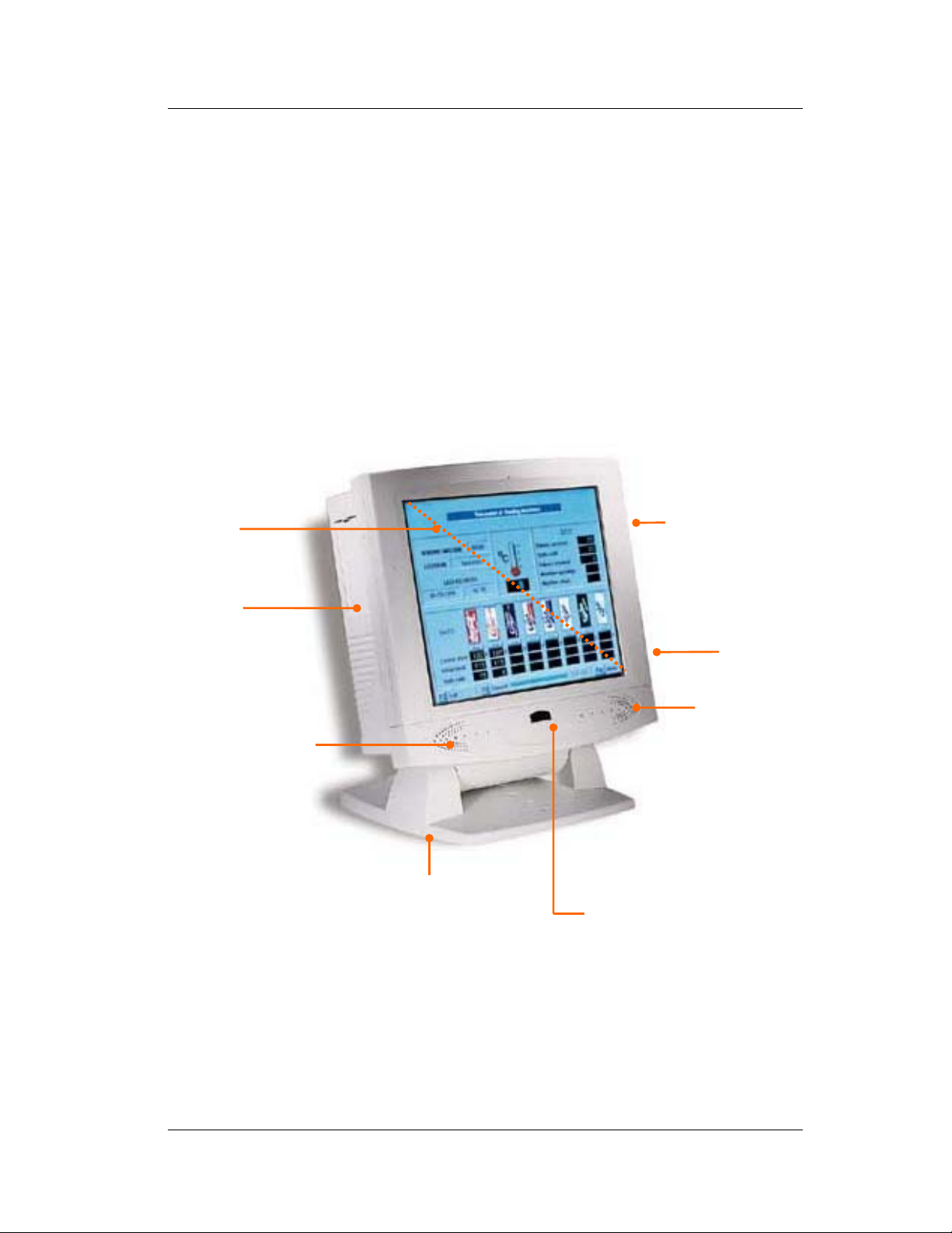
2.1.1.Front View
When the STH 15B Series is put upright on the desktop
with the provided pedestal, its front view appears as below.
The illustrations of the STH 15B Series may differ slightly .
15” LCD &
touch screen
Side door for
two PCI/ISA
expansion
outlet
Speaker
FDD drive &
CD-ROM drive
Fire-proof
resilient
plastic
Speaker
Big pedestal for
desktop standing
IrDA function
(reserved)
2-10
STH 15B Series
Page 23

User Manual version 4.11
2.1.2. Side Views
The left side of the panel PC appears as below:
2.1.3.
Side door for
two PCI/ISA
expansion
outlet
Floppy disk drive
CD-ROM
Big pedestal + Small base =
versatile stand A
Versatile stand design
for (30q to 47q) desktop
standing
STH 15B Series
2-11
Page 24

User Manual version 4.11
I/O Outlets
When you turn around the STH 15B system, you will find
the power switch and all the I/O ports are located at the rear
cover of the panel PC.
A B C D E F G H I
RCAS-VIDEO
COMPACT FLASH CARD
4 2 1
J K L M N O P Q R S T U
V
A. VR brightness B. TV-out S-terminal
(Optional SiS302)
D-IO
3
IEEE 1394
C. TV-out RCA Jack
(Optional SiS302)
D. Ethernet 1 E. Ethernet 2 F. 2-channel DIO
G. VGA port H. PS/2 Mouse I. PS/2 Keyboard
. Compact
J
.COM1
K
. COM 2
L
Flash slot
M. COM 3 N. COM 4 O. IEEE 1394 ports
P. USB ports Q. Speaker out R. MIC-in
. USB ports T. Print port
S
. Power switch
U
V. DC input
2-12
STH 15B Series
Page 25

User Manual version 4.11
2.2. System Setup for the First-time Use
To set up the STH 15B Series for the first-time use, you
should have the following items ready. The items are either
in the accessory box or available in any computer stores.
Power adapter & power cord
PS/2 or AT keyboard
PS/2 or serial mouse
2.2.1. Installation Procedures
1. Connect the female end of the adapter power cord to the
AC inlet located at the rear side of the panel PC.
2. Connect the 3-pin male end of the power cord to an
electrical outlet.
3. Connect a PS/2 keyboard or an AT keyboard to keyboard
port. If you are using an AT keyboard, you need an
adapter (AT to PS/2 KB) for this connection.
4. Connect the PS/2 mouse to the PS/2 mouse port. If you
are using a serial mouse, it can be connected to the COM
port.
5. Power on the panel PC by switching the power switch
located at the rear cover.
STH 15B Series
2-13
Page 26

User Manual version 4.11
2.2.2. Running the BIOS Setup
If you are a commercial user, the STH 15B Series should
have been properly set up and configured by your dealer. You
may still find it necessary to change the system configuration
information. In this case, you need to run the system’s BIOS
setup program.
Under the following conditions, the CMOS settings are to be
changed.
1. The system is starting for the first time.
2. The hardware devices attached to the STH 15B system
have been changed.
3. The CMOS memory has lost power and the configuration
information has been erased.
The BIOS setup program is stored in ROM, which can be
accessed by pressing <DEL> key on the keyboard
immediately when the system is powered on.
In order to retain the specified setup information when the
system power is turned off, the system setup information is
stored in a battery-backed CMOS RAM. The battery is to
ensure the settings will not be erased when the computer is
turned off or reset. When the computer is powered on again,
the system will read the settings stored in the CMOS RAM and
compare them to the equipment check conducted during the
power on self-test (POST). If any error or mismatch occurs,
an error message will be shown on the screen and the
computer will be prompted to run the setup program.
To change the BIOS setup, please refer to Chapter 7 for more
information.
2-14
STH 15B Series
Page 27

User Manual version 4.11
2.2.3. Operating System and Driver Installation
The STH 15B system is not equipped with an operating
system when delivered from the original manufacturer. If
you are a commercial user, the system is likely to have been
pre-installed proper operating system and software drivers
by your dealer or system integrator.
If the system is not pre-installed with any system OS and
drivers or you intend to install your preferred ones, there are
several ways to load OS and software into the system.
1. Via the CD-ROM
2. Via Ethernet: You can boot up the system via Ethernet
boot Rom and download system OS or software from the
network.
Recent releases of operating systems always include setup
programs that load automatically and guide you through the
installation. You can also refer to your OS user manual for
instructions on formatting or partitioning the hard disk drive
before any software installation.
The STH 15B system provides the following utility drivers
stored on the software CD:
Ethernet utilities
VGA utilities
Audio drivers
Touch screen drivers
STH 15B Series
2-15
Page 28

User Manual version 4.11
3. V
ERSATILE STANDING & MOUNTING OPTIONS
The STH 15B Series is designed for
universal standing and mounting to fit into
various environmental applications. This
chapter highlights the steps of different
mounting options with graphical illustrations.
Sections include
Upright Desktop standing
Angle free Desktop standing
Other stand options
Wall Mounting
Panel Mounting
3-16
STH 15B Series
Page 29

User Manual version 4.11
The STH 15B
system comes with a versatile stand
composing of one big pedestal and a small base. The
following diagrams show the major parts that make up the
STH 3047 stand.
F
IGURE
3-1: STH 3047
STH 15B Series
STAND A ASSEMBLY
3-17
Page 30

User Manual version 4.11
F
IGURE
3-2:
BIG PEDESTAL ASSEMBLY
3-18
STH 15B Series
Page 31

User Manual version 4.11
FIGURE 3-3: STH 15B SMALL BASE ASSEMBLY
STH 15B Series
3-19
Page 32

User Manual version 4.11
3.1. Upright Desktop Standing
Compact in its size, all-in-one in its design along with its
industrial-grade reliability, the STH 15B system standing
upright is the best replacement for a desktop computer.
When the STH 15B is to stand upright, only the big
pedestal kit is needed.
Before assembly
After assembly
3-20
FIGURE 3-4
F
STH 15B Series
IGURE
3-5
Page 33

User Manual version 4.11
3.2. 30 to 47o Desktop Standing
The sleek and stable pedestal assembled with the small base
enables the STH 15B system to endure the long-time
operation in any public sectors. By swiveling the two knobs
on the small base and pulling the base up and down, the
0
angle can be adjusted from 30 to 47
Before assembly
.
After assembly
STH 15B Series
F
IGURE
F
3-6
IGURE
3-7
3-21
Page 34

User Manual version 4.11
3.3. Other Stand Options
In addition to the standard stand, the STH 15B also
provides different stand options for special environmental
applications.
3.3.1.60 to 90o Desktop Standing
This stand is used when the STH 15B system is to stand
upright while the touch screen is frequently used. The big
pedestal assembled with a special small prop enables the
o
STH 15B to stand from 60 to 90
knobs on the back prop. The opening on the back prop can
act as a cable management cutout. All the cables connecting
to the I/O ports can come out from this cutout.
by swiveling the two
Cable management cutout.
F
IGURE
3-8
3-22
FIGURE 3-9
STH 15B Series
Page 35

User Manual version 4.11
3.4. Wall Mounting and Mobile Applications
The STH 15B system provides 2 sets of VESA holes,
75*75mm and 100*100mm on the rear side of the chassis.
System integrators can design their special wall mount
brackets per the two sets of VESA holes or obtain
market-available swing arms for wall mounting, table
mounting or mobile applications.
F
IGURE
3-13: STH 15B VESA
FIGURE 3-14 FIGURE 3-15
STH 15B Series
HOLES
3-23
Page 36

User Manual version 4.11
3.5. Panel Mounting
To use the STH 15B system in panel mount application, the
4 mounting holes on the upper side and the bottom side of
the rear cover need to be cut through first. Then, use the 4
optional mounting brackets or design your own mounting
brackets to mount the STH 15B system as shown on the
figure below:
Before mounting
After mounting
F
IGURE
F
IGURE
3-15
3-16
3-24
STH 15B Series
Page 37

User Manual version 4.11
4. I/O C
This chapter describes the STH 15B system
I/O ports and how to use the I/O interface to
connect to external devices.
ONNECTION
STH 15B Series
4-25
Page 38

User Manual version 4.11
The I/O interfaces located at the back side of the chassis are
used to connect external peripheral devices, such as a mouse,
a keyboard, a monitor, serial devices or parallel printer…etc.
Before any connection, make sure that the computer and the
peripheral devices are turned off.
S-VIDEO
COMPACT FLASH CARD
4
RCA
3
2 1
F
IGURE
D-IO
IEEE 1394
4-1
4.1. Parallel Port
The STH 15B Series can support the latest EPP and ECP
parallel port protocols. It can be used to connect to a wide
array of printers, ZIP drive, parallel scanner and any other
parallel devices. The printer interface on the STH 15B
Series is a 25-pin female D-SUB connector. To connect any
parallel device, follow the steps below:
1. Turn off the system and the parallel devices.
2. Plug in the male connector of the parallel device to the
25-pin female D-SUB connector and fasten the retaining
screws.
3. Turn on the system and the attached parallel devices.
4. Refer to the parallel device’s manual for instruction to
configure the operation environment to recognize the new
attached devices.
5. You may need to run the CMOS setup to change the
hardware device setup.
4-26
STH 15B Series
Page 39

User Manual version 4.11
4.2. COM Ports x 4
The STH 15B Series features with four onboard COM ports
located at the rear side of the chassis, ready to connect to a
wide range of serial devices. COM1, COM3 and COM4 are
RS-232 and COM2 is RS-232/485, selected via jumper
setting. Each COM port is with +5V/+12V power capabilities
on pin 9, providing easy accommodation to a broad range of
serial devices.
The COM port 5V/12 power is selected via jumper setting on
the IO–TR board. The IO-TR is the IO board docked to the
system motherboard to connect the onboard signal out to the
external I/O ports.
Please refer to the following for the 5V/12 power selection.
JP1 : COM1 & COM 2 Pin 9 5V / 12V Power selection
COM# Pin Function
1 - 2 Normal ----- -----
COM1
COM2
3 - 4 ----- +12V -----
5 - 6 ----- ----- +5V
7 - 8 Normal ----- -----
9 -10 ----- +12V -----
10 -11 ----- ----- +5V
STH 15B Series
4-27
Page 40

User Manual version 4.11
JP2 : COM3 Pin 9 5V / 12V Power selection
COM# Pin Function
1 - 2 Normal ----- -----
COM3
JP3 & JP4/5 : COM 2 is an RS-232/422/485 serial port. The specific
port type
is determined by JP3 and JP4/5.
JP3
RS-232 1-2 3-5 4-6 3-5 4-6
RS-485 3-4 1-3 2-4 1-3 2-4
RS-422 5-6 1-3 2-4 1-3 2-4
3 - 4 ----- +12V -----
5 - 6 ----- ----- +5V
JP4-1 JP4-2
1-3-5 2-4-6 1-3-5 2-4-6
Note : RS-422/485 pin assignment see Connectors and pin
define.
If a touch screen module is installed, for factory default
setting, its controller will occupy COM3.
COM1 to COM4 are all D-SUB 9-pin connectors. To connect to
any serial device; follow the procedures below;
1. Turn off the STH 15B system and the serial devices.
2. Attach the interface cable of the serial device to the 9-pin
D-SUB serial connector. Be sure to fasten the retaining
screws.
3. Turn on the computer and the attached serial devices.
4. Refer to the serial device’s manual for instruction to
configure the operation environment to recognize the new
attached devices.
4-28
STH 15B Series
Page 41

User Manual version 4.11
5. If the serial device needs specified IRQ or address, you
may need to run the CMOS setup to change the hardware
device setup.
If the COM2 is to be set to RS-485 for long distance
transmission, the related onboard jumpers have to be set
correctly first. Refer to section 6.2.1.2 for the RS-232/485
jumper settings and Appendix D for RS-485 programming.
STH 15B Series
4-29
Page 42

User Manual version 4.11
4.3. 100/10 Base-T Ethernet (RJ-45)
The STH 15B Series provides a 100/10 Base-T NE2000
compatible Ethernet (RJ-45) interface. For network
connection, follow the instructions below.
1. Turn of the STH 15B system and the Ethernet hubs.
2. Plug in one end of cable of a 100/10 Base-T hub to the
system’s RJ-45 phone jack. The pin assignment of the
RJ-45 is listed as follow;
1
234567
8
RJ-45
RJ-45 Connector Pin Assignment
Pin Description
1
2
3
6
others
Tx+ (data transmission positive)
Tx- (data transmission negative)
Rx+ (data reception positive)
Rx- (data reception negative)
No use
4-30
STH 15B Series
Page 43

User Manual version 4.11
4.4. VGA Interface
The STH 15B Series has a 15-pin analog RGB connector
located at the rear side of the chassis. It can support its own
LCD display and an expansion CRT or analog monitor at the
same time. However, because the LCD panel used in the 15”
system is of the resolution of 1024 x 768, in order to support
a CRT or analog monitor simultaneously, the monitor's VGA
resolution has to be set to 1024 x 768.
The connection to an analog monitor only requires the user to
plug-in the VGA D-SUB 15-pin connector to the RGB interface.
There is some application software that is to be executed in
800*600 resolution. When the software is running under
STH 15B 150, only part of the screen will show on the LCD
display. If the application has to run in full screen, you need
to update the system VGA drivers with an auto expansion
utility. However, due to resolution limitation, the text mode
will look slightly distorted.
4.5. PS/2 Keyboard Interface
The STH 15B Series provides a standard PS/2 keyboard
connector located at the rear panel. If the user would like to
use AT keyboard, then an adapter to connect the PS/2 KB to
AT KB is needed.
4.6. PS/2 Mouse Interface
The STH 15B system has one PS/2 mouse connector
located at the rear side. A simple plug-in will make the
connection.
STH 15B Series
4-31
Page 44

User Manual version 4.11
4.7. VR Brightness Control
The STH 15B system provides a VR control to adjust the
brightness of the LCD. The VR control is with a “+” shape
cutout on it. You will need a “+” shape screwdriver to adjust
it for display brightness control.
4.8. DIO (Digital Input & Output)
The STH 15B provides 2-channel DIO that can be used for
the system’s simple automation control needs. The digital I/O
can be configured to control the opening of a cash drawer or
to sense the warning signal of an uninterrupted power
system (UPS) or to do the store security control.
4-32
STH 15B Series
Page 45

User Manual version 4.11
4.9. TV-out Interface (Optional)
The TV-out interface supported by optional device with
SiS302 Chipset contains two types of connectors, one
S-terminal connector and the other RCA jack. The TV-out
interf ace is used when the TV or NTSC/PAL monitor is used as
the display monitor. Please note that either the TV or the LCD
can be used as the display at a given time; they can not
display images simultaneously.
Due to chipset limitation, when the TV monitor is used as the
display, the graphic mode is viewable while the text is hardly
legible.
To use the TV-out, the TV-out function in the BIOS setup
needs to be activated first. If your application is running
®
under Microsoft
Windows® environment, under Windows
Control Panel, you will see the following selections.
®
CRT
LCD
Both
TV
The default setting is “Both”. Cl ic k “ TV ” t o a ct iva te th e T V- out
function.
STH 15B Series
4-33
Page 46

User Manual version 4.11
4.10. Audio Interface (Line-in, MIC-in, SPK-out)
The audio interface contains three jacks, microphone-in,
line-in and speaker-out.
The microphone-in jack is used to record sound or voice by
connecting to an external microphone. The line-in jack is
used to input audio from an external audio device such as a
CD player, tape recorder or a radio. The speaker-out jack is
to output the audio to external devices such as speakers or
earphones. The audio device can be directly attached to the
jacks. Please note that the audio driver has to be installed
first before using any audio device.
4.11. 2.0 USB Ports
The STH 15B Series also provides four 2.0 USB ports to
connect to external USB devices. A simple plug-in of the USB
device interface cable to the USB port will make the
connection. Before using the USB devices, remember to
install the device driver first.
Notice: If OS is Windows XP, please download XP service pack 1.
Then system will recognize USB 2.0 devices.
4.12. IEEE 1394 ports
4 IEEE 1394 high-speed serial bus ports provide enhanced PC
connectivity for consumer electronics audio/video (A/V)
appliances, storage peripherals, other PCs, and portable
devices.
4.13. Compact Flash slot (Optional)
Provide one compact flash slot for removable Compact Flash
storage device.
4-34
STH 15B Series
Page 47

User Manual version 4.11
HARDWARE INSTALLATION AND UPGRADE
5.
This chapter overviews the installation of the
STH 15B ’s internal components and devices.
Sections include:
The exploded diagram
Touch screen & LCD assembly
Power module assembly
Installing the CPU
Installing the SDRAM
Installing the 3.5” HDD
Installing the slim FDD
Installing the compact CD/DVD-ROM
Expansion slots
STH 15B Series
5-35
Page 48

User Manual version 4.11
®
The STH 15B Series consists of a Pentium
4 embedded
mini board with an adequate CPU and relevant SDRAM on it.
The system control board and other internal devices such as
expansion card, HDD and power supply are already housed in
a plastic rear cover. The system’s performance depends on
the installed CPU and the capacity of the system memory and
hard disk drive. In some circumstances, you might intend to
upgrade or maintain the system. By removing the rear cover
and the metal covers, the internal components such as CPU,
SDRAM, HDD, internal FDD, CD-ROM and power supply can
be easily accessed for maintenance and upgrade.
5-36
STH 15B Series
Page 49

User Manual version 4.11
5.1. Recognizing the System Major Parts
The following diagram shows the system major parts that
make up the STH 15B Series .
FIGURE 5-1: STH 15B EXPLODED DIAGRAM
STH 15B Series
5-37
Page 50

User Manual version 4.11
5.2. Touch screen Module Assembly
The following diagram shows the steps to assemble the touch
screen to the front bezel. The assembly the STH 15B 150’s
speaker cover is in one piece with the front bezel.
The STH 15B is able to accommodate Elo analog resistive
touch or Intelli (SAW) touch screen. P
DIFFERENT TOUCH MODULE IS INSTALLED
METAL BRACKETS ARE NEEDED
TOUCH PANEL WITH THE OTHER WITHOUT CHANGING THE TOUCH SCREEN
METAL BRACKETS USED TO HOLD THE TOUCH PANEL TO THE FRONT BEZEL
. YOU CAN NOT REPLACE ONE TYPE OF
If no touch screen is installed, a resilient glass is to be
assembled instead.
LCD Module Assembly
The following diagram shows the way to assemble the LCD
module. The assembly of STH 15B LCD module.
LEASE NOTE THAT WHEN
,
DIFFERENT TOUCH SCREEN
.
FIGURE 5-4: STH 15B LCD MODULE ASSEMBLY
5-38
STH 15B Series
Page 51

User Manual version 4.11
F
IGURE
5-5: LCD
MODULE TO FRONT BEZEL
FIGURE 5-6: LCD MODULE TO MAIN SYSTEM
STH 15B Series
5-39
Page 52

User Manual version 4.11
5.3. Installing the CPU
The STH 15B Series system control board can adapt Intel£
®
Pentium£ 4 CPU. It can support Intel Pentium
CPU.
The system controller provides one 478-pin socket. The CPU
must come with a CPU fan to avoid overheating. The Pentium
4 CPU will request different kinds of CPU fans due the
difference on the CPUs’ mechanism. Wrong fans might lead to
overheating for the entire system. To install a CPU or upgrade
a new CPU, follow the instructions below.
1. If there is an existing CPU on the socket, remove the CPU
first by pulling the lever out a little and raising it, then
lifting out the existing CPU from the socket.
2. To insert the CPU into the socket, the notch on the corner
of the CPU (the corner with white dot) should point toward
the end of the socket lever. If the insertion of the CPU to
the socket is not easy, check whether the CPU pins
correspond with the holes on the socket.
4 Socket 478
3. After insert the CPU into the socket, pull the lever down to
make sure the CPU is in place.
4. The CPU cooling fan comes with a 3-pin power cable.
Connect the power cable to the 3-pin power connector on
the motherboard.
5. There are two small white clips on the CPU sockets. Make
sure the cooling CPU fan clips click into place.
CPU socket
3-pin CPU fan
power connector
FIGURE 5-8
5-40
STH 15B Series
Page 53

User Manual version 4.11
5.4. Installing the SDRAM Memory Module
The STH 15B Series system control board provides 2 x DDR
DIMM socket, able to support memory up to 2GB. To install
the memory module, follow the instructions below.
1. Find the DDR DIMM socket on the motherboard
2. There are two white eject levers at each end of the DIMM
socket. Push them outward until they separate from the
two vertical posts.
3. Holding the memory module with the notch on the upper
right corner, then insert the memory module into the
DIMM socket at 90q angle.
4. Push the two eject levers toward the vertical posts until
they click into place. The memory module is now
upright.
The system is able to auto detect the new memory size and
there is no need to change the system configuration after
installation.
Make sure that the memory module you are using can handle
the specified SDRAM MHz. Inadequate memory module will
make the computer unable to boot up.
STH 15B Series
5-41
Page 54

User Manual version 4.11
5.5. Installing the HDD
The STH 15B provides enough space to build in a 3.5” hard
disk drive in the system compartment.
If the user intends to attach a hard disk or remove the
existing device, the following steps shows the way to install
an internal hard disk drive.
1. Detach and remove the rear cover. Remove the system
metal cover located at the upper side of the chassis.
2. Invert the system compartment to make the upper side of
the chassis to be lower side.
3. Now, from your point of view, the 3.5" HDD module is
located at the left bottom side of the system compartment.
Detach the existing 3.5" HDD module from the system
chassis by removing the screw located at the left side of
the chassis.
4. Refer to figure 5-9. Remove the existing hard drive from
the HDD metal bracket (3).
5. Insert the HDD (1) and fix it to the metal bracket with 4
screws. Be sure to use the SHORT, round-head screws
provided by the HDD makers.
6. Insert the HDD module back to the chassis and fix it with
the screw located at the chassis side.
7. Connect the 4 pin power cable to the hard disk drive
8. Connect the 40-pin IDE cable (2) to hard disk drive. Make
sure the other end of the cable is already connected to the
motherboard secondary IDE connector.
5-42
STH 15B Series
Page 55

User Manual version 4.11
5.5.1.Internal FDD installation
Due to space limitation, when the STH 15B is installed with
an int ernal floppy disk drive, only a sl im type f loppy dis k d rive
can be used. The following steps show the ways to install an
internal FDD.
1. Detach and remove the rear cover. Remove the system
metal cover located at the upper side of the chassis.
2. Invert the system compartment to make the upper side of
the chassis to be lower side.
3. Now, from your point of view, the FDD module is located at
the right bottom side of the system compartment.
4. Take out the plastic FDD/CD-ROM cover at the right side of
the chassis first. Remove the two screws used to fix the
module to the chassis. Then, the FDD/CD-ROM module will
slide out of the chassis from the FDD/CD-ROM opening.
5. Refer to Figure 5-10. Attach one end of the 26-pin FDD flat
cable (3) to the slim floppy disk drive connector (2) first.
Match pin 1 of the floppy disk drive and pin 1 of the cable.
6. Place the floppy disk drive to the bracket (1). Fix it on the
bracket with the 4 screws.
There are two conditions.
A. No CD-ROM is to be accommodated to the system. Refer
to Figure 5-10 for reference.
1). Fix the FDD/CD-ROM board (4) to the FDD bracket (9).
2). Then, fix the FDD bracket with FDD/CD-ROM board to
the FDD/CD-ROM bracket (1).
3). Connect the other end of the 26-pin FDD cable (3) to
the 26-pin connector on the FDD/CD-ROM board (4).
STH 15B Series
5-43
Page 56

User Manual version 4.11
If a CD-ROM is to be accommodated to the system, no FDD
bracket (9) is needed for the installation. Refer to Section 5.9
for the CD-ROM installation procedure.
After the FDD or FDD/CD-ROM module is properly installed,
7. Insert the whole unit to the system compartment from the
CD-ROM/FDD opening. Fix it to the system chassis with
two screws.
8. Cut out the plastic slips on the FDD/CD-ROM plastic cover
to make openings for the insertion and ejection of the
floppy disk and CD diskette. Click the plastic cover into
place to the chassis.
9. Make sure the CD-ROM cable, 16-pin FDD cable, 4 pin
audio cable and 5V power cable are properly connected to all
the connectors on the FDD/CD-ROM board.
5-44
FIGURE 5-10: FDD INSTALLTION
STH 15B Series
Page 57

User Manual version 4.11
5.6. Installing the CD-ROM or DVD-ROM
The CD-ROM or DVD-ROM drive used in the STH 15B Series
is not the common 5.25” drive seen in computer stores.
Rather, it is a slim type drive widely used in notebook
computers. The following steps show the ways to install an
internal CD-ROM or DVD-ROM.
1. Detach and remove the rear cover. Remove the system
metal cover located at the upper side of the chassis.
2. Invert the system compartment to make the upper side of
the chassis to be lower side.
3. Now, from your point of view, the FDD/CD-ROM module is
located at the right bottom side of the system
compartment.
4. Take out the plastic FDD/CD-ROM cover at the right side of
the chassis first. Remove the two screws used to fix the
module to the chassis. Then, the FDD/CD-ROM module will
slide out of the chassis from the FDD/CD-ROM opening.
5. Refer to figure 5-12. If a floppy drive is to be installed, too,
fix the FDD (2) with cable (3) to the FDD/CD-ROM metal
bracket (1) first.
6. Attach the FDD/CD-ROM board (6) to the slim CD-ROM
drive (4). P
WITH
2 PLASTIC WASHERS (7).
LEASE NOTE THAT THE 2 SCREWS NEED TO BE INCASED
7. Fix the small CD-ROM bracket (5) to the CD-ROM drive.
This small bracket is to prevent the CD-ROM unit from
moving when installed to the FDD/CD-ROM (1).
8. Place the CD-ROM unit on the FDD/CD-ROM bracket. Fix
the unit on the bracket with the 2 screws.
9. Insert the whole unit to the system compartment from the
CD-ROM/FDD opening.
10. Cut out the plastic slips on the FDD/CD-ROM plastic
cover to make openings for the insertion and ejection of
the floppy disk and CD diskette. Click the plastic cover into
place to the chassis.
STH 15B Series
5-45
Page 58

User Manual version 4.11
11. Connect the 44 pin-IDE cable (8) to the 44 pin IDE
connector on the FDD/CD-ROM board. Make sure the
other end of the cable is connector the motherboard
primary IDE connector.
12. Make sure the 26 pin FDD flat cable, 16 pin FDD cable, 4
pin audio cable and 5V power cable is properly connected
to all the connectors on the FDD/CD-ROM board.
F
IGURE
5-11: FDD/CD-ROM
BOARD
5-46
F
IGURE
5-12: FDD/CD-ROM
INSTALLATION
STH 15B Series
Page 59

User Manual version 4.11
Expansion Slots
The STH 15B Series provides PCI/ISA expansion slots for
system expansion. Via the specially designed riser card, the
system can accommodate either two PCI or one ISA and one
PCI expansion cards.
Due to the internal space limitation, there is card size
limitation.
If PCI expansion cards are used, the card size cannot exceed
the following.
st
PCI card: 290*120 mm (L*W)
1
nd
PCI card: 160*120 mm (L*W)
2
1. Detach and remove the rear cover. Remove the system
metal cover located at the upper side of the chassis.
2. Invert the system compartment to make the upper side of
the chassis to be lower side.
3. Now, from your point of view, the riser
card is located at the left bottom side of
the system compartment.
4. Unscrew the 2 metal slips located inside
the expansion outlet.
5. Plug the expansion cards into the PCI slot on the riser card
and fix the expansion card by screwing it to the metal
expansion frame. All the connectors of the expansion card
will come out from the expansion outlet on the left side of
the chassis for further cable connection.
STH 15B Series
5-47
Page 60

User Manual version 4.11
6. S
YSTEM CONTROL BOARD
The system controller used in the STH 15B
system is a Pentium
®
4 multimedia embedded
little board, PC 761. This chapter provides detail
introduction of the system engine.
6-48
STH 15B Series
Page 61

User Manual version 4.11
6.1. Introduction
This section provides background information and detail
specification on the STH 15B Series system engine, PC
761. Sections include:
General Information
Features
Specification
Board placement & Dimension
General Information
The motherboard is an Intel Pentium® 4 (Socket 478) multimedia
miniboard. Compact in size and with its highly integrated
multimedia and networking functions, this miniboard is the most
powerful PC engine to build any small footprint all-in-one PC
system for integration into any space-constricted embedded
applications. Highly integrated, it is perfect for running Intel£
Pentium 4 (533/400MHz) and Tualatin CPU. Onboard features
include super I/Os, XGA, LCD interface, IrDA, 10/100 Base-T
Ethernet and audio functions. The full PC functionality
coupled with its multi-I/Os stand ready to accommodate a
wide range of PC peripherals. Special industrial feature not
commonly seen in commercial systems such as watchdog
timer makes this miniboard the best choice for the operation in
any hostile environments.
Fully configurable and with its modular design, it is an ideal
platform for any consumer computing applications where space
is a premium.
STH 15B Series
6-49
Page 62

User Manual version 4.11
6.2. Board Placement & Dimension
The mainboard dimensions and layout are shown below;
6-50
STH 15B Series
Page 63

User Manual version 4.11
6.3. Main board Jumpers & Jumper Setting
The table below lists the function of each jumper. The related
jumper settings are shown in the coming sections.
On Main Board:
Description
JP1 Reset switch
JRTC1 RTC enable & clear CMOS
PWR DC-DC 34 pin 2.54mm power connector
IDE1 1st channel 3.5” IDE connector
IDE2 2nd channel 3.5” IDE connector
LINKA LINK A board connector
LINKB LINK B board connector
LINKC LINK C board connector
Slot-PCI PSD-RISER-PCI board connector
Slot-AMR PSD-RISER-PCI board connector
JP3 SIR & LED connector
FAN1 CPU FAN connector
FAN2 System FAN connector
USB1 USB connector to LINK C board USB1 pin head
J1 Video in from 302LV board
JLINC +5V/+12V power connector
CN1 Inverter connector
CN2 +5V/+12V power connector
LCD1 LCD connector
LCF1 To LINK B board (IDE1) connector
STH 15B Series
6-51
Page 64

User Manual version 4.11
6.3.1.CMOS Clear Setting (JRTC1)
Before setting “CMOS Clear”, remember to turn off the power
supply to avoid damaging the computer board. After the
setting, before turning on the power supply, set the jumper
back to “RTC enable”.
1-2
2-3
Clear CMOS
RTC enable
Default
6.3.2.PWR: 34 pin power connector
Pin No Signal Pin No Signal
1 PSON- 2 PWOK
3 VCC3 4 VCC3
5 VCC3 6 VCC3
7 VCC3 8 GND
9 -12V 10 GND
11 SB5V 12 GND
6-52
13 SB5V 14 VCC5
15 VCC5 16 VCC5
17 VCC5 18 VCC5
19 GND 20 GND
21 GND 22 GND
23 GND 24 GND
25 GND 26 GND
27 GND 28 +12V
29 +12V 30 +12V
31 +12V 32 +12V
33 +12V 34 +12V
STH 15B Series
Page 65

User Manual version 4.11
6.3.3.
IDE1 : 1st channel HDD connector
Pin No Signal Pin No Signal
1 IDE Reset# 2 GND
3 Data 07-A 4 Data 08-A
5 Data 06-A 6 Data 09-A
7 Data 05-A 8 Data 10-A
9 Data 04-A 10 Data 11-A
11 Data 03-A 12 Data 12-A
13 Data 02-A 14 Data 13-A
15 Data 01-A 16 Data 14-A
17 Data 00-A 18 Data 15-A
19 GND 20 NC
21 IDEDRQ-A 22 GND
23 IOW#-A 24 GND
25 IOR#-A 26 GND
27 ICHRDY#-A 28 GND
29 DACK-A 30 GND
31 IDEIRQ-A 32 NC
33 A1-A 34 NC
35 A0-A 36 A2-A
37 IDECS0-A 38 IDECS1-A
39 HDD LED-A 40 GND
240
STH 15B Series
6-53
Page 66

User Manual version 4.11
6.3.4.
IDE2 : 2nd channel HDD connector
Pin No Signal Pin No Signal
1 IDE Reset# 2 GND
3 Data 07-B 4 Data 08-B
5 Data 06-B 6 Data 09-B
7 Data 05-B 8 Data 10-B
9 Data 04-B 10 Data 11-B
11 Data 03-B 12 Data 12-B
13 Data 02-B 14 Data 13-B
15 Data 01-B 16 Data 14-B
17 Data 00-B 18 Data 15-B
19 GND 20 NC
21 IDEDRQ-B 22 GND
23 IOW#-B 24 GND
25 IOR#-B 26 GND
27 ICHRDY#-B 28 GND
29 DACK-B 30 GND
31 IDEIRQ-B 32 NC
33 A1-B 34 NC
35 A0-B 36 A2-B
37 IDECS0-B 38 IDECS1-B
39 HDD LED-B 40 GND
41 +5V 42 +5V
43 GND 44 NC
340
6-54
STH 15B Series
Page 67

6.3.5.J1 : Video In connector
Pin No Signal
1 TVDACR
2 TVDACG
User Manual version 4.11
3 TVDACB
1 4
4 GND
6.3.6.JLINC : Power connector
Pin No Signal
1 VCC5
2 GND
3 GND
1 4
4 +12V
6.3.7.CN1 : Inverter connect
Pin No Signal
1 BKADJ
2 GND
1 4
3 Backlight on/off
4 +12V
6.3.8.CN2 : Power connector
Pin No Signal Pin No Signal
1 VCC5 2 VCC5
3 GND 4 VCC5
5 GND 6 GND
7 +12V 8 GND
9 +12V 10 +12V
STH 15B Series
6-55
Page 68

User Manual version 4.11
6.3.9.JP3 : SIR&LED connector
Pin No Signal Pin No Signal
1 +5V 2 SB5V
3 HDD LED 4 LAN LED
5 ACPI LED 6 GND
7 SPK-LO 8 SPK-RO
9 SPK-LN 10 SPK-RN
11 GND 12 GND
13 IRRX 14 IRTX
6.3.10. USB1 : USB connector
Pin No Signal Pin No Signal
1 GND 2 GND
3 GND 4 GND
5 +Data_4 6 +Data_3
7 -Data_4 8 -Data_3
9 VCC_USB 10 VCC_USB
6.3.11. FAN1 : System FAN connector
PIN No Signal
1 GND
1
2 +12V
3
3 FAN IO_1
6-56
STH 15B Series
Page 69

User Manual version 4.11
6.3.12.
FAN2 : CPU FAN connector
PIN No Signal
1 GND
2 +12V
1
3
3 FAN IO_2
6.3.13. LCF 1 : CF connector
Pin No Signal Pin No Signal
1 IDE Reset# 2 GND
3 Data 07-A 4 Data 08-A
5 Data 06-A 6 Data 09-A
7 Data 05-A 8 Data 10-A
9 Data 04-A 10 Data 11-A
11 Data 03-A 12 Data 12-A
13 Data 02-A 14 Data 13-A
15 Data 01-A 16 Data 14-A
17 Data 00-A 18 Data 15-A
19 GND 20 NC
21 IDEDRQ-A 22 GND
23 IOW#-A 24 GND
25 IOR#-A 26 GND
27 ICHRDY#-A 28 GND
29 DACK-A 30 GND
31 IDEIRQ-A 32 NC
33 A1-A 34 NC
35 A0-A 36 A2-A
37 IDECS0-A 38 IDECS1-A
39 HDD LED-A 40 GND
41 +5V 42 +5V
43 GND 44 NC
STH 15B Series
6-57
Page 70

User Manual version 4.11
6.3.14. LCD : LCD / SiS302LV connector
1. Direct driver maximum 24bits TTL/CMOS TFT LCD
2. Add scaling board can driver 48bits TTL/CMOS TFT LCD
( Heisei scaling --- SPD1015E maximum resolution is
1024 X 768 true colors )
3. Add SiS302LV board can diver LVDS LCD and support TV
function simultaneously
**For over and with 1280 x 1024 resolution LVDS LCD
panel have to add SiS302LV board and select resolution
in BIOS selection.
Pin No Signal Pin No Signal Pin No Signal Pin No Signal
1 +5V 2 +5V 27 R2 28 R3
3 GND 4 GND 29 R4 30 R5
5 +3.3V 6 +3.3V 31 R6 32 R7
7 VBCAD 8 VBCTL0 33 GND 34 GND
9 B0 10 B1 35 SHFCLK 36 FLM
11 B2 12 B3 37 DE 38 LP
13 B4 14 B5 39 GND 40 GND
15 B6 16 B7 41 VBCTL1 42 VBCLK
17 G0 18 G1 43 GND 44 VA_HS
19 G2 20 G3 45 VA_VS 46 VBHCLK
21 G4 22 G5 47 VADE 48 PCIRST#
23 G6 24 G7 49 VGACLK 50 INTA#
25 R0 26 R1
2 50
1 49
6-58
STH 15B Series
Page 71

User Manual version 4.11
6.4. Riser-PCI board Jumpers
The table below lists the function of each jumper.
Description
CN1 Add grounding(power)
FDD FDD connector
Touch Touch screen connector (Link to LINK B board
enable rear COM 3 function)
PCI1/2 PCI slot
6.4.1.FDD : FDD connector
Pin No Signal Pin No Signal
1 READWC# 2 INDEX#
3 MOTOA# 4 DRVA#
5 DIR# 6 WTPROT#
7 TRK0# 8 WGATE#
9 WTDATA# 10 STEP#
11 RDATA# 12 HEAD#
13 DSKCHG# 14 GND
15 GND 16 GND
STH 15B Series
6-59
Page 72

User Manual version 4.11
6.4.2.TOUCH : TOUCH connector
Pin No Signal Pin No Signal
1 DCDC 2 DSRC
3 SINC 4 RTSC
5 SOUTC 6 CTSC
7 DTRC 8 RIC
9 GND 10 NC
6.4.3.CN1 : Grounding connector
PIN No Signal
1 +12V
2 GND
3 GND
4 VCC5 ( +5V )
1 4
6-60
STH 15B Series
Page 73

User Manual version 4.11
6.4.4.PCI Slot
Pin No Signal Pin No Signal Pin No Signal Pin No Signal
B01 -12V A01 TRST- B32 AD17 A32 AD16
B02 TCK A02 +12V B33 C/BE#2 A33 3.3V
B03 GND A03 TMS B34 GND A34 FRAME#
B04 NC A04 TDI B35 IRDY# A35 GND
B05 +5V A05 +5V B36 3.3V A36 TRDY#
B06 +5V A06
B07
B08
B09 PRSNT-1 A09 NC B40 PERR# A40 Reserved
B10 NC A10 +5V B41 3.3V A41 Reserved
B11 PRSNT-2 A11 NC B42 SERR# A42 GND
B12 GND A12 GND B43 3.3V A43 PAR
B13 GND A13 GND B44 C/BE#1 A44 AD15
B14 NC A14 VCC3 Dual B45 AD14 A45 3.3V
B15 GND A15 PCIRST# B46 GND A46 AD13
B16 PCICLK A16 +5V B47 AD12 A47 AD11
B17 GND A17
B18
B19 +5V A19 PME- B50 A50
B20 AD31 A20 AD30 B51 A51
B21 AD29 A21 3.3V B52 AD8 A52 C/BE#0
INT-B
INT-D
REQ#
Ϫ
Ϫ
Ϫ
A07
A08 +5V B39 LOCK# A39 3.3V
A18 GND B49 GND A49 AD9
INT-A
INT-C
GNT#
Ϫ
Ϫ
Ϫ
B37 DEVSEL# A37 GND
B38 GND A38 STOP#
B48 AD10 A48 GND
B22 GND A22 AD28 B53 AD7 A53 3.3V
B23 AD27 A23 AD26 B54 3.3V A54 AD6
B24 AD25 A24 GND B55 AD5 A55 AD4
B25 3.3V A25 AD24 B56 AD3 A56 GND
B26 C/BE#3 A26
B27 AD23 A27 3.3V B58 AD1 A58 AD0
B28 GND A28 AD22 B59 +5V A59 3.3V
B29 AD21 A29 AD20 B60 ACK#64 A60 REQ64#
B30 AD19 A30 GND B61 +5V A61 +5V
B31 3.3V A31 AD18 B62 +5V A62 +5V
IDSEL
Ϫ
B57 GND A57 AD2
STH 15B Series
6-61
Page 74

User Manual version 4.11
PCI Routing address:
Ϫ
PCI1 Define System
INT-A INT-D
INT-B INT-A
INT-C INT-B
INT-D INT-C
GNT# GNT 2#
REQ# REQ 2#
IDSEL AD29
PCI2 Define System
INT-A INT-C
INT-B INT-D
INT-C INT-A
INT-D INT-B
GNT# GNT 1#
REQ# REQ 1#
IDSEL AD30
6-62
STH 15B Series
Page 75

User Manual version 4.11
6.5. LINK A board Jumpers
On LINK A board without any Jumper. The connector
definition please back to chapter 4.
STH 15B Series
6-63
Page 76

User Manual version 4.11
6.6. LINK B board Jumpers & setting
The table below lists the function of each jumper & setting.
Description
Touch Touch screen connector (Link to LINK B board
enable rear COM 3 function)
IDE1 Link to System board LCF1 connector for enable
rear side compact flash function
PCI1/2 PCI slot
J4 CD Audio connector
6.6.1.TOUCH : TOUCH connector
Pin No Signal Pin No Signal
1 DCDC 2 DSRC
3 SINC 4 RTSC
5 SOUTC 6 CTSC
7 DTRC 8 RIC
9 GND 10 NC
6-64
STH 15B Series
Page 77

User Manual version 4.11
6.6.2.IDE1 : 1st channel HDD connector
Link to system board LCF1 connector for rear side compact
flash disk function.
Pin No Signal Pin No Signal
1 IDE Reset# 2 GND
3 Data 07-A 4 Data 08-A
5 Data 06-A 6 Data 09-A
7 Data 05-A 8 Data 10-A
9 Data 04-A 10 Data 11-A
11 Data 03-A 12 Data 12-A
13 Data 02-A 14 Data 13-A
15 Data 01-A 16 Data 14-A
17 Data 00-A 18 Data 15-A
19 GND 20 NC
21 IDEDRQ-A 22 GND
23 IOW#-A 24 GND
25 IOR#-A 26 GND
27 ICHRDY#-A 28 GND
29 DACK-A 30 GND
31 IDEIRQ-A 32 NC
33 A1-A 34 NC
35 A0-A 36 A2-A
37 IDECS0-A 38 IDECS1-A
39 HDD LED-A 40 GND
STH 15B Series
6-65
Page 78

User Manual version 4.11
CF Header definition
Pin No Signal Pin No Signal Pin No Signal Pin No Signal
1 GND1 2 D03 27 D11 28 D12
3 D04 4 D05 29 D13 30 D14
5 D06 6 D07 31 D15 32 CS1#
7 CS0# 8 FGND 33 FGND 34 IORD#
9 FGND 10 FGND 35 IOWR# 36 +5V
11 FGND 12 FGND 37 INTRQ 38 +5V
13 +5V 14 FGND 39 +5VF 40 NC
15 FGND 16 FGND 41 RESET
17 FGND 18 A02 43 NC 44 DACK#
19 A01 20 A00 45 DASP# 46 PDIAG#
21 D00 22 D01 47 DA8 48 DA9
23 D02 24 IOCS16
#
25 FGND 26 FGND
49 DA10 50 FGND
6.6.3.J4 : CD audio in connector
Pin No Signal
1 CD_L
2 GND
4
1
3 GND
42 IORDY
#
6-66
4 CD_R
STH 15B Series
Page 79

User Manual version 4.11
6.7. LINK C board Jumpers & setting
The table below lists the function of each jumper & setting.
Description
CN2 Add grounding (power)
JP1 COM1 & COM 2 Pin#9 5V/12V Power selection
JP2 COM3 Pin#9 5V/12V Power selection
JP3 RS-232/422/482 selection
JP4-1 RS-232/422/482 selection
JP4-2 RS-232/422/482 selection
6.7.1.CN2 : Grounding connector
Pin No Signal
1 +12V
2 GND
4
1
3 GND
4 VCC5 (+5V)
STH 15B Series
6-67
Page 80

User Manual version 4.11
6.7.2.JP1 COM1/COM2 Pin9 Power selection
COM 1 COM 2
Normal 12V 5V Normal 12V 5V
26
26
26
812
812
812
1
5
1
5
1
5
7
11 7
11 7
11
1-2 3-4 5-6 7-8 9-10 11-12
6.7.3.JP2 COM3 Pin9 Power selection
COM 3
Normal 12V 5V
1-2 3-4 5-6
6.7.4.JP3 & JP4-1/2 COM2 RS-232/422/482 selection
JP3 JP4-1 JP4-2
RS-232
RS-485
RS-422
Note : RS-422/485 pin assignment see Connectors and pin define.
6-68
STH 15B Series
Page 81

User Manual version 4.11
7. AWARD BIOS S
The chapter describes how to set up BIOS
configuration.
ETUP
STH 15B Series
7-69
Page 82

User Manual version 4.11
7.1. Award BIOS
The Award BIOS ROM builds in a setup program, which allows
the users to modify the basic system configuration such as
the current date and time or the type of peripheral devices
attached to the computer.
Under the following conditions, the CMOS settings are to be
changed;
4. The system is starting for the first time
5. The hardware devices attached to the systems have been
changed
6. The CMOS memory has lost power and the configuration
information has been erased.
The BIOS setup program is stored in ROM, which can be
accessed by pressing <DEL> key on the keyboard
immediately when the system is powered on.
In order to retain the specified setup information when the
system power is turned off, the system setup information is
stored in a battery-backed CMOS RAM. The battery is to
ensure the settings will not be erased when the computer is
turned off or reset. When the computer is powered on again,
the system will read the settings stored in the CMOS RAM and
compare them to the equipment check conducted during the
power on self test (POST). If any error or mismatch occurs,
an error message will be shown on the screen and the
computer will be prompted to run the setup program.
7-70
STH 15B Series
Page 83

7.2. Control Key Definition
Up arrow Move to previous item
User Manual version 4.11
Down
arrow
Left arrow Move to the item in the left hand
Right
arrow
ESC key Main Menu - Quit and not save changes into
PgUp key Increase the numeric value or make
PgDn key Decrease the numeric value or make
F1 key General help, only for Status Page Setup
F2 key Item Help
F3 key Reserved
Move to next item
Move to the item in the right hand
CMOS
Status Page Setup Menu and Option Page
Setup Menu - Exit current page and return
to Main Menu
changes
changes
Menu and Option Page Setup Menu
F4 key Reserved
F5 key Restore the previous CMOS value from
CMOS, only for Option Page Setup Menu
F6 key Load the Fail safe default CMOS value from
BIOS default table, only for Option Page
Setup Menu
F7 key Load the Optimize default
F8 key Reserved
F9 key Reserved
F10 key Save all the CMOS changes, only for Main
Menu
STH 15B Series
7-71
Page 84

User Manual version 4.11
7.3. Getting Help
7.3.1.Main Menu
The on-line description of the highlighted setup function is
displayed at the bottom of the screen.
Press <F1> to pop up a small help window that describes the
appropriate keys to use and the possible selections for the
highlighted item. To exit the Help Window, press <ESC>.
7.4. AWARD BIOS Setup
7.4.1.AWARD BIOS Setup Main Menu
Power on the computer and press <DEL> immediately to run
the AWARD BIOS setup. The setup main menu will appear on
the screen;
Use the arrow keys to move among the items and press
<Enter> to enter the sub-menu.
7-72
STH 15B Series
Page 85

TANDARD CMOS SETUP: This setup page includes all the
S
items in standard compatible BIOS.
User Manual version 4.11
A
DVANCED
BIOS F
EATURES
: This setup page includes all
the items of Award special enhanced features.
A
DVANCED CHIPSET FEATURES
: This setup page includes
all the items of chipset special features.
NTEGRATED PERIPHERALS: This setup page includes all
I
onboard peripherals.
P
OWERMANAGEMENT SETUP
: This setup page includes all
the items of Green function features.
P
NP/PCI CONFIGURATION: This setup page includes all
the configurations of PCI & PnP ISA resources.
PC H
EALTH STATUS: This setup page auto detects the
temperature, voltage and fan speed.
F
REQUENCY/VOLTAGE CONTROL
: This setup page includes
the CPU/SDRAM/PCI frequency setting
L
OAD FAIL-SAFE DEFAULTS: BIOS Defaults indicates the
most appropriate value of the system parameters that
the system would be in safe configuration.
L
OAD OPTIMIZED DEFAULTS
: Setup Defaults indicates the
value of the system parameters that the system would
be in the best performance configuration.
ET PASSWORD: Change, set, or disable password. It
S
allows you to limit access to the system and Setup, or
just to Setup.
S
AVE & EXIT SETUP: Save CMOS value settings to CMOS
and exit setup.
XIT WITHOUT SAVING: Abandon all CMOS value changes
E
and exit setup.
STH 15B Series
7-73
Page 86

User Manual version 4.11
7.5. AWARD BIOS Setup Main Menu
Power on the computer and press <DEL> immediately to run
the AWARD BIOS setup. The setup main menu will appear on
the screen;
Use the arrow keys to move among the items and press
<Enter> to enter the sub-menu.
7-74
STH 15B Series
Page 87

TANDARD CMOS SETUP: This setup page includes all the
S
items in standard compatible BIOS.
User Manual version 4.11
A
DVANCED
BIOS F
EATURES
: This setup page includes all
the items of Award special enhanced features.
A
DVANCED CHIPSET FEATURES
: This setup page includes
all the items of chipset special features.
NTEGRATED PERIPHERALS: This setup page includes all
I
onboard peripherals.
P
OWERMANAGEMENT SETUP
: This setup page includes all
the items of Green function features.
P
NP/PCI CONFIGURATION: This setup page includes all
the configurations of PCI & PnP ISA resources.
PC H
EALTH STATUS: This setup page auto detects the
temperature, voltage and fan speed.
F
REQUENCY/VOLTAGE CONTROL
: This setup page includes
the CPU/SDRAM/PCI frequency setting
L
OAD FAIL-SAFE DEFAULTS: BIOS Defaults indicates the
most appropriate value of the system parameters that
the system would be in safe configuration.
L
OAD OPTIMIZED DEFAULTS
: Setup Defaults indicates the
value of the system parameters that the system would
be in the best performance configuration.
ET PASSWORD: Change, set, or disable password. It
S
allows you to limit access to the system and Setup, or
just to Setup.
S
AVE & EXIT SETUP: Save CMOS value settings to CMOS
and exit setup.
XIT WITHOUT SAVING: Abandon all CMOS value changes
E
and exit setup.
STH 15B Series
7-75
Page 88

User Manual version 4.11
7.5.1.Standard CMOS Features
If the STANDARD CMOS FEATURE is selected from the
main menu, the screen below will appear. This menu allows
the users to configure the system components such as date,
time, hard disk drive, floppy disk drive and display type. The
system BIOS will automatically detect the memory size;
therefore no setting is needed.
ATE
D
The date format is <day>, <month> <date> <year>.
day The day, from Sun to Sat, determined by the
BIOS and is display-only
month The month, Jan. through Dec.
date The date, from 1 to 31 (or the maximum
allowed in the month)
year The year, from 1994 through 2079
IME
T
The times format in <hour> <minute> <second>. The time
is calculated base on the 24-hour military-time clock. For
example, 1 p.m. is 13:00:00.
7-76
P
RIMARY
HDDS/S
ECONDARY
HDD
S
STH 15B Series
Page 89

User Manual version 4.11
The category identifies the types of hard disk from drive C to
F that has been installed in the computer. There are two types:
auto type, and user definable type. User type is
user-definable; Auto type which will automatically detect
HDD type.
Note that the specifications of your drive must match with the
drive table. The hard disk will not work properly if you enter
improper information for this category.
If you select User Type, related information will be asked to
enter to the following items. Enter the information directly
from the keyboard and press <Enter>. Such information
should be provided in the documentation form your hard disk
vendor or the system manufacturer.
CYLS. Number of cylinders
HEADS number of heads
PRECOMP write precomp
LANDZONE Landing zone
SECTORS number of sectors
If a hard disk has not been installed select NONE and press
<Enter>.
STH 15B Series
7-77
Page 90

User Manual version 4.11
RIVE A TYPE /DRIVE B TYPE
D
The category identifies the types of floppy disk drive A or
drive B that has been installed in the computer.
None No floppy drive installed
360K, 5.25" 5.25 inch PC-type standard drive; 360K byte
1.2M, 5.25" 5.25 inch AT-type high-density drive; 1.2M byte
(3.5 inch when 3 Mode is Enabled).
720K, 3.5" 3.5 inch double-sided drive; 720K byte
1.44M, 3.5" 3.5 inch double-sided drive; 1.44M byte
2.88M, 3.5" 3.5 inch double-sided drive; 2.88M byte
IDEO
V
The category selects the default video device
Options: EGA/VGA/CGA40/CGA80/Mono
ALT ON
H
The category determines whether the computer will stop if an
error is detected during power up.
NO Errors The system boot will not stop for any
error that may be detected
All Errors Whenever the BIOS detects a
non-fatal error the system will be
stopped and you will be prompted
All, But Keyboard The system boot will not stop for a
keyboard error; it will stop for all
other errors
All, But Diskette The system boot will not stop for a
disk error; it will stop for all other
errors
All, But Disk/Key The system boot will not stop for a
keyboard or disk error; it will stop for
all other errors
7-78
STH 15B Series
Page 91

User Manual version 4.11
7.5.2.Advanced BIOS Features
If the ADVANCED BIOS FEATURES option is selected from
the main menu, the screen below will appear. The following
sample screen consists of the default values for STH 15B.
STH 15B Series
7-79
Page 92

User Manual version 4.11
7.5.3.Advanced Chipset Features
If the ADVAMCED CHIPSET FEATURES option is selected
from the main menu, the screen below will appear. The
following sample screen consists of the default values for
STH 15B.
7-80
STH 15B Series
Page 93

User Manual version 4.11
7.5.4.Integrated Peripherals
If the INTEGRATED PERIPHERALS option is selected from
the main menu, the screen below will appear. The following
sample screen consists of the default values for STH 15B.
SIS OnChip IDE Device
STH 15B Series
7-81
Page 94

User Manual version 4.11
SIS OnChip PCI Device
LCD Panel ID Selection
7-82
STH 15B Series
Page 95

Onboard SuperIO Device
User Manual version 4.11
STH 1B Series
7-83
Page 96

User Manual version 4.11
7.5.5.Power Management Setup
If the POWER MANAGEMENT SETUP option is selected
from the main menu, the screen below will appear. The
following sample screen consists of the default values for
STH 15B.
PM Wake up Events
7-84
STH 15B Series
Page 97

User Manual version 4.11
7.5.6.PnP/PCI Configuration
If the PNP/PCI CONFIGURATION option is selected from
the main menu, the screen below will appear. The following
sample screen consists of the default values for STH 15B.
7.5.7.PC Health Status
The PC HEALTH STATUS auto detects the system’s
temperature, voltage and fan speed.
STH 15B Series
7-85
Page 98

User Manual version 4.11
CPU Warning Temperature:
Shutdown Temperature
7-86
STH 15B Series
Page 99

User Manual version 4.11
7.5.8.Frequency Voltage Control
This setup page is for the CPU, SDRAM and PCI frequency
setting.
7.5.9.Load Fail-Safe Defaults
The default values of the LOAD FAIL-SAFE DEFAULTS
indicates the most appropriate value of the system
parameters that the system would be in safe configuration.
STH 15B Series
7-87
Page 100

User Manual version 4.11
7.5.10. Load Optimized Defaults
The default values of the LOAD OPTIMIZED DEFAULTS
indicates the most appropriate value of the system
parameters that the system would be in best performance
configuration.
7-88
STH 15B Series
 Loading...