

Page 1

Panel PCs
STE 1xGTx Series
NEMA 4 Sealed Touchscreen Panel
PC Systems with VGA, Ethernet, PCI
Expansion, AC or DC Power Input,
and USB
®
No part of this manual may be reproduced without permission
CyberResearch®,Inc.
25 Business Park Dr., Branford, CT 06405 USA
203-643-5000 (9
USER’S MANUAL
VER. 2.0C• Feb-11
www.cyberresearch.com
A.M. to 5 P.M. EST) FAX: 203-643-5001
Page 2

Page 3

CyberResearch® Panel PCs
STE 1xGTx Series
©Copyright 2011
All Rights Reserved.
February 19, 2011
The information in this document is subject to change without prior notice in order
to improve reliability, design, and function and does not represent a commitment
on the part of CyberResearch, Inc.
In no event will CyberResearch, Inc. be liable for direct, indirect, special,
incidental, or consequential damages arising out of the use of or inability to use
the product or documentation, even if advised of the possibility of such damages.
This document contains proprietary information protected by copyright. All rights
are reserved. No part of this manual may be reproduced by any mechanical,
electronic, or other means in any form without prior written permission of
CyberResearch, Inc.
Trademarks
“CyberResearch,” and “STE 1xGTx Series,” are trademarks of CyberResearch,
Inc. Other product names mentioned herein are used for identification purposes
only and may be trademarks and/or registered trademarks of their respective
companies.
• NOTICE •
CyberResearch, Inc. does not authorize any CyberResearch product for use in life
support systems, medical equipment, and/or medical devices without the written
approval of the President of CyberResearch, Inc. Life support devices and
systems are devices or systems which are intended for surgical implantation into
the body, or to support or sustain life and whose failure to perform can be
reasonably expected to result in injury. Other medical equipment includes devices
used for monitoring, data acquisition, modification, or notification purposes in
relation to life support, life sustaining, or vital statistic recording. CyberResearch
products are not designed with the components required, are not subject to the
testing required, and are not submitted to the certification required to ensure a
level of reliability appropriate for the treatment and diagnosis of humans.
CyberResearch, Inc. iii
25 Business Park Drive P: (203) 643-5000; F: (203) 643-5001
Branford, CT USA www.cyberresearch.com
Page 4

STE 1xGTx Series CyberResearch® Panel PCs
Revision History
Revision # Description Date of Issue
1.0 Initial Release August 1, 2008
2.0C Revision February 19, 2011
iv ©Copyright 2011 CyberResearch, Inc.
Page 5
CyberResearch® Panel PCs STE 1xGTx Series
Manual Conventions
WARNING!
Warnings appear where overlooked details may cause damage to the equipment or result
in personal injury. Warnings should be taken seriously. Warnings are easy to recognize.
The word “warning” is written as “WARNING,” both capitalized and bold and is followed by
text. The text is the warning message. A warning message is shown below:
WARNING:
This is an example of a warning message. Failure to adhere to warning
messages may result in permanent damage to the STE 1xGTx or
personal injury to the user. Please take warning messages seriously.
CAUTION!
Cautionary messages should also be heeded to help reduce the chance of losing data or
damaging the STE 1xGTx. Cautions are easy to recognize. The word “caution” is written
as “CAUTION,” both capitalized and bold and is followed. The text is the cautionary
message. A caution message is shown below:
CAUTION:
This is an example of a caution message. Failure to adhere to cautions
messages may result in permanent damage to the STE 1xGTx. Please
take caution messages seriously.
CyberResearch, Inc. v
25 Business Park Drive P: (203) 643-5000; F: (203) 643-5001
Branford, CT USA www.cyberresearch.com
Page 6
STE 1xGTx Series CyberResearch® Panel PCs
NOTE:
These messages inform the reader of essential but non-critical information. These
messages should be read carefully as any directions or instructions contained therein can
help avoid making mistakes. Notes are easy to recognize. The word “note” is written as
“NOTE,” both capitalized and bold and is followed by text. The text is the cautionary
message. A note message is shown below:
NOTE:
This is an example of a note message. Notes should always be read.
Notes contain critical information about the STE 1xGTx. Please take
note messages seriously
vi ©Copyright 2011 CyberResearch, Inc.
Page 7

CyberResearch® Panel PCs STE 1xGTx Series
Packing List
NOTE:
If any of the components listed in the checklist below are missing,
please do not proceed with the installation. Contact a CyberResearch
sales engineer immediately via our website www.cyberresearch.com
by phone: (203) 643-5000, or e-mail:sales@cyberresearch.com.
The items listed below are included with the STE 1xGTx package, many are pre-installed
in the unit itself:
1 x Hard drive bracket
1 x IDE cable (40-pin to 40-pin)
1 x IDE cable (44-pin to 44-pin)
1 x Jumper pack
1 x Wall mounting kit
1 x Power cord
1 x Screw set
1 x IDE adapter for slim-type optical drive
1 x Software DVD
Images of the above items are shown in Chapter 3.
,
CyberResearch, Inc. vii
25 Business Park Drive P: (203) 643-5000; F: (203) 643-5001
Branford, CT USA www.cyberresearch.com
Page 8

STE 1xGTx Series CyberResearch® Panel PCs
viii ©Copyright 2011 CyberResearch, Inc.
Page 9

CyberResearch® Panel PCs STE 1xGTx Series
Table of Contents
1 INTRODUCTION.......................................................................................................... 1
1.1 GENERAL OVERVIEW ................................................................................................. 2
1.1.1 STE 1xGTx Model Variations............................................................................. 2
1.1.2 Applications ....................................................................................................... 3
1.1.3 Features ............................................................................................................. 3
1.2 EXTERNAL OVERVIEW................................................................................................ 4
1.2.1 Front Panel........................................................................................................ 4
1.2.2 Rear Panel ......................................................................................................... 5
1.2.3 Top Panel ........................................................................................................... 5
1.2.4 Bottom Panel...................................................................................................... 6
1.2.5 Left Panel........................................................................................................... 7
1.2.6 Right Panel......................................................................................................... 7
1.3 INTERNAL OVERVIEW................................................................................................. 8
2 SPECIFICATIONS........................................................................................................ 9
2.1 INTRODUCTION......................................................................................................... 10
2.1.1 System Specifications....................................................................................... 10
2.1.2 Motherboard Specifications............................................................................. 12
2.1.3 Flat Panel Screen............................................................................................. 13
2.1.3.1 STE 15GTx Screen................................................................................... 13
2.1.3.2 STE 17GTx Screen................................................................................... 14
2.1.3.3 STE 19GTx Screen................................................................................... 15
2.1.4 Power Supply................................................................................................... 16
2.1.4.1 STE 1xGTA Power Supply....................................................................... 17
2.1.4.2 STE 1xGTC Power Supply....................................................................... 18
2.2 DIMENSIONS............................................................................................................. 18
2.2.1 STE 15GTx Dimensions................................................................................... 19
2.2.2 STE 17GTx Dimensions................................................................................... 20
2.2.3 STE 19GTx Dimensions................................................................................... 21
2.3 MOTHERBOARD........................................................................................................ 22
2.4 CPU SUPPORT.......................................................................................................... 22
CyberResearch, Inc. ix
25 Business Park Drive P: (203) 643-5000; F: (203) 643-5001
Branford, CT USA www.cyberresearch.com
Page 10

STE 1xGTx Series CyberResearch® Panel PCs
2.5 SYSTEM CHIPSETS.................................................................................................... 22
2.5.1 Intel® 945G Northbridge Chipset ................................................................... 23
2.5.2 ICH7 Southbridge Chipset............................................................................... 23
2.6 GRAPHICS SUPPORT.................................................................................................. 24
2.6.1 Analog CRT Support........................................................................................ 25
2.6.2 LVDS Support .................................................................................................. 25
2.7 MEMORY.................................................................................................................. 25
2.8 STORAGE.................................................................................................................. 26
2.8.1 CompactFlash®................................................................................................ 26
2.8.2 SATA Hard Drive.............................................................................................. 27
2.9 EXPANSION SLOTS.................................................................................................... 28
2.10
EXTERNAL DEVICE CONNECTORS .......................................................................... 29
2.10.1 USB 2.0 Ports................................................................................................. 29
2.10.2 Serial Ports .................................................................................................... 30
2.10.3 Parallel Port .................................................................................................. 30
2.11 GIGABIT ETHERNET................................................................................................ 31
2.12 FRONT PANEL......................................................................................................... 31
2.12.1 Flat Screen..................................................................................................... 32
2.12.2 Touch Screen.................................................................................................. 32
2.13 CUSTOMIZATION..................................................................................................... 32
3 UNPACKING............................................................................................................... 33
3.1 ANTI-STATIC PRECAUTIONS...................................................................................... 34
UNPACKING PRECAUTIONS....................................................................................... 34
3.2
3.3 PACKAGE CONTENTS................................................................................................ 35
4 INSTALLATION AND CONFIGURATION ............................................................ 37
4.1 INSTALLATION PRECAUTIONS................................................................................... 38
4.2 PREINSTALLED COMPONENTS................................................................................... 38
4.3 INST ALLATION AND CONFIGURATION STEPS............................................................. 39
4.4 REMOVE THE BACK COVER...................................................................................... 40
4.5 JUMPER SETTINGS .................................................................................................... 40
4.5.1 AT/ATX Power Selection (AT_PWR_SW1)...................................................... 41
4.5.2 Clear CMOS Setup (JP2)................................................................................. 42
4.5.3 Monitor Setup (JP1)......................................................................................... 42
x ©Copyright 2011 CyberResearch, Inc.
Page 11

CyberResearch® Panel PCs STE 1xGTx Series
4.5.4 CF Card Setup (JP7)........................................................................................ 43
4.5.5 COM Port RI and Voltage Selection (JP3, JP4, JP5, JP6, JP8) ..................... 44
4.5.6 COM5 RS-232/422/485 Settings...................................................................... 45
4.5.6.1 COM5 RS-232/422/485 RX Select (J2) ................................................... 45
4.5.6.2 COM5 RS-422/485 TX Select (J3)........................................................... 45
4.5.6.3 COM5 D-Sub Pinout Selection (J4) ......................................................... 45
4.5.6.4 COM5 Termination Resistors (J5, J6)....................................................... 46
4.5.7 LCD Voltage Settings (JP9) ............................................................................. 46
4.5.8 Touch Screen Selection (JP7)........................................................................... 47
DRIVE INSTALLATION............................................................................................... 47
4.6
4.6.1 Hard Drive Installation.................................................................................... 47
4.6.2 CompactFlash
®
Installation............................................................................. 50
4.6.3 CD/DVD Drive Installation............................................................................. 51
4.7 MOUNTING THE SYSTEM .......................................................................................... 56
4.7.1 Wall Mounting.................................................................................................. 56
4.7.2 Panel/ Mounting............................................................................................... 59
4.7.3 Rack and Cabinet Installation ......................................................................... 62
4.7.4 Arm Mounting .................................................................................................. 63
4.8 EXTERNAL PERIPHERAL INTERFACE CONNECTORS................................................... 64
4.8.1 LCD Panel Connection.................................................................................... 64
4.8.2 Ethernet Connection ........................................................................................ 64
4.8.3 USB Connection............................................................................................... 65
4.8.4 Keyboard and Mouse Connection.................................................................... 65
4.8.5 Parallel Port Connection................................................................................. 65
4.8.6 Serial Port Connection .................................................................................... 65
4.8.7 Audio Port Connection..................................................................................... 65
5 BIOS SETUP................................................................................................................ 66
INTRODUCTION......................................................................................................... 67
5.1
5.1.1 Starting Setup................................................................................................... 67
5.1.2 Using Setup...................................................................................................... 67
5.1.3 Getting Help..................................................................................................... 68
5.1.4 Unable to Reboot After Configuration Changes.............................................. 68
5.1.5 BIOS Menu Bar................................................................................................ 68
5.2 MAIN........................................................................................................................ 69
CyberResearch, Inc. xi
25 Business Park Drive P: (203) 643-5000; F: (203) 643-5001
Branford, CT USA www.cyberresearch.com
Page 12

STE 1xGTx Series CyberResearch® Panel PCs
5.3 ADVANCED............................................................................................................... 70
5.3.1 CPU Configuration.......................................................................................... 72
5.3.2 IDE Configuration........................................................................................... 74
5.3.2.1 IDE Master, IDE Slave............................................................................. 76
5.3.3 Floppy Configuration....................................................................................... 81
5.3.4 Super IO Configuration ................................................................................... 82
5.3.5 Hardware Health Configuration...................................................................... 87
5.3.6 Power Configuration........................................................................................ 92
5.3.6.1 ACPI Configuration .................................................................................. 93
5.3.6.2 APM Configuration................................................................................... 94
5.3.7 Remote Access Configuration.......................................................................... 97
5.3.8 USB Configuration......................................................................................... 100
5.3.8.1 USB Mass Storage Device Configuration .............................................. 102
5.4
PCI/PNP................................................................................................................. 104
5.5 BOOT...................................................................................................................... 106
5.5.1 Boot Settings Configuration........................................................................... 107
5.5.2 Boot Device Priority...................................................................................... 109
5.5.3 Hard Disk Drives........................................................................................... 109
5.5.4 CD/DVD Drives..............................................................................................111
5.6 SECURITY................................................................................................................113
5.7 CHIPSET ..................................................................................................................114
5.7.1 Northbridge Configuration.............................................................................115
5.7.2 Southbridge Configuration .............................................................................117
EXIT........................................................................................................................118
5.8
6 SOFTWARE INSTALLATION................................................................................ 120
6.1 AVAILABLE SOFTWARE DRIVERS ............................................................................ 121
6.2 DVD DRIVER AUTO-RUN....................................................................................... 121
6.3 AUDIO DRIVER INSTALLATION ............................................................................... 123
6.4 CHIPSET DRIVER .................................................................................................... 127
6.5 VIDEO DRIVER ....................................................................................................... 131
6.6 GIGABIT ETHERNET DRIVER INSTALLATION ........................................................... 135
7 SYSTEM MAINTENANCE ..................................................................................... 140
7.1 SYSTEM MAINTENANCE INTRODUCTION ................................................................ 141
xii ©Copyright 2011 CyberResearch, Inc.
Page 13

CyberResearch® Panel PCs STE 1xGTx Series
MOTHERBOARD REPLACEMENT ............................................................................. 141
7.2
7.3 BACK COVER REMOVAL......................................................................................... 141
7.4 DIMM REPLACEMENT........................................................................................... 142
7.5 ELEVATED PLATFORM REMOVAL............................................................................ 143
7.6 PSU MODULE REPLACEMENT................................................................................ 145
7.6.1 Remove the Old PSU...................................................................................... 145
7.6.2 Install the New PSU....................................................................................... 147
7.7 SYSTEM COOLING FAN REPLACEMENT................................................................... 148
7.7.1 Remove the Old System Cooling Fans........................................................... 148
7.7.2 Install the New System Cooling Fans ............................................................ 149
A BIOS OPTIONS ........................................................................................................ 150
B TERMINOLOGY...................................................................................................... 154
C DIGITAL I/O INTERFACE..................................................................................... 158
C.1
INTRODUCTION...................................................................................................... 159
C.2 DIO CONNECTOR PINOUTS.................................................................................... 159
C.3 ASSEMBLY LANGUAGE SAMPLES........................................................................... 160
C.3.1 Enable the DIO Input Function..................................................................... 160
C.3.2 Enable the DIO Output Function.................................................................. 160
D WATCHDOG TIMER .............................................................................................. 161
E ADDRESS MAPPING .............................................................................................. 164
DIRECT MEMORY ACCESS (DMA)......................................................................... 165
E.1
E.2 INPUT/OUTPUT (IO)............................................................................................... 166
E.3 INTERRUPT REQUEST (IRQ)................................................................................... 168
E.4 MEMORY................................................................................................................ 169
F COMPATIBILITY..................................................................................................... 170
F.1 COMPATIBLE OPERATING SYSTEMS ........................................................................ 171
F.2 COMPATIBLE PROCESSORS...................................................................................... 171
F.3 COMPATIBLE MEMORY MODULES .......................................................................... 171
CyberResearch, Inc. xiii
25 Business Park Drive P: (203) 643-5000; F: (203) 643-5001
Branford, CT USA www.cyberresearch.com
Page 14

STE 1xGTx Series CyberResearch® Panel PCs
List of Figures
Figure 1-1: STE 1xGTx ...................................................................................................................2
Figure 1-2: Front View....................................................................................................................4
Figure 1-3: STE 1xGTx Rear View.................................................................................................5
Figure 1-4: STE 1xGTx Top View ..................................................................................................5
Figure 1-5: Bottom View ................................................................................................................6
Figure 1-6: Left View.......................................................................................................................7
Figure 1-7: Right View....................................................................................................................7
Figure 1-8: Internal Components..................................................................................................8
Figure 2-1: STE 15GTx Dimensions (units in mm)....................................................................19
Figure 2-2: STE 17GTx Dimensions (units in mm)....................................................................20
Figure 2-3: STE 19GTx Dimensions (units in mm)....................................................................21
Figure 2-4: STE 1xGTx Motherboard..........................................................................................22
Figure 2-5: SO-DIMM Socket .......................................................................................................26
Figure 2-6: CompactFlash® Slot.................................................................................................27
Figure 2-7: SATA Hard Drive Slot ...............................................................................................28
Figure 2-8: Expansion Card Slot................................................................................................ .28
Figure 2-9: USB Ports ..................................................................................................................29
Figure 2-10: Serial Ports ..............................................................................................................30
Figure 2-11: Parallel Port .............................................................................................................30
Figure 2-12: Ethernet....................................................................................................................31
Figure 4-1: Back Cover Retention Screws.................................................................................40
Figure 4-2: HDD Retention Screws.............................................................................................48
Figure 4-3: HDD SATA Connector...............................................................................................48
Figure 4-4: HDD Retention Screws.............................................................................................49
Figure 4-5: HDD Retention Screws.............................................................................................49
Figure 4-6: CompactFlash® Cover Plate....................................................................................50
Figure 4-7: CompactFlash® Slot.................................................................................................50
Figure 4-8: CompactFlash® Cover Plate....................................................................................51
Figure 4-9: CD/DVD Drive Adapter Installation..........................................................................52
Figure 4-10: CD/DVD Drive Retention Screws...........................................................................52
xiv ©Copyright 2011 CyberResearch, Inc.
Page 15

CyberResearch® Panel PCs STE 1xGTx Series
Figure 4-11: Optical Drive Blank Plate Assembly .....................................................................53
Figure 4-12: Optical Drive Screws ..............................................................................................54
Figure 4-13: Optical Drive SATA Cable ......................................................................................55
Figure 4-14: Optical Drive Bracket Screws................................................................................55
Figure 4-15: Wall-mounting Bracket...........................................................................................57
Figure 4-16: Mount the Chassis..................................................................................................58
Figure 4-17: Secure the Chassis.................................................................................................59
Figure 4-18: 15” Panel Cutout Dimensions................................................................................60
Figure 4-19: 17” Panel Cutout Dimensions................................................................................60
Figure 4-20: 19” Panel Cutout Dimensions................................................................................61
Figure 4-21: Panel Mounting Clamp Positions..........................................................................62
Figure 4-22: Tighten the Panel Mounting Clamp Screws.........................................................62
Figure 4-23: Arm Mount Retention Screw Holes.......................................................................64
Figure 6-1: DVD Interface.......................................................................................................... 122
Figure 6-2: Select STExx Series............................................................................................... 122
Figure 6-3: Select STE GTx Series........................................................................................... 123
Figure 6-4: Available Drivers.................................................................................................... 123
Figure 6-5: Select Audio Drivers.............................................................................................. 124
Figure 6-6: Select All Windows................................................................................................ 124
Figure 6-7: Audio Driver Installation........................................................................................ 125
Figure 6-8: Windows Logo Testing.......................................................................................... 126
Figure 6-9: InstallShield Wizard Complete.............................................................................. 126
Figure 6-10: Select Chipset Drivers......................................................................................... 127
Figure 6-11: Chipset Driver Installation Welcome Screen .................................................... 128
Figure 6-12: Chipset Driver Installation License Agreement................................................ 128
Figure 6-13: Chipset Driver Readme File Information ........................................................... 129
Figure 6-14: Chipset Driver Installation Complete................................................................. 130
Figure 6-15: Chipset Driver Installation Complete................................................................. 130
Figure 6-16: Select Video Drivers ............................................................................................ 131
Figure 6-17: VGA Driver........................................................................................................ .... 132
Figure 6-18: Graphics Driver Installation................................................................................ 132
Figure 6-19: Graphics Driver License Agreement.................................................................. 133
Figure 6-20: Graphics Driver Readme file............................................................................... 133
Figure 6-21: Graphics Driver Installation Notice.................................................................... 134
Figure 6-22: Graphics Driver Installation Complete............................................................... 135
CyberResearch, Inc. xv
25 Business Park Drive P: (203) 643-5000; F: (203) 643-5001
Branford, CT USA www.cyberresearch.com
Page 16

STE 1xGTx Series CyberResearch® Panel PCs
Figure 6-23: Select Network Drivers........................................................................................ 136
Figure 6-24: Select All Windows.............................................................................................. 136
Figure 6-25: Setup Screen ........................................................................................................ 137
Figure 6-26: Select Next t.......................................................................................................... 137
Figure 6-27: Select Install......................................................................................................... 138
Figure 6-28: Driver Installation Begins.................................................................................... 138
Figure 6-29: Select Finish......................................................................................................... 139
Figure 7-1: DIMM Socket Clip Locations................................................................................. 143
Figure 7-2: Top Panel Elevated Platform Screws................................................................... 143
Figure 7-3: Side Panel Elevated Platform Screws.................................................................. 144
Figure 7-4: Bottom Panel Elevated Platform Screws............................................................. 144
Figure 7-5: Internal Elevated Platform Screws....................................................................... 145
Figure 7-6: PSU Power Cables................................................................................................. 146
Figure 7-7: PSU Bottom Panel Retention Screws.................................................................. 146
Figure 7-8: PSU Rear Panel Screws......................................................................................... 147
Figure 7-9: System Cooling Fans Motherboard Connector .................................................. 148
Figure 7-10: System Cooling Fans Left Panel Retention Screws......................................... 149
xvi ©Copyright 2011 CyberResearch, Inc.
Page 17

CyberResearch® Panel PCs STE 1xGTx Series
List of Tables
Table 1-1: STE 1xGTx Model Variation.........................................................................................3
Table 2-1: STE 1xGTx Specifications .........................................................................................12
Table 2-2: Motherboard Specifications ......................................................................................13
Table 2-3: 15” TFT LCD Monitor Specifications........................................................................14
Table 2-4: 17” TFT LCD Monitor Specifications........................................................................15
Table 2-5: 19” TFT LCD Monitor Specifications........................................................................16
Table 2-6: STE 1xGTA Power Supply Specifications................................................................17
Table 2-7: STE 17GTC Power Supply Specifications................................................................18
Table 3-1: Package List Contents...............................................................................................36
Table 4-1: Onboard Jumpers.......................................................................................................41
Table 4-2: AT/ATX Power Selection............................................................................................42
Table 4-3: Clear CMOS Jumper Settings....................................................................................42
Table 4-4: LCD Resolution Settings............................................................................................43
Table 4-5: Monitor Settings .........................................................................................................43
Table 4-6: CF Card Setup Jumper Settings ...............................................................................43
Table 4-7: COM1 RI and Voltage Selection Jumper..................................................................44
Table 4-8: COM2 RI and Voltage Selection Jumper..................................................................44
Table 4-9: COM3 RI and Voltage Selection Jumper..................................................................44
Table 4-10: COM4 RI and Voltage Selection Jumper................................................................44
Table 4-11: COM5 RI and Voltage Selection Jumper................................................................44
Table 4-12: COM5 RS-232/422/485 RX Select ............................................................................45
Table 4-13: COM5 RS-422/485 TX Select....................................................................................45
Table 4-14: COM5 RS-422/485 TX Select....................................................................................45
Table 4-15: COM5 RS-422/485 TX Select....................................................................................46
Table 4-16: LCD Voltage Settings...............................................................................................46
Table 4-17: Touch Screen Selection...........................................................................................47
Table 5-1: BIOS Navigation Keys................................................................................................68
CyberResearch, Inc. xvii
25 Business Park Drive P: (203) 643-5000; F: (203) 643-5001
Branford, CT USA www.cyberresearch.com
Page 18

STE 1xGTx Series CyberResearch® Panel PCs
BIOS Menus
BIOS Menu 1: Main.......................................................................................................................69
BIOS Menu 2: Advanced..............................................................................................................71
BIOS Menu 3: CPU Configuration...............................................................................................72
BIOS Menu 4: IDE Configuration.................................................................................................74
BIOS Menu 5: IDE Master and IDE Slave Configuration...........................................................76
BIOS Menu 6: IDE Master and IDE Slave Configuration...........................................................81
BIOS Menu 7: Super IO Configuration........................................................................................82
BIOS Menu 8: Hardware Health Configuration..........................................................................87
BIOS Menu 9: ACPI Configuration..............................................................................................92
BIOS Menu 10: ACPI Configuration............................................................................................93
BIOS Menu 11:Advanced Power Management Configuration.................................................94
BIOS Menu 12: Remote Access Configuration [Advanced].....................................................97
BIOS Menu 13: USB Configuration.......................................................................................... 100
BIOS Menu 14: USB Mass Storage Device Configuration..................................................... 102
BIOS Menu 15: PCI/PnP Configuration.................................................................................... 104
BIOS Menu 16: Boot.................................................................................................................. 106
BIOS Menu 17: Boot Settings Configuration.......................................................................... 107
BIOS Menu 18: Boot Device Priority Settings ........................................................................ 109
BIOS Menu 19: Hard Disk Drives ............................................................................................. 110
BIOS Menu 20: CD/DVD Drives ................................................................................................ 112
BIOS Menu 21: Security............................................................................................................ 113
BIOS Menu 22: Chipset............................................................................................................. 114
BIOS Menu 23:Northbridge Chipset Configuration................................................................ 115
BIOS Menu 24:Southbridge Chipset Configuration............................................................... 117
B IOS Menu 25:Exit..................................................................................................................... 118
xviii ©Copyright 2011 CyberResearch, Inc.
Page 19

CyberResearch® Panel PCs STE 1xGTx Series
Chapter
1
1 Introduction
CyberResearch, Inc. 1
25 Business Park Drive P: (203) 643-5000; F: (203) 643-5001
Branford, CT USA www.cyberresearch.com
Page 20
STE 1xGTx Series CyberResearch® Panel PCs
1.1 General Overview
Figure 1-1: STE 1xGTx
The STE 1xGTx flat panel PC is for industrial environments like production lines and
machine automation. The STE 1xGTx provides all the features of a PC, combined with a
touch panel screen for mouse and keyboard free data input. The STE 1xGTx provides
wired and, optionally, wireless networking for integration into company networks. All major
external device connections including USB, serial and parallel port connectors. Storage
options include a 2.5” hard drive and a CompactFlash® slot, allowing for flexibility in
choosing solid state drives or traditional hard drives. A VGA output on the rear panel
allows the STE 1xGTx to connect to a second screen for duplicating the screen contents
or extending the user interface.
1.1.1 STE 1xGTx Model Variations
Six STE 1xGTx models are available. The models are listed in Table 1-1.
Model
STE 15GTA AC input 15”
STE 15GTC
2 ©Copyright 2011 CyberResearch, Inc.
Socket /
CPU
LGA775
Intel® 1.8
Power Screen
Touch
Screen
Yes
24 V DC input 15”
Page 21
CyberResearch® Panel PCs STE 1xGTx Series
Model
STE 17GTA AC input 17”
STE 17GTC 24 V DC input 17”
STE 19GTA AC input 19”
STE 19GTC
Table 1-1: STE 1xGTx Model Variation
Socket /
Power Screen
CPU
GHz
Dual Core
24 V DC input 19”
1.1.2 Applications
The STE 1xGTx flat panel PC is designed for rigorous industrial environments where it
may be exposed to both heat and moisture. Its durability and strength also makes it an
ideal choice for public access computers. Some possible applications include:
Automated manufacturing processes
Public information gathering point
Touch
Screen
Yes
Plant environment monitoring system
Factory automation
Manufacturing shop flow
Equipment and device control
1.1.3 Features
Some of the features of the STE 1xGTx flat panel PC include:
Mainstream panel PC design with dual display function.
Aluminum die-casting front panel meet IP 65 water proof standard
Support LGA755 Intel® 1.8 GHz Dual Core processors with
533/667/800/1066 MHz FSB
Dual DDR memory DIMM support up to 2 GB SDRAM
SATA connectors
High brightness industrial grade LCD pa nel
The following I/O ports
o 5 x COM (1 for Touch Screen)
o 4 x USB 2.0 ports
CyberResearch, Inc. 3
25 Business Park Drive P: (203) 643-5000; F: (203) 643-5001
Branford, CT USA www.cyberresearch.com
Page 22
STE 1xGTx Series CyberResearch® Panel PCs
o 1 x PCI slot
o 1 x CompactFlash® slot
o 1 x VGA port
o 1 x Parallel port
Dual 10/100/Gigabit Ethernet supported
RoHS compliant
1.2 External Overview
The STE 1xGTx flat panel PC is comprised of an LCD screen, aluminum front panel and
heavy duty steel rear and side panels. The rear panel provides screw holes for wall and an
arm mounting. The right panel provides access to a slim type CD drive bay and a floppy
disk drive bay. The bottom panel provides access to external interface connectors that
include GbE, USB 2.0, audio, parallel port, serial port connectors, VGA port, PCI card slot
and a CompactFlash® card slot.
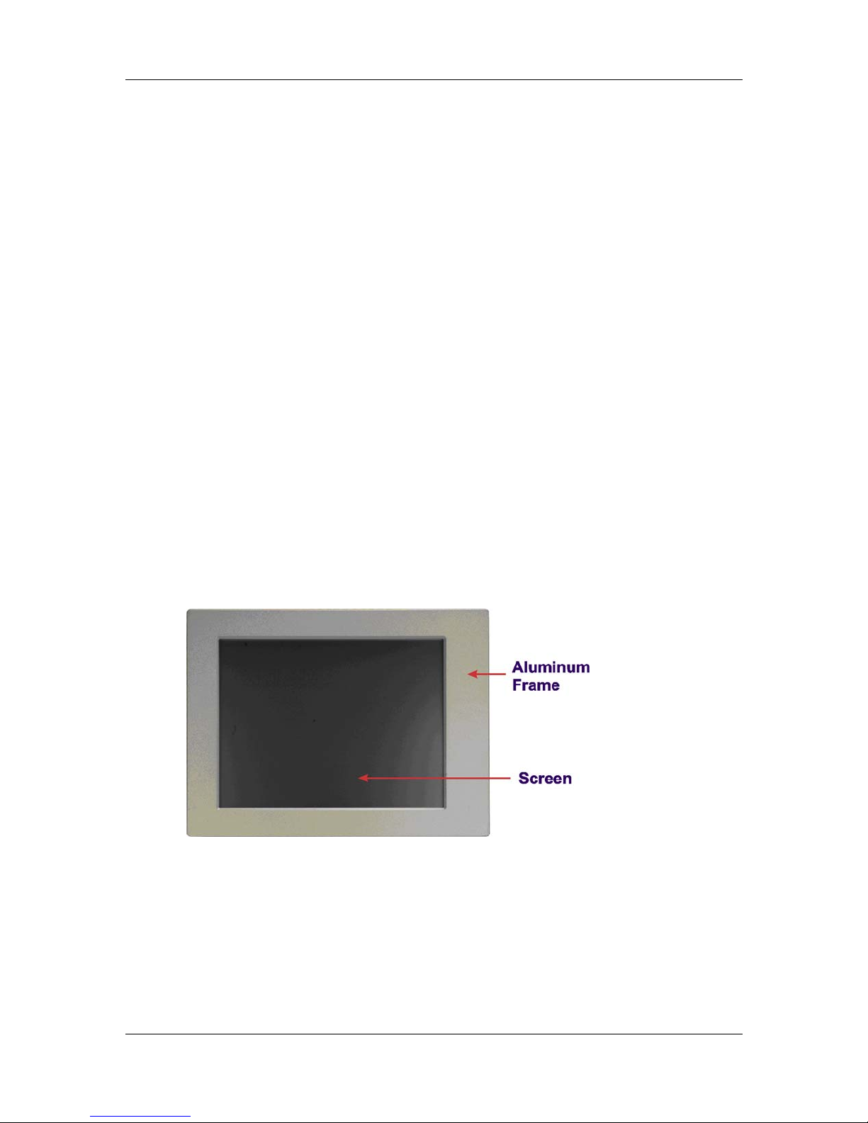
1.2.1 Front Panel
The front panel of the STE 1xGTx (Figure 1-2) is a flat panel TFT LCD screen surrounded
by an aluminum frame.
Figure 1-2: Front View
4 ©Copyright 2011 CyberResearch, Inc.
Page 23
CyberResearch® Panel PCs STE 1xGTx Series
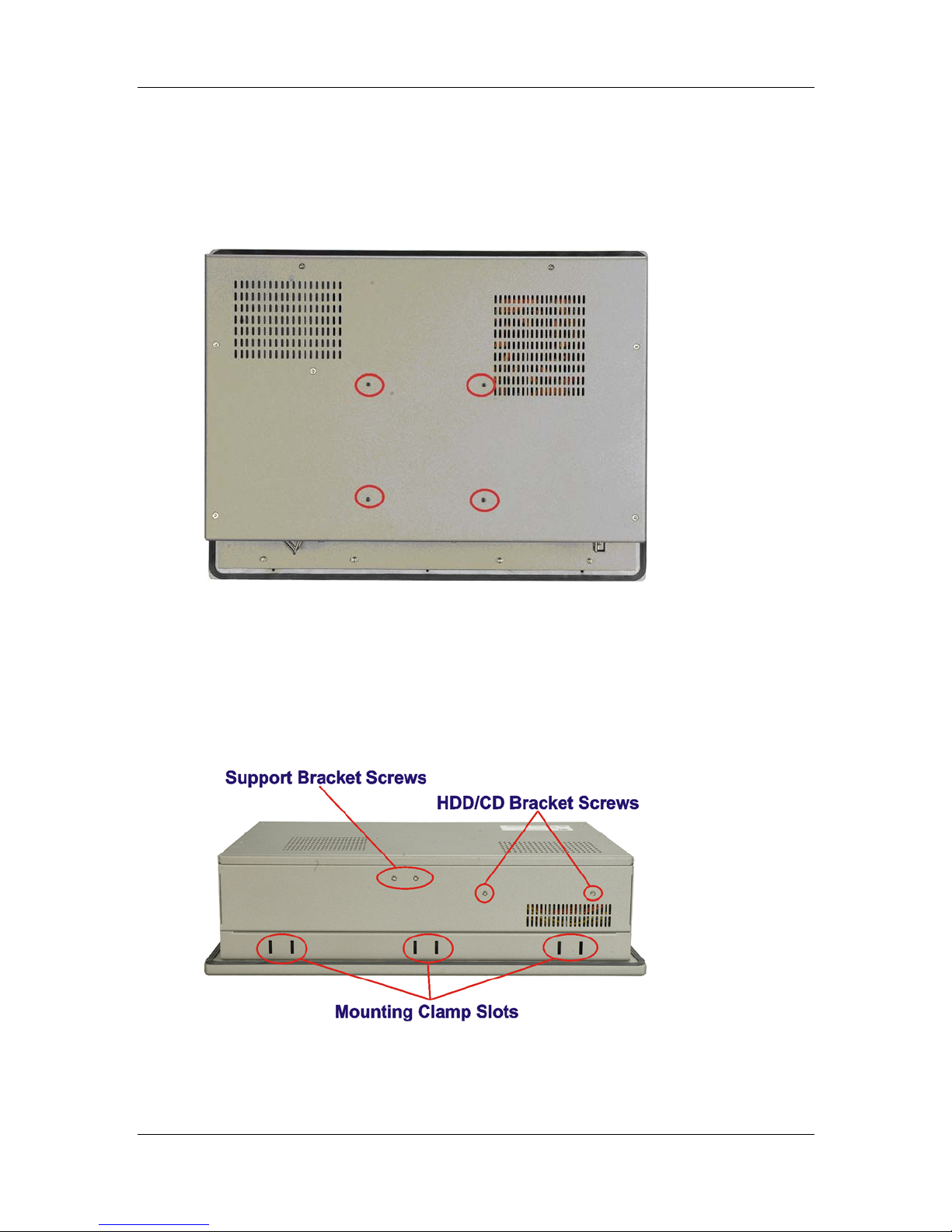
1.2.2 Rear Panel
The rear panel has a fan vent, four VESA standard mounting holes and several retention
screw holes. The VESA mounting holes are circled in Figure 1-3.
Figure 1-3: STE 1xGTx Rear View
1.2.3 Top Panel
The top panel has two fan vents, eight mounting clamp slots and three retention screws
for securing the drive bay bracket. The retention screws are circled in Figure 1-4 below.
Figure 1-4: STE 1xGTx Top View
CyberResearch, Inc. 5
25 Business Park Drive P: (203) 643-5000; F: (203) 643-5001
Branford, CT USA www.cyberresearch.com
Page 24
STE 1xGTx Series CyberResearch® Panel PCs
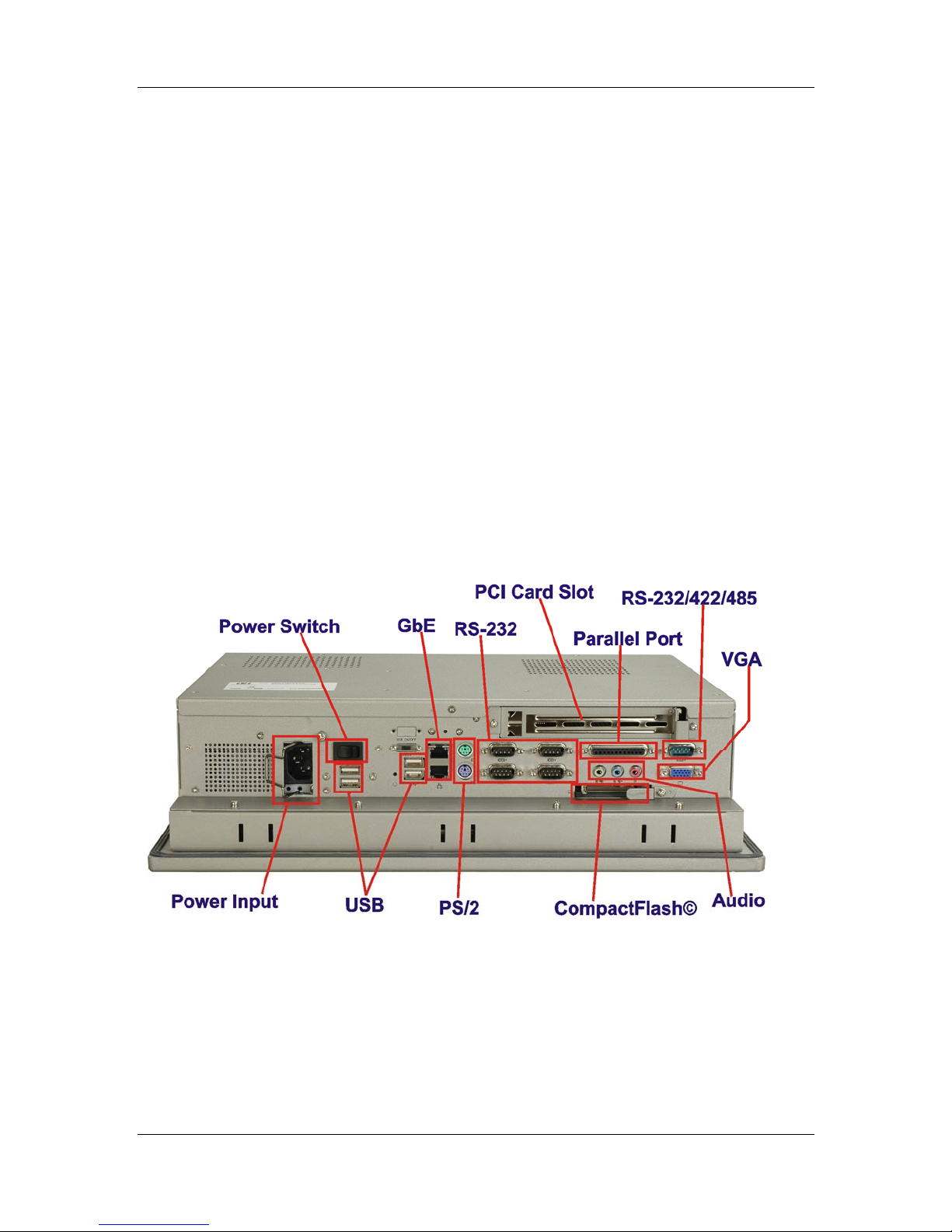
1.2.4 Bottom Panel
The bottom panel shown in Figure 1-5 has the following interfaces:
1 x Power input connector
1 x Power switch
4 x USB connectors
1 x Reset button
2 x RJ-45 GbE connectors
1 x PS/2 mouse connector
1 x PS/2 keyboard connector
5 x Serial port (COM) connectors
1 x PCI add-on card slot
1 x Parallel port connector
3 x Audio jacks
1 x VGA connector
1 x CompactFlash® slot
Figure 1-5: Bottom View
6 ©Copyright 2011 CyberResearch, Inc.
Page 25
CyberResearch® Panel PCs STE 1xGTx Series
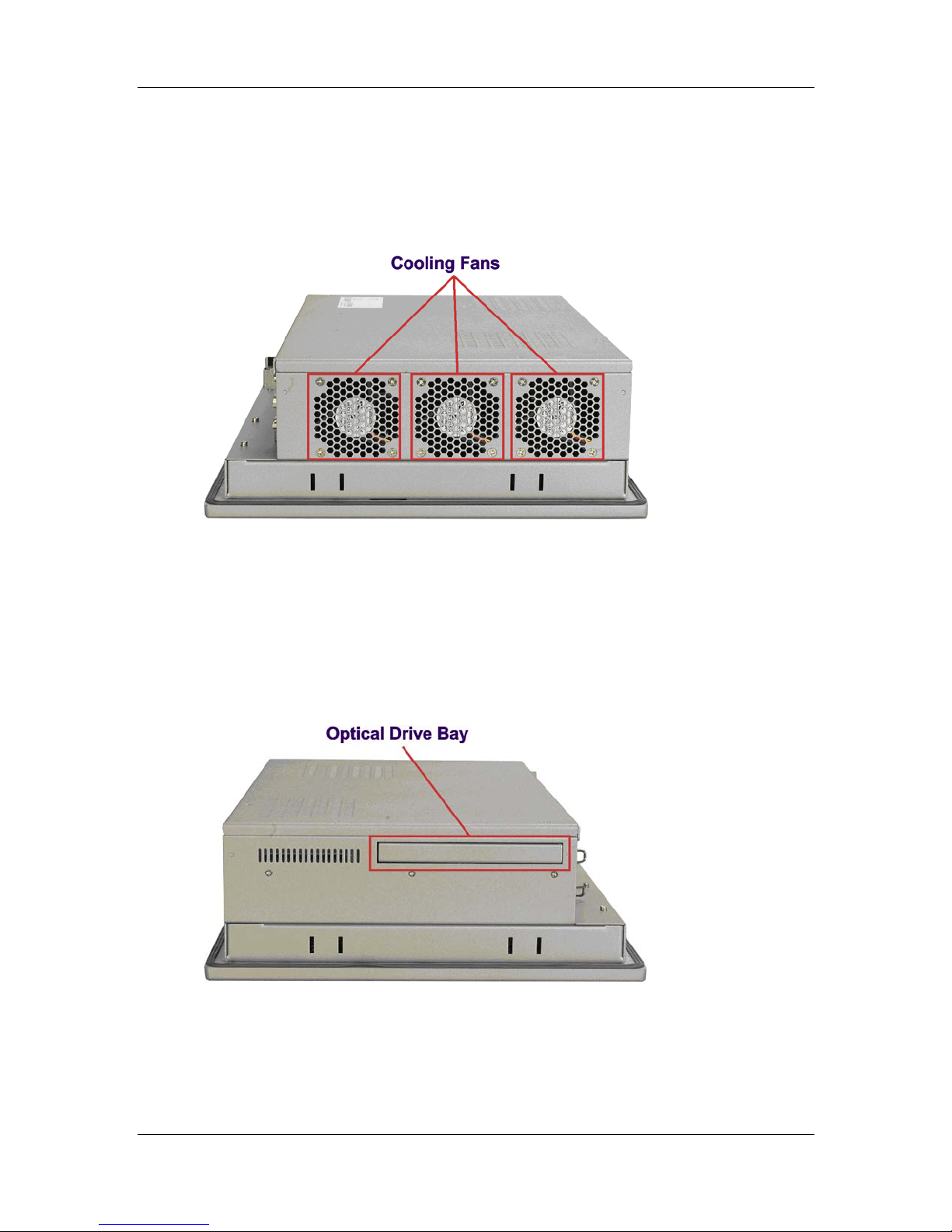
1.2.5 Left Panel
The left side panel has two fan vents and four retention screws for securing the two
internal fans. The retention screws are circled in Figure 1-6.
Figure 1-6: Left View
1.2.6 Right Panel
The right side panel provides access to a slim type CD drive bay and a FDD drive bay
shown in Figure 1-7.
Figure 1-7: Right View
CyberResearch, Inc. 7
25 Business Park Drive P: (203) 643-5000; F: (203) 643-5001
Branford, CT USA www.cyberresearch.com
Page 26
STE 1xGTx Series CyberResearch® Panel PCs
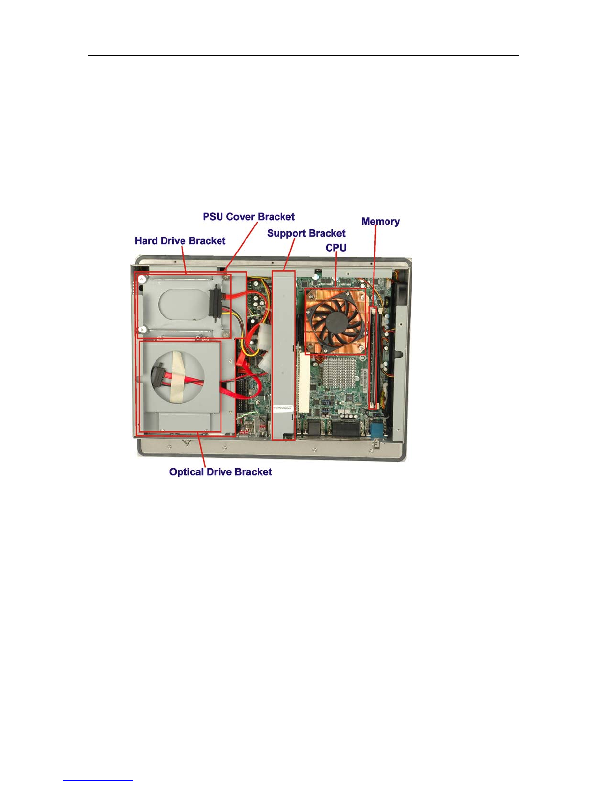
1.3 Internal Overview
The STE 1xGTx internal components are configured in three levels. The PSU cover
bracket to the left (Figure 1-8) supports the hard drive and optical drive brackets. Below
the PSU cover bracket is the power supply. On the same level as the power supply is the
motherboard. Below the motherboard and PSU level is an LCD panel. An overview picture
of the internal components is shown in Figure 1-8 below.
Figure 1-8: Internal Components
8 ©Copyright 2011 CyberResearch, Inc.
Page 27

CyberResearch® Panel PCs STE 1xGTx Series
Chapter
2
2 Specifications
CyberResearch, Inc. 9
25 Business Park Drive P: (203) 643-5000; F: (203) 643-5001
Branford, CT USA www.cyberresearch.com
Page 28

STE 1xGTx Series CyberResearch® Panel PCs
2.1 Introduction
The STE 1xGTx flat panel PC has the following preinstalled components:
1 x Motherboard
1 x TFT LCD screen
1 x Power supply
2 x Cooling fans
The technical specifications for these components and the system are shown in the
sections below.
2.1.1 System Specifications
The technical specifications for the STE 1xGTx system are listed in Table 2-1.
SPECIFICATION DESCRIPTION
Front Panel Aluminum Front Panel meets IP 65 standard
Chassis Heavy-duty Steel
LCD Panel High luminance TFT LCD
Resolution STE 15GTx: 1024 x 768 (XGA)
STE 17GTx: 1280 x 1024 (SXGA)
STE 19GTx: 1280 x 1024 (SXGA)
Brightness STE 15GTx: 350 cd/m2
STE 17GTx: 300 cd/m2
STE 19GTx: 300 cd/m2
Contrast Ratio STE 15GTx: 700:1
STE 17GTx: 800:1
STE 19GTx: 800:1
LCD MTBF 50,000 hrs
Backlight MTBF 50,000 hrs
Viewing Angle (H/V) STE 15GTx: 140/125
10 ©Copyright 2011 CyberResearch, Inc.
STE 17GTx: 160/160
STE 19GTx: 160/160
Page 29

CyberResearch® Panel PCs STE 1xGTx Series
SPECIFICATION DESCRIPTION
Touch Screen Optional 5-wire resistive type touch screen with
RS-232 interface
Display Supports Dual Display
Add-On Card (Optional) One PCI card
Drive Bay One 2.5” HDD bay with anti-shock
One slim type CD drive bay
One slim type FDD bay
One CompactFlash® slot
Power Supply Input voltage: 90~265 V AC, 50~60 Hz
Output rating: 180 W
Output voltage:
+3.3 V @ 16.8A
+5 V @ 12A
+12 V @ 10A
-12 V @ 0.8A
+5 VSB @ 2A
Input voltage: 24 VDC (18-36 VDC)
Output rating: 200 W
Output voltage:
+3.3 V @ 12A
+5 V @ 12A
+12 V @ 15.4A
-12 V @ 0.5A
+5 VSB @ 2A
Mounting Feature Panel, Arm, Wall, or Rack/Cabinet
Color Silver (PANTONE PMS-8001)
Operating Temperature 0~50˚C
Relative Humidity 5 ~ 85%, non-condensing
Vibration 5 - 17Hz, 0.1” double am plitude displacement
CyberResearch, Inc. 11
25 Business Park Drive P: (203) 643-5000; F: (203) 643-5001
Branford, CT USA www.cyberresearch.com
17 - 640Hz, 1.5G acceleration, peak to peak
Page 30
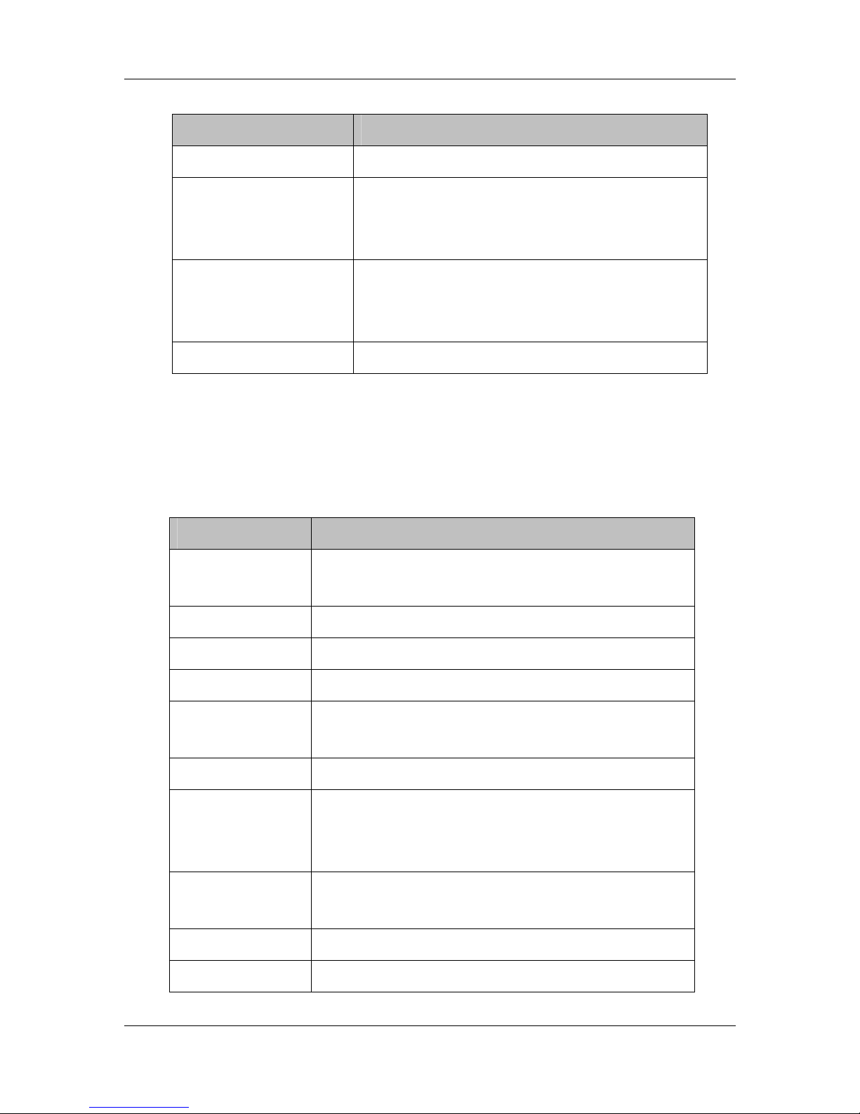
STE 1xGTx Series CyberResearch® Panel PCs
SPECIFICATION DESCRIPTION
Shock 10G Accelera tion, peak to peak (11ms)
Dimensions (W x D x H) STE 15GTx: 410 mm x 309 mm x 110.5 mm
STE 17GTx: 452 mm x 356 mm x 115 mm
STE 19GTx: 483 mm x 399 mm x 115.2 mm
Net/Gross Weight STE 15GTx: 7 kg/11 kg
STE 17GTx: 8 kg/12 kg
STE 19GTx: 12.6 kg/18.2 kg
Environment RoHS Compliant
Table 2-1: STE 1xGTx Specifications
2.1.2 Motherboard Specifications
The technical specifications for the STE 1xGTx motherboard are listed in Table 2-2.
SPECIFICATION DESCRIPTION
CPU LGA775
Intel® 1.8 GHz Dual Core
Northbridge Intel® 945G
Southbridge Intel® ICH7
Max. FSB 533 MHz
Memory 2 x 2.0 GB (max) 400/533/667 MHz DDR2 DIMM sockets
up to 4.0 GB (total)
BIOS AMI BIOS Label
Display CRT integrated in Intel® 945G
LVDS Dual 18/24-bit TTL LCD implemented through a
Chrontel CH7308B LVDS chipset
Expansion Interface 1 x PCI slot
Audio HD Audio
Ethernet 2 x Broadcom BCM5787M GbE controller
12 ©Copyright 2011 CyberResearch, Inc.
1 x PCIe slot
Page 31

CyberResearch® Panel PCs STE 1xGTx Series
SPECIFICATION DESCRIPTION
COM 1 x RS-232/422/485 port
5 x RS-232 ports (1 used internally for touch screen)
USB 2.0 6 x USB 2.0 ports
Drive Interfaces 2 x SATA drive connectors
LPT 1 x Parallel port
KB/ MS 2 x PS/2 connector
IrDA 1 x IrDA interface
Table 2-2: Motherboard Specifications
2.1.3 Flat Panel Screen
The STE 1xGTx comes with a flat panel TFT LCD screen. Screen specifications for each
model are detailed below.
2.1.3.1 STE 15GTx Screen
The STE 15GTx comes with a 15” TFT LCD monitor at the front of the flat panel PC. The
specifications for the LCD monitor are shown in Table 2-3 below.
SPECIFICATION DETAILS
Model
Size
Resolution
Active Area (mm)
Pixel Pitch (mm)
Mode
Number of Colors
AUO-G150XG01
15”
XGA (1024 x 768)
304.1 x 228.1
0.297
TN
262K
Color Saturation (%)
View Angel (H/V)
Brightness (cd/m2)
CyberResearch, Inc. 13
25 Business Park Drive P: (203) 643-5000; F: (203) 643-5001
Branford, CT USA www.cyberresearch.com
60
120/100
350
Page 32

STE 1xGTx Series CyberResearch® Panel PCs
SPECIFICATION DETAILS
Contrast Ratio
Response Time (ms) (at 25°C)
Power Consumption (W)
Interface
Supply Voltage (V)
Backlight
Outline Dimensions (mm)
Weight (g)
400:1
16
11.5
1ch L V DS
3.3
2 CCFL
326.5 x 253.5 x 12.0
1100
Table 2-3: 15” TFT LCD Monitor Specifications
2.1.3.2 STE 17GTx Screen
The STE 17GTx comes with a 17” TFT LCD monitor at the front of the flat panel PC. The
specifications for the LCD monitor are shown in Table 2-4 below.
SPECIFICATION DETAILS
Model
Size
Resolution
Active Area (mm)
Pixel Pitch (mm)
Mode
Number of Colors
Color Saturation (%)
View Angel (H/V)
Brightness (cd/m2)
Contrast Ratio
AUO-M170EG01 V8
17”
SXGA (1280 x 1024)
337.9 x 270.3
0.264
TN
16.2M
72
140 / 130
300
500 : 1
14 ©Copyright 2011 CyberResearch, Inc.
Page 33

CyberResearch® Panel PCs STE 1xGTx Series
SPECIFICATION DETAILS
Response Time (ms) (at 25°C)
Power Consumption (W)
Interface
Supply Voltage (V)
Backlight
Outline Dimensions (mm)
Weight (g)
8
25.8
2ch L V DS
5
4 CCFL
358.5 x 296.5 x 17.0
1900
Table 2-4: 17” TFT LCD Monitor Specifications
2.1.3.3 STE 19GTx Screen
The STE 19GTx comes with a 19” TFT LCD monitor at the front of the flat panel PC. The
specifications for the LCD monitor are shown in Table 2-5 below.
SPECIFICATION DESCRIPTION
Model AUO-M190EG02
Size 19”
Resolution SXGA (1280 x 1024)
Active Area (mm) 376.32 x 301.06
Pixel Pitch (mm) 0.294
Mode TN
Number of Colors 16.2M
Color Saturation (%) 72
View Angel (H/V) 160 / 160
Brightness (cd/m2) 300
Contrast Ratio 700 : 1
Response Time (ms) (at 25°C) 6
Power Consumption (W) 28
CyberResearch, Inc. 15
25 Business Park Drive P: (203) 643-5000; F: (203) 643-5001
Branford, CT USA www.cyberresearch.com
Page 34

STE 1xGTx Series CyberResearch® Panel PCs
SPECIFICATION DESCRIPTION
Interface 2ch LVDS
Supply Voltage (V) 5
Backlight 4 CCFL
Outline Dimensions (mm) 396.0 x 324.0 x 17.5
Weight (g) 2500
Table 2-5: 19” TFT LCD Monitor Specifications
2.1.4 Power Supply
The STE 1xGTx flat panel PC comes with either a 180 W AC-DC 1U (model STx 1xGTA),
or a 200 W DC 1U (model STx 1xGTC) RoHS compliant ATX power supply. The PSUs
have an MTBF greater than 100,000 hours.
WARNING:
Under no circumstances is the PSU case to be opened. The PSU
module is not user serviceable and there are dangerous high-voltages
inside the case. If there are any problems with the PSU module, please
contact CyberResearch, Inc. immediately.
16 ©Copyright 2011 CyberResearch, Inc.
Page 35

CyberResearch® Panel PCs STE 1xGTx Series
2.1.4.1 STE 1xGTA Power Supply
Specifications for the STE 1xGTA PSU module are shown in (Table 2-6).
Specification Rating
INPUT Voltage AC90 V ~ 265 V AC Full Range
Frequency 47 ~ 63Hz
Input Current 4A(RMS)@115 VAC
2A(RMS)@230 VAC
Inrush Current 50 A Max for 115 VAC
80 A Max for 230 VAC
OUTPUT Voltage (V) +3.3 V +5 V +12 V -12 V 5 VSB
Min. Load (A) 0.3A 0.3A 1.5A 0A 0A
Max. Load (A) 16.8A 12A 10A 0.8A 2A
Ripple and Noise (mV) 50mV 50mV 120mV 120mV 50mV
+3.3 V & +5 V≦61 W, +3.3 V & +5 V & +12 V≦160 W
GENERAL Watt 180 W
PFC Active
Hold-up time 17ms minimum
Efficiency 68%
MTBF 100,000hrs
Temperature 0~50°C (Operating)
Humidity 5 –95% RH, Non-condensing
Dimension 150 mm (W) x 81.5 mm (H) x 40.5 mm (D)
Table 2-6: STE 1xGTA Power Supply Specifications
CyberResearch, Inc. 17
25 Business Park Drive P: (203) 643-5000; F: (203) 643-5001
Branford, CT USA www.cyberresearch.com
-20~80°C (Storag e)
(Operating & Storage)
Page 36

STE 1xGTx Series CyberResearch® Panel PCs
2.1.4.2 STE 1xGTC Power Supply
Specifications for the STE 17GTC PSU module are shown in (Table 2-7).
Specification Rating
INPUT Voltage 18 VDC ~ 36 VDC Full Range
Input Current 15A
Inrush Current 100A
OUTPUT Voltage (V) +3.3 V +5 V +12 V -12 V 5 VSB
Min. Load (A) 0.0A 1.0A 0.5A 0.0A 0.0A
Max. Load (A) 12A 12A 15.4A 0.5A 2.0A
Ripple and Noise (mV) 50mV 50mV 120mV 120mV 50mV
GENERAL Watt 200 W
PFC Active
Hold-up time 20ms minimum
Efficiency 78%
MTBF 100,000hrs
Humidity 5 –95% RH, Non-condensing (Operating & Storage)
Dimension 150 mm (W) x 81.5 mm (H) x 40.3 mm (D)
Table 2-7: STE 17GTC Power Supply Specifications
2.2 Dimensions
The dimensions of the STE 1xGTx are shown in the sections below.
+3.3 V & +5 V≦80 W; +3.3 V & +5 V & +12 V≦184 W
Temperature 0~50°C (Operating); -20~80°C (Storage)
18 ©Copyright 2011 CyberResearch, Inc.
Page 37

CyberResearch® Panel PCs STE 1xGTx Series
2.2.1 STE 15GTx Dimensions
The dimensions of the STE 15GTx flat panel PC are shown in Figure 2-1 below.
Figure 2-1: STE 15GTx Dimensions (units in mm)
CyberResearch, Inc. 19
25 Business Park Drive P: (203) 643-5000; F: (203) 643-5001
Branford, CT USA www.cyberresearch.com
Page 38

STE 1xGTx Series CyberResearch® Panel PCs
2.2.2 STE 17GTx Dimensions
The dimensions of the STE 17GTx flat panel PC are shown in Figure 2-2 below.
Figure 2-2: STE 17GTx Dimensions (units in mm)
20 ©Copyright 2011 CyberResearch, Inc.
Page 39

CyberResearch® Panel PCs STE 1xGTx Series
2.2.3 STE 19GTx Dimensions
The dimensions of the STE 19GTx flat panel PC are shown in Figure 2-3 below.
Figure 2-3: STE 19GTx Dimensions (units in mm)
CyberResearch, Inc. 21
25 Business Park Drive P: (203) 643-5000; F: (203) 643-5001
Branford, CT USA www.cyberresearch.com
Page 40

STE 1xGTx Series CyberResearch® Panel PCs
2.3 Motherboard
The STE 1xGTx flat screen PC contains a motherboard. The motherboard is the heart of
any computer and is responsible for transmitting, receiving and processing dat a as well a s
driving the different on-board devices. This chapter gives a brief introduction to the STE
1xGTx motherboard.
Figure 2-4: STE 1xGTx Motherboard
2.4 CPU Support
The STE 1xGTx motherboard supports LGA775 Intel® 1.8 GHz Dual Core processors.
2.5 System Chipsets
The following chipsets are preinstalled on the board:
Northbridge: Intel® 945G
Southbridge: Intel® ICH7
Specifications of these two chipsets are listed in the subsections below.
22 ©Copyright 2011 CyberResearch, Inc.
Page 41

CyberResearch® Panel PCs STE 1xGTx Series
2.5.1 Intel® 945G Northbridge Chipset
The Intel® 945G Northbridge chipset comes with the following features:
Supports the Intel® 1.8 GHz Dual Core processor with Intel NetBurst®
microarchitecture
400 MHz or 533 MHz system bus delivers a high-bandwidth connection
between the processor and the platform
Integrated graphics utilizing Intel® Extreme Graphics 2 technology
Display
o Analog display support
o Dual independent pipe support
o DVO (DVOB and DVOC) support
o Dedicated Local Flat Panel (LFP) LVDS interface
Intel® Embedded Graphics Drivers
o Graphics interface support
o Multi-monitor support
o Dynamic display-mode support
o Embedded video BIOS
2.5.2 ICH7 Southbridge Chipset
The ICH7 Southbridge chipset comes with the following features:
PCI Bus Interface
o New: Supports PCI Revision 2.3 Specification at 33 MHz
o 6 available PCI REQ/GNT pairs
o One PCI REQ/GNT pair can be given higher arbitration priority (intended
for external 1394 host controller)
o Support for 44-bit addressing on PCI using DAC protocol
Integrated LAN Controller
o Integrated ASF Management Controller
o WfM 2.0 and IEEE 802.3 Compliant
o LAN Connect Interface (LCI)
o 10/100/1000 Mbit/sec Ethernet Support
Integrated Serial ATA Host Controllers
CyberResearch, Inc. 23
25 Business Park Drive P: (203) 643-5000; F: (203) 643-5001
Branford, CT USA www.cyberresearch.com
Page 42

STE 1xGTx Series CyberResearch® Panel PCs
o Independent DMA operation on two ports.
o Data transfer rates up to 1.5 Gb/s (150 MB/s).
Integrated IDE Controller
o Supports “Native Mode” Register and Interrupts
o Independent timing of up to 4 drives
o Ultra ATA/100/66/33, BMIDE and PIO modes
o Tri-state modes to enable swap bay
Interrupt Controller
o Supports up to 8 PCI interrupt pins
o Supports PCI 2.3 Message Signaled Interrupts
o Two cascaded 82C59 with 15 interrupts
o Integrated I/O APIC capability with 24 interrupts
o Supports Front Side Bus interrupt delivery
High-Precision Event Timers
1.5 V operation with 3.3 V I/O
o 5 V tolerant buffers on IDE, PCI, USB Overcurrent and Legacy signals
Integrated 1.5 V Voltage Regulator (INTVR) for the Suspend wells
Enhanced DMA Controller
o Two cascaded 8237 DMA controllers
o PCI DMA: Supports PC/PCI — Includes two PC/PCI REQ#/GNT# pairs
o Supports LPC DMA
o Supports DMA Collection Buffer to provide Type-F DMA performance for
all DMA channels
Real-Time Clock
o 256-byte battery-backed CMOS RAM
o Integrated oscillator components
o Lower Power DC/DC Converter implementation
2.6 Graphics Support
The ATi M690T Northbridge chipset has an integrated graphics engine that supports the
following display devices:
Analog CRT
Digital LVDS
24 ©Copyright 2011 CyberResearch, Inc.
Page 43

CyberResearch® Panel PCs STE 1xGTx Series
2.6.1 Analog CRT Support
The VGA port connects a peripheral monitor to the STE 1xGTx system. A DB-15 VGA
connector on the external peripheral interface connector panel is interfaced to the Intel®
945G Northbridge. The Intel® 945G supports analog CRT monitors with the following
features:
Supports max DAC frequency up to 400 MHz
24-bit RAMDAC support
DDC2B compliant
Up to 2048 x 1536 mode support
2.6.2 LVDS Support
The LVDS connector drives the built-in LCD panel. The 30-pin LVDS crimp connector is
connected to the Chrontel CH7308B chipset, which is connected to the Intel® 945G
through the SDVO interface.
18/24-bit outputs
Up to 140 megapixels per second
2.7 Memory
All processors supported by the STE 1xGTx have their own internal DDR2 memory
controller. The DDR2 controller has the following features:
Low-latency, high-bandwidth
800 MHz 128-bit DDR2 SDRAM controller
Supports one un-buffered DDR2 SO-DIMM
Each SO-DIMM has a maximum capacity of 1.0 GB
The DDR2 controller on the processor is interfaced to one SO-DIMM socket on the STE
1xGTx.
CyberResearch, Inc. 25
25 Business Park Drive P: (203) 643-5000; F: (203) 643-5001
Branford, CT USA www.cyberresearch.com
Page 44

STE 1xGTx Series CyberResearch® Panel PCs
Figure 2-5: SO-DIMM Socket
2.8 Storage
There following storage options are available:
CompactFlash®
SATA hard dri v e
2.8.1 CompactFlash
The CompactFlash® socket supports standard CompactFlash® Type I and
CompactFlash® Type II cards. The chipset flash interface is multiplexed with an IDE
interface and can be connected to an array of industry standard NAND Flash or NOR
Flash devices. The CompactFlash® slot location is shown below.
®
26 ©Copyright 2011 CyberResearch, Inc.
Page 45

CyberResearch® Panel PCs STE 1xGTx Series
Figure 2-6: CompactFlash® Slot
2.8.2 SATA Hard Drive
The integrated SATA controller supports two SATA drives with independent DMA
operations. One SATA port is implemented internally for the internal 2.5” SATA hard drive.
The second SATA port is implemented on the external co nnector panel through an eSATA
connector. SATA controller specifications are listed below.
Supports two SATA drives
Supports 3.0 Gb/s data transfer speeds
Supports Serial ATA Specification, Revision 1.0a
CyberResearch, Inc. 27
25 Business Park Drive P: (203) 643-5000; F: (203) 643-5001
Branford, CT USA www.cyberresearch.com
Page 46

STE 1xGTx Series CyberResearch® Panel PCs
Figure 2-7: SATA Hard Drive Slot
2.9 Expansion Slots
The STE 1xGTx includes either a PCI or PCIe x4 expansion card slot. The expansion card
slots add additional functionality to the STE 1xGTx.
Figure 2-8: Expansion Card Slot
PCI cards available for the STE 1xGTx include:
SCSI adapter cards
28 ©Copyright 2011 CyberResearch, Inc.
Page 47

CyberResearch® Panel PCs STE 1xGTx Series
Ethernet adapter cards
Modem cards
Sound cards
PCIe x4 cards available for the STE 1xGTx include:
Gigabit Ethernet adapter cards
SATA II / RAID controller cards
TV tuner cards
Graphics cards
Firewire & USB cards
2.10 External Device Connectors
The external device connectors allow external components to be attached to the STE
1xGTx. The external communications device connectors are shown in the sections below.
2.10.1 USB 2.0 Ports
USB connections provide fast data transmission to external devices including USB flash
disks.
Figure 2-9: USB Ports
Some of the features of the USB ports include
USB 2.0 compliant
Support for low speed (1.5 Mb/s), full speed (12 Mb/s) and hi-speed
(480 Mb/s) USB devices
Hotplugging capabilities
CyberResearch, Inc. 29
25 Business Park Drive P: (203) 643-5000; F: (203) 643-5001
Branford, CT USA www.cyberresearch.com
Page 48

STE 1xGTx Series CyberResearch® Panel PCs
2.10.2 Serial Ports
Serial ports provide communications to external devices. Four of the external serial ports
provide short-range communications, while one provides for longer range communicatio n.
Figure 2-10: Serial Ports
Some features of the serial ports include:
RS-232 transmission protocol for easy connection to devices with a standard
RS-232 interface
RS-422 and RS-485 transmission capabilities for longer dist ance
connections.
2.10.3 Parallel Port
The parallel port can be programmed for machine control, or used in the standard setup
for parallel port printers and other devices that use a standard parallel port.
Figure 2-11: Parallel Port
Some of the features of the parallel port include:
Programmable pin functions for customized applications
30 ©Copyright 2011 CyberResearch, Inc.
Page 49

CyberResearch® Panel PCs STE 1xGTx Series
Standard setup connects to devices with a standard parallel port, like printers
2.11 Gigabit Ethernet
The Broadcom BCM5787M PCI Express (PCIe) GbE controller is a 10/100/1000BASE-T
Ethernet LAN controller. The BCM5787M combines a triple-speed IEEE 802.3 compliant
Media Access Controller (MAC) with a triple-speed Ethernet transceiver, a PCIe bus
interface, and an on-chip buffer memory.
Figure 2-12: Ethernet
Some of the BCM5787 controller features are listed below:
Integrated 10/100/1000BASE-T transceiver
Automatic MDI crossover function
PCIe v1.0a
10/100/1000BASE-T full/half-duplex MAC
Wake on LAN support meet ing the ACPI requirements
Statistics for SNMP MIB II, Ethernet-like MIB, and Ethernet MIB (802.3z,
clause 30)
Serial EEPROM or serial flash support
JTAG support
2.12 Front Panel
The front panel of the STE 1xGTx consists of an LCD monitor and a touch screen panel.
CyberResearch, Inc. 31
25 Business Park Drive P: (203) 643-5000; F: (203) 643-5001
Branford, CT USA www.cyberresearch.com
Page 50

STE 1xGTx Series CyberResearch® Panel PCs
2.12.1 Flat Screen
The STE 1xGTx comes with a TFT LCD monitor. The tough construction of the TFT
monitor allows the STE 1xGTx to withstand the conditions it is likely to be exposed to
during regular use. Some of the specifications of the TFT monitors are shown below:
Pixel pitch of 0.297 mm or less
700:1 contrast ratio or better
300 cd/m
2
or greater
8 msec optical response time or less
o
0
C to 50oC operating temperature
2.12.2 Touch Screen
The touch screen panel on the STE 1xGTx allows complete user interaction without the
need for a keyboard or mouse. Some of the features of the touch panel are listed below.
5-wire analog resistive type
78% transmission
Control chipset built onto the motherboard
-10
o
C to 50oC operating temperature
7 V maximum voltage
2.13 Customization
Some of the peripheral device connectors are not connected to any devices. These
connectors are reserved for customizations. For a customized option, please contact
CyberResearch, Inc.
32 ©Copyright 2011 CyberResearch, Inc.
Page 51

CyberResearch® Panel PCs STE 1xGTx Series
Chapter
3
3 Unpacking
CyberResearch, Inc. 33
25 Business Park Drive P: (203) 643-5000; F: (203) 643-5001
Branford, CT USA www.cyberresearch.com
Page 52

STE 1xGTx Series CyberResearch® Panel PCs
3.1 Anti-static Precautions
WARNING!
Failure to take ESD precautions during the installation of the STE
1xGTx may result in permanent damage to the STE 1xGTx and severe
injury to the user.
Electrostatic discharge (ESD) can cause serious damage to electronic components,
including the STE 1xGTx. Dry climates are especially susceptible to ESD. It is critical that
the following anti-static precautions are strictly adhered to whenever handling the STE
1xGTx or any other electrical component.
Wear an anti-static wristband - Wearing a simple anti-static wristband can
help to prevent ESD from damaging the STE 1xGTx.
Self-grounding - Touch a grounded conducting material before handling and
periodically while handling the STE 1xGTx.
Use an anti-static pad - When configuring the STE 1xGTx, place it on an
antic-static pad to reduce the possibility of ESD damage.
Only handle the edges of the STE 1xGTx - When handling the STE 1xGTx,
hold it by its edges.
3.2 Unpacking Precautions
When the STE 1xGTx is unpacked, please do the following:
Follow the anti-static precautions outlined in Section 3.1.
Make sure the packing box is facing upwards so the STE 1xGTx does not fall
out of the box.
Make sure all the components shown in Section 3.3 are present.
34 ©Copyright 2011 CyberResearch, Inc.
Page 53

CyberResearch® Panel PCs STE 1xGTx Series
3.3 Package Contents
NOTE:
If any components listed in the checklist below are missing, do not
proceed with the installation. Contact a CyberResearch sales engineer
immediately via our website www.cyberresearch.com
643-5000, or e-mail:sales@cyberresearch.com.
The STE 1xGTx is shipped with the following components (many of the compon ents liste d
below come pre-installed):
Quantity Item and Part Number Image
1 STE 1xGTx
1 Hard drive bracket
1 IDE cable (40-pin to 40-pin)
, by phone: (203)
1 IDE cable (44-pin to 44-pin)
1 Jumper pack
1 Wall mounting kit
CyberResearch, Inc. 35
25 Business Park Drive P: (203) 643-5000; F: (203) 643-5001
Branford, CT USA www.cyberresearch.com
Page 54

STE 1xGTx Series CyberResearch® Panel PCs
Quantity Item and Part Number Image
1 Power cord
1 Screw set
1 IDE adapter
(for slim DVD/CD-ROM)
1 Driver CD/DVD
1 Touch pen
Table 3-1: Package List Contents
36 ©Copyright 2011 CyberResearch, Inc.
Page 55

CyberResearch® Panel PCs STE 1xGTx Series
Chapter
4
4 Installation and
Configuration
CyberResearch, Inc. 37
25 Business Park Drive P: (203) 643-5000; F: (203) 643-5001
Branford, CT USA www.cyberresearch.com
Page 56

STE 1xGTx Series CyberResearch® Panel PCs
4.1 Installation Precautions
When installing the STE 1xGTx, please follow the precautions listed below:
Turn power off: When installing the STE 1xGTx make sure the power is off.
Failing to turn off the power may cause severe injury to the body and/or
damage to the system.
Certified Engineers: Only certified engineers should install and modify
on-board functions.
Mounting: The STE 1xGTx is a heavy device. When mounting the system
onto a rack, panel, wall or arm please make sure that at least two people are
assisting with the procedure.
Anti-static Di scharge: If a user open the rear panel of the STE 1xGTx, to
configure the jumpers or plug in added peripheral devices, ground themselves
first and wear and anti-static wristband.
4.2 Preinstalled Components
The following components are all preinstalled.
Motherboard
TFT LCD
Touch screen
Power switch
Power supply
Inverter board
PCI riser card
System cooling fans
CPU
HDD
CD/DVD drive
DIMM
Removal and reinstallation of some of the components are described in Chapter 4.
38 ©Copyright 2011 CyberResearch, Inc.
Page 57

CyberResearch® Panel PCs STE 1xGTx Series
4.3 Installation and Configuration Steps
The following installation steps must be followed.
Step 1: Unpack the STE 1xGTx.
Step 2: Set the jumper settings.
Step 3: Install HDD, CompactFlash® and CD/DVD drive.
Step 4: Mount the STE 1xGTx flat panel PC.
Step 5: Connect peripheral devices to the bottom panel of the STE 1xGTx.
Step 6: Configure the system.Step 0:
CyberResearch, Inc. 39
25 Business Park Drive P: (203) 643-5000; F: (203) 643-5001
Branford, CT USA www.cyberresearch.com
Page 58

STE 1xGTx Series CyberResearch® Panel PCs
4.4 Remove the Back Cover
Remove all the retention screws on the back cover. Lift the cover up to remove
(Figure 4-1).
Figure 4-1: Back Cover Retention Screws
4.5 Jumper Settings
40 ©Copyright 2011 CyberResearch, Inc.
Page 59

CyberResearch® Panel PCs STE 1xGTx Series
NOTE:
A jumper is a metal bridge that is used to close an electrical circuit. It
consists of two metal pins and a small metal clip (often protected by a
plastic cover that slides over the pins to connect them. To
CLOSE/SHORT a jumper means connecting the pins of the jumper
with the plastic clip and to OPEN a jumper means removing the plastic
clip from a jumper.
The STE 17GTx motherboard comes with fifteen jumpers (Table 3-1).
Jumper Type Label
AT/ATX power sele ction 2-pin header AT_PWR_SW1
Clear CMOS 3-pin header JP2
Monitor Setup 8-pin header JP1
CompactFlash® card setup 2-pin header JP7
COM port pin-9 setting 6-pin header JP3, JP4, JP5, JP6,
JP8
COM5 RS-232/422/485 RX select 6-pin header J2
COM5 RS-422/485 TX select 6-pin header J3
COM5 D-SUB setup 12-pin header J4
COM5 termination resistor 2-pin header J5, J6
LCD voltage selection 6-pin header JP9
Touch screen selection 4-pin header J7
Table 4-1: Onboard Jumpers
4.5.1 AT/ATX Power Selection (AT_PWR_SW1)
The AT/ATX power selection switch selects AT or ATX power for the STE 1xGTx. ATX
power has more power saving capabilities than AT power.
CyberResearch, Inc. 41
25 Business Park Drive P: (203) 643-5000; F: (203) 643-5001
Branford, CT USA www.cyberresearch.com
Page 60

STE 1xGTx Series CyberResearch® Panel PCs
The AT/ATX selection jumper is connected to the AT/ATX switch on the I/O panel of the
STE 1xGTx.
AT_PWR_SW1 DESCRIPTION
Closed AT power
Open ATX power
Table 4-2: AT/ATX Power Selection
4.5.2 Clear CMOS Setup (JP2)
If the motherboard fails to boot due to improper BIOS settings, use this jumper to clear the
CMOS data and reset the system BIOS information. To do this, use the jumper cap to
close pins 2 and 3 for a few seconds then reinstall the jumper clip back to pins 1 and 2.
If the “CMOS Settings Wrong” message displays during the boot up process, try to co rre ct
the fault by pressing the F1 to enter the CMOS Setup menu. Then do one of the following:
Enter the correct CMOS setting
Load Optimal Defaults
After one of the above has been done, save the changes and exit the CMOS Setup menu.
JP2 DESCRIPTION
1-2 Normal (Default)
2-3 Clear CMOS
Table 4-3: Clear CMOS Jumper Settings
4.5.3 Monitor Setup (JP1)
WARNING:
Do not change these settings. They are set for the installed LCD panel.
Using different settings on the preinstalled monitor can destroy it.
42 ©Copyright 2011 CyberResearch, Inc.
Page 61

CyberResearch® Panel PCs STE 1xGTx Series
The monitor setup jumper sets the default settings for all monitors connected to the STE
1xGTx.
Pins 1-4 adjust the resolution of the screen.
JP1 (pins 1-4) LCD Resolution
OPEN 1024 x 768 (18-bit)
1-2 1024 x 768 (24-bit)
3-4 1280 x 1024 (36-bit)
1-2, 3-4 1280 x 1024 (48-bit)
Table 4-4: LCD Resolution Settings
Pins 5-8 adjust the monitor setup on the system.
JP1 (pins 5-8) Monitor Setup
OPEN LVDS + CRT
5-6 LVDS
7-8 CRT
5-6, 7-8 Auto
Table 4-5: Monitor Settings
4.5.4 CF Card Setup (JP7)
The CF Card Setup jumper configures a CF card as either the IDE slave or IDE master.
JP7 DESCRIPTION
Open Slave
Close Master
Table 4-6: CF Card Setup Jumper Settings
CyberResearch, Inc. 43
25 Business Park Drive P: (203) 643-5000; F: (203) 643-5001
Branford, CT USA www.cyberresearch.com
Page 62

STE 1xGTx Series CyberResearch® Panel PCs
4.5.5 COM Port RI and Voltage Selection (JP3, JP4, JP5, JP6, JP8)
Use the COM port settings jumpers to select the voltage of serial port pin 9.
JP3 COM1 Pin-9 Setting
1-2 12 V
3-4 RI
5-6 5 V
Table 4-7: COM1 RI and Voltage Selection Jumper
JP4 COM2 Pin-9 Setting
1-2 12 V
3-4 RI
5-6 5 V
Table 4-8: COM2 RI and Voltage Selection Jumper
JP5 COM3 Pin-9 Setting
1-2 12 V
3-4 RI
5-6 5 V
Table 4-9: COM3 RI and Voltage Selection Jumper
JP6 COM4 Pin-9 Setting
1-2 12 V
3-4 RI
5-6 5 V
Table 4-10: COM4 RI and Voltage Selection Jumper
JP8 COM5 Pin-9 Setting
1-2 12 V
3-4 RI
5-6 5 V
Table 4-11: COM5 RI and Voltage Selection Jumper
44 ©Copyright 2011 CyberResearch, Inc.
Page 63

CyberResearch® Panel PCs STE 1xGTx Series
4.5.6 COM5 RS-232/422/485 Settings
To enable RS-232, RS-422 or RS-485 on COM5, all the following jumpers should be
setup.
4.5.6.1 COM5 RS-232/422/485 RX Select (J2)
Jumper J2 sets the COM5 serial port as RS-232, RS-422 or RS-48 5.
J2 DESCRIPTION
1-2 RS232 (default)
3-4 RS422
5-6 RS485
Table 4-12: COM5 RS-232/422/485 RX Select
4.5.6.2 COM5 RS-422/485 TX Select (J3)
Jumper J3 sets the COM5 serial port as RS-422 or RS-485.
J3 DESCRIPTION
1-3, 2-4 RS422
3-5, 4-6 RS485
Table 4-13: COM5 RS-422/485 TX Select
4.5.6.3 COM5 D-Sub Pinout Selection (J4)
Jumper J4 sets the external COM5 serial port as RS-232 or RS-422/485.
J4 DESCRIPTION
1-2, 4-5, 7-8, 10-11 RS-232
2-3, 5-6, 8-9, 11-12 RS-422/485
Table 4-14: COM5 RS-422/485 TX Select
CyberResearch, Inc. 45
25 Business Park Drive P: (203) 643-5000; F: (203) 643-5001
Branford, CT USA www.cyberresearch.com
Page 64

STE 1xGTx Series CyberResearch® Panel PCs
4.5.6.4 COM5 Termination Resistors (J5, J6)
The termination resistors J5 and J6 can remedy communication errors for RS-422/485
setups with cables over 1.5 km in length
J5 J6 DESCRIPTION
Open Open No terminator resistor set
Closed Closed Termination resistor set
Table 4-15: COM5 RS-422/485 TX Select
4.5.7 LCD Voltage Settings (JP9)
WARNING:
Do not change these settings. They are set for the installed LCD panel.
Using different settings on the preinstalled monitor can destroy it.
The LCD setup sets the voltage and default monitor settings on the STE 1xGTx.
JP9 LCD Voltage
1-2 3.3 V
3-4 5 V
5-6 12 V
Table 4-16: LCD Voltage Settings
46 ©Copyright 2011 CyberResearch, Inc.
Page 65

CyberResearch® Panel PCs STE 1xGTx Series
4.5.8 Touch Screen Selection (JP7)
The touch screen selection jumper selects the type of touch screen panel connected to the
system.
JP7 DESCRIPTION
1-2 5-wire touch panel
2-3 closed 4-wire or 8-wire touch panel
Table 4-17: Touch Screen Selection
4.6 Drive Installation
The drive installation process is shown in the sections below. The installation process of
the following drives are shown.
4.6.1 Hard Drive Installation...................................................................47
4.6.2 Compa ctFla sh
®
Installation...........................................................50
4.6.3 CD/DVD Drive Installation.............................................................51
4.6.1 Hard Drive Installation
To install a HDD, please follow the steps below:
Step 1: Remove the back cover (Section 4.4).
Step 2: The HDD bracket is attached to the elevated platform by four retention screws.
Remove the four retention screws from the elevated platform (Figure 4-2).
CyberResearch, Inc. 47
25 Business Park Drive P: (203) 643-5000; F: (203) 643-5001
Branford, CT USA www.cyberresearch.com
Page 66

STE 1xGTx Series CyberResearch® Panel PCs
Figure 4-2: HDD Retention Screws
Step 3: Attach the SATA connector cable to the bracket.
Figure 4-3: HDD SATA Connector
Step 4: Attach the hard drive in the bracket. To do this, slide the hard drive onto the
bracket until it connects with the SATA connector at the back. Fa sten the four
retention screws on the side.
48 ©Copyright 2011 CyberResearch, Inc.
Page 67

CyberResearch® Panel PCs STE 1xGTx Series
Figure 4-4: HDD Retention Screws
Step 5: Install the hard drive bracket (with hard drive and SATA cable attached) into the
STE 1xGTx and fasten the four hard drive bracket screws.Step 0:
Figure 4-5: HDD Retention Screws
CyberResearch, Inc. 49
25 Business Park Drive P: (203) 643-5000; F: (203) 643-5001
Branford, CT USA www.cyberresearch.com
Page 68

STE 1xGTx Series CyberResearch® Panel PCs
4.6.2 CompactFlash® Installation
To install the CompactFlash® card, please follow the steps below:
Step 1: Undo the CompactFlash® slot cover screw and remove the CompactFlash®
cover plate.
Figure 4-6: CompactFlash® Cover Plate
Step 2: Insert the CompactFlash® card into the slot.
Figure 4-7: CompactFlash® Slot
50 ©Copyright 2011 CyberResearch, Inc.
Page 69

CyberResearch® Panel PCs STE 1xGTx Series
Step 3: Fasten the CompactFlash® cover plate.Step 0:
Figure 4-8: CompactFlash® Cover Plate
4.6.3 CD/DVD Drive Installation
To install a CD/DVD drive, please follow the steps below.
Step 1: Remove the back cover (Section 4.4).
Step 2: Attach the CD/DVD drive adapter to the CD/DVD-ROM if it is an IDE drive (if it is
a SATA drive, proceed to Step 5:). Attach a CD/DVD drive adapter to a CD/DVD
drive by aligning the two retention screw holes in the CD/DVD drive adapter with
the retention screw holes on the rear side of the CD/DVD drive.
Step 3: Place two spacers between the CD/DVD drive and CD/DVD drive adapter.
Step 4: Insert two retention screws and secure the adapter to the CD/DVD drive
(Figure 4-9).
CyberResearch, Inc. 51
25 Business Park Drive P: (203) 643-5000; F: (203) 643-5001
Branford, CT USA www.cyberresearch.com
Page 70

STE 1xGTx Series CyberResearch® Panel PCs
Figure 4-9: CD/DVD Drive Adapter Installation
Step 5: Undo the optical drive bracket screws and remove the optical drive bracket.
Figure 4-10: CD/DVD Drive Retention Screws
52 ©Copyright 2011 CyberResearch, Inc.
Page 71

CyberResearch® Panel PCs STE 1xGTx Series
Step 6: Remove the four screws from the optical drive bracket assembly. Remove the
blank drive plate.
Figure 4-11: Optical Drive Blank Plate Assembly
CyberResearch, Inc. 53
25 Business Park Drive P: (203) 643-5000; F: (203) 643-5001
Branford, CT USA www.cyberresearch.com
Page 72

STE 1xGTx Series CyberResearch® Panel PCs
Step 7: Install the optical drive in the same position as the previously removed blank
optical drive plate. Fasten the same four screws to attach the optical drive to the
bracket.
Figure 4-12: Optical Drive Screws
54 ©Copyright 2011 CyberResearch, Inc.
Page 73

CyberResearch® Panel PCs STE 1xGTx Series
Step 8: Attach the SA TA cable to the back of the optical drive and fasten the SATA cable
screws.
Figure 4-13: Optical Drive SATA Cable
Step 9: Reinstall the optical drive bracket into the STE 1xGTx and fasten the optical
bracket screws.Step 0:
Figure 4-14: Optical Drive Bracket Screws
CyberResearch, Inc. 55
25 Business Park Drive P: (203) 643-5000; F: (203) 643-5001
Branford, CT USA www.cyberresearch.com
Page 74

STE 1xGTx Series CyberResearch® Panel PCs
4.7 Mounting the System
WARNING!
When mounting the STE 1xGTx flat panel PC onto an arm, wall or into
a panel, it is advisable to have more than one person help with the
installation to prevent accidental damage to the panel and avoid
personal injury.
The methods of mounting the STE 1xGTx are:
Wall mounting
Panel mounting
Arm mounting
Rack mounting
The mounting methods are fully described below.
4.7.1 Wall Mounting
To mount the STE 1xGTx flat panel PC onto a wall, please follow the steps below.
Step 1: Select the location on the wall for the wall-mounting bracket.
Step 2: Carefully mark the locations of the four bracket screw holes on the wall.
Step 3: Drill four pilot holes at the marked locations on the wall for the bracket retention
screws.
Step 4: Align the wall-mounting bracket screw holes with the pilot holes.
Step 5: Secure the mounting-bracket to the wall by inserting the retention screws into
the four pilot holes and tightening them (see Figure 3-11).
56 ©Copyright 2011 CyberResearch, Inc.
Page 75

CyberResearch® Panel PCs STE 1xGTx Series
Figure 4-15: Wall-mounting Bracket
Step 6: Insert the four monitor mounting screws provided in the wall mounting kit into the
four screw holes on the real panel of the monitor and tighten until the screw
shank is secured against the rear panel (see Figure 3-12).
Step 7: Align the mounting screws on the monitor rear panel with the mounting holes on
the bracket.
Step 8: Carefully insert the screws through the holes and gently pull the monitor
downwards until the monitor rests securely in the slotted holes (see
Figure 3-12). Ensure that all four of the mounting screws fit snuggly into their
respective slotted holes.
NOTE:
In the diagram below the bracket is already installed on the wall.
CyberResearch, Inc. 57
25 Business Park Drive P: (203) 643-5000; F: (203) 643-5001
Branford, CT USA www.cyberresearch.com
Page 76

STE 1xGTx Series CyberResearch® Panel PCs
Figure 4-16: Mount the Chassis
Step 9: Secure the panel PC with the wall-mounting kit. To do this, stick the protective
cushion to the wall-mounting kit first. Then, put the wall-mounting kit on the top
panel of the panel PC. Carefully mark the location of the wall-mounting kit screw
holes on the wall. Drill a pilot hole at the marked location on the wall. Secure the
wall-mounting kit to the wall by inserting a retention screw into the pilot hole on
the wall (Figure 4-17). This step is to avoid the panel PC being pushed apart
from the wall-mounting bracket accidentally. Step 0:
58 ©Copyright 2011 CyberResearch, Inc.
Page 77

CyberResearch® Panel PCs STE 1xGTx Series
Figure 4-17: Secure the Chassis
4.7.2 Panel/ Mounting
To mount the STE 1xGTx flat panel PC into a panel, please follow the steps below.
NOTE:
The maximum panel thickness should be no more than 6 mm.
Step 1: Select the position on the panel to mount the STE 1xGTx.
Step 2: Cut out a section of the panel that corresponds to the rear panel dimensions of
the STE 1xGTx. The recommended cutout sizes are shown below (Figure 4-18,
Figure 4-19 and Figure 4-20).
CyberResearch, Inc. 59
25 Business Park Drive P: (203) 643-5000; F: (203) 643-5001
Branford, CT USA www.cyberresearch.com
Page 78

STE 1xGTx Series CyberResearch® Panel PCs
Figure 4-18: 15” Panel Cutout Dimensions
Figure 4-19: 17” Panel Cutout Dimensions
60 ©Copyright 2011 CyberResearch, Inc.
Page 79

CyberResearch® Panel PCs STE 1xGTx Series
Figure 4-20: 19” Panel Cutout Dimensions
Step 3: Slide the STE 1xGTx through the hole until the metal frame is flush against the
panel.
Step 4: Insert the panel mounting clamps into the pre-formed holes along the edges of
the STE 1xGTx, behind the metal frame (Figure 4-21). Refer to the mounting kit
packing list for the required number of mounting clam ps.
CyberResearch, Inc. 61
25 Business Park Drive P: (203) 643-5000; F: (203) 643-5001
Branford, CT USA www.cyberresearch.com
Page 80

STE 1xGTx Series CyberResearch® Panel PCs
Figure 4-21: Panel Mounting Clamp Positions
Step 5: Tighten the screws that pass through the panel mou nting clamps until the plastic
caps at the front of all the screws are firmly secured to the panel (Figure 4-22).
Figure 4-22: Tighten the Panel Mounting Clamp Screws
Step 0:
4.7.3 Rack and Cabinet Installation
To mount the STE 1xGTx into a rack/cabinet, please follow the steps below.
62 ©Copyright 2011 CyberResearch, Inc.
Page 81

CyberResearch® Panel PCs STE 1xGTx Series
Step 1: Secure the rack mounting bracket to two sides of the monitor using the supplied
retention screws (Figure 3-17). Each bracket requires four screws.
Step 2: Secure the rack mounting bracket to the rack by inserting and tightening the
supplied mounting nuts and bolts (Figur e 3-17). Each bracket requires three
nuts and bolts for installati on. Step 0:
4.7.4 Arm Mounting
The STE 1xGTx is VESA (Video Electronics Standards Association) compliant and can be
mounted on an arm with a 100 mm interface pad. To mount the STE 1xGTx on an arm,
please follow the steps below.
Step 1: The arm is a separately purchased item. Please correctly mount the arm onto
the surface it uses as a base. To do this, refer to the installation documentation
that came with the mounting arm.
NOTE:
When purchasing the arm please ensure that it is VESA compliant and
that the arm has a 100 mm interface pad. If the mounting arm is not
VESA compliant, it cannot be used to support the STE 1xGTx flat panel
PC.
Step 2: Once the mounting arm has been firmly attached to its surface, lift the STE
1xGTx flat panel PC onto the interface pad of the mounting arm.
Step 3: Align the retention screw holes on the mounting arm interface with those in the
STE 1xGTx flat panel PC. The STE 1xGTx flat panel PC arm mount retention
screw holes are shown in Figure 3-18.
CyberResearch, Inc. 63
25 Business Park Drive P: (203) 643-5000; F: (203) 643-5001
Branford, CT USA www.cyberresearch.com
Page 82

STE 1xGTx Series CyberResearch® Panel PCs
Figure 4-23: Arm Mount Retention Screw Holes
Step 4: Secure the STE 1xGTx to the interface pad by inserting four retention screws
through the mounting arm interface pad and into the STE 1xGTx flat panel PC.
4.8 External Peripheral Interface Connectors
4.8.1 LCD Panel Connection
A conventional CRT VGA 15-pin female D-SUB connector is located on the bottom panel
to connect the STE 1xGTx flat panel PC to a second monitor.
NOTE:
To use the dual screen option, please configure this option in the Intel®
Extreme Graphics configuration settings. To do this, open the Control
Panel, locate the Intel® Extreme Graphics icon and click on it. Once
opened, an option for Multiple Display is available. Select this option
and select notebook as the primary device.
Step 0:
4.8.2 Ethernet Connection
The two external peripheral interface RJ-45 connectors can be connected to an external
LAN to provide Internet connectivity to the flat panel PC.
64 ©Copyright 2011 CyberResearch, Inc.
Page 83

CyberResearch® Panel PCs STE 1xGTx Series
4.8.3 USB Connection
The external peripheral interface USB connectors provide easy and quick access to
external USB devices. The external peripheral interface USB connectors are a standard
connector and can easily be connected to other USB devices.
4.8.4 Keyboard and Mouse Connection
Two PS/2 connectors on the external peripheral interface panel facilitate the connection of
a mouse and a keyboard. To connect either device, plug the PS/2 connector at the end of
the keyboard or mouse cable into the corresponding PS/2 connector on the external
peripheral interface panel.
4.8.5 Parallel Port Connection
The parallel port is typically connected to a printer, but can also be connected to other
parallel devices.
4.8.6 Serial Port Connection
The external peripheral interface panel serial connectors provide easy and quick access to
external serial devices.
4.8.7 Audio Port Connection
The external peripheral interface panel audio ports provide line in, line out and speaker
connectivity.
CyberResearch, Inc. 65
25 Business Park Drive P: (203) 643-5000; F: (203) 643-5001
Branford, CT USA www.cyberresearch.com
Page 84

STE 1xGTx Series CyberResearch® Panel PCs
Chapter
5
5 BIOS Setup
66 ©Copyright 2011 CyberResearch, Inc.
Page 85

CyberResearch® Panel PCs STE 1xGTx Series
5.1 Introduction
A licensed copy of AMI BIOS is preprogrammed into the ROM BIOS. The BIOS setup
program allows users to modify the basic system configuration. This chapter describes
how to access the BIOS setup program and the configuration options that may be
changed.
5.1.1 Starting Setup
The AMI BIOS is activated when the computer is turned on. The setup program can be
activated in one of two ways.
1. Press the D
2. Press the D
ELETE key as soon as the system is turned on or
ELETE key when the “Press Del to enter SETUP”
message appears on the screen. 0.
If the message disappears before the D
ELETE key is pressed, restart the computer and try
again.
5.1.2 Using Setup
Use the arrow keys to highlight items, press ENTER to select, use the PageUp and
PageDown keys to change entries, press F1 for help and press E
keys are shown in.
Key Function
Up arrow Move to previous item
Down arrow Move to next item
Left arrow Move to the item on the left hand side
SC to quit. Navigation
Right arrow Move to the item on the right hand side
Esc key Main Menu – Quit and not save changes into CMOS
Status Page Setup Menu and Option Page Setup Menu --
Exit current page and return to Main Menu
Page Up key Increase the numeric value or make changes
Page Dn key Decrease the numeric value or make changes
CyberResearch, Inc. 67
25 Business Park Drive P: (203) 643-5000; F: (203) 643-5001
Branford, CT USA www.cyberresearch.com
Page 86

STE 1xGTx Series CyberResearch® Panel PCs
Key Function
F1 key General help, only for Status Page Setup Menu and Option
Page Setup Menu
F2 /F3 key Change color from total 16 colors. F2 to select color
forward.
F10 key Save all the CMOS changes, only for Main Menu
Table 5-1: BIOS Navigation Keys
5.1.3 Getting Help
When F1 is pressed a small help window describing the appropriate keys to use and the
possible selections for the highlighted item appears. To exit the Help Window press E
the F1 key again.
5.1.4 Unable to Reboot After Configuration Changes
If the computer cannot boot after changes to the system configuration is made, CMOS
defaults. Use the jumper described in Section 4.5.
5.1.5 BIOS Menu Bar
The menu bar on top of the BIOS screen has the following main items:
Main Changes the basic system configuration.
Advanced Changes the advanced system settings.
PCIPnP Changes the advanced PCI/PnP Settings
Boot Changes the system boot configuration.
Security Sets User and Supervisor Passwords.
Chipset Changes the chipset set tings.
SC or
Exit Selects exit options and loads default settings
The following sections completely describe the configuration options found in the menu
items at the top of the BIOS screen and listed above.
68 ©Copyright 2011 CyberResearch, Inc.
Page 87

CyberResearch® Panel PCs STE 1xGTx Series
5.2 Main
The Main BIOS menu (BIOS Menu 1) appears when the BIOS Setup program is entered.
The Main menu gives an overview of the basic system information.
BIOS Menu 1: Main
Î System Overview
The System Overvie w lists a brief summary of different system components. Th e fields in
System Overview cannot be changed. The items shown in the system overview include:
AMI BIOS: Displays auto-detected BIOS information
o Version: Current BIOS version
o Build Date: Date the current BIOS version was made
o ID: Installed BIOS ID
Processor: Displays auto-detected CPU specifications
o Type: Names the currently installed processor
o Speed: Lists the processor speed
o Count: The number of CPUs on the motherboard
CyberResearch, Inc. 69
25 Business Park Drive P: (203) 643-5000; F: (203) 643-5001
Branford, CT USA www.cyberresearch.com
Page 88

STE 1xGTx Series CyberResearch® Panel PCs
System Memory: Displays the auto-detected system memory.
o Size: Lists memory size
The System Overview field also has two user configurabl e fields:
Î System Time [xx:xx:xx]
Use the System Time option to set the system time. Manually enter the hours, minutes
and seconds.
Î System Date [xx/xx/xx]
Use the System Date option to set the system date. Manually enter the day, month and
year.
5.3 Advanced
Use the Advanced menu (BIOS Menu 2) to configure the CPU and peripheral devices
through the following sub-menus:
WARNING!
Setting the wrong values in the sections below may cause the system
to malfunction. Make sure that the settings made are compatible with
the hardware.
5.3.1 CPU Configuration........................................................................72
5.3.2 IDE Configuration..........................................................................74
5.3.3 Floppy Configuration.....................................................................81
5.3.4 Super IO Configuration.................................................................82
5.3.5 Hardware Health Configuration.....................................................87
5.3.6 Power Configuration......................................................................92
5.3.7 Remote Access Configuration.......................................................97
5.3.8 USB Configuration ........................................................................100
70 ©Copyright 2011 CyberResearch, Inc.
Page 89

CyberResearch® Panel PCs STE 1xGTx Series
BIOS Menu 2: Advanced
CyberResearch, Inc. 71
25 Business Park Drive P: (203) 643-5000; F: (203) 643-5001
Branford, CT USA www.cyberresearch.com
Page 90

STE 1xGTx Series CyberResearch® Panel PCs
5.3.1 CPU Configuration
Use the CPU Configuration menu (BIOS Menu 3) to view detailed CPU specifications and
configure the CPU.
BIOS Menu 3: CPU Configuration
The CPU Configuration menu (BIOS Menu 3) lists the following CPU details:
Manufacturer: Lists the name of the CPU manufacturer
Brand Strin g: Lists the brand name of the CPU being used
Frequency: Lists the CPU processing speed
FSB Speed: Lists the FSB speed
Cache L1: Lists the CPU L1 cache size
Cache L2: Lists the CPU L2 cache size
Î Max CPUID Value Limit [Disabled]
The Max CPUID Value Limit option to allow an older operating system such as Windows
95 or Windows 98 to work with Intel® 1.8 GHz Dual Core processors with
72 ©Copyright 2011 CyberResearch, Inc.
Page 91

CyberResearch® Panel PCs STE 1xGTx Series
Hyper-Threading Technology (HTT). If the operating system recognizes the installed
processor, then this option should be kept in the default Disabled setting.
Î
Disabled DEFAULT
Î
Enabled
Î Intel® SpeedS tep® Technology [Enabled]
The Intel® SpeedStep® Technology option allows the processor to use SpeedStep® if the
processor supports it.
Î
Disabled
Î
Enabled DEFAULT
CPUID is reported in full.
Limits the maximum CPUID to 30h.
SpeedStep® is always disabled
SpeedStep® is enabled if supported by the processor
CyberResearch, Inc. 73
25 Business Park Drive P: (203) 643-5000; F: (203) 643-5001
Branford, CT USA www.cyberresearch.com
Page 92

STE 1xGTx Series CyberResearch® Panel PCs
5.3.2 IDE Configuration
Use the IDE Configuration menu (BIOS Menu 4) to change and/or set the configuration
of the IDE devices installed in the system.
BIOS Menu 4: IDE Configuration
Î ATA/IDE Configurations [Enhanced]
Use the ATA/IDE Configurations option to configure the ATA/IDE controller.
Î
Disabled
Î
Compatible
74 ©Copyright 2011 CyberResearch, Inc.
Disables the on-board ATA/IDE controller.
Configures the on-board ATA/IDE controller to be in
compatible mode. In this mode, a SATA channel will
replace one of the IDE channels. This mode supports
up to 4 storage devices.
Page 93

CyberResearch® Panel PCs STE 1xGTx Series
Î
Enhanced DEFAULT
Î Configure SATA as [IDE]
The “Configure SATA as” option sets the configuration of the SATA ports.
Î
IDE DEFAULT
Î Configure SATA Channels [IDE]
The “Configure SATA Channels” option sets the order in which the IDE devices are
configured.
Î
Before PATA DEFAULT
The SATA drives are configured as IDE devices and no
enhanced functions are available
Configures the on-board ATA/IDE controller to be in
Enhanced mode. In this mode, IDE channels and SATA
channels are separated. Some legacy OS do not
support this mode.
The SATA drives are configured before the PATA drives
Î
Behind P ATA
Î Legacy IDE Channels [PATA Pri, SATA Sec]
Î
SA TA Only
Î
PATA Pri, SATA Sec DEFAULT
Î
PATA Pri., PATA Sec
Î
PATA Only
Î IDE Master and IDE Slave
When entering setup, BIOS auto detects the presence of IDE devices. BIOS displays the
status of the auto detected IDE devices. The following IDE devices are detected and are
The SATA drives are configured af ter the PATA drives
Only the SATA drives are enabled.
The IDE drives are enabled on the Primary
IDE channel. The SA TA drives are enabled on
the Secondary IDE channel.
The IDE drives are enabled on the primary
and secondary IDE channels. SATA drives
are disabled.
Only the PATA drives are enabled.
shown in the IDE Configuration menu:
CyberResearch, Inc. 75
25 Business Park Drive P: (203) 643-5000; F: (203) 643-5001
Branford, CT USA www.cyberresearch.com
Page 94

STE 1xGTx Series CyberResearch® Panel PCs
Primary IDE Master
Primary IDE Slave
The IDE Configuration menu (BIOS Menu 4) allows changes to the configurations for the
IDE devices installed in the system. If an IDE device is detected, and one of the above
listed four BIOS configuration options are selected, the IDE configuration options shown in
Section 5.3.2.1 appear.
5.3.2.1 IDE Master, IDE Slave
Use the IDE Master and IDE Slave configuration menu to view both primary and
secondary IDE device details and configure the IDE devices connected to the system.
BIOS Menu 5: IDE Master and IDE Slave Configuration
Î Auto-Detected Drive Parameters
The “grayed-out” items in the left frame are IDE disk drive parameters automatically
detected from the firmware of the selected IDE disk drive. The drive parameters are listed
as follows:
76 ©Copyright 2011 CyberResearch, Inc.
Page 95

CyberResearch® Panel PCs STE 1xGTx Series
Device: Lists the device type (e.g. hard disk, CD/DVD-ROM etc.)
Type: Indicates the type of devices a user can manually select
Vendor: Lists the device manufacturer
Size: List the storage capacity of the device.
LBA Mode: Indicates wheth er the LBA (Logical Block Addressing) is a method
of addressing data on a disk drive is supported or not.
Block Mode: Block mode boosts IDE drive performance by increasing the
amount of data transferred. Only 512 bytes of data can be transferred per
interrupt if block mode is not used. Block mode allows transfers of up to 64 KB
per interrupt.
PIO Mode: Indicates the PIO mode of the installed device.
DMA Mode: Indicates the highest DMA Mode that is supported.
S.M.A.R.T.: Indicates whether or not the Self-Monitoring Analysis and
Reporting Technology protocol is supported.
32Bit Data Transfer: Enables 32-bit data transfer.
Î Type [Auto]
Use the Type BIOS option select the type of device the AMIBIOS attempts to boot from
after the Power-On Self-Test (POST) is complete.
Î
Not Installed
Î
Auto DEFAULT
Î
CD/DVD/DVD
BIOS is prevented from searching for an IDE disk
drive on the specified channel.
The BIOS auto detects the IDE disk drive type
attached to the specified channel. This setting should
be used if an IDE hard disk drive is attached to the
specified channel.
The CD/DVD option specifies that an IDE
CD/DVD-ROM drive is attached to the specified IDE
channel. The BIOS does not attempt to search for
other types of IDE disk drives on the specified
CyberResearch, Inc. 77
25 Business Park Drive P: (203) 643-5000; F: (203) 643-5001
Branford, CT USA www.cyberresearch.com
channel.
Page 96

STE 1xGTx Series CyberResearch® Panel PCs
Î
ARMD
Î LBA/Large Mode [Auto]
Use the LBA/Large Mode option to disable or enable BIOS to auto detects LBA (Logical
Block Addressing). LBA is a method of addressing data on a disk drive. In LBA mode, the
maximum drive capacity is 137 GB.
Î
Disabled
Î
Auto DEFAULT
Î Block (Multi Sector Transfer) [Auto]
This option specifies an ATAPI Removable Media
Device. These include, but are not limited to:
ZIP
LS-120
BIOS is prevented from using the LBA mode control on
the specified channel.
BIOS auto detects the LBA mode control on the specified
channel.
Use the Block (Multi Sector Transfer) to disable or enable BIOS to auto detect if the
device supports multi-sector transfers.
Î
Disabled
Î
Auto DEFAULT
Î PIO Mode [Auto]
Use the PIO Mode option to select the IDE PIO (Programmable I/O) mode program timing
cycles between the IDE drive and the programmable IDE controller. As the PIO mode
increases, the cycle time decrease s.
BIOS is prevented from using Multi-Sector T ran sfer on the
specified channel. The data to and from the device occurs
one sector at a time.
BIOS auto detects Multi-Sector Transfer support on the
drive on the specified channel. If supported the data
transfer to and from the device occurs multiple sectors at
a time.
78 ©Copyright 2011 CyberResearch, Inc.
Page 97

CyberResearch® Panel PCs STE 1xGTx Series
Î
Auto DEFAULT
Î
0
Î
1
Î
2
Î
3
Î
4
Î DMA Mode [Auto]
Use the DMA Mode BIOS selection to adjust the DMA mode options.
BIOS auto detects the PIO mode. Use this value if the IDE disk
drive support cannot be determined.
PIO mode 0 selected with a maximum transfer rate of 3.3 MB/s
PIO mode 1 selected with a maximum transfer rate of 5.2 MB/s
PIO mode 2 selected with a maximum transfer rate of 8.3 MB/s
PIO mode 3 selected with a maximum transfer rate of 11.1 MB/s
PIO mode 4 selected with a maximum transfer rate of 16.6 MB/s
(This setting generally works with all hard disk drives
manufactured after 1999. For other disk drives, such as IDE
CD/DVD-ROM drives, check the specifications of the drive.)
Î
Auto DEFAULT
Î
SWDMA0
Î
SWDMA1
Î
SWDMA2
Î
MWDMA0
Î
MWDMA1
Î
MWDMA2
BIOS auto detects the DMA mode. Use this value if the IDE
disk drive support cannot be determined.
Single Word DMA mode 0 selected with a maximum data
transfer rate of 2.1 MB/s
Single Word DMA mode 1 selected with a maximum data
transfer rate of 4.2 MB/s
Single Word DMA mode 2 selected with a maximum data
transfer rate of 8.3 MB/s
Multi Word DMA mode 0 selected with a maximum data
transfer rate of 4.2 MB/s
Multi Word DMA mode 1 selected with a maximum data
transfer rate of 13.3 MB/s
Multi Word DMA mode 2 selected with a maximum data
transfer rate of 16.6 MB/s
Î
UDMA1
CyberResearch, Inc. 79
25 Business Park Drive P: (203) 643-5000; F: (203) 643-5001
Branford, CT USA www.cyberresearch.com
Ultra DMA mode 0 selected with a maximum data transfer
rate of 16.6 MB/s
Page 98

STE 1xGTx Series CyberResearch® Panel PCs
Î
UDMA1
Î
UDMA2
Î
UDMA3
Î
UDMA4
Î
UDMA5
Î S.M.A.R.T [Auto]
Ultra DMA mode 1 selected with a maximum data transfer
rate of 25 MB/s
Ultra DMA mode 2 selected with a maximum data transfer
rate of 33.3 MB/s
Ultra DMA mode 3 selected with a maximum data transfer
rate of 44 MB/s (To use this mode, it is required that an
80-conductor ATA cable is used.)
Ultra DMA mode 4 selected with a maximum data transfer
rate of 66.6 MB/s (To use this mode, it is required that an
80-conductor ATA cable is used.)
Ultra DMA mode 5 selected with a maximum data transfer
rate of 99.9 MB/s (To use this mode, it is required that an
80-conductor ATA cable is used.)
Use the S.M.A.R.T option to auto-detect, disable or enable Self-Monitoring Analysis and
Reporting Technology (SMART) on the drive on the specified channel. S.M.A.R.T predicts
impending drive failures. The S.M.A.R.T BIOS option enables or disables this function.
Î
Auto DEFAULT
Î
Disabled
Î
Enabled
Î 32Bit Data Transfer [Enabled]
Use the 32Bit Data Transfer BIOS option to enables or disable 32-bit data transfers.
Î
Disabled
Î
Enabled DEFAULT
BIOS auto detects HDD SMART support.
Prevents BIOS from using the HDD SMART feature.
Allows BIOS to use the HDD SMART feature
Prevents the BIOS from using 32-bit data transfers.
Allows BIOS to use 32-bit data transfers on supported
hard disk drives.
80 ©Copyright 2011 CyberResearch, Inc.
Page 99

CyberResearch® Panel PCs STE 1xGTx Series
5.3.3 Floppy Configuration
Use the Floppy Configuration menu (BIOS Menu 6) to configure the floppy disk drive
connected to the system.
BIOS Menu 6: IDE Master and IDE Slave Configuration
Î Floppy A/B
Use the Floppy A/B option to configure the floppy disk drive. Options are listed below:
Disabled
360 KB 51/4”
1.2 MB 51/4”
720 KB 31/2”
1.44 MB 31/2’
2.88 MB 31/2”
CyberResearch, Inc. 81
25 Business Park Drive P: (203) 643-5000; F: (203) 643-5001
Branford, CT USA www.cyberresearch.com
Page 100

STE 1xGTx Series CyberResearch® Panel PCs
5.3.4 Super IO Configuration
Use the Super IO Configuration menu (BIOS Menu 7) to set or change the
configurations for the FDD controllers, parallel ports and serial ports.
BIOS Menu 7: Super IO Configuration
Î Digital I/O Address [2D8]
Use the Digital I/O Address option to select the digital I/O port base address.
Î
2C0h DEFAULT
Î
2C8h
Î
2D0h
Î
2D8h
Î Serial Port1 Address [3F8/IRQ4]
Use the Serial Port1 Address option to select the Serial Port 1 base address.
82 ©Copyright 2011 CyberResearch, Inc.
The digital I/O port address is 2C0h
The digital I/O port address is 2C8h
The digital I/O port address is 2D0h
The digital I/O port address is 2D8h
 Loading...