

Page 1

Motherboards
MXGG Series
ATX Motherboard with 5 PCI
Slots and 1 PCIe Slot, VGA,
SATA, USB, LAN and Audio
®
No part of this manual may be reproduced without permission
CyberResearch®,Inc.
25 Business Park Dr., Branford, CT 06405 USA
203-643-5000 (9
User’s Manual
VER. 1.1C• AUG 12
www.cyberresearch.com
A.M. to 5 P.M. EST) FAX: 203-643-5001
Page 2

Page 3

MXGG Series CyberResearch® Motherboards
©Copyright 2012
All Rights Reserved.
August 19, 2012
The information in this document is subject to change without prior notice in order
to improve reliability, design, and function and does not represent a commitment
on the part of CyberResearch, Inc.
In no event will CyberResearch, Inc. be liable for direct, indirect, special,
incidental, or consequential damages arising out of the use of or inability to use
the product or documentation, even if advised of the possibility of such damages.
This document contains proprietary information protected by copyright. All rights
are reserved. No part of this manual may be reproduced by any mechanical,
electronic, or other means in any form without prior written permission of
CyberResearch, Inc.
Trademarks
“CyberResearch,” and “MXGG Series,” are trademarks of CyberResearch, Inc.
Other product names mentioned herein are used for identification purposes only
and may be trademarks and/or registered trademarks of their respective
companies.
• NOTICE •
CyberResearch, Inc. does not authorize any CyberResearch product for use in life
support systems, medical equipment, and/or medical devices without the written
approval of the President of CyberResearch, Inc. Life support devices and
systems are devices or systems which are intended for surgical implantation into
the body, or to support or sustain life and whose failure to perform can be
reasonably expected to result in injury. Other medical equipment includes devices
used for monitoring, data acquisition, modification, or notification purposes in
relation to life support, life sustaining, or vital statistic recording. CyberResearch
products are not designed with the components required, are not subject to the
testing required, and are not submitted to the certification required to ensure a
level of reliability appropriate for the treatment and diagnosis of humans.
4 ©Copyright 2010 CyberResearch, Inc.
Page 4

CyberResearch® Motherboards
Revision History
Revision # Description Date of Issue
1.1C Initial Release August 18, 2012
MXGG Series
CyberResearch, Inc. 5
25 Business Park Drive P: (203) 643-5000; F: (203) 643-5001
Branford, CT USA www.cyberresearch.com
Page 5

CyberResearch
®
Motherboards
MXGG Series
Table of Contents
1 INTRODUCTION........................................................................................................ 14
1.1 INTRODUCTION......................................................................................................... 15
1.2 BENEFITS ................................................................................................................. 15
1.3 FEATURES................................................................................................................. 15
1.4 CONNECTORS ........................................................................................................... 17
1.5 DIMENSIONS............................................................................................................. 18
1.6 DATA FLOW.............................................................................................................. 19
1.7 TECHNICAL SPECIFICATIONS .................................................................................... 20
2 PACKING LIST........................................................................................................... 23
2.1 ANTI-STATIC PRECAUTIONS...................................................................................... 24
2.2 UNPACKING PRECAUTIONS....................................................................................... 24
2.3 PACKING LIST........................................................................................................... 25
2.4 OPTIONAL ITEMS...................................................................................................... 26
3 CONNECTORS ........................................................................................................... 28
3.1 PERIPHERAL INTERFACE CONNECTORS..................................................................... 29
3.1.1 Layout .............................................................................................................. 29
3.1.2 Peripheral Interface Connectors ..................................................................... 30
3.1.3 External Interface Panel Connectors............................................................... 31
3.2 INTERNAL PERIPHERAL CONNECTORS...................................................................... 31
3.2.1 Audio Connector .............................................................................................. 31
3.2.2 CPU Fan Connector........................................................................................ 32
3.2.3 System Fan Connectors.................................................................................... 33
3.2.4 CPU Power Input Connector........................................................................... 34
3.2.5 Digital I/O Connector...................................................................................... 35
3.2.6 Front Panel Connector.................................................................................... 35
3.2.7 IDE Connector................................................................................................. 36
3.2.8 Infrared Interface Connector........................................................................... 38
3.2.9 Memory Slot..................................................................................................... 38
CyberResearch, Inc. 5
25 Business Park Drive P: (203) 643-5000; F: (203) 643-5001
Branford, CT USA www.cyberresearch.com
Page 6

MXGG Series CyberResearch® Motherboards
3.2.10 PCIe Power Input Connector......................................................................... 39
3.2.11 Power Connector............................................................................................ 40
3.2.12 RS-232 Serial Port Connectors...................................................................... 41
3.2.13 RS-232/422/485 Serial Port Connector......................................................... 42
3.2.14 SATA Drive Connectors ................................................................................. 43
3.2.15 SMBus Connector .......................................................................................... 43
3.2.16 SPI Flash Connector...................................................................................... 44
3.2.17 TPM Connector.............................................................................................. 45
3.2.18 USB Connectors............................................................................................. 46
3.3 EXTERNAL PERIPHERAL INTERFACE CONNECTOR PANEL ......................................... 47
3.3.1 Audio Connectors............................................................................................. 48
3.3.2 Keyboard/Mouse Connector............................................................................ 48
3.3.3 LAN Connectors............................................................................................... 49
3.3.4 Parallel Port Connector .................................................................................. 50
3.3.5 Serial Port Connector (COM1) ....................................................................... 51
3.3.6 USB Connectors............................................................................................... 52
3.3.7 VGA Connector................................................................................................ 52
4 INSTALLATION ......................................................................................................... 54
4.1
ANTI-STATIC PRECAUTIONS...................................................................................... 55
4.2 INSTALLATION CONSIDERATIONS.............................................................................. 55
4.3 BASIC INSTALLATION ............................................................................................... 57
4.3.1 CPU Installation.............................................................................................. 57
4.3.2 Cooling Kit Installation ................................................................................... 60
4.3.3 DIMM Installation........................................................................................... 62
4.3.4 Motherboard Installation................................................................................. 62
JUMPER SETTINGS .................................................................................................... 63
4.4
4.4.1 AT/ATX Power Select Jumpers ........................................................................ 63
4.4.2 Clear CMOS Jumper........................................................................................ 64
4.4.3 COM 2 Function Select Jumper....................................................................... 65
4.4.4 CompactFlash® Setup..................................................................................... 66
4.4.5 CF Voltage Select Jumper................................................................................ 66
4.4.6 USB Power Select Jumpers.............................................................................. 67
4.5 INTERNAL PERIPHERAL DEVICE CONNECTIONS........................................................ 68
4.5.1 SATA Drive Connection ................................................................................... 68
6 ©Copyright 2012 CyberResearch, Inc.
Page 7

CyberResearch
®
Motherboards
MXGG Series
4.5.2 Dual RS-232 Cable with Slot Bracket.............................................................. 70
4.6 EXTERNAL PERIPHERAL INTERFACE CONNECTION ................................................... 71
4.6.1 Audio Connector .............................................................................................. 71
4.6.2 PS/2 Keyboard and Mouse Connection........................................................... 72
4.6.3 LAN Connection............................................................................................... 73
4.6.4 Parallel Device Connection............................................................................. 74
4.6.5 Serial Device Connection ................................................................................ 75
4.6.6 USB Device Connection................................................................................... 76
4.6.7 VGA Monitor Connection ................................................................................ 77
4.7 SOFTWARE INSTALLATION ........................................................................................ 78
5 BIOS.............................................................................................................................. 79
5.1
INTRODUCTION......................................................................................................... 80
5.1.1 Starting Setup................................................................................................... 80
5.1.2 Using Setup...................................................................................................... 80
5.1.3 Getting Help..................................................................................................... 81
5.1.4 Unable to Reboot After Configuration Changes.............................................. 81
5.1.5 Main BIOS Menu ............................................................................................. 81
5.2 STANDARD BIOS FEATURES .................................................................................... 83
5.2.1 System Information .......................................................................................... 84
5.3 ADVANCED BIOS FEATURES .................................................................................... 85
5.3.1 SATA Configuration ......................................................................................... 86
5.3.2 Onboard Devices Configuration...................................................................... 86
5.3.3 Console Redirection Configuration................................................................. 94
ADVANCED CHIPSET FEATURES................................................................................ 96
5.4
5.5 BOOT CONFIGURATION FEATURES............................................................................ 99
5.5.1 Boot Settings Configuration........................................................................... 100
5.5.2 Boot Device Priority...................................................................................... 102
5.5.3 SubDevice Boot Configuration...................................................................... 103
5.6 POWER MANAGEMENT FEATURES .......................................................................... 103
5.6.1 APM Configuration........................................................................................ 105
5.7 PNP/PCI CONFIGURATIONS.................................................................................... 107
5.8 PC HEALTH STATUS ............................................................................................... 109
5.8.1 PC Health Info............................................................................................... 109
5.9 BIOS SECURITY FEATURES .....................................................................................111
CyberResearch, Inc. 7
25 Business Park Drive P: (203) 643-5000; F: (203) 643-5001
Branford, CT USA www.cyberresearch.com
Page 8

MXGG Series CyberResearch® Motherboards
5.9.1 System Configuration Lock.............................................................................112
5.9.2 HDD Security..................................................................................................112
A BIOS OPTIONS .........................................................................................................114
B TERMINOLOGY.......................................................................................................117
C WATCHDOG TIMER .............................................................................................. 121
D DIGITAL I/O INTERFACE..................................................................................... 124
D.1 INTRODUCTION...................................................................................................... 125
D.2 DIO CONNECTOR PINOUTS ................................................................................... 125
D.3 ASSEMBLY LANGUAGE EXAMPLE.......................................................................... 125
8 ©Copyright 2012 CyberResearch, Inc.
Page 9

CyberResearch
®
Motherboards
MXGG Series
List of Figures
Figure 1-1: MXGG .........................................................................................................................15
Figure 1-2: Connectors ................................................................................................................17
Figure 1-3: Dimensions (mm)......................................................................................................18
Figure 1-4: Data Flow Diagram....................................................................................................19
Figure 3-1: Connectors and Jumpers.........................................................................................29
Figure 3-2: Audio Connector Location.......................................................................................32
Figure 3-3: CPU Fan Connector Location..................................................................................33
Figure 3-4: System Fan Connector Locations...........................................................................33
Figure 3-5: CPU Power Input Connector Location....................................................................34
Figure 3-6: Digital I/O Connector Location ................................................................................35
Figure 3-7: Front Panel Connector Location .............................................................................36
Figure 3-8: IDE Connector Location...........................................................................................37
Figure 3-9: Infrared Connector Location....................................................................................38
Figure 3-10: Memory Card Slot Location ...................................................................................39
Figure 3-11: PCIe Power Input Connector Location .................................................................39
Figure 3-12: Power Connector Location ....................................................................................40
Figure 3-13: Serial Port Connector Locations...........................................................................41
Figure 3-14: RS-232/422/485 Serial Port Connector Location..................................................42
Figure 3-15: SATA Drive Connector Location ...........................................................................43
Figure 3-16: SMBus Connector Locations.................................................................................44
Figure 3-17: SPI Flash Connector...............................................................................................45
Figure 3-18: TPM Connector Pinout Location ...........................................................................46
Figure 3-19: USB Connector Pinout Locations .........................................................................47
Figure 3-20: External Peripheral Interface Connector..............................................................47
Figure 3-21: Audio Connector.....................................................................................................48
Figure 3-22: PS/2 Pinout and Configuration..............................................................................49
Figure 3-23: Parallel Port Connector Location..........................................................................51
Figure 3-24: Serial Port Pinouts..................................................................................................52
Figure 3-25: VGA Connector .......................................................................................................53
Figure 4-1: Intel LGA775 Socket .................................................................................................57
CyberResearch, Inc. 9
25 Business Park Drive P: (203) 643-5000; F: (203) 643-5001
Branford, CT USA www.cyberresearch.com
Page 10

MXGG Series CyberResearch® Motherboards
Figure 4-2: Remove Protective Cover.........................................................................................58
Figure 4-3: CPU Socket Load Plate.............................................................................................58
Figure 4-4: Insert the Socket LGA775 CPU................................................................................59
Figure 4-5: Cooling Kits...............................................................................................................60
Figure 4-6: Securing the Heat sink to the MXGG ......................................................................61
Figure 4-7: DIMM Installation.......................................................................................................62
Figure 4-8: AT/ATX Power Select Jumper Location..................................................................64
Figure 4-9: Clear BIOS Jumper Location ...................................................................................65
Figure 4-10: COM 2 Function Select Jumper Location.............................................................65
Figure 4-11: CompactFlash® Setup Jumper Location .............................................................66
Figure 4-12: LDVD Voltage Selection Jumper Location...........................................................67
Figure 4-13: USB Power Select Jumper Location.....................................................................68
Figure 4-14: SATA Drive Cable Connection...............................................................................69
Figure 4-15: SATA Power Drive Connection..............................................................................70
Figure 4-16: Dual RS-232 Cable Installation..............................................................................70
Figure 4-17: Audio Connector.....................................................................................................72
Figure 4-18: PS/2 Keyboard/Mouse Connector.........................................................................73
Figure 4-19: LAN Connection......................................................................................................74
Figure 4-20: Parallel Device Connector......................................................................................75
Figure 4-21: Serial Device Connector.........................................................................................76
Figure 4-22: USB Connector........................................................................................................77
Figure 4-23: VGA Connector .......................................................................................................78
10 ©Copyright 2012 CyberResearch, Inc.
Page 11

CyberResearch
®
Motherboards
MXGG Series
List of Tables
Table 1-1: Technical Specifications............................................................................................22
Table 2-1: Packing List.................................................................................................................26
Table 2-2: Optional Items.............................................................................................................27
Table 3–1: Internal Peripheral Connectors ................................................................................31
Table 3–2: External Peripheral Connectors...............................................................................31
Table 3-3: Audio Connector Pinouts ..........................................................................................32
Table 3-4: CPU Fan Connector Pinouts......................................................................................33
Table 3-5: System Fan Connector Pinouts (SYS_FAN1)..........................................................34
Table 3-6: System Fan Connector Pinouts (SYS_FAN2 and SYS_FAN3)...............................34
Table 3-7: CPU Power Input Connector Pinouts.......................................................................34
Table 3-8: Digital I/O Connector Pinouts....................................................................................35
Table 3-9: Front Panel Connector Pinouts.................................................................................36
Table 3-10: IDE Connector Pinouts.............................................................................................37
Table 3-11: Infrared Connector Pinouts.....................................................................................38
Table 3-12: PCIe Power Input Connector Pinouts.....................................................................40
Table 3-13: Power Connector Pinouts........................................................................................41
Table 3-14: Serial Port Connector Pinouts ................................................................................42
Table 3-15: RS-232/422/485 Serial Port Connector Pinouts.....................................................43
Table 3-16: SMBus Connector Pinouts ......................................................................................44
Table 3-17: SPI Flash Connector.................................................................................................45
Table 3-18: TPM Connector Pinouts...........................................................................................46
Table 3-19: USB Port Connector Pinouts...................................................................................47
Table 3-20: Keyboard Connector Pinouts..................................................................................49
Table 3-21: LAN Pinouts ..............................................................................................................50
Table 3-22: Parallel Port Connector Pinouts .............................................................................51
Table 3-23: Serial Port Pinouts....................................................................................................51
Table 3-24: USB Port Pinouts......................................................................................................52
Table 3-25: VGA Connector Pinouts...........................................................................................53
Table 4-1: Jumpers.......................................................................................................................63
Table 4-2: AT/ATX Power Select Jumper Settings....................................................................64
CyberResearch, Inc. 11
25 Business Park Drive P: (203) 643-5000; F: (203) 643-5001
Branford, CT USA www.cyberresearch.com
Page 12

MXGG Series CyberResearch® Motherboards
Table 4-3: Clear BIOS Jumper Settings......................................................................................64
Table 4-4: COM 2 Function Select Jumper Settings.................................................................65
Table 4-5: CompactFlash® Setup Jumper Settings..................................................................66
Table 4-6: LDVD Voltage Selection Jumper Settings................................................................67
Table 4-7: USB Power Select Jumper Settings .........................................................................67
Table 5-1: BIOS Navigation Keys................................................................................................81
12 ©Copyright 2012 CyberResearch, Inc.
Page 13

CyberResearch
®
Motherboards
MXGG Series
BIOS Menus
BIOS Menu 1: Award BIOS CMOS Setup Utility ........................................................................82
BIOS Menu 2: Standard BIOS Features......................................................................................84
BIOS Menu 3: System Information..............................................................................................85
BIOS Menu 4: Advanced BIOS Features....................................................................................85
BIOS Menu 5: SATA Configuration.............................................................................................86
BIOS Menu 6: Onboard Devices Configuration.........................................................................87
BIOS Menu 7: Console Redirection Configuration ...................................................................95
BIOS Menu 8: Advanced Chipset Features................................................................................97
BIOS Menu 9: Boot Configuration Features..............................................................................99
BIOS Menu 10: Boot Settings Configuration.......................................................................... 100
BIOS Menu 11: Boot Device Priority Settings ........................................................................ 102
BIOS Menu 12: SubDevice Boot Configuration...................................................................... 103
BIOS Menu 13: Power Management Features........................................................................ 104
BIOS Menu 14: APM Configuration.......................................................................................... 105
BIOS Menu 15: PnP/PCI Configurations.................................................................................. 107
BIOS Menu 16: PC Health Status............................................................................................. 109
BIOS Menu 17: PC Health Status............................................................................................. 110
BIOS Menu 18: BIOS Security Features.................................................................................. 111
BIOS Menu 19: System Configuration Lock........................................................................... 112
B IOS Menu 20: HDD Security ................................................................................................... 113
CyberResearch, Inc. 13
25 Business Park Drive P: (203) 643-5000; F: (203) 643-5001
Branford, CT USA www.cyberresearch.com
Page 14

MXGG Series CyberResearch® Motherboards
Chapter
1
1 Introduction
14 ©Copyright 2012 CyberResearch, Inc.
Page 15
®
CyberResearch
Motherboards
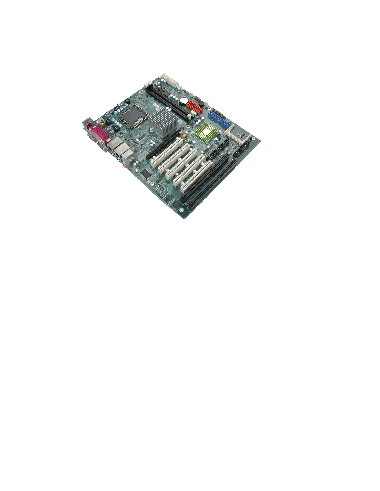
1.1 Introduction
MXGG Series
Figure 1-1: MXGG
The MXGG is an ATX motherboard with an 800/1066/1333 MHz front side bus. The
LGA775 socket accepts Intel® Core™2 Duo/Quad processors and the motherboard
supports two DDR3 DIMMs up to 4.0 GB each (8.0 GB total). The MXGG includes VGA
output with up to QXGA resolution. Multiple expansion cards may be added, including
PCIe x16, PCI and ISA interface. Other features include four SATA 3Gb/s, dual PCIe GbE,
digital I/O, five RS-232 serial ports, one RS-232/422/485 serial ports, one parallel port,
audio jacks and eight USB ports.
1.2 Benefits
Some of the MXGG motherboard benefits include:
Powerful graphics
Multiple LAN connections
Multiple expansion capabilities
1.3 Features
Some of the MXGG motherboard features are listed below:
CyberResearch, Inc. 15
25 Business Park Drive P: (203) 643-5000; F: (203) 643-5001
Branford, CT USA www.cyberresearch.com
Page 16

MXGG Series CyberResearch® Motherboards
ATX form factor
RoHS compliant
LGA775 CPU socket
Supports two DDR3 DIMMs
Supports dual display via VGA port and optional PCIe x16 SDVO expansion
card
T wo Gigabit Ethernet connectors
Four SATA connectors
Eight USB ports
Six serial ports
Supports PCI and ISA expansion cards with following combinations
o Five PCI cards and one ISA card
o Four PCI cards and two ISA cards
16 ©Copyright 2012 CyberResearch, Inc.
Page 17
®
CyberResearch
Motherboards
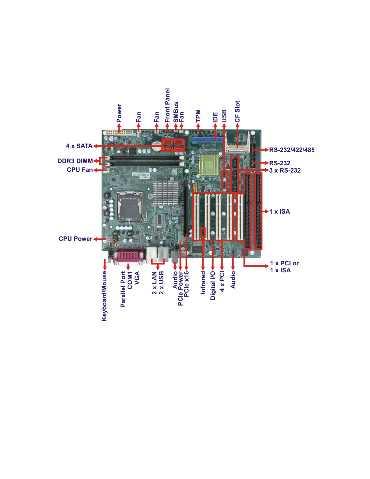
1.4 Connectors
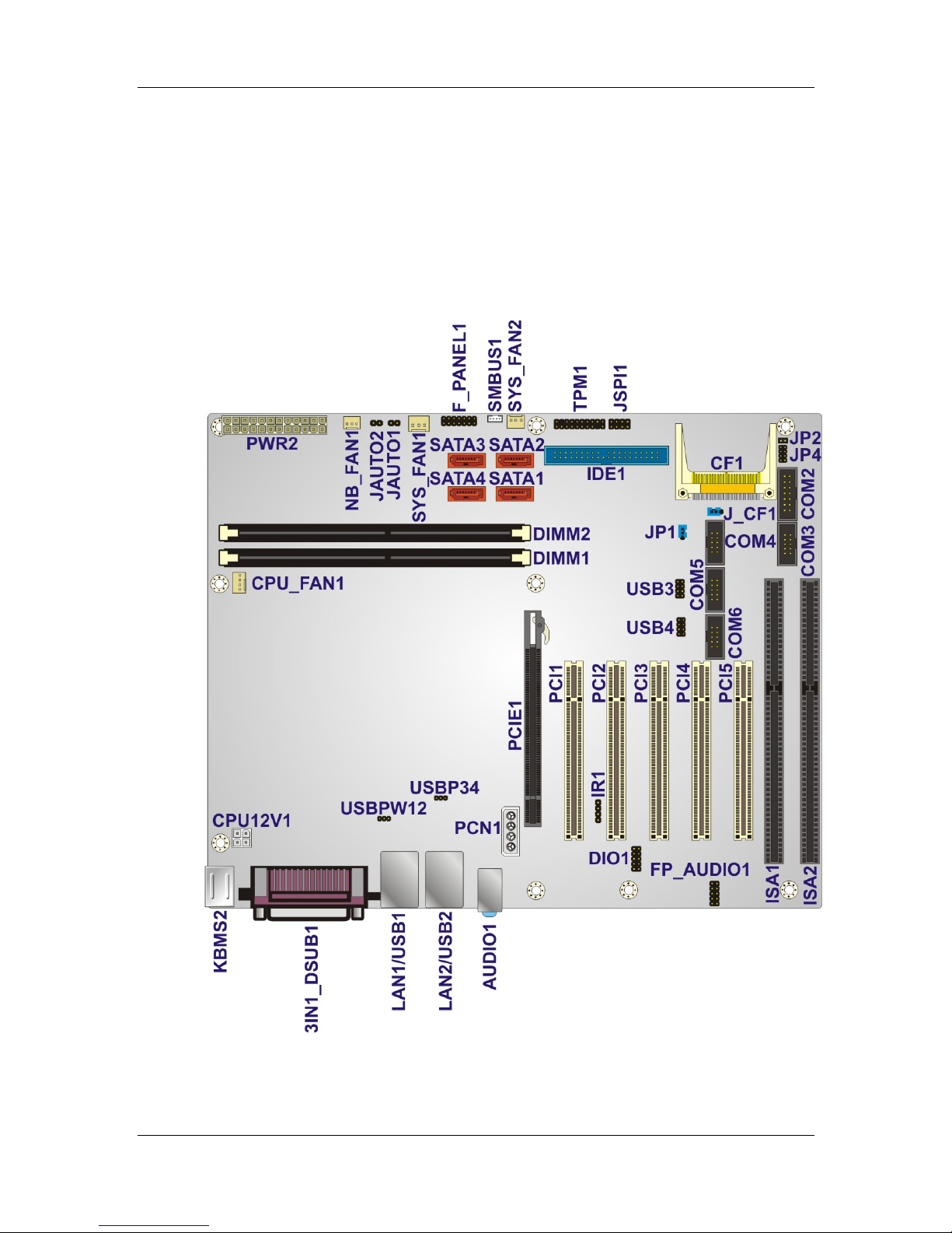
The connectors on the MXGG are shown in the figure below.
MXGG Series
Figure 1-2: Connectors
CyberResearch, Inc. 17
25 Business Park Drive P: (203) 643-5000; F: (203) 643-5001
Branford, CT USA www.cyberresearch.com
Page 18
MXGG Series CyberResearch® Motherboards
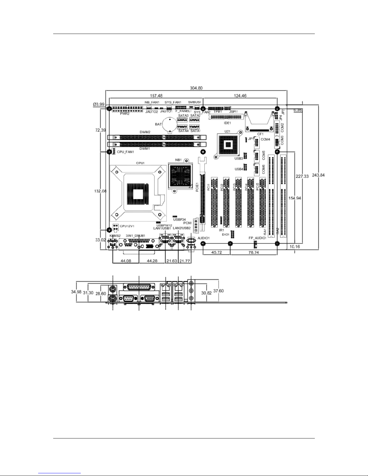
1.5 Dimensions
The main dimensions of the MXGG are shown in the diagram below.
Figure 1-3: Dimensions (mm)
18 ©Copyright 2012 CyberResearch, Inc.
Page 19
®
CyberResearch
Motherboards
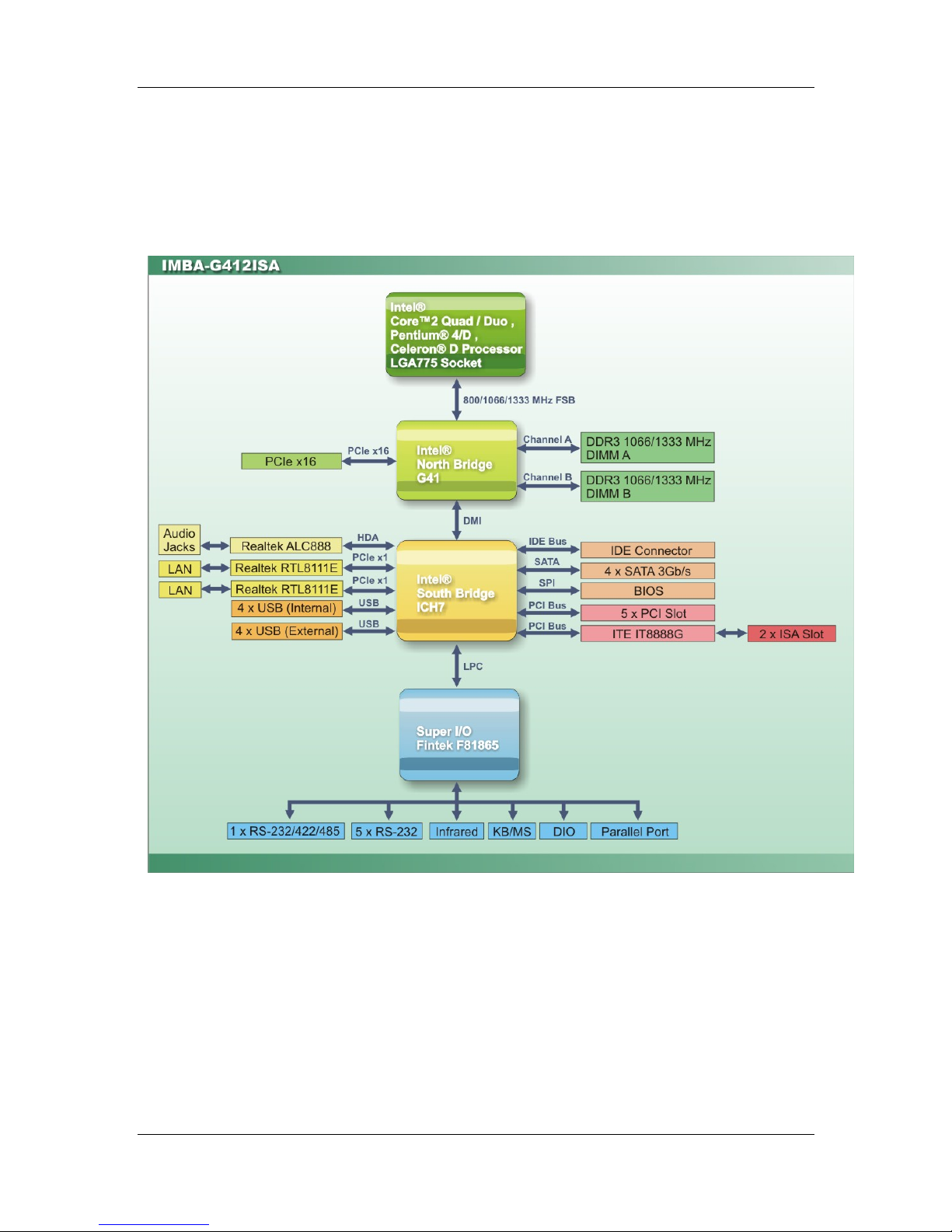
1.6 Data Flow
Figure 1-4 shows the data flow between the system chipset, the CPU and other
components installed on the motherboard.
MXGG Series
Figure 1-4: Data Flow Diagram
CyberResearch, Inc. 19
25 Business Park Drive P: (203) 643-5000; F: (203) 643-5001
Branford, CT USA www.cyberresearch.com
Page 20
MXGG Series CyberResearch® Motherboards
1.7 Technical Specifications
MXGG technical specifications are shown below.
Specifications MXGG
Form Factor
CPU Supported
Front Side Bus (FSB)
Northbridge Chipset
Memory
Graphic Engine
Integrated Graphics
Southbridge Chipset
BIOS
Digital I/O
Ethernet Controllers
ATX
Socket LGA775 Intel® Core™2 Duo/Quad, Pentium® D or
Celeron® processor
800/1066/1333 MHz
Intel® G41
Two 240-pin 800/1066 MHz dual-channel DDR3 SDRAM
DIMMs (system max. 4 GB)
Intel® GMA X4500
VGA integrated in Intel® G41 supports up to
2048 x 1536 @ 75 MHz
Intel® ICH7
UEFI BIOS
8-bit, 4-bit input/4-bit output
Two Realtek RTL8111E PCIe GbE controllers
(LAN1 with ASF2.0 support)
Audio
Super I/O Controller
Watchdog Timer
ISA Bridge
Expansion
Realtek ALC888 HD Audio codec
Fintek F81865
Software programmable supports 1~2 55 sec. system reset
ITE IT8888
One PCIe x16 socket
Four PCI sockets
One ISA socket
One PCI/ISA socket
20 ©Copyright 2012 CyberResearch, Inc.
Page 21
CyberResearch
I/O Interface
®
Motherboards
MXGG Series
Audio Jack
Fan connector
Keyboard/Mouse
Serial Ports
USB 2.0/1.1 ports
Infrared
Parallel Port
Serial ATA
One line-in
One line-out
One mic-in
One 4-pin wafer for CPU fan
Three 3-pin wafer for system fans
Two external PS/2 connectors
Five RS-232 COM connectors
One RS-232/422/485 COM connector
Four internal via pin header
Four external USB ports
One infrared connector via 5-pin header
One external parallel port
Four independent SATA channels with 3.0 Gb/s data
transfer rates
IDE
CompactFlash®
SMBus
TPM
One 40-pin IDE connector
One CF Type II slot
One 4-pin wafer SMBus connector
One TPM module connector via 20-pin header
Environmental and Power Specifications
Power Supply
Power Consumption
ATX power supported
5 V @ 5.06 A
12 V @ 2.01 A
3.3 V @ 0.15 A
-12 V @ 0.05 A
(2.8 GHz Intel® Core 2 Duo E7400 with two 1 GB
1066 MHz DDR3 DIMMs)
Operating temperature
Humidity
-10ºC ~ 60ºC, requires cooler and silicone heat sink paste
5% ~ 95% (non-condensing)
CyberResearch, Inc. 21
25 Business Park Drive P: (203) 643-5000; F: (203) 643-5001
Branford, CT USA www.cyberresearch.com
Page 22

MXGG Series CyberResearch® Motherboards
Physical Specifications
Dimensions
Weight (Gross/Net)
Table 1-1: Technical Specifications
305 mm x 244 mm
1200 g / 750 g
22 ©Copyright 2012 CyberResearch, Inc.
Page 23

CyberResearch
®
Motherboards
2 Packing List
MXGG Series
Chapter
2
CyberResearch, Inc. 23
25 Business Park Drive P: (203) 643-5000; F: (203) 643-5001
Branford, CT USA www.cyberresearch.com
Page 24

MXGG Series CyberResearch® Motherboards
2.1 Anti-static Precautions
WARNING!
Static electricity can destroy certain electronics. Make sure to follow the
ESD precautions to prevent damage to the product, and injury to the
user.
Make sure to adhere to the following guidelines:
Wear an anti-static wristband: We aring an anti-static wristband can prevent
electrostatic discharge.
Self-grounding: Touch a grounded conductor every few minutes to discharge
any excess static buildup.
Use an anti-static pad: When configuring any circuit board, place it on an
anti-static mat.
Only handle the edges of the PCB: Don't touch the surface of the
motherboard. Hold the motherboard by the edges when handling.
2.2 Unpacking Precautions
When the MXGG is unpacked, please do the following:
Follow the antistatic guidelines above.
Make sure the packing box is facing up wards when opening.
Make sure all the packing list items are present.
24 ©Copyright 2012 CyberResearch, Inc.
Page 25
®
CyberResearch
Motherboards
2.3 Packing List
NOTE:
If any of the components listed in the checklist below are missing, do
not proceed with the installation. Contact a CyberResearch sales
representative directly by sending an email to
sales@cyberresearch.com.
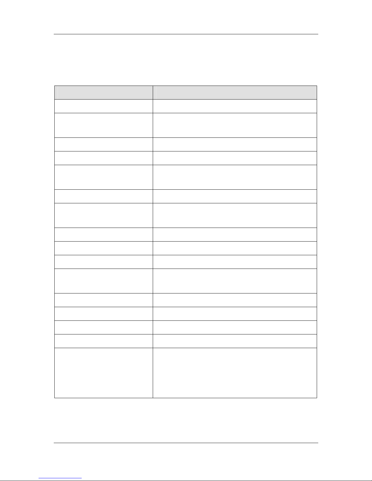
The MXGG is shipped with the following components:
Quantity Item and Part Number Image
1 MXGG Series
MXGG Series
4 SATA cable
1 Dual RS-232 cable
1 Mini jumper pack (2.54mm)
1 I/O shielding
CyberResearch, Inc. 25
25 Business Park Drive P: (203) 643-5000; F: (203) 643-5001
Branford, CT USA www.cyberresearch.com
Page 26
MXGG Series CyberResearch® Motherboards
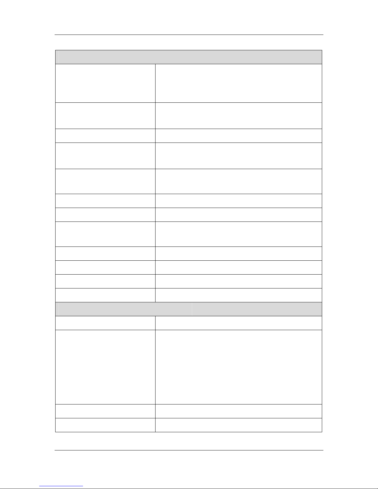
Quantity Item and Part Number Image
1 Utility DVD
1 Quick Installation Guide
Table 2-1: Packing List
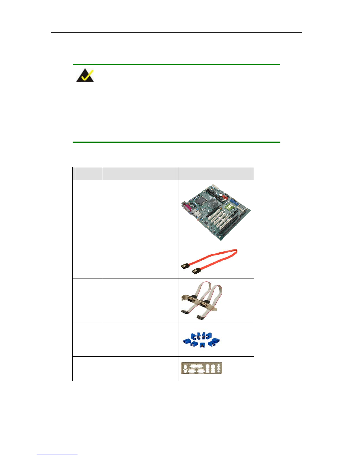
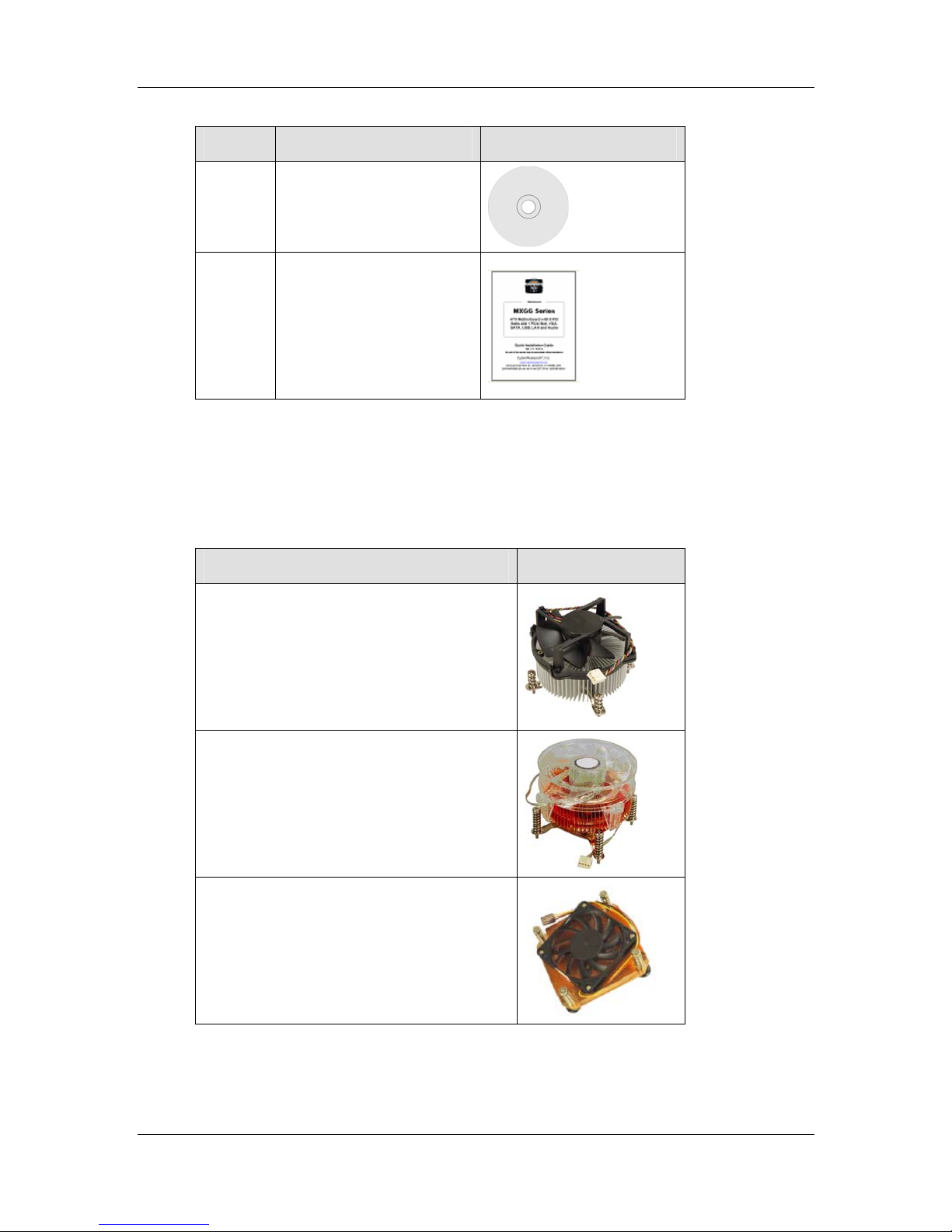
2.4 Optional Items
The following are optional components which may be separately purchased:
Item and Part Number Image
CPU cooler kit
CPU cooler kit
CPU cooler
26 ©Copyright 2012 CyberResearch, Inc.
Page 27
CyberResearch
Item and Part Number Image
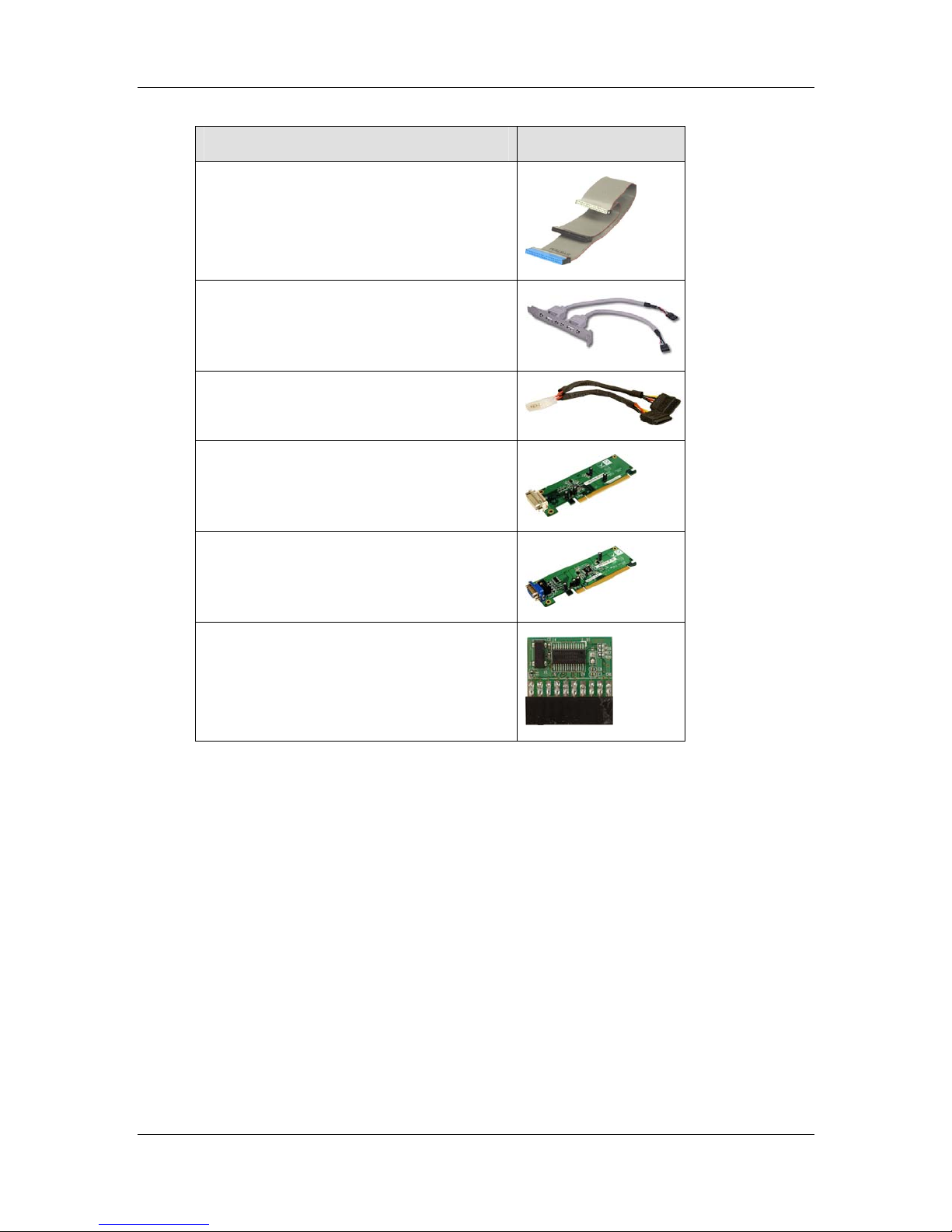
ATA 66/100 flat cable
USB cable
SATA power cable
DVI output SDVO card
®
Motherboards
MXGG Series
VGA output SDVO card
Infineon TPM module
Table 2-2: Optional Items
CyberResearch, Inc. 27
25 Business Park Drive P: (203) 643-5000; F: (203) 643-5001
Branford, CT USA www.cyberresearch.com
Page 28

MXGG Series CyberResearch® Motherboards
Chapter
3
3 Connectors
28 ©Copyright 2012 CyberResearch, Inc.
Page 29
CyberResearch
®
Motherboards
3.1 Peripheral Interface Connectors
This chapter details all the jumpers and connectors.
3.1.1 Layout
The figure below shows all the connectors and jumpers.
MXGG Series
Figure 3-1: Connectors and Jumpers
CyberResearch, Inc. 29
25 Business Park Drive P: (203) 643-5000; F: (203) 643-5001
Branford, CT USA www.cyberresearch.com
Page 30
MXGG Series CyberResearch® Motherboards
3.1.2 Peripheral Interface Connectors
The table below lists all the connectors on the board.
Connector Type Label
Audio connector 10-pin header FP_AUDIO1
Fan connector (CPU) 4-pin wafer CPU_FAN1
Fan connector (system) 3-pin wafer NB_FAN1,
SYS_FAN1,
SYS_FAN2
CompactFlash® slot CF Type II slot CF1
CPU power input connector 4-pin connector CPU12V1
Digital I/O connector 10-pin heade r DIO1
Front panel connector 14-pin header F_PANEL1
IDE connector 40-pin box header IDE1
Infrared connector 5-pin header IR1
ISA slots ISA slot ISA1, ISA2
Memory slot 240-pin DDR3 DIMM slot DIMM1, DIMM2
PCI slots PCI slot PCI1, PCI2,
PCI3, PCI4,
PCI5
PCIe x16 slot PCIe x16 slot PCIE1
PCIe power connector 4-pin connector PCN1
Power connector 24-pin connector PWR2
RS-232 serial port connector 10-pin box header COM3, COM4,
COM5, COM6
RS-232/422/485 serial port connector 14-pin box header COM2
SATA drive connectors 7-pin SATA drive connectors SATA1, SATA2,
SMBus connector 4-pin wafer SMBUS1
30 ©Copyright 2012 CyberResearch, Inc.
SATA3, SATA4
Page 31

CyberResearch
®
Motherboards
Connector Type Label
SPI Flash 8-pin header JSPI1
TPM connector 20-pin header TPM1
USB connectors 8-pin header USB3, USB4
Table 3–1: Internal Peripheral Connectors
3.1.3 External Interface Panel Connectors
The table below lists the connectors on the external I/O panel.
Connector Type Label
Audio connector Audio jack AUDIO1
Keyboard/Mouse connector PS/2 KBMS2
MXGG Series
LAN connector RJ-45 LAN1, LAN2
Parallel port DB-25 Female 3IN1_DSUB1A
Serial port connector DB-9 Male 3IN1_DSUB1B
USB connector USB port USB1, USB2
VGA connector 15-pin Female 3IN1_DSUB1C
Table 3–2: External Peripheral Connectors
3.2 Internal Peripheral Connectors
The section describes all of the connectors on the MXGG.
3.2.1 Audio Connector
CN Label: FP_AUDIO1
CN Type:
CN Location:
10-pin header
See
Figure 3-2
CN Pinouts:
This connector connects to speakers, a microphone and an audio input.
CyberResearch, Inc. 31
25 Business Park Drive P: (203) 643-5000; F: (203) 643-5001
Branford, CT USA www.cyberresearch.com
See
Table 3-3
Page 32

MXGG Series CyberResearch® Motherboards
Figure 3-2: Audio Connector Location
Pin Description Pin Description
1 MIC_L 2 Audio GND
3 MIC_R 4 FP_AUO_DETECT
5 LINE_R 6 PD
7 F_SENSE 8 NC
9 LINE_L 10 PD
Table 3-3: Audio Connector Pinouts
3.2.2 CPU Fan Connector
CN Label: CPU_FAN1
CN Type:
CN Location:
CN Pinouts:
The fan connector attaches to a CPU cooling fan.
4-pin wafer
See
Figure 3-3
See
Table 3-4
32 ©Copyright 2012 CyberResearch, Inc.
Page 33

CyberResearch
Figure 3-3: CPU Fan Connector Location
Pin Description
1 GND
2 +12 V
3 Fan In
®
Motherboards
MXGG Series
4 Fan Control
Table 3-4: CPU Fan Connector Pinouts
3.2.3 System Fan Connectors
CN Label: NB_FAN1, SYS_FAN1 and SYS_FAN2
CN Type:
CN Location:
CN Pinouts:
The fan connector attaches to a system cooling fan.
3-pin wafer
See
Figure 3-4
See
Table 3-5 and Table 3-6
Figure 3-4: System Fan Connector Locations
CyberResearch, Inc. 33
25 Business Park Drive P: (203) 643-5000; F: (203) 643-5001
Branford, CT USA www.cyberresearch.com
Page 34

MXGG Series CyberResearch® Motherboards
Pin Description
1 FANIN2
2 +12 V
3 GND
Table 3-5: System Fan Connector Pinouts (SYS_FAN1)
Pin Description
1 NC
2 +12 V
3 GND
Table 3-6: System Fan Connector Pinouts (SYS_FAN2 and SYS_FAN3)
3.2.4 CPU Power Input Connector
CN Label: CPU12V1
CN Type:
CN Location:
CN Pinouts:
4-pin connector
See
Figure 3-5
See
Table 3-7
The CPU power input connector provides power to the CPU.
Figure 3-5: CPU Power Input Connector Location
Pin Description
1 GND
2 GND
3 +12 V
4 +12 V
Table 3-7: CPU Power Input Connector Pinouts
34 ©Copyright 2012 CyberResearch, Inc.
Page 35

®
CyberResearch
Motherboards
3.2.5 Digital I/O Connector
CN Label: DIO1
MXGG Series
CN Type:
CN Location:
CN Pinouts:
10-pin header
See
Figure 3-6
See
Table 3-8
The digital I/O connector provides programmable input and output for external devices.
The digital I/O provides 4-bit output and 4-bit input.
Figure 3-6: Digital I/O Connector Location
Pin Description Pin Description
1 GND 2 VCC5S
3 Output 0 4 Output 1
5 Output 2 6 Output 3
7 Input 0 8 Input 1
9 Input 2 10 Input 3
Table 3-8: Digital I/O Connector Pinouts
3.2.6 Front Panel Connector
CN Label: F_PANEL1
CN Type:
CyberResearch, Inc. 35
25 Business Park Drive P: (203) 643-5000; F: (203) 643-5001
Branford, CT USA www.cyberresearch.com
14-pin header
Page 36

MXGG Series CyberResearch® Motherboards
See
See
Figure 3-7
Table 3-9
CN Location:
CN Pinouts:
The front panel connector connects to the indicator LEDs and buttons on the computer's
front panel.
Figure 3-7: Front Panel Connector Location
FUNCTION PIN DESCRIPTION FUNCTION PIN DESCRIPTION
Power LED
Power
Button
Table 3-9: Front Panel Connector Pinouts
3.2.7 IDE Connector
CN Label: IDE1
1 Power LED 2 BEEP_PWR
3 NC 4 NC
5 GND 6 NC
7 PWRBTSW#
9 GND
11 HDD LED+ 12 RESET HDD LED
13 HDD LED-
Buzzer
8 PC_BEEP
-- 10 NC
Reset
14 GND
CN Type:
CN Location:
CN Pinouts:
36 ©Copyright 2012 CyberResearch, Inc.
40-pin box header (2x20)
See
Figure 3-8
See
Table 3-10
Page 37

CyberResearch
The IDE connector can connect to an IDE hard drive or optical device.
Figure 3-8: IDE Connector Location
Pin Description Pin Description
1 RESET# 2 GROUND
3 DATA 7 4 DATA 8
®
Motherboards
MXGG Series
5 DATA 6 6 DATA 9
7 DATA 5 8 DATA 10
9 DATA 4 10 DATA 11
11 DATA 3 12 DATA 12
13 DATA 2 14 DATA 13
15 DATA 1 16 DATA 14
17 DATA 0 18 DATA 15
19 GROUND 20 N/C
21 IDE DRQ 22 GROUND
23 IOW# 24 GROUND
25 IOR# 26 GROUND
27 IDE CHRDY 28 GROUND
29 IDE DACK 30 GROUND–DEFAULT
31 INTERRUPT 32 N/C
33 SA1 34 N/C
35 SA0 36 SA2
37 HDC CS0# 38 HDC CS1#
39 HDD ACTIVE# 40 GROUND
Table 3-10: IDE Connector Pinouts
CyberResearch, Inc. 37
25 Business Park Drive P: (203) 643-5000; F: (203) 643-5001
Branford, CT USA www.cyberresearch.com
Page 38

MXGG Series CyberResearch® Motherboards
3.2.8 Infrared Interface Connector
CN Label: IR1
CN Type:
CN Location:
CN Pinouts:
5-pin header (1x5)
See
Figure 3-9
See
Table 3-11
The infrared connector attaches to an infrared receiver for use with remote controls.
Figure 3-9: Infrared Connector Location
Pin Description
1 +5V
2 NC
3 IR-RX
4 GND
5 IR-TX
Table 3-11: Infrared Connector Pinouts
3.2.9 Memory Slot
CN Label: DIMM1, DIMM2
CN Type:
CN Location:
DIMM slot
See
Figure 3-10
38 ©Copyright 2012 CyberResearch, Inc.
Page 39

CyberResearch
The DIMM slots are for DDR3 DIMM memory modules.
Figure 3-10: Memory Card Slot Location
®
Motherboards
MXGG Series
3.2.10 PCIe Power Input Connector
CN Label: PNC1
CN Type:
CN Location:
CN Pinouts:
The PCIe power input connector provides extra power to the PCIe card.
3-pin wafer (1x3)
See
Figure 3-11
See
Table 3-12
Figure 3-11: PCIe Power Input Connector Location
CyberResearch, Inc. 39
25 Business Park Drive P: (203) 643-5000; F: (203) 643-5001
Branford, CT USA www.cyberresearch.com
Page 40

MXGG Series CyberResearch® Motherboards
Pin Description
1 VCC +5 V
2 GND
3 GND
4 VCC +12 V
Table 3-12: PCIe Power Input Connector Pinouts
3.2.11 Power Connector
CN Label: PWR2
CN Type:
CN Location:
CN Pinouts:
24-pin connector
See
Figure 3-12
See
Table 3-13
The power connector connects to an ATX power supply.
Figure 3-12: Power Connector Location
Pin Description Pin Description
1 +3.3V 13 +3.3V
2 +3.3V 14 -12V
3 GND 15 GND
4 +5V 16 PS_ON5 GND 17 GND
6 +5V 18 GND
7 GND 19 GND
8 NC 20 NC
40 ©Copyright 2012 CyberResearch, Inc.
Page 41

CyberResearch
®
Motherboards
Pin Description Pin Description
9 +5V 21 +5V
10 +12V 22 +5V
11 +12V 23 +5V
12 +3.3V 24 GND
Table 3-13: Power Connector Pinouts
3.2.12 RS-232 Serial Port Connectors
CN Label: COM3, COM4, COM5, COM6
MXGG Series
CN Type:
CN Location:
CN Pinouts:
10-pin box header
See
Figure 3-13
See
Table 3-14
This connector provides RS-232 communications.
Figure 3-13: Serial Port Connector Locations
Pin Description
1 NRLSD
2 NDSR
3 NRX
4 NRTS
CyberResearch, Inc. 41
25 Business Park Drive P: (203) 643-5000; F: (203) 643-5001
Branford, CT USA www.cyberresearch.com
Page 42

MXGG Series CyberResearch® Motherboards
Pin Description
5 NTX
6 NCTS
7 NDTR
8 NRI
9 GND
10 NC
Table 3-14: Serial Port Connector Pinouts
3.2.13 RS-232/422/485 Serial Port Connector
CN Label: COM2
CN Type:
CN Location:
CN Pinouts:
14-pin box header
See
Figure 3-14
See
Table 3-15
This connector provides RS-232, RS-422 or RS-485 communi cations.
Figure 3-14: RS-232/422/485 Serial Port Connector Location
Pin Description Pin Description
1 NDDVD 2 NDSR
3 NRX 4 NRTS
5 NTX 6 NCTS
7 NDTR 8 NRI
9 GND 10 NC
42 ©Copyright 2012 CyberResearch, Inc.
Page 43

CyberResearch
®
Motherboards
Pin Description Pin Description
11 TX+ 12 TX13 RX+ 14 RX-
Table 3-15: RS-232/422/485 Serial Port Connector Pinouts
3.2.14 SATA Drive Connectors
CN Label: SATA1, SATA2, SATA3, SATA4
MXGG Series
CN Type:
CN Location:
7-pin SATA drive connectors
See
Figure 3-15
The SATA drive connectors can be connected to SATA 3Gb/s drives.
Figure 3-15: SATA Drive Connector Location
3.2.15 SMBus Connector
CN Label: SMBUS1
CN Type:
CN Location:
CN Pinouts:
The SMBus (System Management Bus) connector provides low-speed system
management communications.
CyberResearch, Inc. 43
25 Business Park Drive P: (203) 643-5000; F: (203) 643-5001
Branford, CT USA www.cyberresearch.com
4-pin wafer
See
Figure 3-16
See
Table 3-16
Page 44

MXGG Series CyberResearch® Motherboards
Figure 3-16: SMBus Connector Locations
Pin Description
1 GND
2 SMBDATA
3 SMBCLK
4 +5V
Table 3-16: SMBus Connector Pinouts
3.2.16 SPI Flash Connector
CN Label: JSPI1
CN Type:
CN Location:
CN Pinouts:
The 8-pin SPI Flash connector is used to flash the BIOS.
8-pin header
See
Figure 3-17
See
Table 3-17
44 ©Copyright 2012 CyberResearch, Inc.
Page 45

CyberResearch
Figure 3-17: SPI Flash Connector
Pin Description Pin Description
1 +3.3V 2 GND
3 CS# 4 CLOCK
5 SO 6 SI
®
Motherboards
MXGG Series
7 NC 8 NC
Table 3-17: SPI Flash Connector
3.2.17 TPM Connector
CN Label: TPM1
CN Type:
CN Location:
CN Pinouts:
The Trusted Platform Module (TPM) connector secures the system on bootup.
20-pin header (2x10)
See
Figure 3-18
See
Table 3-18
CyberResearch, Inc. 45
25 Business Park Drive P: (203) 643-5000; F: (203) 643-5001
Branford, CT USA www.cyberresearch.com
Page 46

MXGG Series CyberResearch® Motherboards
Figure 3-18: TPM Connector Pinout Location
Pin Description Pin Description
1 TPMCLK 2 GND
3 LFRAME- 4 NC
5 PCIRST4- 6 +5 V
7 LAD3 8 LAD2
9 LAD0 10 LAD1
11 GND 12 GND
13 SMBCLK_MAIN 14 SMBDATA_MAIN
15 +3.3 V 16 SERIRQ
17 GND 18 CLKRUN19 +3.3 V 20 LDRQ-
Table 3-18: TPM Connector Pinouts
3.2.18 USB Connectors
CN Label: USB3, USB4
CN Type:
CN Location:
CN Pinouts:
8-pin header
See
Figure 3-19
See
Table 3-19
The USB connectors connect to USB devices. Each pin header provides two USB ports.
46 ©Copyright 2012 CyberResearch, Inc.
Page 47

CyberResearch
Figure 3-19: USB Connector Pinout Locations
Pin Description Pin Description
1 +5V 2 GND
3 USBP4/6# 4 USBP5/7
®
Motherboards
MXGG Series
5 USBP4/6 6 USBP5/7#
7 GND 8 +5V
Table 3-19: USB Port Connector Pinouts
3.3 External Peripheral Interface Connector Panel
The figure below shows the external peripheral interface connector (EPIC) panel. The
EPIC panel consists of the following:
Figure 3-20: External Peripheral Interface Connector
CyberResearch, Inc. 47
25 Business Park Drive P: (203) 643-5000; F: (203) 643-5001
Branford, CT USA www.cyberresearch.com
Page 48

MXGG Series CyberResearch® Motherboards
3.3.1 Audio Connectors
CN Label: AUDIO1
CN Type:
CN Location:
Audio jacks
See
Figure 3-20
The audio jacks connect to external audio devices.
Line In port (Light Blue): Connects a DVD-ROM, DV D player, or other audio
devices.
Line Out port (Lime): Connects to a he adphone or a speaker. With
multi-channel configurations, this port can also connect to front speakers.
Microphone (Pink): Connects a microphone.
Figure 3-21: Audio Connector
3.3.2 Keyboard/Mouse Connector
CN Label: KBMS2
CN Type:
CN Location:
CN Pinouts:
The keyboard and mouse connector is a standard PS/2 connector.
48 ©Copyright 2012 CyberResearch, Inc.
PS/2
See
Figure 3-20
See Table 3-20, Figure 3-22
Page 49

CyberResearch
Figure 3-22: PS/2 Pinout and Configuration
®
Motherboards
MXGG Series
Pin Description Pin Description
1 KB_DATA 8 NC
2 NC 9 GND
3 GND 10 5 V
4 5 V 11 MS_CLK
5 KB_CLK 12 NC
6 NC 13 KB_GND
7 MS_DATA 14 KB_GND
Table 3-20: Keyboard Connector Pinouts
3.3.3 LAN Connectors
CN Label: LAN1, LAN2
CN Type:
CN Location:
CN Pinouts:
RJ-45
See
Figure 3-20
See Table 3-21
The LAN connector connects to a local network.
CyberResearch, Inc. 49
25 Business Park Drive P: (203) 643-5000; F: (203) 643-5001
Branford, CT USA www.cyberresearch.com
Page 50

MXGG Series CyberResearch® Motherboards
Pin Description Pin Description
1 3.3 V 8 LAN1/2_MDI3+
2 LAN1/2_MDI0+ 9 LAN1/2_MDI33 LAN1/2_MDI0- 10 GND
4 LAN1/2_MDI1+ 11 LAN1/2_LINK100
5 LAN1/2_MDI1- 12 LAN1/2_LINK1000
6 LAN1/2_MDI2+ 13 LAN1/2_LED0
7 LAN1/2_MDI2- 14 3.3 V
Table 3-21: LAN Pinouts
3.3.4 Parallel Port Connector
CN Label: 3IN1_DSUB1A
CN Type:
CN Location:
CN Pinouts:
DB-25 Female
See
Figure 3-20
See Table 3-22
The parallel port connects to parallel port device, typically a printer.
Pin Description Pin Description
1 STROBE# 14 AUTO FORM FEED #
2 DATA 0 15 ERROR#
3 DATA 1 16 INITIALIZE
4 DATA 2 17 PRINTER SELECT LN#
5 DATA 3 18 GROUND
6 DATA 4 19 GROUND
7 DATA 5 20 GROUND
8 DATA 6 21 GROUND
9 DATA 7 22 GROUND
10 ACKNOWLEDGE 23 GROUND
11 BUSY 24 GROUND
12 PAPER EMPTY 25 GROUND
50 ©Copyright 2012 CyberResearch, Inc.
Page 51

CyberResearch
®
Motherboards
Pin Description Pin Description
13 PRINTER SELECT
Table 3-22: Parallel Port Connector Pinouts
Figure 3-23: Parallel Port Connector Location
3.3.5 Serial Port Connector (COM1)
CN Label: 3IN1_DSUB1B (COM1)
MXGG Series
CN Type:
CN Location:
CN Pinouts:
DB-9 Male
See
Figure 3-20
See
Table 3-23 and Figure 3-24
The serial port connects to a RS-232 serial communications device.
Pin Description Pin Description
1 DDVD 6 DSR
2 RX 7 RTS
3 TX 8 CTS
4 DTR 9 RI
5 GND
Table 3-23: Serial Port Pinouts
CyberResearch, Inc. 51
25 Business Park Drive P: (203) 643-5000; F: (203) 643-5001
Branford, CT USA www.cyberresearch.com
Page 52

MXGG Series CyberResearch® Motherboards
Figure 3-24: Serial Port Pinouts
3.3.6 USB Connectors
CN Label: USB1, USB2
CN Type:
CN Location:
CN Pinouts:
USB port
See
Figure 3-20
See
Table 3-24
The USB connector can be connected to a USB device.
Pin Description Pin Description
1 USBPWR1 2 USBP0/23 USBP0/2+ 4 GND
5 USBPWR1 6 USBP1/37 USBP1/3+ 8 GND
Table 3-24: USB Port Pinouts
3.3.7 VGA Connector
CN Label: 3IN1_DSUB1C
CN Type:
CN Location:
CN Pinouts:
The VGA connector connects to a monitor that accepts a standard VGA input.
52 ©Copyright 2012 CyberResearch, Inc.
15-pin Female
See
Figure 3-20
See Figure 3-25 and Table 3-25
Page 53

CyberResearch
Figure 3-25: VGA Connector
Pin Description Pin Description
1 RED 2 GREEN
3 BLUE 4 CRT_PLUG#
5 GND 6 GND
7 GND 8 GND
9 VGAVCC 10 GND
®
Motherboards
MXGG Series
11 NC 12 DDC DAT
13 HSYNC 14 VSYNC
15 DDCCLK
Table 3-25: VGA Connector Pinouts
CyberResearch, Inc. 53
25 Business Park Drive P: (203) 643-5000; F: (203) 643-5001
Branford, CT USA www.cyberresearch.com
Page 54

MXGG Series CyberResearch® Motherboards
Chapter
4
4 Installation
54 ©Copyright 2012 CyberResearch, Inc.
Page 55

CyberResearch
®
Motherboards
4.1 Anti-static Precautions
WARNING:
Failure to take ESD precautions during the installation of the MXGG
may result in permanent damage to the MXGG and severe injury to the
user.
Electrostatic discharge (ESD) can cause serious damage to electronic components,
including the MXGG. Dry climates are especially susceptible to ESD. It is therefore critical
that whenever the MXGG or any other electrical component is handled, the following
anti-static precautions are strictly adhered to.
MXGG Series
Wear an anti-static wristband: We aring a simple anti-static wristband can
help to prevent ESD from damaging the board.
Self-grounding: Before handling the board, touch any grounded conducting
material. During the time the board is handled, frequently touch any
conducting materials that are connected to the ground.
Use an anti-static pad: When configuring the MXGG, place it on an
antic-static pad. This reduces the possibility of ESD damaging the MXGG.
Only handle the edges of the PCB: When handling the PCB, hold the PCB
by the edges.
4.2 Installation Considerations
NOTE:
The following installation notices and installation considerations should
be read and understood before installation. All installation notices must
be strictly adhered to. Failing to adhere to these precautions may lead
to severe damage and injury to the person performing the installation.
CyberResearch, Inc. 55
25 Business Park Drive P: (203) 643-5000; F: (203) 643-5001
Branford, CT USA www.cyberresearch.com
Page 56

MXGG Series CyberResearch® Motherboards
WARNING:
The installation instructions described in this manual should be
carefully followed in order to prevent damage to the components and
injury to the user.
Before and during the installation please DO the following:
Read the user manual:
o The user manual provides a complete description of the MXGG
installation instructions and configuration options.
Wear an electrostatic discharge cuff (ESD):
o Electronic components are easily damaged by ESD. Wearing an ESD cuff
removes ESD from the body and helps prevent ESD damage.
Place the MXGG on an antistatic pad:
o When installing or configuring the motherboard, place it on an antistatic
pad. This helps to prevent potential ESD damage.
Turn all power to the MXGG off:
o When working with the MXGG, make sure that it is disconnected from all
power supplies and that no electricity is being fed into the system.
Before and during the installation of the MXGG DO NOT:
Remove any of the stickers on the PCB board. These stickers are required for
warranty validation.
Use the product before verifying all the cables and power connectors are
properly connected.
Allow screws to come in contact with the PCB circuit, connector pins, or its
components.
56 ©Copyright 2012 CyberResearch, Inc.
Page 57

®
CyberResearch
Motherboards
4.3 Basic Installation
This section outlines the parts that must be installed for the system to function correctly.
4.3.1 CPU Installation
NOTE:
To enable Hyper-Threading, the CPU and chipset must both support it.
WARNING:
CPUs are expensive and sensitive components. When installing the
MXGG Series
CPU please be careful not to damage it in anyway. Make sure the CPU
is installed properly and ensure the correct cooling kit is properly
installed.
The LGA775 socket is shown in Figure 4-1.
Figure 4-1: Intel LGA775 Socket
To install the CPU, follow the steps below.
CyberResearch, Inc. 57
25 Business Park Drive P: (203) 643-5000; F: (203) 643-5001
Branford, CT USA www.cyberresearch.com
Page 58

MXGG Series CyberResearch® Motherboards
WARNING:
DO NOT touch the pins at the bottom of the CPU. When handling the
CPU, only hold it on the sides.
Step 1: Remove the protective cover. The black protective cover can be removed by
pulling up on the tab labeled "Remove". See
Figure 4-2.
Figure 4-2: Remove Protective Cover
Step 2: Open the socket. Disengage the load lever by pressing the lever down and
slightly outward to clear the retention tab. Fully open the lever, then open the
load plate. See
Figure 4-3.
Figure 4-3: CPU Socket Load Plate
58 ©Copyright 2012 CyberResearch, Inc.
Page 59

CyberResearch
Step 3: Inspect the CPU socket. Make sure there are no bent pins and make sure the
Step 4: Orientate the CPU properly. The contact array should be facing the CPU
Step 5: Correctly position the CPU. Match the Pin 1 mark with the cut edge on the
Step 6: Align the CPU pins. Locate pin 1 and the two orientation notches on the CPU.
Step 7: Insert the CPU. Gently insert the CPU into the socket. If the CPU pins are
®
Motherboards
MXGG Series
socket contacts are free of foreign material. If any debris is found, remove it with
compressed air.
socket.
CPU socket.
Carefully match the two orientation notches on the CPU with the socket
alignment keys.
properly aligned, the CPU should slide into the CPU socket smoothly. See
Figure 4-4.
Figure 4-4: Insert the Socket LGA775 CPU
Step 8: Close the CPU socket. Close the load plate and engage the load lever by
pushing it back to its original position. There will be some resist ance, but will not
require extreme pressure.
Step 9: Connect the 12 V power to the board. Connect the 12 V power from the power
supply to the board. Step 0:
CyberResearch, Inc. 59
25 Business Park Drive P: (203) 643-5000; F: (203) 643-5001
Branford, CT USA www.cyberresearch.com
Page 60

MXGG Series CyberResearch® Motherboards
4.3.2 Cooling Kit Installation
WARNING:
DO NOT use the original Intel® heat sink and fan. A proprietary one is
recommended.
Figure 4-5: Cooling Kits
The cooling kit can be purchased from CyberResearch, Inc.; cooling kits include a
heatsink and fan.
WARNING:
Do not wipe off (accidentally or otherwise) the pre-sprayed layer of
thermal paste on the bottom of the heat sink. The thermal paste
between the CPU and the heat sink is important for optimum heat
dissipation.
To install the cooling kit, follow the instructions below.
Step 1: Place the cooling kit onto the socket LGA775 CPU. Make sure the CPU
cable can be properly routed when the cooling kit is installed.
Step 2: Properly align the cooling kit. Make sure the four spring screw fasteners can
pass through the pre-drilled holes on the PCB.
60 ©Copyright 2012 CyberResearch, Inc.
Page 61

CyberResearch
Step 3: Mount the cooling kit. Gently place the cooling kit on top of the CPU. Make
Step 4: Secure the cooling kit. From the solder side of the PCB, align the support
®
Motherboards
MXGG Series
sure the four threaded screws on the corners of the cooling kit properly pass
through the predrilled holes on the bottom of the PCB.
bracket to the screw threads on heat sink that were inserted through the PCB
holes. (See
Figure 4-6)
Figure 4-6: Securing the Heat sink to the MXGG
Step 5: Tighten the screws. Use a screwdriver to tighten the four screws. Tighten each
nut a few turns at a time and do not over-tighten the screws.
Step 6: Connect the fan cable. Connect the cooling kit fan cable to the fan connector
on the MXGG. Carefully route the cable and avoid heat generating chips and fan
blades. Step 0:
CyberResearch, Inc. 61
25 Business Park Drive P: (203) 643-5000; F: (203) 643-5001
Branford, CT USA www.cyberresearch.com
Page 62

MXGG Series CyberResearch® Motherboards
4.3.3 DIMM Installation
To install a DIMM, please follow the steps below and refer to Figure 4-7.
Figure 4-7: DIMM Installation
Step 1: Open the DIMM socket handles. Open the two handles outwards as far as they
possible. See
Figure 4-7.
Step 2: Align the DIMM with the socket. Align the DIMM so the notch lin es up with the
notch on the memory socket. See
Figure 4-7.
Step 3: Insert the DIMM. Once aligned, press down until the DIMM is properly seated.
Clip the two handles into place. See
Figure 4-7.
Step 4: Removing a DIMM. To remove a DIMM, push both handles outward. The
memory module is ejected.Step 0:
4.3.4 Motherboard Installation
To install the MXGG motherboard into the chassis please refer to the reference material
that came with the chassis.
62 ©Copyright 2012 CyberResearch, Inc.
Page 63

®
CyberResearch
Motherboards
4.4 Jumper Settings
NOTE:
A jumper is a metal bridge used to close
an electrical circuit. It consists of two or
three metal pins and a small metal clip
(often protected by a plastic cover) that
slides over the pins to connect them. To
CLOSE/SHORT a jumper means
connecting the pins of the jumper with
the plastic clip and to OPEN a jumper means removing the plastic clip
from a jumper.
MXGG Series
The MXGG includes some jumpers shown in Table 4-1.
Description Label Type
AT/ATX power select jumpers JAUTO1,
2-pin header
JAUTO2
Clear CMOS jumper JP1 3-pin header
COM2 function select jumper JP4 6-pin header
CompactFlash® setup JP2 2-pin header
CF voltage select jumper J_CF1 3-pin header
USB power select jumpers USBPW12,
3-pin header
USBP34
Table 4-1: Jumpers
4.4.1 AT/ATX Power Select Jumpers
Jumper Label: JAUTO1, JAUTO2
Jumper Type:
Jumper Settings:
CyberResearch, Inc. 63
25 Business Park Drive P: (203) 643-5000; F: (203) 643-5001
Branford, CT USA www.cyberresearch.com
2-pin header
See
Table 4-2
Page 64

MXGG Series CyberResearch® Motherboards
See
Jumper Location:
Figure 4-8
The AT Power Select jumper specifies the systems power mode as AT or ATX.
Setting Description
Open Use ATX power (Default)
Short Use AT power
Table 4-2: AT/ATX Power Select Jumper Settings
Figure 4-8: AT/ATX Power Select Jumper Location
4.4.2 Clear CMOS Jumper
Jumper Label: JP1
Jumper Type:
Jumper Settings:
Jumper Location:
3-pin header
See
Table 4-3
See
Figure 4-9
To reset the BIOS, move the jumper to the "Clear BIOS" position for 3 seconds or more,
and then move back to the default position.
Pin Description
Short 1-2 Normal (Default)
Short 2-3 Clear BIOS
Table 4-3: Clear BIOS Jumper Settings
64 ©Copyright 2012 CyberResearch, Inc.
Page 65

CyberResearch
®
Motherboards
Figure 4-9: Clear BIOS Jumper Location
4.4.3 COM 2 Function Select Jumper
Jumper Label: JP4
MXGG Series
Jumper Type:
Jumper Settings:
Jumper Location:
6-pin header
See
Table 4-4
See
Figure 4-10
The COM 2 Function Select jumper sets the communication protocol used by the second
serial communications port (COM 2) as RS-232, RS-422 or RS -485. The COM 2 Function
Select settings are shown in
Setting Description
Short 1-2 RS-232 (Default)
Short 3-4 RS-422
Short 5-6 RS-485
Table 4-4.
Table 4-4: COM 2 Function Select Jumper Settings
Figure 4-10: COM 2 Function Select Jumper Location
CyberResearch, Inc. 65
25 Business Park Drive P: (203) 643-5000; F: (203) 643-5001
Branford, CT USA www.cyberresearch.com
Page 66

MXGG Series CyberResearch® Motherboards
4.4.4 CompactFlash® Setup
Jumper Label: JP2
Jumper Type:
Jumper Settings:
Jumper Location:
2-pin header
See
Table 4-5
See
Figure 4-11
The CompactFlash® slot is connected through an IDE connection. This jumper sets the
CompactFlash® card as the master or slave IDE device.
Setting Description
Short Master (Default)
Open Slave
Table 4-5: CompactFlash® Setup Jumper Settings
Figure 4-11: CompactFlash® Setup Jumper Location
4.4.5 CF Voltage Select Jumper
Jumper Label: J_CF1
Jumper Type:
Jumper Settings:
Jumper Location:
The CF voltage select jumper sets the voltage of the CompactFlash® slot.
66 ©Copyright 2012 CyberResearch, Inc.
3-pin header
See
Table 4-6
See
Figure 4-12
Page 67

CyberResearch
Setting Description
Short 1-2 +5.0 V
Short 2-3 +3.3 V
®
Motherboards
MXGG Series
Table 4-6: LDVD Voltage Selection Jumper Settings
Figure 4-12: LDVD Voltage Selection Jumper Location
4.4.6 USB Power Select Jumpers
Jumper Label: USBPW12, USBP34
Jumper Type:
3-pin header
See
Jumper Settings:
Jumper Location:
Table 4-7
See
Figure 4-13
The USB Power Select jumper specifies the USB power.
Setting Description
Short 1-2 +5 V (Default)
Short 2-3 +5VSB
Table 4-7: USB Power Select Jumper Settings
CyberResearch, Inc. 67
25 Business Park Drive P: (203) 643-5000; F: (203) 643-5001
Branford, CT USA www.cyberresearch.com
Page 68

MXGG Series CyberResearch® Motherboards
Figure 4-13: USB Power Select Jumper Location
4.5 Internal Peripheral Device Connections
This section outlines the installation of peripheral devices to the onboard connectors.
4.5.1 SATA Drive Connection
The MXGG is shipped with two SATA drive cables and one SATA drive power cable. To
connect the SATA drives to the connectors, please follow the steps below.
Step 1: Locate the connectors.
Step 2: Insert the cable connector. Press the clip on the connector at the end of the
SATA cable and insert the cable connector into the on-board SATA drive
connector. See
Figure 4-14.
68 ©Copyright 2012 CyberResearch, Inc.
Page 69

CyberResearch
®
Motherboards
MXGG Series
Figure 4-14: SATA Drive Cable Connection
Step 3: Connect the cable to the SATA disk. Connect the connector on the other end
of the cable to the connector at the back of the SATA drive. See
Figure 4-15.
Step 4: Connect the SATA power cable. Connect the SATA power connector to the
back of the SATA drive. See
Figure 4-15. =
CyberResearch, Inc. 69
25 Business Park Drive P: (203) 643-5000; F: (203) 643-5001
Branford, CT USA www.cyberresearch.com
Page 70

MXGG Series CyberResearch® Motherboards
Figure 4-15: SATA Power Drive Connection
4.5.2 Dual RS-232 Cable with Slot Bracket
The dual RS-232 cable slot connector consists of two connectors attached to two
independent cables. Each cable is then attached to a D-sub 9 male connector that is
mounted onto a slot. To install the dual RS-232 cable, please follow the steps below.
Step 1: Locate the connectors. The locations of the RS-232 connectors are shown in
Chapter 3.
Step 2: Insert the cable connectors. Insert one connector into each serial port box
headers. See
Figure 4-16. A key on the front of the cable connectors ensures
the connector can only be installed in one direction.
Figure 4-16: Dual RS-232 Cable Installation
70 ©Copyright 2012 CyberResearch, Inc.
Page 71

CyberResearch
®
Motherboards
Step 3: Secure the bracket. The dual RS-232 connector has two D-sub 9 male
connectors secured on a bracket. To secure the bracket to the chassis please
refer to the reference material that came with the chassis. Step 0:
4.6 External Peripheral Interface Connection
This section describes connecting devices to the external connectors on the MXGG.
4.6.1 Audio Connector
The audio jacks on the external audio connector enable the MXGG to be connected to a
stereo sound setup. To install the audio devices, follow the steps below.
Step 1: Identify the audio jacks. The jacks on your home theater system or speakers
may not match the colors on the rear panel. Please review the connection
MXGG Series
options carefully.
Step 2: Plug the audio cables into the audio jacks. Plug the audio cables into the
audio jacks. If the plugs on your speakers are different, an adapter will need to
be used to plug them into the audio jacks.
Line In port (Light Blue): Connects a DVD-ROM, DV D player, or other audio
devices.
Line Out port (Lime): Connects to a he adphone or a speaker.
Microphone (Pink): Connects to a microphone.
CyberResearch, Inc. 71
25 Business Park Drive P: (203) 643-5000; F: (203) 643-5001
Branford, CT USA www.cyberresearch.com
Page 72

MXGG Series CyberResearch® Motherboards
Figure 4-17: Audio Connector
Step 3: Check audio clarity. Check that the sound is coming through the right speakers
by adjusting the balance front to rear and left to right. Step 0:
4.6.2 PS/2 Keyboard and Mouse Connection
The MXGG has a dual PS/2 connector on the external peripheral interface panel. The dual
PS/2 connector is used to connect to a keyboard and mouse to the system. Follow the
steps below to connect a keyboard and mouse to the MXGG.
Step 1: Locate the dual PS/2 connector. The location of the dual PS/2 connector is
shown in Chapter 3.
Step 2: Insert the keyboard/mouse connector. Insert a PS/2 keyboard or mouse
connector into the appropriate PS/2 connector on the external peripheral
interface connector . See
Figure 4-18.
72 ©Copyright 2012 CyberResearch, Inc.
Page 73

CyberResearch
®
Motherboards
MXGG Series
Figure 4-18: PS/2 Keyboard/Mouse Connector
4.6.3 LAN Connection
There are two external RJ-45 LAN connectors. The RJ-45 connectors enable connection
to an external network. To connect a LAN cable with an RJ-45 connector, please follow
the instructions below.
Step 1: Locate the RJ-45 connectors. The locations of the USB connectors are shown
in Chapter 4.
Step 2: Align the connectors. Align the RJ-45 connector on the LAN cable with one of
the RJ-45 connectors on the MXGG. See
Figure 4-19.
CyberResearch, Inc. 73
25 Business Park Drive P: (203) 643-5000; F: (203) 643-5001
Branford, CT USA www.cyberresearch.com
Page 74

MXGG Series CyberResearch® Motherboards
Figure 4-19: LAN Connection
Step 3: Insert the LAN cable RJ-45 connector. Once ali gned, gently insert the LAN
cable RJ-45 connector into the on-board RJ-45 connector. Step 0:
4.6.4 Parallel Device Connection
The MXGG has a single female DB-25 connector on the external peripheral interface
panel for parallel devices. Follow the steps below to connect a parallel device to the
MXGG.
Step 1: Locate the DB-25 connector. The location of the DB-25 connector is shown in
Chapter 3.
Step 2: Insert the DB-25 connector. Insert the DB-25 connector of a parallel device
into the DB-25 connector on the external peripheral interface. See
Figure 4-20.
74 ©Copyright 2012 CyberResearch, Inc.
Page 75

CyberResearch
®
Motherboards
MXGG Series
Figure 4-20: Parallel Device Connector
Step 3: Secure the connector. Secure the DB-25 connector to the external interface by
tightening the two retention screws on either side of the connector.
4.6.5 Serial Device Connection
The MXGG has one male DB-9 connectors on the external peripheral interface panel for a
serial device. Follow the steps below to connect a serial device to the MXGG.
Step 1: Locate the DB-9 connector. The location of the DB-9 connector is shown in
Chapter 3.
Step 2: Insert the serial connector. Insert the DB-9 connector of a serial device into
the DB-9 connector on the external peripheral interface. See
Figure 4-21.
CyberResearch, Inc. 75
25 Business Park Drive P: (203) 643-5000; F: (203) 643-5001
Branford, CT USA www.cyberresearch.com
Page 76

MXGG Series CyberResearch® Motherboards
Figure 4-21: Serial Device Connector
Step 3: Secure the connector. Secure the serial device connector to the external
interface by tightening the two retention screws on either side of the connector.
4.6.6 USB Device Connection
The external USB Series "A" receptacle connectors provide easier and quicker access to
external USB devices. Follow the steps below to connect USB devices to the MXGG.
Step 1: Locate the USB Series "A" receptacle connectors. The location of the USB
Series "A" receptacle connectors are shown in Chapter 3.
Step 2: Insert a USB Series "A" plug. Insert the USB Series "A" plug of a device into
the USB Series "A" receptacle on the external peripheral interface. See
Figure 4-22.
Step 0:
76 ©Copyright 2012 CyberResearch, Inc.
Page 77

CyberResearch
®
Motherboards
MXGG Series
Figure 4-22: USB Connector
4.6.7 VGA Monitor Connection
The MXGG has a single female DB-15 connector on the external peripheral interface
panel. The DB-15 connector is connected to a CRT or VGA monitor. To connect a monitor
to the MXGG, please follow the instructions below.
Step 1: Locate the female DB-15 connector. The location of the female DB-15
connector is shown in Chapter 3.
Step 2: Align the VGA connector. Align the male DB-15 connector on the VGA screen
cable with the female DB-15 connector on the external peripheral interface.
Step 3: Insert the VGA connector. Once the connectors are properly aligned with the
insert the male connector from the VGA screen into the female connector on the
MXGG. See
Figure 4-23.
CyberResearch, Inc. 77
25 Business Park Drive P: (203) 643-5000; F: (203) 643-5001
Branford, CT USA www.cyberresearch.com
Page 78

MXGG Series CyberResearch® Motherboards
Figure 4-23: VGA Connector
Step 4: Secure the connector. Secure the DB-15 VGA connector from the VGA
monitor to the external interface by tightening the two retention screws on either
side of the connector. Step 0:
4.7 Software Installation
All the drivers for the MXGG are on the DVD that came with the system. To install the
drivers, please follow the steps below.
Step 1: Insert the DVD into a DVD drive connected to the system.
NOTE:
If the installation program doesn't start automatically:
Click "Start->My Computer->DVD Drive->autorun.exe"
Step 2: The driver main menu appears.
Step 3: Navigate to the MXGG Series board.
Step 4: A new screen with a list of available drivers appears.
Step 5: Follow the prompts to install all of the necessary drivers. Step 0:
78 ©Copyright 2012 CyberResearch, Inc.
Page 79

CyberResearch
®
Motherboards
MXGG Series
Chapter
5
5 BIOS
CyberResearch, Inc. 79
25 Business Park Drive P: (203) 643-5000; F: (203) 643-5001
Branford, CT USA www.cyberresearch.com
Page 80

MXGG Series CyberResearch® Motherboards
5.1 Introduction
The BIOS is programmed onto the BIOS chip. The BIOS setup program allows changes to
certain system settings. This chapter outlines the options that can be changed.
5.1.1 Starting Setup
The UEFI BIOS is activated when the computer is turned on. The setup program can be
activated in one of two ways.
1. Press the F2 key as soon as the system is turned on or
2. Press the F2 key when the “Press F2 to enter SETUP” message appears on
the screen. 0.
If the message disappears before the D
ELETE key is pressed, restart the computer and try
again.
5.1.2 Using Setup
Use the arrow keys to highlight items, press ENTER to select, press F1 for help and press
E
SC to quit. Navigation keys are shown below.
Key Function
Up arrow Move to the item above
Down arrow Move to the item below
Left arrow Move to the item on the left hand side
Right arrow Move to the item on the right hand side
+ Increase the numeric value or make changes
- Decrease the numeric value or make changes
Page up Move to the next page
Page down Move to the previous page
Esc Main Menu – Quit and do not save changes into CMOS
Status Page Setup Menu and Option Page Setup Menu -Exit current page and return to Main Menu
80 ©Copyright 2012 CyberResearch, Inc.
Page 81

®
CyberResearch
Motherboards
F1 General help, only for S t atus Page Setup Menu and Option
F9 Load optimized defaults
F10 Save changes and Exit BIOS
Table 5-1: BIOS Navigation Keys
5.1.3 Getting Help
When F1 is pressed a small help window describing the appropriate keys to use and the
Page Setup Menu
MXGG Series
possible selections for the highlighted item appears. To exit the Help Window press E
the F1 key again.
5.1.4 Unable to Reboot After Configuration Changes
If the system cannot be booted after changes are made, restore the CMOS defaults. The
CPU card should come with a restore CMOS settings jumper. Refer to Section
more information.
5.1.5 Main BIOS Menu
Once the BIOS opens, the main menu (BIOS BIOS Menu 1) appears.
SC or
4.4.2 for
CyberResearch, Inc. 81
25 Business Park Drive P: (203) 643-5000; F: (203) 643-5001
Branford, CT USA www.cyberresearch.com
Page 82

MXGG Series CyberResearch® Motherboards
BYOSOFT BIOS Setup Utility
> Standard BIOS Features
> Advanced BIOS Features
> Advanced Chipset Features
> Boot Configuration Features
> Power Management Features
> PnP/PCI Configurations
> PC Health Status
Press <Enter> to select the standard BIOS options.
↑ ↓=Move Highlight
F10=Save
<Enter>=Select Entry
F1=Scroll Help
V1.0 (C)Copyright 2008-2010, Nanjing BYOSOFT CO.,LTD.
BIOS BIOS Menu 1: Award BIOS CMOS Setup Utility
↑ ↓=Move Highlight <Enter>=Select Entry Esc=Exit Without Save
> BIOS Security Features
Load Optimized Defaults
Load Custom Defaults
Save Custom Defaults
Save & Exit Setup
Exit Without Saving
Esc=Exit Without Save
F9=Reset to Defaults
NOTE:
The following sections will completely describe the menus listed below and
the configuration options available to users.
The following menu options are seen in BIOS BIOS Menu 1.
Standard BIOS Features : Changes the basic system configuration.
Advanced BIOS Features: Changes the advanced system settings.
Advanced Chipset Features: Change s the chipset configuration
features.
Boot Configuration Features: Changes the system boot configurations.
Power Management Features: Configures power saving options.
PnP/PCI Configurations: Changes the advanced PCI/PnP settings.
PC Health Status: Monitors essential system parameters.
BIOS Security Features: Sets passwords and HDD se curity.
82 ©Copyright 2012 CyberResearch, Inc.
Page 83

®
CyberResearch
Motherboards
The following user configurable options are also available in BIOS BIOS Menu 1:
Load Optimized Defaults
Use the Load Optimized Defaults option to load optimal default values for each BIOS
parameter in the setup menus. Press F9 for this operation on any page.
Load Custom Defaults
Use the Load Custom Defaults option to load custom default values for each BIOS
parameter in the setup menus.
Save Custom Defaults
Use the Save Custom Defaults option to save any configuration changes made to
custom default.
MXGG Series
Save & Exit Setup
Use the Save & Exit Setup option to save any configuration changes made and exit the
BIOS menus.
Exit Without Saving
Use the Exit Without Saving option to exit the BIOS menus without saving any
configuration changes.
5.2 Standard BIOS Features
Use the Standard BIOS Features BIOS menu (BIOS Menu 2) to set basic BIOS
configuration options.
CyberResearch, Inc. 83
25 Business Park Drive P: (203) 643-5000; F: (203) 643-5001
Branford, CT USA www.cyberresearch.com
Page 84

MXGG Series CyberResearch® Motherboards
e
BYOSOFT BIOS Setup Utility
Standard BIOS Features
System Date [02/12/2003]
System Time [12:21:40]
> System Information
Item Help
Year: 1900-2009,
Press +/- key or
nter number to
adjust it.
↑ ↓=Move Highlight <Enter>=Select Entry F10=Save Esc=Exit Without Save
F1=Scroll Help F9=Reset to Defaults
BIOS Menu 2: Standard BIOS Features
Date [Day mm:dd:yyyy]
Use the Date option to set the system date
Time [hh/mm/ss]
Use the Time option to set the system time.
5.2.1 System Information
Use the System Information BIOS menu (BIOS Menu 3) to view the system information.
84 ©Copyright 2012 CyberResearch, Inc.
Page 85

CyberResearch
®
Motherboards
BYOSOFT BIOS Setup Utility
Standard BIOS Features
MXGG Series
BIOS Version SA28BR10
Build Time 09/20/2010 16:08
Processor Type Intel(R) Core(TM)2 Duo CPU
Item Help
___________________
E7500 @ 2.93GHz
Processor Speed 2.93 GHz
System Bus Speed 1064 MHz
Microcode Revision 00000A07
Processor Stepping 0001067A
L2 Cache RAM
Total Memory 2048 MB
Usable Memory 2015 MB
Memory Mode Single Channel Mode
Memory Channel A Slot 0 2048 MB (DDRIII1066)
Memory Channel B Slot 0 Not Installed
↑ ↓=Move Highlight <Enter>=Select Entry F10=Save Esc=Exit Without Save
F1=Scroll Help F9=Reset to Defaults
BIOS Menu 3: System Information
5.3 Advanced BIOS Features
Use the Advanced BIOS Features menu (BIOS Menu 4) to configure the peripheral
device configuration options.
BYOSOFT BIOS Setup Utility
Advanced BIOS Features
> SATA Configuration
> Onboard Devices Configuration
Item Help
___________________
> Console Redirection Configuration
Setup Warning :
Incorrect values may cause system to malfunction !
↑ ↓=Move Highlight <Enter>=Select Entry F10=Save Esc=Exit Without Save
F1=Scroll Help F9=Reset to Defaults
BIOS Menu 4: Advanced BIOS Features
CyberResearch, Inc. 85
25 Business Park Drive P: (203) 643-5000; F: (203) 643-5001
Branford, CT USA www.cyberresearch.com
Page 86

MXGG Series CyberResearch® Motherboards
T
5.3.1 SATA Configuration
Use the SATA Configuration menu (BIOS Menu 5) to configure the IDE and SATA
device configuration options.
BYOSOFT BIOS Setup Utility
Advanced BIOS Features
IDE Controller
IDE Primary Master [Not Detected]
IDE Primary Slave [Not Detected]
Item Help
___________________
his will configure
SATA as IDE or AHCI.
SATA Controller
SATA Controller Mode <IDE>
SATA Port1 [Not Detected]
SATA Port2 [Not Detected]
SATA Port3 [Not Detected]
SATA Port4 [Not Detected]
↑ ↓=Move Highlight <Enter>=Select Entry F10=Save Esc=Exit Without Save
F1=Scroll Help F9=Reset to Defaults
BIOS Menu 5: SATA Configuration
SATA Controller Mode [IDE]
Use the SATA Controller Mode option to configure SATA devices as normal IDE
devices.
IDE DEFAULT
Configures SATA devices as normal IDE device.
5.3.2 Onboard Devices Configuration
Use the Onboard Devices Configuration menu (BIOS Menu 6) to configure the onboard
device configuration options.
86 ©Copyright 2012 CyberResearch, Inc.
Page 87

CyberResearch
®
Motherboards
BYOSOFT BIOS Setup Utility
Advanced BIOS Features
MXGG Series
Onboard USB Controller <Enable>
USB 2.0 Controller <Enable>
USB Keyboard Support <Enable>
USB Mouse Support <Enable>
Item Help
___________________
Enable
Disable
Onboard Audio <Enable>
Onboard LAN <Enable>
Lan Boot ROM <Disable>
Super IO Watchdog Control <Disable>
Serial Port1 Address <3F8>
Serial Port1 IRQ <IRQ4>
Serial Port2 Address <2F8>
Serial Port2 IRQ <IRQ3>
Serial Port3 Address <3E8>
Serial Port3 IRQ <IRQ11>
Serial Port4 Address <2E8>
Serial Port4 IRQ <IRQ11>
Serial Port5 Address <2D0>
Serial Port5 IRQ <IRQ11>
Serial Port6 Address <2D8>
Serial Port6 IRQ <IRQ11>
Parallel Port Address <378>
Parallel Port Mode <Normal>
Parallel Port IRQ <IRQ7>
↑ ↓=Move Highlight <Enter>=Select Entry F10=Save Esc=Exit Without Save
F1=Scroll Help F9=Reset to Defaults
BIOS Menu 6: Onboard Devices Configuration
Onboard USB Controller [Enable]
Use the Onboard USB Controller BIOS option to enable or disable the onboard USB
controller
Enable DEFAULT
Disable
Onboard USB controller enabled
Onboard USB controller disabled
USB 2.0 Controller [Enable]
Use the USB 2.0 Controller BIOS option to enable or disable the USB 2.0 controller
Enable DEFAULT
Disable
USB 2.0 controller enabled
USB 2.0 controller disabled
CyberResearch, Inc. 87
25 Business Park Drive P: (203) 643-5000; F: (203) 643-5001
Branford, CT USA www.cyberresearch.com
Page 88

MXGG Series CyberResearch® Motherboards
USB Keyboard Support [Enable]
Use the USB Keyboard Support option to enable or disable the use of a USB keyboard.
Enable DEFAULT
Disable
USB Mouse Support [Enable]
Use the USB Mouse Support option to enable or disable the use of a USB keyboard.
Enable DEFAULT
Disable
Onboard Audio [Enable]
Use the Onboard Audio option to enable or disable the onboard codec.
Enable DEFAULT
Disable
USB keyboard cannot be used
USB mouse cannot be used
The onboard codec is disabled.
USB keyboard can be used
USB mouse can be used
The onboard codec is detected and enabled.
Onboard LAN [Enable]
Use the Onboard LAN option to enable or disable the onboard LAN device.
Enable DEFAULT
Disable
Lan Boot ROM [Disable]
Use the Lan Boot ROM option to enable the system to be booted from a remote system.
The boot ROM needs to support RPL and PXE protocol. The default setting is for PXE
protocol.
Enable
Disable DEFAULT
The onboard LAN device is disabled.
Can be booted from a remote system through the LAN
The onboard LAN device is detected and enabled.
Cannot be booted from a remote system through the
88 ©Copyright 2012 CyberResearch, Inc.
Page 89

CyberResearch
®
Motherboards
LAN
Super IO Watchdog Control [Disable]
Use the Super IO Watchdog Control option to enable or disable the watchdog function. If
the watchdog is enabled, the default setting is 50 seconds. The minimum value is 50
seconds, while the maximum value is 255 seconds.
MXGG Series
Enable
Disable DEFAULT
Serial Port1 Address [3F8]
Use the Serial Port1 Address option to select the base addresses for serial port 1
Disabled
3F8 DEFAULT
The watchdog function is enabled. Watchdog Timer
Duration option appears with the following option to
select:
50 seconds
100 seconds
150 seconds
200 seconds
255 seconds
The watchdog function is disabled.
No base address is assigned to serial port 1
Serial port 1 I/O port address is 3F8
2F8
3E8
2E8
2D0
2D8
Serial Port1 IRQ [IRQ4]
Use the Serial Port1 IRQ option to select the interrupt address for serial port 1.
CyberResearch, Inc. 89
25 Business Park Drive P: (203) 643-5000; F: (203) 643-5001
Branford, CT USA www.cyberresearch.com
Serial port 1 I/O port address is 2F8
Serial port 1 I/O port address is 3E8
Serial port 1 I/O port address is 2E8
Serial port 1 I/O port address is 2D0
Serial port 1 I/O port address is 2D8
Page 90

MXGG Series CyberResearch® Motherboards
IRQ3
IRQ4 DEFAULT
IRQ10
IRQ11
Serial Port2 Address [2F8]
Use the Serial Port2 Address option to select the base addresses for serial port 2
Disabled
3F8
2F8 DEFAULT
3E8
2E8
2D0
Serial port 1 IRQ address is 3
Serial port 1 IRQ address is 4
Serial port 1 IRQ address is 10
Serial port 1 IRQ address is 11
No base address is assigned to serial port 2
Serial port 2 I/O port address is 3F8
Serial port 2 I/O port address is 2F8
Serial port 2 I/O port address is 3E8
Serial port 2 I/O port address is 2E8
Serial port 2 I/O port address is 2D0
2D8
Serial Port2 IRQ [IRQ3]
Use the Serial Port2 IRQ option to select the interrupt address for serial port 2.
IRQ3 DEFAULT
IRQ4
IRQ10
IRQ11
Serial Port3 Address [3E8]
Use the Serial Port3 Address option to select the base addresses for serial port 3
Disabled
3F8
Serial port 2 I/O port address is 2D8
Serial port 2 IRQ address is 3
Serial port 2 IRQ address is 4
Serial port 2 IRQ address is 10
Serial port 2 IRQ address is 11
No base address is assigned to serial port 3
Serial port 3 I/O port address is 3F8
90 ©Copyright 2012 CyberResearch, Inc.
Page 91

CyberResearch
®
Motherboards
MXGG Series
2F8
3E8 DEFAULT
2E8
2D0
2D8
Serial Port3 IRQ [IRQ11]
Use the Serial Port3 IRQ option to select the interrupt address for serial port 3.
IRQ3
IRQ4
IRQ10
IRQ11 DEFAULT
Serial port 3 I/O port address is 2F8
Serial port 3 I/O port address is 3E8
Serial port 3 I/O port address is 2E8
Serial port 3 I/O port address is 2D0
Serial port 3 I/O port address is 2D8
Serial port 3 IRQ address is 3
Serial port 3 IRQ address is 4
Serial port 3 IRQ address is 10
Serial port 3 IRQ address is 11
Serial Port4 Address [2E8]
Use the Serial Port4 Address option to select the base addresses for serial port 4
Disabled
3F8
2F8
3E8
2E8 DEFAULT
2D0
2D8
Serial Port4 IRQ [IRQ11]
Use the Serial Port4 IRQ option to select the interrupt address for serial port 4.
No base address is assigned to serial port 4
Serial port 4 I/O port address is 3F8
Serial port 4 I/O port address is 2F8
Serial port 4 I/O port address is 3E8
Serial port 4 I/O port address is 2E8
Serial port 4 I/O port address is 2D0
Serial port 4 I/O port address is 2D8
IRQ3
CyberResearch, Inc. 91
25 Business Park Drive P: (203) 643-5000; F: (203) 643-5001
Branford, CT USA www.cyberresearch.com
Serial port 4 IRQ address is 3
Page 92

MXGG Series CyberResearch® Motherboards
IRQ4
IRQ10
IRQ11 DEFAULT
Serial Port5 Address [2D0]
Use the Serial Port5 Address option to select the base addresses for serial port 5
Disabled
3F8
2F8
3E8
2E8
2D0 DEFAULT
2D8
Serial port 4 IRQ address is 4
Serial port 4 IRQ address is 10
Serial port 4 IRQ address is 11
No base address is assigned to serial port 5
Serial port 5 I/O port address is 3F8
Serial port 5 I/O port address is 2F8
Serial port 5 I/O port address is 3E8
Serial port 5 I/O port address is 2E8
Serial port 5 I/O port address is 2D0
Serial port 5 I/O port address is 2D8
Serial Port5 IRQ [IRQ11]
Use the Serial Port5 IRQ option to select the interrupt address for serial port 5.
IRQ3
IRQ4
IRQ10
IRQ11 DEFAULT
Serial Port6 Address [2D8]
Use the Serial Port6 Address option to select the base addresses for serial port 6
Disabled
3F8
2F8
Serial port 5 IRQ address is 3
Serial port 5 IRQ address is 4
Serial port 5 IRQ address is 10
Serial port 5 IRQ address is 11
No base address is assigned to serial port 6
Serial port 6 I/O port address is 3F8
Serial port 6 I/O port address is 2F8
92 ©Copyright 2012 CyberResearch, Inc.
Page 93

CyberResearch
®
Motherboards
MXGG Series
3E8
2E8
2D0
2D8 DEFAULT
Serial Port6 IRQ [IRQ11]
Use the Serial Port6 IRQ option to select the interrupt address for serial port 6.
IRQ3
IRQ4
IRQ10
IRQ11 DEFAULT
Parallel Port Address [378]
Serial port 6 I/O port address is 3E8
Serial port 6 I/O port address is 2E8
Serial port 6 I/O port address is 2D0
Serial port 6 I/O port address is 2D8
Serial port 6 IRQ address is 3
Serial port 6 IRQ address is 4
Serial port 6 IRQ address is 10
Serial port 6 IRQ address is 11
Use the Parallel Port Address option to select the parallel port base address.
Disabled
378 DEFAULT
278
3BC
Parallel Port Mode [Normal]
Use the Parallel Port Mode option to select the mode the parallel port operates in.
Normal DEFAULT
Bi-directional
No base address is assigned to the Parallel Port
Parallel Port I/O port address is 378
Parallel Port I/O port address is 278
Parallel Port I/O port address is 3BC
The normal parallel port mode is the standard mode
for parallel port operation.
Parallel port outputs are 8-bits long. Inputs are
accomplished by reading 4 of the 8 bits on the
status register.
CyberResearch, Inc. 93
25 Business Park Drive P: (203) 643-5000; F: (203) 643-5001
Branford, CT USA www.cyberresearch.com
Page 94

MXGG Series CyberResearch® Motherboards
EPP
ECP+EPP
Parallel Port IRQ [IRQ7]
The parallel port operates in the enhanced parallel
port mode (EPP). The EPP mode supports
bi-directional communication between the system
and the parallel port device and the transmission
rates between the two are much faster than the
Normal mode.
The parallel port operates in the extended
capabilities port (ECP) mode. The ECP mode
supports bi-directional communication between the
system and the parallel port device and the
transmission rates between the two are much faster
than the Normal mode
The parallel port is also be compatible with EPP
devices described above
Use the Parallel Port IRQ selection to set the parallel port interrupt address.
IRQ5
IRQ7 DEFAULT
IRQ5 is assigned as the parallel port interrupt address
IRQ7 is assigned as the parallel port interrupt address
5.3.3 Console Redirection Configuration
Use the Console Redirection Configuration menu (BIOS Menu 7) to configure the
console redirection configuration options for remote access.
94 ©Copyright 2012 CyberResearch, Inc.
Page 95

CyberResearch
C
®
Motherboards
BYOSOFT BIOS Setup Utility
Advanced BIOS Features
MXGG Series
Console Redirection <Disable>
Item Help
___________________
onfigure Console
Redirection
↑ ↓=Move Highlight <Enter>=Select Entry F10=Save Esc=Exit Without Save
F1=Scroll Help F9=Reset to Defaults
BIOS Menu 7: Console Redirection Configuration
Console Redirection [Disable]
Use the Console Redirection option to enable or disable access to the remote
functionalities of the system.
Disabled DEFAULT
Enabled
Console redirection is disabled.
Console redirection configuration options shown
below appear:
Serial Port Select
Serial Port Baudrate
These configuration options are discussed below.
Serial Port Select [COM1]
Use the Serial Port Select option allows to select the serial port used for console
redirection.
COM1 DEFAULT
COM2
System is remotely accessed through COM1
System is remotely accessed through COM2
CyberResearch, Inc. 95
25 Business Park Drive P: (203) 643-5000; F: (203) 643-5001
Branford, CT USA www.cyberresearch.com
Page 96

MXGG Series CyberResearch® Motherboards
COM3
COM4
COM5
COM6
Serial Port Baudrate [115200]
Use the Serial Port Baudrate option to select baud rate through which the console
redirection is made. The following configuration options are available
9600
19200
38400
57600
115200
System is remotely accessed through COM3
System is remotely accessed through COM4
System is remotely accessed through COM5
System is remotely accessed through COM6
DEFAULT
NOTE:
Identical baud rate setting musts be set on the host (a management
computer running a terminal software) and the slave
5.4 Advanced Chipset Features
Use the Advanced Chipset Features menu (BIOS Menu 8) to change chipset
configuration options.
96 ©Copyright 2012 CyberResearch, Inc.
Page 97

CyberResearch
®
Motherboards
BYOSOFT BIOS Setup Utility
Advanced Chipset Features
MXGG Series
Memory Hole <Disable>
Pre Allocated Memory <32M>
DVMT Mode <DVMT>
Item Help
___________________
Memory Hole
DVMT Memory Size <256M>
Boot Display Output Device <VBIOS>
Panel Type <BY HARDWARE>
↑ ↓=Move Highlight <Enter>=Select Entry F10=Save Esc=Exit Without Save
F1=Scroll Help F9=Reset to Defaults
BIOS Menu 8: Advanced Chipset Features
Memory Hole [Disable]
Use the Memory Hole option to reserve memory space for ISA expansion cards that
require a specified area of memory to work properly. If an older ISA expansion card is
used, please refer to the documentation that came with the card to see if it is necessary to
reserve the space.
Disable DEFAULT
Enable
Memory is not reserved for ISA expansion cards
Memory is reserved for ISA expansion cards
Pre Allocated Memory [32M]
Use the Pre Allocated Memory option to determine how much memory is allocated to the
graphics device. The Pre Allocated Memory options are:
32M D
EFAULT
64M
128M
256M
DVMT Mode [DVMT]
CyberResearch, Inc. 97
25 Business Park Drive P: (203) 643-5000; F: (203) 643-5001
Branford, CT USA www.cyberresearch.com
Page 98

MXGG Series CyberResearch® Motherboards
Use the DVMT Mode option to select the Intel Dynamic Video Memory Technology
(DVMT) operating mode.
DVMT DEFAULT
Graphics memory is dynamically allocated
according to the system and graphics needs.
DVMT Memory Size [256M]
Use the DVMT Memory Size option to specify the maximum amount of memory that can
be allocated as DVMT 4.0 graphics memory. Configuration options are listed below.
128M
256M D
EFAULT
DVMT_MAX
Boot Display Output Device
Use the Boot Display Output Device option to select the display device used by the
system when it boots. Configuration options are listed below.
VBIOS
CRT D
EFAULT
LFP
Panel Type [BY HARDWARE]
Use the Panel Type option to select the type of flat panel connected to the system.
Configuration options are listed below.
BY HARDWARE
800 x 600 18b
1024 x 768 18b
1336 x 768 24b
1280 x 1024 24b
98 ©Copyright 2012 CyberResearch, Inc.
Page 99

CyberResearch
®
Motherboards
5.5 Boot Configuration Features
Use the Boot Configuration Features menu (BIOS Menu 9) to configure system boot
options.
BYOSOFT BIOS Setup Utility
Boot Configuration Features
MXGG Series
> Boot Settings Configuration
> Boot Devices Priority
> SubDevice Boot Configuration
Item Help
___________________
Set Boot
Configurations.
↑ ↓=Move Highlight <Enter>=Select Entry F10=Save Esc=Exit Without Save
F1=Scroll Help F9=Reset to Defaults
BIOS Menu 9: Boot Configuration Features
CyberResearch, Inc. 99
25 Business Park Drive P: (203) 643-5000; F: (203) 643-5001
Branford, CT USA www.cyberresearch.com
Page 100

MXGG Series CyberResearch® Motherboards
5.5.1 Boot Settings Configuration
Use the Boot Settings Configuration menu (BIOS Menu 10) to configure advanced
system boot options.
BYOSOFT BIOS Setup Utility
Boot Configuration Features
Quick Boot <Disable>
Quiet Boot <Enable>
Boot Up Num-Lock <On>
OSB Logo <Disable>
Force Boot to EFI SHELL <Disable>
↑ ↓=Move Highlight <Enter>=Select Entry F10=Save Esc=Exit Without Save
F1=Scroll Help F9=Reset to Defaults
BIOS Menu 10: Boot Settings Configuration
Quick Boot [Disable]
Use the Quick Boot BIOS option to make the computer speed up the boot process.
Item Help
___________________
When set to enable
Only allowed to
Skip the memory
Self-test
Enable
Disable DEFAULT
Quiet Boot [Enable]
Use the Quiet Boot BIOS option to select the screen display when the system boots.
Enable DEFAULT
Disable
100 ©Copyright 2012 CyberResearch, Inc.
Some POST procedures are skipped to decrease
the system boot time
No POST procedures are skipped
OEM Logo displayed instead of POST messages
Normal POST messages displayed
 Loading...