

Page 1
Motherboards
MXGE Series
ATX Motherboard with 3.4GHz
Pentium 4 CPU, 5 PCI and 1 PCIe
Slots, VGA, SATA, USB, LAN,
CompactFlash, and Audio
®
USER’S MANUAL
VER. 2.0C • JAN 2009
No part of this manual may be reproduced without permission
CyberResearch®,Inc.
www.cyberresearch.com
25 Business Park Dr., Branford, CT 06405 USA
203-483-8815 (9am to 5pm EST) FAX: 203-483-9024
Page 2

Page 3

CyberResearch® Motherboards MXGE Series
©Copyright 2009
All Rights Reserved.
January 18th 2009
The information in this document is subject to change without prior notice
in order to improve reliability, design, and function and does not represent
a commitment on the part of CyberResearch, Inc.
In no event will CyberResearch, Inc. be liable for direct, indirect, special,
incidental, or consequential damages arising out of the use of or inability
to use the product or documentation, even if advised of the possibility of
such damages.
This document contains proprietary information protected by copyright.
All rights are reserved. No part of this manual may be reproduced by any
mechanical, electronic, or other means in any form without prior written
permission of CyberResearch, Inc.
Trademarks
“CyberResearch,” and “MXGE,” are trademarks of CyberResearch, Inc.
Other product names mentioned herein are used for identification
purposes only and may be trademarks and/or registered trademarks of
their respective companies.
• NOTICE •
CyberResearch, Inc. does not authorize any CyberResearch product for
use in life support systems, medical equipment, and/or medical devices
without the written approval of the President of CyberResearch, Inc. Life
support devices and systems are devices or systems which are intended
for surgical implantation into the body, or to support or sustain life and
whose failure to perform can be reasonably expected to result in injury.
Other medical equipment includes devices used for monitoring, data
acquisition, modification, or notification purposes in relation to life
support, life sustaining, or vital statistic recording. CyberResearch
products are not designed with the components required, are not subject
to the testing required, and are not submitted to the certification required
to ensure a level of reliability appropriate for the treatment and diagnosis of
humans.
CyberResearch, Inc. iii
25 Business Park Drive P: (203) 483-8815; F: (203) 483-9024
Branford, CT USA www.cyberresearch.com
Page 4

MXGE Series CyberResearch® Motherboards
MXGE Series
Revision # Description Date of Issue
1.0 Initial Release May 2008
2.0C Revision January 18th 2009
iv ©Copyright 2009 CyberResearch, Inc.
Page 5
CyberResearch® Motherboards MXGE Series
Manual Conventions
WARNING!
Warnings appear where overlooked details may cause damage to the equipment or result
in personal injury. Warnings should be taken seriously. Warnings are easy to recognize.
The word “warning” is written as “WARNING,” both capitalized and bold and is followed by
text. The text is the warning message. A warning message is shown below:
WARNING:
This is an example of a warning message. Failure to adhere to warning
messages may result in permanent damage to the MXGE or personal
injury to the user. Please take warning messages seriously.
CAUTION!
Cautionary messages should also be heeded to help reduce the chance of losing data or
damaging the MXGE. Cautions are easy to recognize. The word “caution” is written as
“CAUTION,” both capitalized and bold and is followed. The italicized text is the cautionary
message. A caution message is shown below:
CyberResearch, Inc. v
25 Business Park Drive P: (203) 483-8815; F: (203) 483-9024
Branford, CT USA www.cyberresearch.com
Page 6
MXGE Series CyberResearch® Motherboards
CAUTION:
This is an example of a caution message. Failure to adhere to cautions
messages may result in permanent damage to the MXGE. Please take
caution messages seriously.
NOTE:
These messages inform the reader of essential but non-critical information. These
messages should be read carefully as any directions or instructions contained therein can
help avoid making mistakes. Notes are easy to recognize. The word “note” is written as
“NOTE,” both capitalized and bold and is followed by text. The text is the cautionary
message. A note message is shown below:
NOTE:
This is an example of a note message. Notes should always be read.
Notes contain critical information about the MXGE. Please take note
messages seriously.
vi ©Copyright 2009 CyberResearch, Inc.
Page 7

CyberResearch® Motherboards MXGE Series
Packing List
NOTE:
If any of the components listed in the checklist below are missing,
please do not proceed with the installation. Instead, please contact
CyberResearch, Inc. To cont act a CyberRe search sales represent ative,
please send an email to sales@cyberresearch.com
The items listed below should all be included in the MXGE package.
1 x MXGE single board computer
2 x Dual RS-232 cable
1 x ATA 66/100 flat cable
1 x I/O Shielding
2 x SATA cabl es
1 x SATA power cables
1 x Mini jumper Pack
1 x Utility CD
Images of the above items are shown in Chapter 3.
.
CyberResearch, Inc. vii
25 Business Park Drive P: (203) 483-8815; F: (203) 483-9024
Branford, CT USA www.cyberresearch.com
Page 8

MXGE Series CyberResearch® Motherboards
Table of Contents
1 INTRODUCTION..................................................................................................... 1
1.1 OVERVIEW.................................................................................................................. 2
1.1.1 MXGE Features................................................................................................. 2
1.2 MXGE OVERVIEW..................................................................................................... 3
1.2.1 MXGE Overview Photo...................................................................................... 3
1.2.2 MXGE Peripheral Connectors and Jumpers..................................................... 4
1.3 TECHNICAL SPECIFICATIONS ...................................................................................... 6
2 DETAILED SPECIFICATIONS ............................................................................. 9
2.1 DIMENSIONS............................................................................................................. 10
2.1.1 Board Dimensions............................................................................................ 10
2.1.2 External Interface Panel Dimensions.............................................................. 10
2.2 DATA FLOW...............................................................................................................11
2.3 COMPATIBLE PROCESSORS ....................................................................................... 12
2.3.1 Intel® Core™2 Duo Features ......................................................................... 13
2.3.2 Intel® Pentium® 4 Features............................................................................ 13
2.3.3 Intel® Celeron® D Features ........................................................................... 13
2.4 INTEL
®
945G NORTHBRIDGE CHIPSET......................................................................13
2.4.1 Intel® 945G Overview...................................................................................... 13
®
2.4.2 Intel
2.4.3 Intel
945G Memory Support .......................................................................... 14
®
945G Integrated Graphics Media Accelerator 950............................... 15
2.4.4 Intel® 945G PCIe x16 ...................................................................................... 16
2.4.4.1 PCIe x16 Bus Specifications..................................................................... 17
2.4.5 Intel® 945G Integrated Graphics..................................................................... 18
2.4.6 Intel® 945G Direct Media Interface (DMI)..................................................... 18
2.5 INTEL
®
ICH7 SOUTHBRIDGE CHIPSET...................................................................... 18
2.5.1 Intel® ICH7 Overview...................................................................................... 18
2.5.2 Intel® ICH7 Audio Codec ’97 Controller.........................................................19
2.5.3 Intel® ICH7 IDE Interface............................................................................... 21
2.5.4 Intel® ICH7 Low Pin Count (LPC) Interface................................................... 23
2.5.5 Intel® ICH7 PCI Interface ............................................................................... 24
viii ©Copyright 2009 CyberResearch, Inc.
Page 9

CyberResearch® Motherboards MXGE Series
2.5.5.1 PCI-to-ISA Bridge .................................................................................... 25
2.5.6 PCI Express Gigabit Ethernet.......................................................................... 27
2.5.7 Intel® ICH7 Real Time Clock........................................................................... 28
2.5.8 Intel® ICH7 SATA Controller........................................................................... 28
2.5.9 Intel® ICH7 USB Controller............................................................................ 29
2.6 LPC BUS COMPONENTS ........................................................................................... 30
2.6.1 LPC Bus Overview........................................................................................... 30
2.6.2 BIOS Chipset.................................................................................................... 31
2.6.3 Super I/O chipset.............................................................................................. 32
2.6.3.1 Super I/O LPC Interface ........................................................................... 32
2.6.3.2 Super I/O Digital Input/Output................................................................. 32
2.6.3.3 Super I/O 16C550 UARTs ........................................................................ 32
2.6.3.4 Super I/O Enhanced Hardware Monitor................................................... 33
2.6.3.5 Super I/O Fan Speed Controller................................................................ 33
2.6.3.6 Super I/O Floppy Disk Controller............................................................. 33
2.6.3.7 Super I/O Keyboard/Mouse Controller..................................................... 33
2.6.3.8 Super I/O Parallel Port.............................................................................. 34
2.6.4 Fintek F81216DG LPC Serial Port Chipset.................................................... 34
2.7
ENVIRONMENTAL AND POWER SPECIFICATIONS ....................................................... 34
2.7.1 System Monitoring........................................................................................... 34
2.7.2 Operating Temperature and Temperature Control........................................... 35
2.7.3 Power Consumption......................................................................................... 35
3 UNPACKING.......................................................................................................... 37
ANTI-STATIC PRECAUTIONS...................................................................................... 38
3.1
3.2 UNPACKING.............................................................................................................. 38
3.2.1 Unpacking Precautions.................................................................................... 38
3.3 UNPACKING CHECKLIST........................................................................................... 39
3.3.1 Package Contents............................................................................................. 39
3.4 OPTIONAL ITEMS...................................................................................................... 41
4 CONNECTOR PINOUTS...................................................................................... 43
4.1 PERIPHERAL INTERFACE CONNECTORS..................................................................... 44
4.1.1 MXGE Layout .................................................................................................. 44
4.1.2 Peripheral Interface Connectors ..................................................................... 45
CyberResearch, Inc. ix
25 Business Park Drive P: (203) 483-8815; F: (203) 483-9024
Branford, CT USA www.cyberresearch.com
Page 10

MXGE Series CyberResearch® Motherboards
4.1.3 External Interface Panel Connectors............................................................... 46
4.2 INTERNAL PERIPHERAL CONNECTORS...................................................................... 47
4.2.1 ATX +12V Power Connector........................................................................... 47
4.2.2 ATX Power Connector ..................................................................................... 48
4.2.3 Auxiliary Audio Connector (4-pin) .................................................................. 50
4.2.4 Audio CD In Connector (4-pin)....................................................................... 50
4.2.5 Audio Connector .............................................................................................. 51
4.2.6 CompactFlash® Socket.................................................................................... 53
4.2.7 Digital Input/Output (DIO) Connector............................................................ 55
4.2.8 Fan Connector (+12V) (CPU Cooling Fan) ................................................... 56
4.2.9 Fan Connector (+12V) (System Cooling Fans)............................................... 57
4.2.10 Floppy Disk Connector (34-pin).................................................................... 58
4.2.11 Front Panel Connector (14-pin)..................................................................... 60
4.2.12 IDE Connector (40-pin)................................................................................. 61
4.2.13 Infrared Interface Connector (5-pin)............................................................. 63
4.2.14 PCI Slot.......................................................................................................... 64
4.2.15 PCI Express x16 Slot...................................................................................... 67
4.2.16 SATA Drive Connectors ................................................................................. 71
4.2.17 Serial Port Connectors (RS-232)................................................................... 72
4.2.18 Serial Port Connector (COM 2)(RS-232, RS-422 or RS-485)....................... 73
4.2.19 Serial Port Connector (COM 2)( RS-422 or RS-485 only)............................ 74
4.2.20 SPDIF Connector........................................................................................... 76
4.2.21 Trusted Platform Module (TPM) Connector.................................................. 77
4.2.22 USB Connectors (Internal)............................................................................ 78
4.3 EXTERNAL PERIPHERAL INTERFACE CONNECTORS................................................... 79
4.3.1 Keyboard/Mouse Connector............................................................................ 80
4.3.2 Parallel Port Connector .................................................................................. 81
4.3.3 Audio Connectors............................................................................................. 82
4.3.4 LAN Connectors............................................................................................... 82
4.3.5 USB Connectors............................................................................................... 83
4.3.6 VGA Connector................................................................................................ 84
4.3.7 Serial Communications Connector.................................................................. 85
5 INSTALLATION .................................................................................................... 87
5.1 ANTI-STATIC PRECAUTIONS...................................................................................... 88
x ©Copyright 2009 CyberResearch, Inc.
Page 11

CyberResearch® Motherboards MXGE Series
5.2 INSTALLATION CONSIDERATIONS.............................................................................. 89
5.2.1 Installation Notices.......................................................................................... 89
5.2.2 Installation Checklist....................................................................................... 90
5.3 UNPACKING.............................................................................................................. 91
5.3.1 Unpacking Precautions.................................................................................... 91
5.4 CPU, CPU COOLING KIT AND DIMM INSTALLATION .............................................. 92
5.4.1 LGA775 CPU Installation................................................................................ 92
5.4.2 LGA775 Cooling Kit Installation..................................................................... 96
5.4.3 DIMM Installation........................................................................................... 98
5.4.4 CF Card Installation...................................................................................... 100
5.5 JUMPER SETTINGS .................................................................................................. 101
5.5.1 AT Power Select Jumper Settings................................................................... 102
5.5.2 CF Card Setup ............................................................................................... 103
5.5.3 Clear CMOS Jumper...................................................................................... 104
5.5.4 COM 2 Function Select Jumper..................................................................... 105
5.6
CHASSIS INSTALLATION.......................................................................................... 106
5.6.1 Airflow............................................................................................................ 106
5.7 INTERNAL PERIPHERAL DEVICE CONNECTIONS...................................................... 107
5.7.1 Peripheral Device Cables.............................................................................. 107
5.7.2 ATA Flat Cable Connection........................................................................... 108
5.7.3 FDD Cable Connection (Optional) ............................................................... 109
5.7.4 Dual RS-232 Cable with Slot Bracket.............................................................110
5.7.5 Dual RS-232/422/485 Cables (Optional Cable).............................................111
5.7.6 SATA Drive Connection ..................................................................................112
5.7.7 USB Cable (Dual Port) (Optional)................................................................. 113
5.7.8 USB Cable (Four Port) (Optional)................................................................. 114
EXTERNAL PERIPHERAL INTERFACE CONNECTION ..................................................115
5.8
5.8.1 Audio Connection............................................................................................116
5.8.2 LAN Connection..............................................................................................117
5.8.3 Parallel Device Connection............................................................................117
5.8.4 PS/2 Keyboard and Mouse Connection..........................................................118
5.8.5 Serial Device Connection ...............................................................................119
5.8.6 USB Connection (Dual Connector)............................................................... 120
5.8.7 VGA Monitor Connection .............................................................................. 121
CyberResearch, Inc. xi
25 Business Park Drive P: (203) 483-8815; F: (203) 483-9024
Branford, CT USA www.cyberresearch.com
Page 12

MXGE Series CyberResearch® Motherboards
6 BIOS SCREENS.................................................................................................... 123
INTRODUCTION....................................................................................................... 124
6.1
6.1.1 Starting Setup................................................................................................. 124
6.1.2 Using Setup.................................................................................................... 124
6.1.3 Getting Help................................................................................................... 125
6.1.4 Unable to Reboot After Configuration Changes............................................ 125
6.1.5 BIOS Menu Bar.............................................................................................. 125
6.2 MAIN...................................................................................................................... 126
6.3 ADVANCED............................................................................................................. 127
6.3.1 CPU Configuration........................................................................................ 128
6.3.2 IDE Configuration......................................................................................... 130
6.3.2.1 IDE Master, IDE Slave........................................................................... 132
6.3.3 Floppy Configuration..................................................................................... 137
6.3.4 Super IO Configuration ................................................................................. 139
6.3.5 Hardware Health Configuration.................................................................... 144
6.3.6 Power Configuration ..................................................................................... 148
6.3.6.1 ACPI Configuration ................................................................................ 149
6.3.6.2 APM Configuration................................................................................. 150
6.3.7 Remote Access Configuration........................................................................ 153
6.3.8 T rusted Computing......................................................................................... 157
6.3.9 USB Configuration......................................................................................... 158
6.3.9.1 USB Mass Storage Device Configuration............................................... 160
6.4 PCI/PNP................................................................................................................. 162
6.5 BOOT...................................................................................................................... 165
6.5.1 Boot Settings Configuration........................................................................... 165
6.5.2 Boot Device Priority...................................................................................... 168
6.5.3 Removable Drives.......................................................................................... 169
6.5.4 USB Drives..................................................................................................... 170
6.6 SECURITY............................................................................................................... 171
6.7 CHIPSET ................................................................................................................. 173
6.7.1 NorthBridge Configuration............................................................................ 174
6.7.2 SouthBridge Configuration............................................................................ 177
6.8 EXIT....................................................................................................................... 180
7 DRIVER INSTALLATION.................................................................................. 183
xii ©Copyright 2009 CyberResearch, Inc.
Page 13

CyberResearch® Motherboards MXGE Series
7.1 AVAILABLE SOFTWARE DRIVERS ............................................................................ 184
7.2 DRIVER CD AUTO-RUN.......................................................................................... 184
7.3 CHIPSET DRIVER INSTALLATION............................................................................. 186
7.4 INTEL GRAPHICS MEDIA ACCELERATOR DRIVER INSTALLATION ............................ 188
7.5 BROADCOM LAN DRIVER (FOR GBE LAN) INSTALLATION ................................... 192
7.6 REALTEK HD AUDIO DRIVER (ALC883) INSTALLATION ........................................ 197
7.6.1 BIOS Setup..................................................................................................... 197
7.6.2 Driver Installation ......................................................................................... 197
7.7 SAT A RAID DRIVER INSTALLATION...................................................................... 203
A BIOS OPTIONS.................................................................................................... 209
B TERMINOLOGY................................................................................................. 215
C DIO INTERFACE................................................................................................. 221
C.1
DIO INTERFACE INTRODUCTION............................................................................ 222
C.2 DIO CONNECTOR PINOUTS.................................................................................... 222
C.3 ASSEMBLY LANGUAGE SAMPLES........................................................................... 223
C.3.1 Enable the DIO Input Function..................................................................... 223
C.3.2 Enable the DIO Output Function.................................................................. 223
D WA TCHDOG TIME R.......................................................................................... 225
E ADDRESS MAPPING.......................................................................................... 229
E.1 ADDRESS MAP....................................................................................................... 230
1ST MB MEMORY ADDRESS MAP .......................................................................... 230
E.2
E.3 IRQ MAPPING TABLE............................................................................................. 231
E.4 DMA CHANNEL ASSIGNMENTS ............................................................................. 231
F COMPATIBILITY................................................................................................ 233
F.1 COMPATIBLE OPERATING SYSTEMS ........................................................................ 234
F.2 COMPATIBLE PROCESSORS...................................................................................... 234
F.3 COMPATIBLE MEMORY MODULES .......................................................................... 235
G INTEL® MATRIX STORAGE MANAGER..................................................... 237
G.1 INTRODUCTION ...................................................................................................... 238
G.1.1 Precautions.................................................................................................... 238
G.2 FEA TURES AND BENEFITS....................................................................................... 239
CyberResearch, Inc. xiii
25 Business Park Drive P: (203) 483-8815; F: (203) 483-9024
Branford, CT USA www.cyberresearch.com
Page 14

MXGE Series CyberResearch® Motherboards
G.3 ACCESSING THE INTEL® MATRIX STORAGE MANAGER ......................................... 239
G.4 RAID CONFIGURATION.......................................................................................... 240
G.4.1 Creating a RAID Volume............................................................................... 240
G.4.2 Deleting a RAID Volume................................................................................ 245
G.4.3 Resetting a Disk to Non-RAID....................................................................... 247
G.4.4 Exiting the Matrix Storage Manager............................................................. 250
H INDEX.................................................................................................................... 251
xiv ©Copyright 2009 CyberResearch, Inc.
Page 15

CyberResearch® Motherboards MXGE Series
List of Figures
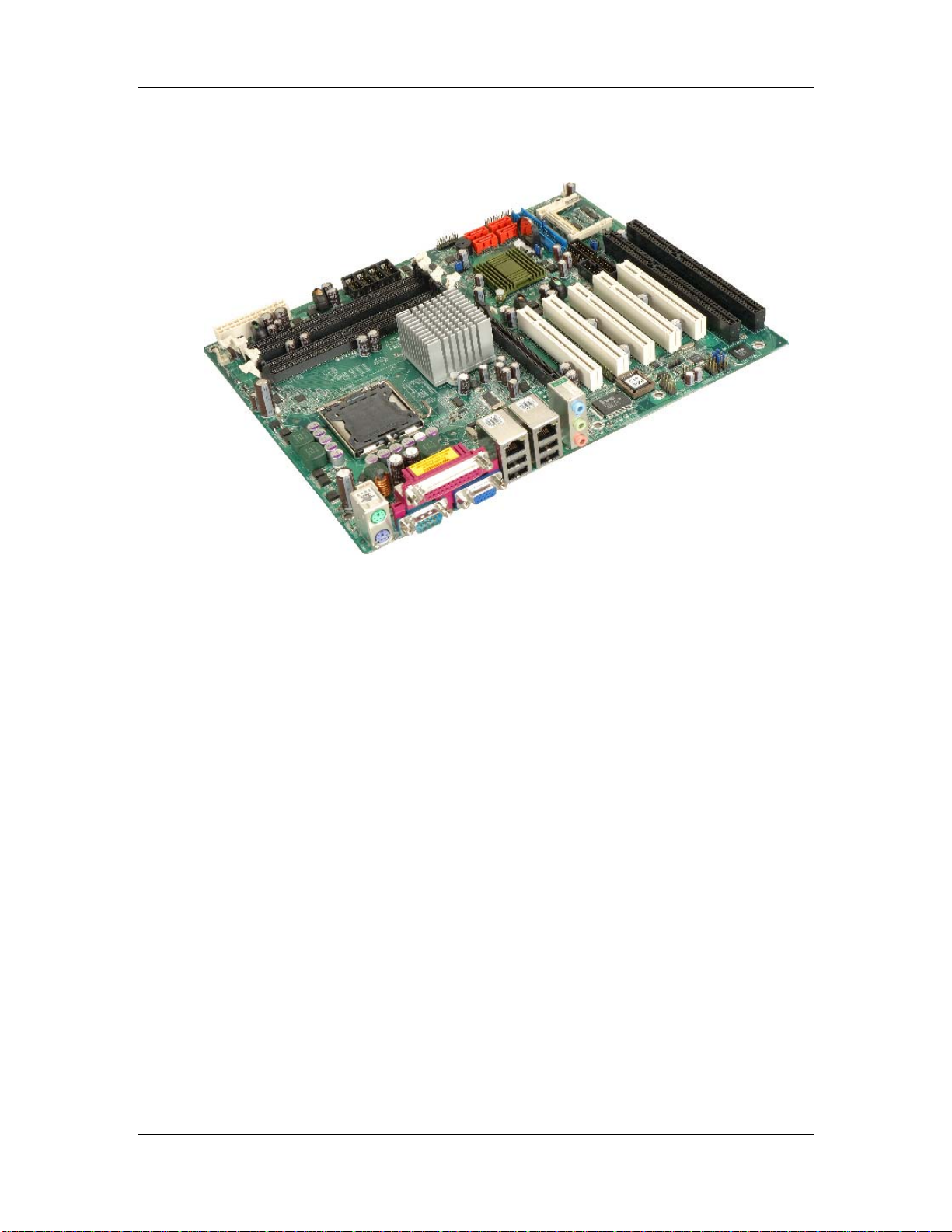
Figure 1-1: MXGE Motherboard...................................................................................2
Figure 1-2: MXGE Overview [Front View] ...................................................................4
Figure 2-1: MXGE Dimensions (mm).........................................................................10
Figure 2-2: External Interface Panel Dimensions (mm)...........................................10
Figure 2-3: Data Flow Block Diagram........................................................................11
Figure 2-4: LGA775 CPU Socket................................................................................12
Figure 2-5: 240-pin DIMM Sockets.............................................................................15
Figure 2-6: PCIe x16 Socket.......................................................................................17
Figure 2-7: Audio Connectors....................................................................................20
Figure 2-8: IDE Connector..........................................................................................23
Figure 2-9: PCI Slots...................................................................................................25
Figure 2-10: ISA Bus...................................................................................................26
Figure 2-11: PCIe GbE.................................................................................................27
Figure 2-12: SATA Connectors...................................................................................29
Figure 2-13: USB Connectors....................................................................................30
Figure 2-14: LPC Bus Components...........................................................................31
Figure 4-1: Connector and Jumper Locations .........................................................44
Figure 4-2: ATX Power Connector Location .............................................................48
Figure 4-3: ATX Power Connector Pinout Locations...............................................49
Figure 4-4: Auxiliary Audio Connector Location (4-pin) .........................................50
Figure 4-5: Audio CD In Connector Pinouts (4-pin).................................................51
Figure 4-6: Audio Connector Location (10-pin)........................................................52
Figure 4-7: CF Card Socket Location........................................................................54
Figure 4-8: DIO Connector Connector Locations ....................................................56
Figure 4-9: +12V Fan Connector Location................................................................57
Figure 4-10: +12V Fan Connector Location..............................................................58
Figure 4-11: 34-pin FDD Connector Location...........................................................59
Figure 4-12: Front Panel Connector Pinout Locations (14-pin)..............................60
CyberResearch, Inc. xv
25 Business Park Drive P: (203) 483-8815; F: (203) 483-9024
Branford, CT USA www.cyberresearch.com
Page 16

MXGE Series CyberResearch® Motherboards
Figure 4-13: IDE Device Connector Locations.........................................................62
Figure 4-14: Infrared Connector Pinout Locations..................................................64
Figure 4-15: PCI Slot Location...................................................................................65
Figure 4-16: PCIe x16 Connector Location...............................................................68
Figure 4-17: SATA Drive Connector Locations.........................................................72
Figure 4-18: RS-232 COM Connector Pinout Locations..........................................73
Figure 4-19: RS-232/422/485 Serial Port Connector Location ................................74
Figure 4-20: RS-422/485 Serial Port Connector Location .......................................75
Figure 4-21: SPDIF Connector Pinout Locations.....................................................76
Figure 4-22: TPM Connector Pinout Locations........................................................77
Figure 4-23: USB Connector Pinout Locations........................................................78
Figure 4-24: MXGE External Interface Connectors..................................................79
Figure 4-25: PS/2 Pinouts...........................................................................................80
Figure 4-26: Parallel Port Connector Pinout Locations ..........................................81
Figure 4-27: Audio Connector....................................................................................82
Figure 4-28: RJ-45 Ethernet Connector ....................................................................83
Figure 4-29: USB Connector Pinout Locations........................................................84
Figure 4-30: VGA Connector......................................................................................84
Figure 4-31: Serial Communications Connector Pinout Locations .......................85
Figure 5-1: Intel LGA775 Socket................................................................................93
Figure 5-2: Remove the CPU Socket Protective Shield...........................................94
Figure 5-3: Open the CPU Socket Load Plate...........................................................94
Figure 5-4: Insert the Socket LGA775 CPU...............................................................95
Figure 5-5: Cooling Kit................................................................................................96
Figure 5-6: Cooling Kit................................................................................................96
Figure 5-7: Securing the Heat sink to the PCB Board.............................................98
Figure 5-8: Installing a DIMM......................................................................................99
Figure 5-9: CF Card Installation.............................................................................. 101
Figure 5-10: AT Power Select Jumper Location.................................................... 103
Figure 5-11: CF Card Setup Jumper Location....................................................... 104
Figure 5-12: Clear CMOS Jumper........................................................................... 105
Figure 5-13: COM 2 Function Select Jumper Location ........................................ 106
xvi ©Copyright 2009 CyberResearch, Inc.
Page 17

CyberResearch® Motherboards MXGE Series
Figure 5-14: IDE Cable Connection........................................................................ 108
Figure 5-15: FDD Cable Connection....................................................................... 109
Figure 5-16: Dual RS-232 Cable Installation...........................................................110
Figure 5-17: Dual Serial Port Connector Cable Connection.................................111
Figure 5-18: SATA Drive Cable Connection............................................................112
Figure 5-19: SATA Power Drive Connection...........................................................113
Figure 5-20: Dual USB Cable Connection...............................................................114
Figure 5-21: Four Port USB Cable Connection ......................................................115
Figure 5-22: Audio Connectors................................................................................116
Figure 5-23: LAN Connection...................................................................................117
Figure 5-24: Parallel Device Connector ..................................................................118
Figure 5-25: PS/2 Keyboard/Mouse Connector......................................................119
Figure 5-26: Serial Device Connector .................................................................... 120
Figure 5-27: USB Connector ................................................................................... 121
Figure 5-28: VGA Connector................................................................................... 122
Figure 7-1: Introduction Screen.............................................................................. 185
Figure 7-2: Available Drivers................................................................................... 185
Figure 7-3: Chipset Driver Installation Program................................................... 186
Figure 7-4: Chipset Driver Installation Welcome Screen ..................................... 186
Figure 7-5: Chipset Driver Installation License Agreement ................................. 187
Figure 7-6: Chipset Driver Readme File Information............................................ 187
Figure 7-7: Chipset Driver Installation Complete.................................................. 188
Figure 7-8: Select the Operating System............................................................... 189
Figure 7-9: VGA Driver............................................................................................. 189
Figure 7-10: Intel® Graphics Media Accelerator InstallShield Wizard................ 190
Figure 7-11: InstallShield Wizard Extracting Files................................................ 190
Figure 7-12: Intel® Graphics Media Accelerator Driver W elcome Screen.......... 191
Figure 7-13: Intel® Graphics Media Accelerator Driver License Agreement ..... 191
Figure 7-14: Intel® Graphics Media Accelerator Driver Installing Notice........... 192
Figure 7-15: Intel® Graphics Media Accelerator Installation Complete.............. 192
Figure 7-16: Windows Control Panel...................................................................... 193
Figure 7-17: System Icon......................................................................................... 194
CyberResearch, Inc. xvii
25 Business Park Drive P: (203) 483-8815; F: (203) 483-9024
Branford, CT USA www.cyberresearch.com
Page 18

MXGE Series CyberResearch® Motherboards
Figure 7-18: Device Manager Tab ........................................................................... 194
Figure 7-19: Device Manager List........................................................................... 195
Figure 7-20: Search for Suitable Driver.................................................................. 196
Figure 7-21: Locate Driver Files.............................................................................. 196
Figure 7-22: Location Browsing Window............................................................... 197
Figure 7-23: Select the Audio CODEC.................................................................... 198
Figure 7-24: Select the OS....................................................................................... 199
Figure 7-25: Select the OS Version......................................................................... 199
Figure 7-26: Locate the Setup Program Icon......................................................... 200
Figure 7-27: The InstallShield Wizard Starts ......................................................... 200
Figure 7-28: Preparing Setup Screen..................................................................... 201
Figure 7-29: InstallShield Wizard Welcome Screen.............................................. 201
Figure 7-30: Audio Driver Software Configuration ............................................... 202
Figure 7-31: Installation Wizard Updates the System........................................... 202
Figure 7-32: Restart the Computer......................................................................... 203
Figure 7-33: SATA RAID Driver Installation Program............................................ 204
Figure 7-34: SATA RAID Setup Program Icon........................................................ 205
Figure 7-35: InstallShield Wizard Setup Screen.................................................... 205
Figure 7-36: Matrix Storage Manager Setup Screen............................................. 206
Figure 7-37: Matrix Storage Manager Welcome Screen....................................... 206
Figure 7-38: Matrix Storage Manager Warning Screen......................................... 207
Figure 7-39: Matrix Storage Manager License Agreement................................... 207
Figure 7-40: Matrix Storage Manager Readme File............................................... 208
Figure 7-41: Matrix Storage Manager Setup Complete ........................................ 208
xviii ©Copyright 2009 CyberResearch, Inc.
Page 19

CyberResearch® Motherboards MXGE Series
List of Tables
Table 1-1: Technical Specifications.............................................................................7
Table 2-1: Supported HDD Specifications ................................................................22
Table 2-2: Power Consumption..................................................................................36
Table 3-1: Package List Contents..............................................................................40
Table 3-2: Package List Contents..............................................................................42
Table 4-1: Peripheral Interface Connectors..............................................................46
Table 4-2: Rear Panel Connectors.............................................................................47
Table 4-3: ATX Power Connector Pinouts.................................................................48
Table 4-4: ATX Power Connector Pinouts.................................................................49
Table 4-5: Auxiliary Audio Connector Pinouts (4-pin).............................................50
Table 4-6: Audio CD In Connector Pinouts...............................................................51
Table 4-7: Audio Connector Pinouts..........................................................................53
Table 4-8: CF Card Socket Pinouts............................................................................55
Table 4-9: DIO Connector Connector Pinouts..........................................................56
Table 4-10: +12V Fan Connector Pinouts..................................................................57
Table 4-11: +12V Fan Connector Pinouts..................................................................58
Table 4-12: 34-pin FDD Connector Pinouts ..............................................................60
Table 4-13: Front Panel Connector Pinouts (14-pin)................................................61
Table 4-14: IDE Connector Pinouts............................................................................63
Table 4-15: Infrared Connector Pinouts....................................................................64
Table 4-16: PCI Slot.....................................................................................................67
Table 4-17: PCIe x16 Side A Pinouts..........................................................................70
Table 4-18: PCIe x16 Side B Pinouts .........................................................................71
Table 4-19: SATA Drive Connector Pinouts ..............................................................72
Table 4-20: RS-232 COM Connector Pinouts............................................................73
Table 4-21: RS-232/RS-485 Serial Port Connector Pinouts.....................................74
Table 4-22: RS-422/485 Serial Port Connector Pinouts...........................................76
Table 4-23: SPDIF Connector Pinouts.......................................................................77
CyberResearch, Inc. xix
25 Business Park Drive P: (203) 483-8815; F: (203) 483-9024
Branford, CT USA www.cyberresearch.com
Page 20

MXGE Series CyberResearch® Motherboards
Table 4-24: TPM Connector Pinouts..........................................................................78
Table 4-25: USB Port Connector Pinouts..................................................................79
Table 4-26: PS/2 Connector Pinouts..........................................................................80
Table 4-27: Parallel Pinouts........................................................................................81
Table 4-28: LAN Pinouts.............................................................................................83
Table 4-29: RJ-45 Ethernet Connector LEDs............................................................83
Table 4-30: USB Connector Pinouts..........................................................................84
Table 4-31: VGA Connector Pinout s..........................................................................85
Table 4-32: COM1 RS-232 Mode Connector Pinouts ...............................................86
Table 5-1: Jumpers................................................................................................... 102
Table 5-2: AT Power Select Jumper Settings......................................................... 102
Table 5-3: CF Card Setup Jumper Settings ........................................................... 103
Table 5-4: Clear CMOS Jumper Settings................................................................ 105
Table 5-5: COM 2 Function Select Jumper Settings............................................. 106
Table 5-6: Cables Provided with Board.................................................................. 107
Table 6-1: BIOS Navigation Keys............................................................................ 125
xx ©Copyright 2009 CyberResearch, Inc.
Page 21

CyberResearch® Motherboards MXGE Series
BIOS Menus
Menu 1: Main............................................................................................................. 126
Menu 2: Advanced.................................................................................................... 128
Menu 3: CPU Configuration..................................................................................... 129
Menu 4: IDE Configuration ...................................................................................... 130
Menu 5: IDE Master and IDE Slave Configuration ................................................ 132
Menu 6: IDE Master and IDE Slave Configuration ................................................ 138
Menu 7: Super IO Configuration............................................................................. 139
Menu 8: Hardware Health Configuration................................................................ 144
Menu 9: Power Configuration ................................................................................. 148
Menu 10: ACPI Configuration.................................................................................. 149
Menu 11:Adv anced Power Management Configuration....................................... 150
Menu 12: Remote Access Configuration [Advanced]........................................... 153
Menu 13: Tr usted Computing.................................................................................. 157
Menu 14: USB Configuration .................................................................................. 158
Menu 15: USB Mass Storage Device Configuration.............................................. 160
Menu 16: PCI/PnP Configuration............................................................................ 163
Menu 17: Boot........................................................................................................... 165
Menu 18: Boot Settings Configuration................................................................... 166
Menu 19: Boot Device Priority Settings................................................................. 168
Menu 20: Removable Drives ................................................................................... 170
Menu 21: USB Drives............................................................................................... 171
Menu 22: Security..................................................................................................... 172
Menu 23: Chipset...................................................................................................... 174
Menu 24:NorthBridge Chipset Configuration........................................................ 175
Menu 25:SouthBridge Chipset Configuration....................................................... 178
Menu 26:Exit............................................................................................................. 180
CyberResearch, Inc. xxi
25 Business Park Drive P: (203) 483-8815; F: (203) 483-9024
Branford, CT USA www.cyberresearch.com
Page 22

Page 23

CyberResearch® Motherboards MXGE Series
Chapter
1
1 Introduction
CyberResearch, Inc. 1
25 Business Park Drive P: (203) 483-8815; F: (203) 483-9024
Branford, CT USA www.cyberresearch.com
Page 24
MXGE Series CyberResearch® Motherboards
1.1 Overview
Figure 1-1: MXGE Motherboard
The MXGE ATX form factor motherboard is a LGA775 Intel® Core™2 Duo, Pentium® 4 or
Celeron® D platform with a 533 MHz, 800 MHz or 1066 MHz front side bus (FSB). Up to
4.0 GB of DDR2 SDRAM and up to four SATA II hard disk drives (HDD) are supported.
High-performance PCI Express (PCIe) Gigabit Ethernet (GbE) connectivity is integrated
into the system. Four or five PCI slots, two or one ISA slots and eight USB 2.0 connectors
(four external and four internal) provide flexible expansion options. Added system security
is provided with Trusted Platform Module (TPM v1.2) support. An external VGA connector
and three audio-jacks facilitate multi-media applications.
1.1.1 MXGE Features
Some of the MXGE features are listed below.
Supports LGA775 Intel® CPUs including:
o Intel® Core™2 Duo
o Intel® Pentium® 4
o Intel® Celeron® D
2 ©Copyright 2009 CyberResearch, Inc.
Page 25

CyberResearch® Motherboards MXGE Series
Maximum FSB of 1066 MHz
Supports four 240-pin 533 MHz or 667 MHz 1.0 GB (max.) DDR2 memory
modules
Added security with support for TPM v1.2
Expansion slots include:
o Five PCI slots
o Two ISA slots
Four SATA II drives with transfer rates of 3.0 Gbps supported
Eight USB 2.0 devices supported
Dual PCIe GbE Ethernet connectors
ATX form factor
RoHS compliant
Supports ATX power supplies
1.2 MXGE Overview
1.2.1 MXGE Overview Photo
The MXGE has a wide variety of peripheral interface connectors. Figure 1-2 is a labeled
photo of the peripheral interface connectors on the MXGE.
CyberResearch, Inc. 3
25 Business Park Drive P: (203) 483-8815; F: (203) 483-9024
Branford, CT USA www.cyberresearch.com
Page 26

MXGE Series CyberResearch® Motherboards
Figure 1-2: MXGE Overview [Front View]
1.2.2 MXGE Peripheral Connectors and Jumpers
The MXGE has the following connectors on-board:
1 x ATX +12V power connector
1 x ATX power connector
1 x Audio auxiliary in connector
1 x Audio CD In connector
1 x Audio connector (front panel)
1 x Audio connector
4 ©Copyright 2009 CyberResearch, Inc.
Page 27

CyberResearch® Motherboards MXGE Series
1x CF card Type II socket
1 x CPU cooling fan connector
2 x System cooling fan connectors
1 x Digital input/output (DIO) connector
1 x Floppy disk connector
1 x Front panel connector
1 x IDE connector
1 x Infrared connector
2 x ISA sockets
5 x PCI sockets
4 x RS-232 serial port connectors
1 x RS-232/422/485 serial port connector
4 x Serial ATA drive connectors
1 x Serial port (COM2) select RS-232/422/485
1 x SPDIF connector
1 x TPM connector
2 x USB connectors
The MXGE has the following external peripheral interface connectors on the board rear
panel
3 x Audio jacks
2 x Ethernet connectors
1 x Parallel port connector
2 x PS/2 connectors
1 x Serial port connector
4 x USB 2.0 port connectors
1 x VGA connector
The MXGE has the following on-board jumpers:
AT power select
Clear CMOS
CF card setting
Select RS-232/422/485 for COM2
CyberResearch, Inc. 5
25 Business Park Drive P: (203) 483-8815; F: (203) 483-9024
Branford, CT USA www.cyberresearch.com
Page 28

MXGE Series CyberResearch® Motherboards
1.3 Technical Specifications
MXGE technical specifications are listed in Table 1-1. See Chapter 2 for details.
Specification MXGE
Form Factor
System CPU
Front Side Bus
System Chipset
Memory
Display
BIOS
ATX
LGA775 Intel® Core™ 2 Duo
LGA775 Intel® Pentium® 4
LGA775 Intel® Celeron® D
533 MHz, 800 MHz or 1066 MHz
Northbridge: Intel® 945
Southbridge: Intel® ICH7
Four dual channel 240-pin DDR2 DIMM sockets supp ort
four 533 MHz or 667 MHz 1.0 GB (max.) DIMM. A m aximum
of 4.0 GB of DDR2 is supported.
VGA integrated into the Intel® 945G
AMI Flash BIOS
Audio
TPM
Realtek ALC655 AC’97 codec
One 20-pin connector TPM v1.2 module
Five PCI slots
Expansion Options
Two ISA slots
Infrared (IrDA)
One infrared interface
Dual Broadcom BCM5787M PCIe GbE chipsets with ASF
LAN
2.0 support
SuperIO
SSD
ITE IT8712F
CF Type II
6 ©Copyright 2009 CyberResearch, Inc.
Page 29

CyberResearch® Motherboards MXGE Series
Digital I/O
COM
USB 2.0
IDE
SATA
Keyboard/mouse
Parallel Port
Watchdog Timer
Power Supply
8-bit digital I/O, 4-bit input/4-bit output
Five RS-232 serial ports (four internal, one external)
One RS-232, RS-422 or RS-485 serial port (internal)
Eight USB 2.0 devices supported
One 40-pin IDE connector connects to two Ultra
ATA33/66/100 devices
Four 3.0 Gbps SATA II drives supported
Two PS/2 connectors for keyboard and mouse
One external parallel port connects to parallel
communications device (e.g. printer)
Software programmable 1-255 sec. by super I/O
ATX power only
5 V @ 4.25 A, 12 V @ 10.17 A and 3.3 V @ 6.07 A
Power Consumption
Temperature
Humidity (operating)
Dimensions (LxW)
Weight (GW/NW)
Table 1-1: Technical Specifications
(Intel® Pentium® 4 3.73GHz, 1066MHz FSB CPU and 1GB
667MHz DDR2)
0ºC – 60ºC (32ºF - 140ºF)
5%~95% non-condensing
305 mm x 244 mm
1200g/650g
CyberResearch, Inc. 7
25 Business Park Drive P: (203) 483-8815; F: (203) 483-9024
Branford, CT USA www.cyberresearch.com
Page 30

MXGE Series CyberResearch® Motherboards
Intentionally Blank
8 ©Copyright 2009 CyberResearch, Inc.
Page 31

CyberResearch® Motherboards MXGE Series
Chapter
2
2 Detailed Specifications
CyberResearch, Inc. 9
25 Business Park Drive P: (203) 483-8815; F: (203) 483-9024
Branford, CT USA www.cyberresearch.com
Page 32

MXGE Series CyberResearch® Motherboards
2.1 Dimensions
2.1.1 Board Dimensions
The dimensions of the board are listed below:
Length: 304.80mm
Width: 243.84mm
Figure 2-1: MXGE Dimensions (mm)
2.1.2 External Interface Panel Dimensions
External peripheral interface connector panel dimensions are shown in Figure 2-2.
Figure 2-2: External Interface Panel Dimensions (mm)
10 ©Copyright 2009 CyberResearch, Inc.
Page 33

CyberResearch® Motherboards MXGE Series
2.2 Data Flow
Figure 2-3 shows the data flow between the two on-board chip set s and other components
installed on the motherboard and described in the following se ctions of this chapter.
Figure 2-3: Data Flow Block Diagram
CyberResearch, Inc. 11
25 Business Park Drive P: (203) 483-8815; F: (203) 483-9024
Branford, CT USA www.cyberresearch.com
Page 34

MXGE Series CyberResearch® Motherboards
2.3 Compatible Processors
The MXGE supports the following LGA775 processors:
Intel® Core™2 Duo
Intel® Pentium® 4
Intel® Celeron® D
All of the above processors are interfaced with an Intel® 945G northbridge chipset through
the front side bus (FSB).
Figure 2-4: LGA775 CPU Socket
Features of the supported processors are listed in sections below.
12 ©Copyright 2009 CyberResearch, Inc.
Page 35

CyberResearch® Motherboards MXGE Series
2.3.1 Intel® Core™2 Duo Features
Intel® Core™2 Duo features include:
Two processing cores
Up to 8MB of shared L2 cache
Up to 1066 MHz FSB
Intel® Wide Dynamic Execution
Intel® Intelligent Power Capability Intel® Smart Memory Access
Intel® Advanced Smart Cache
Intel® Advanced Digital Media Boost
2.3.2 Intel® Pentium® 4 Features
Intel® Pentium® 4 features include:
Hyper-Threading Technology
Enhanced Intel SpeedStep® Technology
Intel® Extended Memory 64 Technology
Execute Disable Bit
2.3.3 Intel® Celeron® D Features
Intel® Celeron® D features include:
Intel® Extended Memory 64 Technology
512KB Level 2 cache
533MHz FSB
Execute Disable Bit
Streaming SIMD sol ution s
2.4 Intel® 945G Northbridge Chipset
2.4.1 Intel® 945G Overview
The Intel® 945G graphics and memory controller hub (GMCH) is interfaced to the Intel®
I/O Controller Hub 7 (ICH7) through a high speed Direct Media Interface (DMI)
chip-to-chip connection. The high-speed DMI integrates priority based servicing that
CyberResearch, Inc. 13
25 Business Park Drive P: (203) 483-8815; F: (203) 483-9024
Branford, CT USA www.cyberresearch.com
Page 36

MXGE Series CyberResearch® Motherboards
allows for concurrent traffic and true isochronous transfer capabilities. Some of the
features of the Intel® 945G are listed below.
Support 533/800/1066MHz FSB
Supports four, 1GB, 400/533/667MHz dual channel DDR SDRAM DIMMs
Integrated VGA and SDVO (Serial Digital Video Output) outputs
Integrated Intel
2.0GB/s concurrent DMI bandwidth maximizes chip set communications
PCI Express x16 Graphics Interface with a raw bit rate on data pins of 2Gb/s
Integrated Intel® High Definition Audio
Integrated Intel® Matrix Storage Technology
Integrated Intel® Active Management Technology
Integrated Intel® Flex Memory Technology
®
Graphics Media Accelerator 950 (Intel® GMA 950)
2.4.2 Intel® 945G Memory Support
The Intel® 945G supports four, 1.0 GB, 400/533/667MHz dual channel DDR2 SDRAM
DIMMs. Four 240-pin memory sockets on the MXGE enable a maximum of 4GB of DDR2
memory to be installed on the system. The memory sockets are shown in Figure 2-1.
14 ©Copyright 2009 CyberResearch, Inc.
Page 37

CyberResearch® Motherboards MXGE Series
Figure 2-5: 240-pin DIMM Sockets
2.4.3 Intel® 945G Integrated Graphics Media Accelerator 950
The Intel® 945G has the Intel® GMA 950 integrated into the chi pset. Some of the feature s
of the GMA 950 are listed below.
Intel GMA 950 Grap hics Core
o 400MHz 256-bit graphics core
o Up to 10.6 GB/sec memory bandwidth with DDR2 667 MHz system
memory
o 1.6 GPixels/sec and 1.6 GTexels/sec fill rate
o 192 MB maximum video memory
o 2048x1536 at 75 Hz maximum resolution
o Dynamic Display Modes for flat-panel, wide-screen and Digital TV support
CyberResearch, Inc. 15
25 Business Park Drive P: (203) 483-8815; F: (203) 483-9024
Branford, CT USA www.cyberresearch.com
Page 38

MXGE Series CyberResearch® Motherboards
o Operating systems supported: Microsoft Windows* XP, Windows* XP
64-bit, Media Center Edition, Windows 2000; Linux-compatible (Xfree86
source available)
High Performance 3D
o Up to 4 pixels per clock rendering
o Microsoft* DirectX* 9 Hardware Acceleration Features: Pixel Shader 2,
Volumetric Textures, Shadow Maps, Slope Scale Depth Bias, Two-Sided
Stencil
o Microsoft* DirectX* 9 Vertex Shader 3.0 and Transform and Lighting
supported in SW through highly optimized Processor Specific Geometry
Pipeline (PSGP)
o Texture Decompression for DirectX* and OpenGL*
o OpenGL* 1.4 support with ARB extensions
Advanced Display Technology
o Consumer Electronic display (Digital TV) support
o Two Serial Digital Video Out (SDVO) ports for flat-panel monitors via
ADD2 cards
o Multiple display types (LVDS, DVI-I, DVI-D, CRT)
o Dual screen support via ADD2 digital video devices
o HDTV 720p and 1080i display resolution support
o Interlaced Display output support
High Quality Media Support
o High Definition Hardware Motion Compensation to support HD hi-bitrate
MPEG2 media playback
o Up and Down Scaling of Video Content
o HD Content Decode – up to two stream support
o 5x3 Overlay Filtering
2.4.4 Intel® 945G PCIe x16
The Intel® 945G northbridge chipset has a dedicated 16-lane PCIe port for an external
PCIe x16 graphics card. The PCIe x16 graphics card is installed in the on-board PCIe x16
slot shown in Figure 2-6.
16 ©Copyright 2009 CyberResearch, Inc.
Page 39

CyberResearch® Motherboards MXGE Series
Figure 2-6: PCIe x16 Socket
2.4.4.1 PCIe x16 Bus Specifications
Some of the PCIe x16 bus specifications are listed below.
Compliant with the current PCI Express Base Specification base PCIe
frequency of 2.5GHz
Raw bit rate on the pins is 250Gb/s
Maximum theoretical bandwidth of 4GB/s in each direction resulting in an
8GB/s bandwidth when in PCIe x16 mode
100MHz differential reference clock
PCIe power management support
L0, L1, L2/L3 ready, L3
Hierarchical PCI compliant configuration mechanism for downstream
components
PCIe extended configuration space
PCIe enhanced addressing mechanism
CyberResearch, Inc. 17
25 Business Park Drive P: (203) 483-8815; F: (203) 483-9024
Branford, CT USA www.cyberresearch.com
Page 40

MXGE Series CyberResearch® Motherboards
Supports traditional PCI traffic
Supports traditional AGP traffic
APIC and MSI messaging support
2.4.5 Intel® 945G Integrated Graphics
The Intel® 945G northbridge chipset has an Intel® Gen. 3.5 integrated graphics engine
that supports CRT display devices. A DB-15 VGA connector on the external peripheral
interface connector panel is interfaced to the Intel® 945GM graphics engine. The Intel
945GM internal graphics engine, with an integrated 400MHz RAMDAC and hot plug CRT
support, supports analog CRT monitors up to QXGA.
2.4.6 Intel® 945G Direct Media Interface (DMI)
Intel® 945G northbridge GMCH is connected to the Intel® ICH7 Southbridge Chipset
through the chip-to-chip Direct Media Interface (DMI). Features of the Intel
®
945GM DMI
®
are listed below:
2GB/s (1GB/s in each direction) bus speed
32-bit downstream address
2.5 Intel® ICH7 Southbridge Chipset
2.5.1 Intel® ICH7 Overview
The ICH7 southbridge chipset on the MXGE has the features are listed below.
Complies with PCI Express Base Specification, Revision 1.0a
Complies with PCI Local Bus Spe cificati on, Revision 2.3 and su pports 33MHz
PCI operations
Supports ACPI Power Management Logic
Contains:
o Enhanced DMA controller
o Interrupt controller
o Timer functions
Integrated SATA host controller with DMA operations on four ports with data
transfer rates up to 3.0 Gb/s
18 ©Copyright 2009 CyberResearch, Inc.
Page 41

CyberResearch® Motherboards MXGE Series
Integrated IDE controller supports Ultra ATA 100/66/33
Supports eight USB 2.0 devices with four UHCI controllers and one EHCI
controller
Complies with System Management Bus (SMBus) Specification, Version 2.0
Supports Audio Codec ’97 (AC’97) Revision 2.3
Supports Intel
Contains Low Pin Count (LPC) interface
Supports Firmware Hub (FWH) interface
Serial Peripheral Interface (SPI) for Serial and Shared Flash
1.05 V Core Voltage
Intel® High Definition Audio Interface
Intel® Active Management T echnology
Intel® Quick Resume Technology Support
®
High Definition Audio
2.5.2 Intel® ICH7 Audio Codec ’97 Controller
NOTE:
The onboard audio connector and the audio jacks cannot be used
concurrently. If the audio jacks are being used, the jumper headers
inserted on the onboard audio connector must remain in place. If the
onboard audio connector is used, the jumper headers must be
removed and the audio jack functions are disabled.
The Audio Codec ’97 (AC’97) controller integrated into the ICH7 complies with AC’97
Component Specification, Version 2.3. The AC’97 controller is interfaced to a RealTek
ALC655 AC’97 codec which is in turn connected to the following audio connectors:
CD-In connector (pin header)
Audio connector (pin header)
Auxiliary audio connector (pin header)
SPDIF connector (pin header)
Surround sound speaker connector (pin header)
CyberResearch, Inc. 19
25 Business Park Drive P: (203) 483-8815; F: (203) 483-9024
Branford, CT USA www.cyberresearch.com
Page 42

MXGE Series CyberResearch® Motherboards
Audio jacks (phone jacks)
o Mic-In
o Line-In
o Line-Out
Figure 2-7: Audio Connectors
Some of the features of the RealTek ALC655 are listed below:
Meets performance requirements for audio on PC99/2001 systems
Meets Microsoft WHQL/WLP 2.0 audio requirements
16-bit Stereo full-duplex CODEC with 48KHz sampling rate
Compliant with AC'97 Rev 2.3 specifications
o Front-Out, Surround-Out, MIC-In and LINE-In Jack Sensing
o 14.318MHz -> 24.576MHz PLL to eliminate crystal
o 12.288MHz BITCLK input
20 ©Copyright 2009 CyberResearch, Inc.
Page 43

CyberResearch® Motherboards MXGE Series
o Integrated PCBEEP generator to save buzzer
o Interrupt capability
Three analog line-level stereo inputs with 5-bit volume control, LINE_IN, CD,
AUX
High-quality differential CD input
Two analog line-level mono inputs: PCBEEP, PHONE-IN
Two software selectable MIC inputs
Dedicated Front-MIC input for front panel applications (software selectable)
Boost preamplifier for MIC input
LINE input shared with surround output; MIC input shared with Center and
LFE output
Built-in 50mW/20ohm amplifier for both Front-out and Surround-Out
External Amplifier Power Down (EAPD) capability
Power management and enhanced power saving features
Supports Power-Off CD function
Adjustable VREFOUT control
Supports 48KHz S/PDIF output, complying with AC'97 Rev 2.3 specifications
Supports 32K/44.1K/48KHz S/PDIF input
Power support: Digital: 3.3V; Analog: 3.3V/5V
Standard 48-pin LQFP package
EAX™ 1.0 & 2.0 compatible
Direct Sound 3D™ compatible
A3D™ compatible
I3DL2 compatible
HRTF 3D positional audio10-band software equali zer
2.5.3 Intel® ICH7 IDE Interface
The integrated IDE interface on the ICH7 southbridge supports two IDE hard disks and
ATAPI devices, PIO IDE transfers up to 16MB/s and Ultra ATA transfers of 100MB/s. The
integrated IDE interface is able to support the following IDE HDDs:
Ultra A T A/10 0, with data transfer rates up to 100MB/s
Ultra A T A/66, with data transfer rates up to 66MB/s
Ultra A T A/33, with data transfer rates up to 33MB/s
CyberResearch, Inc. 21
25 Business Park Drive P: (203) 483-8815; F: (203) 483-9024
Branford, CT USA www.cyberresearch.com
Page 44

MXGE Series CyberResearch® Motherboards
Table 2-1 shows the supported HDD specifications.
Specification
IDE devices
PIO Mode
PIO Max Transfer Rate
DMA/UDMA designation
DMA/UDMA Max Transfer
Controller Interface
Ultra A T A/10 0 Ultra A T A/66 Ultra A T A/33
2 2 2
0 – 4 0 – 4 0 – 4
16.6 MB/s 16.6 MB/s 16.6 MB/s
UDMA 3 - 4 UDMA 3 – 4 UDMA 2
100MB/s 66MB/s 33MB/s
5V 5V 5V
Table 2-1: Supported HDD Specifications
The IDE connector is shown below
22 ©Copyright 2009 CyberResearch, Inc.
Page 45

CyberResearch® Motherboards MXGE Series
Figure 2-8: IDE Connector
2.5.4 Intel® ICH7 Low Pin Count (LPC) Interface
The ICH7 LPC interface complies with the LPC 1.1 specifications. The LPC bus from the
ICH7 is connected to the following components:
BIOS chipset
Super I/O chipset
Serial port controller
CyberResearch, Inc. 23
25 Business Park Drive P: (203) 483-8815; F: (203) 483-9024
Branford, CT USA www.cyberresearch.com
Page 46

MXGE Series CyberResearch® Motherboards
2.5.5 Intel® ICH7 PCI Interface
NOTE:
PCI and ISA slots can only be used in the following configuration:
Five PCI slots and one ISA slot OR
Four PCI slots and two ISA slots can be
The five PCI slots cannot be used with two ISA slots concurrently.
The PCI interface on the ICH7 is compliant with the PCI Revision 2.3 implementation.
Some of the features of the PCI interface are listed below.
PCI Revision 2.3 compliant
33MHz
5V tolerant PCI signals (except PME#)
Integrated PCI arbiter supports up to six external PCI bus masters
Five of the six PCI bus masters are interfaced to five PCI slots. The remaining PCI bus
master is interfaced to an ITE IT8888G PCI-to-ISA bridge, which is then connected to two
ISA slots.
24 ©Copyright 2009 CyberResearch, Inc.
Page 47

CyberResearch® Motherboards MXGE Series
Figure 2-9: PCI Slots
2.5.5.1 PCI-to-ISA Bridge
The IT8888G has a PCI specification v2.1 compliant 32-bit PCI bus interface and supports
both PCI Bus master and slave. The PCI interface supports both programmable positive
and full subtractive decoding schemes. The ISA bridge and sockets are shown below.
CyberResearch, Inc. 25
25 Business Park Drive P: (203) 483-8815; F: (203) 483-9024
Branford, CT USA www.cyberresearch.com
Page 48

MXGE Series CyberResearch® Motherboards
Figure 2-10: ISA Bus
Some of the features of the IT8888G PCI to ISA bridge are listed below.
PCI Interface
Programmable PCI Address Decoders
PC/PCI DMA Controller
Distributed DMA Controller
ISA Interface
SM Bus
1 analog line-level mono output: MONO_OUT
Power-on Serial Bus Configuration
Serial IRQ
Versatile power-on strapping options
Supports NOGO function
Single 33 MHz Clock Input
26 ©Copyright 2009 CyberResearch, Inc.
Page 49

CyberResearch® Motherboards MXGE Series
+3.3V PCI I/F with +5V tolerant I/O buffers
+5V ISA I/F and core Power Supply
2.5.6 PCI Express Gigabit Ethernet
Two of the PCIe x1 root ports on the Intel® ICH7 are interfaced to two Broadcom
BCM5787M PCI Express (PCIe) GbE controllers. The Broadcom BCM5787M PCI
Express (PCIe) GbE controller is a 10/100/1000BASE-T Ethernet LAN controller. The
BCM5787M combines a triple-speed IEEE 802.3 compliant Media Access Controller
(MAC) with a triple-speed Ethernet transceiver, a PCIe bus interface, and an on-chip
buffer memory.
Figure 2-11: PCIe GbE
Some of the BCM5787 controller features are listed below:
CyberResearch, Inc. 27
25 Business Park Drive P: (203) 483-8815; F: (203) 483-9024
Branford, CT USA www.cyberresearch.com
Page 50

MXGE Series CyberResearch® Motherboards
Integrated 10/100/1000BASE-T transceiver
Automatic MDI crossover function
PCIe v1.0a
10/100/1000BASE-T full/half-duplex MAC
Wake on LAN support meeting the ACPI requirements
Statistics for SNMP MIB II, Ethernet-like MIB, and Ethernet MIB (802.3z,
clause 30)
Serial EEPROM or serial flash support
JT A G sup po rt
2.5.7 Intel® ICH7 Real Time Clock
256 bytes of battery backed RAM is provided by the Motorola MC146818A real time clock
(RTC) integrated into the ICH7. The RTC operates o n a 3V battery and 32.768KHz cryst al.
The RTC keeps track of the time and stores system data even when the system is turned
off.
2.5.8 Intel® ICH7 SATA Controller
The integrated SATA controller on the ICH7 southbridge supports four SATA drives with
independent DMA operations. SATA controller specifications are listed below.
Supports four SATA drives
Supports 3.0Gb/s data transfer spe eds
Supports Serial ATA Specification, Revision 1.0a and supports several
optional sections of the Serial ATA II: Extensions to Serial ATA 1.0
Specification, Revision 1.0 (AHCI sup port is required for some elements).
28 ©Copyright 2009 CyberResearch, Inc.
Page 51

CyberResearch® Motherboards MXGE Series
Figure 2-12: SATA Connectors
2.5.9 Intel® ICH7 USB Controller
Up to eight high-speed, full-speed or low-speed USB devices are supported by the ICH7
on the MXGE. High-speed USB 2.0, with data transfers of up to 480MB/s, is enabled with
the ICH7 integrated Enhanced Host Controller Interface (EHCI) compliant host controller.
USB full-speed and low-speed signaling is supported by the ICH7 integrated Universal
Host Controller Interface (UHCI) controllers.
Four of the USB ports are accessed through two 4-pin pin headers. The remaining four
USB ports are external USB connectors.
CyberResearch, Inc. 29
25 Business Park Drive P: (203) 483-8815; F: (203) 483-9024
Branford, CT USA www.cyberresearch.com
Page 52

MXGE Series CyberResearch® Motherboards
Figure 2-13: USB Connectors
2.6 LPC Bus Components
2.6.1 LPC Bus Overview
The LPC bus is connected to components listed belo w:
BIOS chipset
Super I/O chipset
Serial port chipset
30 ©Copyright 2009 CyberResearch, Inc.
Page 53

CyberResearch® Motherboards MXGE Series
Figure 2-14: LPC Bus Components
2.6.2 BIOS Chipset
The BIOS chipset has a licensed copy of AMI BIOS installed on the chipset. Some of the
BIOS features are listed below:
AMI Flash BIOS
SMIBIOS (DMI) compliant
Console redirection function support
PXE (Pre-boot Execution Environment) support
USB booting support
CyberResearch, Inc. 31
25 Business Park Drive P: (203) 483-8815; F: (203) 483-9024
Branford, CT USA www.cyberresearch.com
Page 54

MXGE Series CyberResearch® Motherboards
2.6.3 Super I/O chipset
The iTE IT8712F Super I/O chipset is connected to the ICH8DO southbridge through the
LPC bus. The iTE IT8712F is an LPC interface-based Super I/O device that comes with
Environment Controller integration. Some of the features of the iTE IT8712F chipset are
listed below:
PC98/99/2001, ACPI and LANDesk Compliant
Enhanced Hardware Monitor
Fan Speed Controller
Single +5V Power Supply
Two 16C550 UARTs for serial port control
One IEEE 1284 Parallel Port
Keyboard Controller
Watchdog T i mer
Serial IRQ Support
Vbat & Vcch Support
Single +5V Power Supply
Some of the Super I/O features are described in more detail below:
2.6.3.1 Super I/O LPC Interface
The LPC interface on the Super I/O complies with the Intel® Low Pin Count Specification
Rev. 1.0. The LPC interface supports both LDRQ# and SERIRQ protocols as well as PCI
PME# interfaces.
2.6.3.2 Super I/O Digital Input/Output
The input mode supports switch debouncing or programmable external IRQ routing. The
output mode supports two sets of programmable LED blinking periods.
2.6.3.3 Super I/O 16C550 UARTs
The onboard Super I/O has two integrated 16C550 UARTs that can support the following:
Two standard serial ports (COM1 and COM2)
32 ©Copyright 2009 CyberResearch, Inc.
Page 55

CyberResearch® Motherboards MXGE Series
IrDa 1.0 and ASKIR protocols
Another two chipsets connected to the LPC bus provided connectivity to another four
serial port connectors
2.6.3.4 Super I/O Enhanced Hardware Monitor
The Super I/O Enhanced Hardware Monitor monitors three thermal inputs, VBAT
internally, and eight voltage monitor inputs. These hardware parameters are reported in
the BIOS and can be read from the BIOS Hardware Health Configuration menu.
2.6.3.5 Super I/O Fan Speed Controller
The Super I/O fan speed controller enables the system to monitor the speed of the fan.
One of the pins on the fan connector is reserved for fan speed detection and interfaced to
the fan speed controller on the Super I/O. The fan speed is then reported in the BIOS.
2.6.3.6 Super I/O Floppy Disk Controller
The Super I/O floppy disk controller has the following specifications:
Supports floppy drives with the following capacity:
o 360K
o 720K
o 1.2M
o 1.44M
o 2.88M
2.6.3.7 Super I/O Keyboard/Mouse Controller
The Super I/O keyboard/mouse controller can execute the 8042 instruction set. Some of
the keyboard controller features are listed below:
The 8042 instruction is compatible with a PS/2 keyboard and PS/2 mouse
Gate A20 and Keyboard re set output
Supports multiple keyboard power on events
Supports mouse double-click and/or mouse move power on events
CyberResearch, Inc. 33
25 Business Park Drive P: (203) 483-8815; F: (203) 483-9024
Branford, CT USA www.cyberresearch.com
Page 56

MXGE Series CyberResearch® Motherboards
2.6.3.8 Super I/O Parallel Port
The multi-mode high-performance parallel port supports the bi-directional Standard
Parallel Port (SPP), the Enhanced Parallel Port (EPP) and the Extended Capabilities Port
(ECP) modes.
2.6.4 Fintek F81216DG LPC Serial Port Chipset
The Fintek F81216DG chipset enables the addition of four additional UART serial ports
(COM3, COM4, COM5 and COM6). UART includes 16-byte send/receive FIFO. The
Fintek serial port chipset is interfaced to the Southbridge chipset through the LPC bus.
Some of the features of the Fintek chipset are listed below:
Supports LPC interface
Totally provides 4 UART (16550 asynchronous) ports
o 3 x Pure UART
o 1 x UART+IR
One Watch dog timer with WDTOUT# signal
One Frequency input 24/48MHz
Powered by 3Vcc
2.7 Environmental and Power Specifications
2.7.1 System Monitoring
Three thermal inputs on the MXGE Super I/O Enhanced Hardware Monitor monitor the
following temperatures:
CPU temperature
System Temperature 1
System Temperature 2
All three fan speeds are monitored and can be seen in the BIOS as:
CPI Fan Speed
System Fan 1 Speed
System Fan 2 Speed
34 ©Copyright 2009 CyberResearch, Inc.
Page 57

CyberResearch® Motherboards MXGE Series
Eight voltage inputs on the MXGE Super I/O Enhanced Hardware Monitor monitor the
following volatages:
CPU Core
DRAM Vcc
+3.30V
+5.00V
+12.0V
FSB VCC +1.2V
+1.5V
The MXGE Super I/O Enhanced Hardware Monitor also monitors the following voltages
internally:
VBAT
The values for the above environmental parameters are all recorded in the BIOS
Hardware Health Configuration menu.
2.7.2 Operating Temperature and Temperature Control
The maximum and minimum operating temperatures for the MXGE are listed below.
Minimum Operating Temperature: 0ºC (32°F)
Maximum Operating Temperature: 60°C (140°F)
A cooling fan and heat sink must be installed on the CPU. Thermal paste must be
smeared on the lower side of the heat sink before it is mounted on the CPU. Heat sinks
are also mounted on the northbridge and southbridge chipsets to ensure the operating
temperature of these chips remain low.
2.7.3 Power Consumption
Ta b le 2 - 2 shows the power consumption parameters for the MXGE running with a 1066
MHz FSB 3.73 GHz Intel® Pentium® 4 processor with 1 GB of 667 MHz DDR2 memory.
CyberResearch, Inc. 35
25 Business Park Drive P: (203) 483-8815; F: (203) 483-9024
Branford, CT USA www.cyberresearch.com
Page 58

MXGE Series CyberResearch® Motherboards
Voltage Current
+3.3 V 6.07 A
+5 V 4.25 A
+12 V 10.17 A
Table 2-2: Power Consumption
36 ©Copyright 2009 CyberResearch, Inc.
Page 59

CyberResearch® Motherboards MXGE Series
Chapter
3
3 Unpacking
CyberResearch, Inc. 37
25 Business Park Drive P: (203) 483-8815; F: (203) 483-9024
Branford, CT USA www.cyberresearch.com
Page 60

MXGE Series CyberResearch® Motherboards
3.1 Anti-static Precautions
WARNING:
Failure to take ESD precautions during the installation of the MXGE
may result in permanent damage to the MXGE and severe injury to the
user.
Electrostatic discharge (ESD) can cause serious damage to electronic components,
including the MXGE. Dry climates are especially susceptible to ESD. It is therefore critical
that whenever the MXGE, or any other electrical component is handled, the following
anti-static precautions are strictly adhered to.
Wear an anti-static wristband: - Wearing a simple anti-static wristband can
help to prevent ESD from damaging the board.
Self-grounding:- Before handling the board touch any grounded conducting
material. During the time the board is handled, frequently touch any
conducting materials that are connected to the ground.
Use an anti-static pad: When configuring the MXGE, place it on an
antic-static pad. This re duces the possibility of ESD damaging the MXGE.
Only handle the edges of the PCB:-: When handling the PCB, hold the PCB
by the edges.
3.2 Unpacking
3.2.1 Unpacking Precautions
When the MXGE is unpacked, please do the following:
Follow the anti-static precautions outlined in Section 3.1.
Make sure the packing box is facing upwards so the MXGE doe s not fall out of
the box.
Make sure all the components shown in Section 3.3 are present.
38 ©Copyright 2009 CyberResearch, Inc.
Page 61

CyberResearch® Motherboards MXGE Series
3.3 Unpacking Checklist
NOTE:
If some of the components listed in the checklist below are missing,
please do not proceed with the installation. Instead, please contact
CyberResearch, Inc. To contact a CyberResearch sales representative,
please send an email to sales@cyberresearch.com
3.3.1 Package Contents
The MXGE is shipped with the following components:
Quantity Item and Part Number Image
1 MXGE
2 Dual RS-232 cable
.
1 ATA 66/100 flat cable
1 I/O Shielding
CyberResearch, Inc. 39
25 Business Park Drive P: (203) 483-8815; F: (203) 483-9024
Branford, CT USA www.cyberresearch.com
Page 62

MXGE Series CyberResearch® Motherboards
2 SATA cables
1 SATA power cables
1 Mini jumper Pack
1 Utility CD
Table 3-1: Package List Contents
40 ©Copyright 2009 CyberResearch, Inc.
Page 63

CyberResearch® Motherboards MXGE Series
3.4 Optional Items
2-port USB cable (w bracket)
4-port USB cable
CPU cooling kit
CPU cooling kit
Dual RS-232/422/485 cable
FDD cable
PCIe x16 VGA output SDVO card with
dual display support
CyberResearch, Inc. 41
25 Business Park Drive P: (203) 483-8815; F: (203) 483-9024
Branford, CT USA www.cyberresearch.com
Page 64

MXGE Series CyberResearch® Motherboards
PCIe x16 DVI output SDVO card with
dual display support
Infineon TPM module
Winbond TPM module
Table 3-2: Package List Contents
42 ©Copyright 2009 CyberResearch, Inc.
Page 65

CyberResearch® Motherboards MXGE Series
Chapter
4
4 Connector Pinouts
CyberResearch, Inc. 43
25 Business Park Drive P: (203) 483-8815; F: (203) 483-9024
Branford, CT USA www.cyberresearch.com
Page 66

MXGE Series CyberResearch® Motherboards
4.1 Peripheral Interface Connectors
Section 4.1.2 shows peripheral interface connector locations. Section 4.1.2 lists all the
peripheral interface connectors seen in Section 4.1.2.
4.1.1 MXGE Layout
Figure 4-1 shows the on-board peripheral connectors, rear panel peripheral connectors
and on-board jumpers.
Figure 4-1: Connector and Jumper Locations
44 ©Copyright 2009 CyberResearch, Inc.
Page 67

CyberResearch® Motherboards MXGE Series
4.1.2 Peripheral Interface Connectors
Table 4-1 shows a list of the peripheral interface connectors on the MXGE. Detailed
descriptions of these connectors can be found below.
Connector Type Label
ATX +12V power connector 4-pin ATX CPU12V1
ATX power connector 24-pin ATX PWR1
Audio auxiliary in 4-pin header AUX1
Audio CD In 4-pin header CD_IN1
Audio connector (front panel) 10-pin header CN3
Audio connector 8-pin header CN4
CF card Type II socket 50-pin socket CF1
Cooling fan connector, CPU 4-pin wafer FAN1
Cooling fan connector, system 3-pin wafer FAN2
Cooling fan connector, system 3-pin wafer FAN3
Digital input/output connector 10-pin header DIO1
Floppy disk connector 17-pin box header FDC1
Front panel connector 14-pin header CN2
IDE connector 40-pin box header IDE1
Infrared (IrDA) connector 5-pin header IR1
ISA socket 98-pin ISA slot ISA1
ISA socket 98-pin ISA slot ISA2
PCI socket 124-pin PCI slot PCI1
PCI socket 124-pin PCI slot PCI2
CyberResearch, Inc. 45
25 Business Park Drive P: (203) 483-8815; F: (203) 483-9024
Branford, CT USA www.cyberresearch.com
Page 68

MXGE Series CyberResearch® Motherboards
PCI socket 124-pin PCI slot PCI3
PCI socket 124-pin PCI slot PCI4
PCI socket 124-pin PCI slot PCI5
Serial ATA drive connector 7-pin SATA SATA1
Serial ATA drive connector 7-pin SATA SATA2
Serial ATA drive connector 7-pin SATA SATA3
Serial ATA drive connector 7-pin SATA SATA4
Serial ATA drive connector 7-pin SATA SATA5
Serial ATA drive connector 7-pin SATA SATA6
Serial port (COM2) select RS-232/422/485 4-pin header CN1
Serial port connector (COM2) (RS-232/422/485) 14-pin box header COM2
Serial port connector (COM3) (RS-232) 10-pin box header COM3
Serial port connector (COM4) (RS-232) 10-pin box header COM4
Serial port connector (COM5) (RS-232) 10-pin box header COM5
Serial port connector (COM6) (RS-232) 10-pin box header COM6
SPDIF connector 5-pin header CN5
TPM connector 20-pin header TPM1
USB connectors 8-pin header USB3
USB connectors 8-pin header USB4
Table 4-1: Peripheral Interface Connectors
4.1.3 External Interface Panel Connectors
Table 4-2 lists the rear panel connectors on the MXGE. Detailed descriptions of these
connectors can be found in Section 4.3 on page 79
46 ©Copyright 2009 CyberResearch, Inc.
Page 69

CyberResearch® Motherboards MXGE Series
Connector Type Label
Audio connector 3 x audio jacks CN6
Keyboard and mouse connector Dual PS/2 KBMS1
Parallel port connector D-Sub 25-pin female 3IN1 DSUB1
Serial port connector (RS-232) D-Sub 9-pin male 3IN1 DSUB1
Dual USB and LAN Combo Dual USB ports and RJ-45 LAN/USB1
Dual USB and LAN Combo Dual USB ports and RJ-45 LAN/USB 2
VGA port con nector D-Sub 15-pin female 3IN1 DSUB1
Table 4-2: Rear Panel Connectors
4.2 Internal Peripheral Connectors
Internal peripheral connectors are found on the motherboard and are only accessible
when the motherboard is outside of the chassis. Thi s section ha s complete description s of
all the internal, peripheral connectors on the MXGE.
4.2.1 ATX +12V Power Connector
CN Label:
CN Type:
CN Location:
CN Pinouts:
The 4-pin ATX power connector is connected to an ATX power supply.
4-pin ATX power connector (2x2)
CPU12V1
See Figure 4-2
See Table 4-3
CyberResearch, Inc. 47
25 Business Park Drive P: (203) 483-8815; F: (203) 483-9024
Branford, CT USA www.cyberresearch.com
Page 70

MXGE Series CyberResearch® Motherboards
Figure 4-2: ATX Power Connector Location
PIN NO. DESCRIPTION
1 GND
2 GND
3 +12V
4 +12V
Table 4-3: ATX Power Connector Pinouts
4.2.2 ATX Power Connector
CN Label:
CN Type:
CN Location:
CN Pinouts:
The ATX connector is connected to an external ATX power supply. Power is provided to
the system, from the power supply through this connector.
PWR1
24-pin A TX (2x12)
See Figure 4-3
See Table 4-4
48 ©Copyright 2009 CyberResearch, Inc.
Page 71

CyberResearch® Motherboards MXGE Series
Figure 4-3: ATX Power Connector Pinout Locations
PIN NO. DESCRIPTION PIN NO. DESCRIPTION
1 +3.3V 13 +3.3V
2 +3.3V 14 -12V
3 GROUND 15 GROUND
4 +5V 16 PS-ON
5 GROUND 17 GROUND
6 +5V 18 GROUND
7 GROUND 19 GROUND
8 POWER GOOD 20 GND
9 5VSB 21 +5V
10 +12V 22 +5V
11 +12V 23 +5V
12 +3.3V 24 GND
Table 4-4: ATX Power Connector Pinouts
CyberResearch, Inc. 49
25 Business Park Drive P: (203) 483-8815; F: (203) 483-9024
Branford, CT USA www.cyberresearch.com
Page 72

MXGE Series CyberResearch® Motherboards
4.2.3 Auxiliary Audio Connector (4-pin)
CN Label:
CN Type:
CN Location:
CN Pinouts:
AUX1
4-pin header
See Figure 4-4
See Table 4-5
The 4-pin auxiliary audio connector provides a second audio input to the system.
Figure 4-4: Auxiliary Audio Connector Location (4-pin)
PIN DESCRIPTION
1 CAUXL
2 GND
3 GND
4 CAUXR
Table 4-5: Auxiliary Audio Connector Pinouts (4-pin)
4.2.4 Audio CD In Connector (4-pin)
CN Label:
CD_IN1
50 ©Copyright 2009 CyberResearch, Inc.
Page 73

CyberResearch® Motherboards MXGE Series
CN Type:
CN Location:
CN Pinouts:
10-pin header
See Figure 4-5
See Table 4-6
The 4-pin audio CD in connector is connected to an external audio CD device for the input
and output of audio signals from a CD player to the system.
Figure 4-5: Audio CD In Connector Pinouts (4-pin)
PIN NO. DESCRIPTION
1 CD Signal In (Left)
2 Ground
3 Ground
4 CD Signal In (Right)
Table 4-6: Audio CD In Connector Pinouts
4.2.5 Audio Connector
CN Label:
CN Type:
CN3
10-pin header (2x5)
CN Location:
See Figure 4-6
CyberResearch, Inc. 51
25 Business Park Drive P: (203) 483-8815; F: (203) 483-9024
Branford, CT USA www.cyberresearch.com
Page 74

MXGE Series CyberResearch® Motherboards
CN Pinouts:
See Table 4-7
NOTE:
This connector is an alternative audio connector to the audio jacks on
the external peripheral interface connector panel. To use this connector
the jumper caps must be removed. When this connector is used, the
audio jacks are disabled and can no longer be used.
The 10-pin audio connector is connected to external audio devices including speakers and
microphones for the input and output of audio signals to and from the system.
Figure 4-6: Audio Connector Location (10-pin)
PIN NO. DESCRIPTION PIN NO. DESCRIPTION
1 MIC In 2 GND
3 MIC Bias 4 +5V
52 ©Copyright 2009 CyberResearch, Inc.
Page 75

CyberResearch® Motherboards MXGE Series
5 Line Out (Right) 6 Line Out (Right) Return
7 N/C 8 N/C
9 Line Out (Left) 10 Line Out (Left) Return
Table 4-7: Audio Connector Pinouts
4.2.6 CompactFlash® Socket
CN Label:
CN Type:
CN Location:
CN Pinouts:
50-pin header (2x25)
CF1
See Figure 4-7
See Table 4-8
A CF Type I or Type II memory card is inserted to the CF socket on the solder side of the
MXGE.
CyberResearch, Inc. 53
25 Business Park Drive P: (203) 483-8815; F: (203) 483-9024
Branford, CT USA www.cyberresearch.com
Page 76

MXGE Series CyberResearch® Motherboards
Figure 4-7: CF Card Socket Location
PIN NO. DESCRIPTION PIN NO. DESCRIPTION
1 GROUND 26 VCC-IN CHECK1
2 DATA 3 27 DATA 11
3 DATA 4 28 DATA 12
4 DATA 5 29 DATA 13
5 DATA 6 30 DATA 14
54 ©Copyright 2009 CyberResearch, Inc.
Page 77

CyberResearch® Motherboards MXGE Series
PIN NO. DESCRIPTION PIN NO. DESCRIPTION
6 DATA 7 31 DATA 15
7 HDC_CS0# 32 HDC_CS1
8 N/C 33 N/C
9 GROUND 34 IOR#
10 N/C 35 IOW#
11 N/C 36 VCC_COM
12 N/C 37 IRQ15
13 VCC_COM 38 VCC_COM
14 N/C 39 CSEL
15 N/C 40 N/C
16 N/C 41 HDD_RESET
17 N/C 42 IORDY
18 SA2 43 SDREQ
19 SA1 44 SDACK#
20 SA0 45 HDD_ACTIVE#
21 DATA 0 46 66DET
22 DATA 1 47 DATA 8
23 DATA 2 48 DATA 9
24 N/C 49 DATA 10
25 VCC-IN CHECK2 50 GROUND
Table 4-8: CF Card Socket Pinouts
4.2.7 Digital Input/Output (DIO) Connector
CN Label:
CN Type:
CN Location:
10-pin header (2x5)
DIO1
See Figure 4-8
CN Pinouts:
See Table 4-9
The digital input/output connector is managed through a Super I/O chip. The DIO
connector pins are user programmable.
CyberResearch, Inc. 55
25 Business Park Drive P: (203) 483-8815; F: (203) 483-9024
Branford, CT USA www.cyberresearch.com
Page 78

MXGE Series CyberResearch® Motherboards
Figure 4-8: DIO Connector Connector Locations
PIN NO. DESCRIPTION PIN NO. DESCRIPTION
1 GND 2 VCC
3 Output 0 4 Output 1
5 Output 2 6 Output 3
7 Input 0 8 Input 1
9 Input 2 10 Input 3
Table 4-9: DIO Connector Connector Pinouts
4.2.8 Fan Connector (+12V) (CPU Cooling Fan)
CN Label:
CN Type:
CN Location:
CN Pinouts:
FAN1
4-pin wafer
See Figure 4-9
See Table 4-10
The CPU cooling fan connector provides a 12V, 500mA current to a CPU cooling fan. The
connector has a "rotation" pin to get rotation signals from fans and notify the system so the
56 ©Copyright 2009 CyberResearch, Inc.
Page 79

CyberResearch® Motherboards MXGE Series
system BIOS can recognize the fan speed. Please note that only specified fans can issue
the rotation signals.
Figure 4-9: +12V Fan Connector Location
PIN NO. DESCRIPTION
1 GND
2 +12V
3 Rotation Signal
4 Control
Table 4-10: +12V Fan Connector Pinouts
4.2.9 Fan Connector (+12V) (System Cooling Fans)
CN Label:
CN Type:
CN Location:
CN Pinouts:
Two system cooling fan connectors provide a 12V, 500mA current to two system cooling
fans. The connectors have a "rotation" pin to get rotation signals from fans and notify the
FAN2, FAN3
3-pin header
See Figure 4-9
See Table 4-10
system so the system BIOS can recognize the fan speed. Please note that only specified
fans can issue the rotation signals.
CyberResearch, Inc. 57
25 Business Park Drive P: (203) 483-8815; F: (203) 483-9024
Branford, CT USA www.cyberresearch.com
Page 80

MXGE Series CyberResearch® Motherboards
Figure 4-10: +12V Fan Connector Location
PIN NO. DESCRIPTION
1 GND
2 +12V
3 Fan Speed Detect
Table 4-11: +12V Fan Connector Pinouts
4.2.10 Floppy Disk Connector (34-pin)
CN Label:
CN Type:
34-pin header (2x17)
CN Location:
CN Pinouts:
The floppy disk connector is connected to a floppy disk drive.
FDC1
See Figure 4-11
See Table 4-12
58 ©Copyright 2009 CyberResearch, Inc.
Page 81

CyberResearch® Motherboards MXGE Series
Figure 4-11: 34-pin FDD Connector Location
PIN NO. DESCRIPTION PIN NO. DESCRIPTION
1 GND 2 REDUCE WRITE
3 GND 4 N/C
5 N/C 6 N/C
7 GND 8 INDEX#
9 GND 10 MOTOR ENABLE A#
11 GND 12 DRIVE SELECT B#
13 GND 14 DRIVE SELECT A#
15 GND 16 MOTOR ENABLE B#
17 GND 18 DIRECTION#
19 GND 20 STEP#
21 GND 22 WRITE DATA#
23 GND 24 WRITE GATE#
25 GND 26 TRACK 0#
27 GND 28 WRITE PROTECT#
29 GND 30 READ DATA#
31 GND 32 SIDE 1 SELECT#
33 GND 34 DISK CHANGE#
CyberResearch, Inc. 59
25 Business Park Drive P: (203) 483-8815; F: (203) 483-9024
Branford, CT USA www.cyberresearch.com
Page 82

MXGE Series CyberResearch® Motherboards
PIN NO. DESCRIPTION PIN NO. DESCRIPTION
Table 4-12: 34-pin FDD Connector Pinouts
4.2.11 Front Panel Connector (14-pin)
CN Label:
CN Type:
CN Location:
CN Pinouts:
14-pin header (2x7)
CN2
See Figure 4-12
See Table 4-13
The front panel connector connects to external switches and indicators to monitor and
controls the motherboard. These indicators and switches include:
Power LED
Power button
Beeper
Reset
HDD LED
Figure 4-12: Front Panel Connector Pinout Locations (14-pin)
60 ©Copyright 2009 CyberResearch, Inc.
Page 83

CyberResearch® Motherboards MXGE Series
FUNCTION PIN DESCRIPTION FUNCTION PIN DESCRIPTION
Power LED
Power
Button
1 LED+ 2 Beeper Power
3 N/C 4 N/C
5 LED- 6 N/C
7 Power Button
9 GND 10 N/C
11 IDE LED+ 12 Reset HDD LED
13 IDE LED-
Buzzer
Reset
Table 4-13: Front Panel Connector Pinouts (14-pin)
4.2.12 IDE Connector (40-pin)
CN Label:
CN Type:
CN Location:
CN Pinouts:
40-pin header (2x20)
See Figure 4-13
See Table 4-14
8 PC Beeper
14 GND
IDE1
One 40-pin IDE device connector on the MXGE supports connectivity to two hard disk
drives.
CyberResearch, Inc. 61
25 Business Park Drive P: (203) 483-8815; F: (203) 483-9024
Branford, CT USA www.cyberresearch.com
Page 84

MXGE Series CyberResearch® Motherboards
Figure 4-13: IDE Device Connector Locations
PIN NO. DESCRIPTION PIN NO. DESCRIPTION
1 RESET# 2 GROUND
3 DA TA 7 4 DATA 8
5 DA TA 6 6 DATA 9
7 DA TA 5 8 DATA 10
9 DA TA 4 10 DATA 11
62 ©Copyright 2009 CyberResearch, Inc.
Page 85

CyberResearch® Motherboards MXGE Series
PIN NO. DESCRIPTION PIN NO. DESCRIPTION
11 DATA 3 12 DATA 12
13 DATA 2 14 DATA 13
15 DATA 1 16 DATA 14
17 DATA 0 18 DATA 15
19 GROUND 20 N/C
21 IDE DRQ 22 GROUND
23 IOW# 24 GROUND
25 IOR# 26 GROUND
27 IDE CHRDY 28 GROUND
29 IDE DACK 30 GROUND–DEFAULT
31 INTERRUPT 32 N/C
33 SA1 34 N/C
35 SA0 36 SA2
37 HDC CS0# 38 HDC CS1#
39 HDD ACTIVE# 40 GROUND
Table 4-14: IDE Connector Pinouts
4.2.13 Infrared Interface Connector (5-pin)
CN Label:
CN Type:
5-pin header (1x5)
CN Location:
CN Pinouts:
The infrared interface connector supports both Serial Infrared (SIR) and Amplitude Shift
Key Infrared (ASKIR) interfaces.
IR1
See Figure 4-14
See Table 4-15
CyberResearch, Inc. 63
25 Business Park Drive P: (203) 483-8815; F: (203) 483-9024
Branford, CT USA www.cyberresearch.com
Page 86

MXGE Series CyberResearch® Motherboards
Figure 4-14: Infrared Connector Pinout Locations
PIN NO. DESCRIPTION
1 VCC
2 NC
3 IR-RX
4 GND
5 IR-TX
Table 4-15: Infrared Connector Pinouts
4.2.14 PCI Slot
CN Label:
CN Type:
CN Location:
PCI1, PCI2, PCI3, PCI4, PCI5
PCI Slot
See Figure 4-15
CN Pinouts:
See Table 4-16
The PCI slot enables a PCI expansion module to be connected to the board.
64 ©Copyright 2009 CyberResearch, Inc.
Page 87

CyberResearch® Motherboards MXGE Series
Figure 4-15: PCI Slot Location
PIN NO. DESCRIPTION PIN NO. DESCRIPTION
A1 TRST B1 -12V
A2 +12V B2 TCK
A3 TMS B3 GND
A4 TDI B4 TDO
A5 +5V B5 +5V
A6 INTA B6 +5V
A7 INTC B7 INTB
A8 +5V B8 INTD
A9 RESERVED3 B9 PRSNT1
CyberResearch, Inc. 65
25 Business Park Drive P: (203) 483-8815; F: (203) 483-9024
Branford, CT USA www.cyberresearch.com
Page 88

MXGE Series CyberResearch® Motherboards
A10 +5V B10 RESERVED1
A11 RESERVED4 B11 PRSNT2
A12 GND B12 GND
A13 GND B13 GND
A14 3.3V_AUX B14 RESERVED2
A15 RST B15 GND
A16 +5V B16 CLK
A17 GNT B17 GND
A18 GND B18 REQ
A19 PME B19 +5V
A20 AD30 B20 AD31
A21 +3.3V B21 AD29
A22 AD28 B22 GND
A23 AD26 B23 AD27
A24 GND B24 AD25
A25 AD24 B25 +3.3V
A26 IDSEL B26 C/BE3
A27 +3.3V B27 AD23
A28 AD22 B28 GND
A29 AD20 B29 AD21
A30 GND B30 AD19
A31 AD18 B31 +3.3V
A32 AD16 B32 AD17
A33 +3.3V B33 C/BE2
A34 FRAME B34 GND
A35 GND B35 IRDY
A36 TRDY B36 +3.3V
A37 GND B37 DEVSEL
A38 STOP B38 GND
A39 +3.3V B39 LOCK
A40 SDONE B40 PERR
A41 SBO B41 +3.3V
66 ©Copyright 2009 CyberResearch, Inc.
Page 89

CyberResearch® Motherboards MXGE Series
A42 GND B42 SERR
A43 PAR B43 +3.3V
A44 AD15 B44 C/BE1
A45 +3.3V B45 AD14
A46 AD13 B46 GND
A47 AD11 B47 AD12
A48 GND B48 AD10
A49 AD9 B49 GND
A52 C/BE0 B52 AD8
A53 +3.3V B53 AD7
A54 AD6 B54 +3.3V
A55 AD4 B55 AD5
A56 GND B56 AD3
A57 AD2 B57 GND
A68 AD0 B68 AD1
A59 +5V B59 +5V
A60 REQ64 B60 ACK64
A61 +5V B61 +5V
A62 +5V
B62 +5V
Table 4-16: PCI Slot
4.2.15 PCI Express x16 Slot
CN Label:
CN Type:
CN Location:
CN Pinouts:
164-pin PCIe x16 slot
See Table 4-17 (Side A) Table 4-18 (Side B)
PCIE2
See Figure 4-26
PCIe x16 expansion devices can be inserted into the PCIe x16 slot.
CyberResearch, Inc. 67
25 Business Park Drive P: (203) 483-8815; F: (203) 483-9024
Branford, CT USA www.cyberresearch.com
Page 90

MXGE Series CyberResearch® Motherboards
Figure 4-16: PCIe x16 Connector Location
PIN NAME PIN NAME PIN NAME PIN NAME
A1
A2
A3
A2
Name
PRSNT#1 A23 GND
+12v
2
A2
4 GND
HSIn(1
)
A43
A44
A45
HSIp(6)
HSIn(6)
GND
A64
HSIp(11
)
HSIn(11
A65
)
A66
GND
68 ©Copyright 2009 CyberResearch, Inc.
Page 91

CyberResearch® Motherboards MXGE Series
A4
+12v
A5
GND
A6
JTAG2
A7
JTAG3
A8
JTAG4
A9
JTAG5
A1
0 +3.3v A31 GND
A1
1 +3.3v A32 RSVD
A2
5
A2
6
A2
7 GND
A2
8 GND
A2
9
A3
0
HSIp(2
)
HSIn(2
)
HSIp(3
)
HSIn(3
)
A46
A47
A48
A49
A50
A51
A52
A53
GND
HSIp(7)
HSIn(7)
GND
RSVD
GND
HSIp(8)
HSIn(8)
A67
GND
HSIp(12
A68
)
HSIn(12
A69
)
A70
GND
A71
GND
HSIp(13
A72
)
HSIn(13
A73
)
A74
GND
A1
2 PWRGD A33 RSVD
A1
3 GND A34 GND
A1
4 REFCLK+ A35
A1
5 REFCLK- A36
A1
6 GND A37 GND
A1
7 HSIp(0) A38 GND
A1
8 HSIn(0) A39
A1
9 GND A40
HSIp(4
)
HSIn(4
)
HSIp(5
)
HSIn(5
)
A54
A55
A56
A57
A58
A59
A60
A61
GND
GND
HSIp(9)
HSIn(9)
GND
GND
HSIp(10
)
HSIn(10
)
A75
GND
HSIp(14
A76
)
HSIn(14
A77
)
A78
GND
A79
GND
HSIp(15
A80
)
HSIn(15
A81
)
A82
GND
A2
0 RSVD A41 GND
A62
GND
CyberResearch, Inc. 69
25 Business Park Drive P: (203) 483-8815; F: (203) 483-9024
Branford, CT USA www.cyberresearch.com
Page 92

MXGE Series CyberResearch® Motherboards
A2
1 GND A42 GND
A63
GND
Table 4-17: PCIe x16 Side A Pinouts
PIN NAME PIN NAME PIN NAME PIN NAME
B1
+12v
B2
+12v
B3
RSVD
B4
GND
B5
SMCLK
B6
SMDAT
B2
2 GND B43 GND
B2
3 HSOp(2) B44 GND
B2
4 HSOn(2) B45
B2
5 GND B46
B2
6 GND B47 GND
B2
7 HSOp(3) B48
HSOp(7
)
HSOn(7
)
PRSNT#
2
B64
GND
B65
GND
HSOp(1
B66
2)
HSOn(1
B67
2)
B68
GND
B69
GND
B7
GND
B8
+3.3v
B9
JTAG1
B1
0 3.3Vaux B31 PRNT#2 B52 GND
B1
1 WAKE# B32 GND B53 GND
B1
2 RSVD B33 HSOp(4) B54
B1
3 GND B34 HSOn(4) B55
B1
4 HSOp(0) B35 GND B56 GND
B2
8 HSOn(3) B49 GND
B2
9 GND B50
B3
0 RSVD B51
HSOp(8
)
HSOn(8
)
HSOp(9
)
HSOn(9
)
B70
HSOp(1
3)
HSOn(1
B71
3)
B72
GND
B73
GND
HSOp(1
B74
4)
HSOn(1
B75
4)
B76
GND
B77
GND
70 ©Copyright 2009 CyberResearch, Inc.
Page 93

CyberResearch® Motherboards MXGE Series
B1
5 HSOn(0) B36 GND B57 GND
B1
6 GND B37 HSOp(5) B58
B1
7 PRSNT#2 B38 HSOn(5) B59
B1
8 GND B39 GND B60 GND
B1
9 HSOp(1) B40 GND B61 GND
B2
0 HSOn(1) B41 HSOp(6) B62
B2
1 GND B42 HSOn(6) B63
HSOp(1
0)
HSOn(1
0)
HSOp(1
1)
HSOn(1
1)
Table 4-18: PCIe x16 Side B Pinouts
B78
HSOp(1
5)
HSOn(1
B79
5)
B80
GND
PRSNT#
B81
2
B82
RSVD#2
4.2.16 SATA Drive Connectors
CN Label:
CN Type:
CN Location:
CN Pinouts:
The six SATA drive connectors are each connected to a second generation SATA drive.
Second generation SATA drives transfer data at speeds as high as 300Mb/s. The SATA
drives can be configured in a RAID configuration.
SATA1, SATA2, SATA3, SATA4
7-pin SATA drive connectors
See Figure 4-17
See Table 4-19
CyberResearch, Inc. 71
25 Business Park Drive P: (203) 483-8815; F: (203) 483-9024
Branford, CT USA www.cyberresearch.com
Page 94

MXGE Series CyberResearch® Motherboards
Figure 4-17: SATA Drive Connector Locations
PIN NO. DESCRIPTION
1 GND
2 TX+
3 TX4 GND
5 RX6 RX+
7 GND
Table 4-19: SATA Drive Connector Pinouts
4.2.17 Serial Port Connectors (RS-232)
CN Label:
CN Type:
CN Location:
COM3, COM4, COM5 and COM6
10-pin header (2x5)
See Figure 4-18
CN Pinouts:
See Table 4-20
72 ©Copyright 2009 CyberResearch, Inc.
Page 95

CyberResearch® Motherboards MXGE Series
The four 10-pin serial port connectors provide four additional RS-232 serial
communications channels. The four internal RS-232 serial port connectors can be
connected to external RS-232 serial port devices.
Figure 4-18: RS-232 COM Connector Pinout Locations
PIN NO. DESCRIPTION PIN NO. DESCRIPTION
1 Data Carrier Direct (DCD) 2 Data Set Ready (DSR)
3 Receive Data (RXD) 4 Request To Send (RTS)
5 Transmit Data (TXD) 6 Clear To Send (CTS)
7 Data Terminal Ready (DTR) 8 Ring Indicator (RI)
9 Ground (GND) 10 N/C
Table 4-20: RS-232 COM Connector Pinouts
4.2.18 Serial Port Connector (COM 2)(RS-232, RS-422 or RS-485)
CN Label:
CN Type:
COM2
14-pin header (2x7)
CyberResearch, Inc. 73
25 Business Park Drive P: (203) 483-8815; F: (203) 483-9024
Branford, CT USA www.cyberresearch.com
Page 96

MXGE Series CyberResearch® Motherboards
CN Location:
CN Pinouts:
See Figure 4-19
See Table 4-21
The 14-pin serial port connector connects to the COM 2 serial communications channels.
COM 2 is a multi function channel. In default mode COM 2 is an RS-232 serial
communication channel but, with the COM 2 function select jumper, can be configured as
either an RS-422 or RS-485 serial communications channel.
Figure 4-19: RS-232/422/485 Serial Port Connector Location
PIN NO. DESCRIPTION PIN NO. DESCRIPTION
1 DCD 2 DSR
3 RXD 4 RTS
5 TXD 6 CTS
7 DTR 8 RI
9 GND 10 GND
11 TX+ 12 TX13 RX+ 14 RX-
Table 4-21: RS-232/RS-485 Serial Port Connector Pinouts
4.2.19 Serial Port Connector (COM 2)( RS-422 or RS-485 only)
CN Label:
CN1
CN Type:
4-pin header (1 x 4)
74 ©Copyright 2009 CyberResearch, Inc.
Page 97

CyberResearch® Motherboards MXGE Series
CN Location:
CN Pinouts:
See Figure 4-20
See Table 4-22
NOTE:
This connector and the RS-422/485 pins on the COM2 connector
cannot be used at the same time. For RS-422/485 serial
communications, either this connector can be used or the pins on the
COM2 connector can be used.
The 4-pin serial port connector connects to the COM 2 RS-422 and RS-485 serial
communications channels. The RS-422/485 only COM2 con nector can be used instea d of
the 14-pin COM2 connector when RS-422/485 communication protocols are
implemented. To use this connector the COM 2 function select jumper must be configured
in the RS-422/RS-485 serial communications mode.
Figure 4-20: RS-422/485 Serial Port Connector Location
PIN NO. DESCRIPTION
1 TXD+
2 TXD3 RXD+
4 RXD-
CyberResearch, Inc. 75
25 Business Park Drive P: (203) 483-8815; F: (203) 483-9024
Branford, CT USA www.cyberresearch.com
Page 98

MXGE Series CyberResearch® Motherboards
Table 4-22: RS-422/485 Serial Port Connector Pinouts
4.2.20 SPDIF Connector
CN Label:
CN Type:
CN Location:
CN Pinouts:
CN5
5-pin header
See Figure 4-21
See Table 4-23
Use the SPDIF connector to connect digital audio devices to the system.
Figure 4-21: SPDIF Connector Pinout Locations
PIN DESCRIPTION
1 VCC AUDIO
2 NC
3 SPDIF OUT
4 GND AUDIO
5 SPDIF IN
76 ©Copyright 2009 CyberResearch, Inc.
Page 99

CyberResearch® Motherboards MXGE Series
Table 4-23: SPDIF Connector Pinouts
4.2.21 Trusted Platform Module (TPM) Connector
CN Label:
CN Type:
CN Location:
CN Pinouts:
20-pin header (2x10)
TPM1
See Figure 4-22
See Table 4-24
The Trusted Platform Module (TPM) connector secures the system on bootup.
Figure 4-22: TPM Connector Pinout Locations
PIN NO. DESCRIPTION PIN NO. DESCRIPTION
1 LCLK 2 GND2
3 LFRAME# 4 KEY
5 LRESET# 6 +5V
7 LAD3 8 LAD2
9 +3.4V 10 LAD1
11 LAD0 12 GND3
13 SCL 14 SDA
CyberResearch, Inc. 77
25 Business Park Drive P: (203) 483-8815; F: (203) 483-9024
Branford, CT USA www.cyberresearch.com
Page 100

MXGE Series CyberResearch® Motherboards
15 SB3.3V 16 SERIRQ
17 GND1 18 GLKRUN#
19 LPCPD# 20 LDRQ#
Table 4-24: TPM Connector Pinouts
4.2.22 USB Connectors (Internal)
CN Label:
CN Type:
CN Location:
CN Pinouts:
USB3, USB4
8-pin header (2x4)
See Figure 4-23
See Table 4-25
The 2x4 USB pin connectors each provide connectivity to two USB 1.1 or two USB 2.0
ports. Each USB connector can support two USB devices. Additional external USB ports
are found on the rear panel. The USB ports are used for I/O bus expansion.
Figure 4-23: USB Connector Pinout Locations
78 ©Copyright 2009 CyberResearch, Inc.
 Loading...