

Page 1

Motherboards
MXGD Series
ATX Motherboard with 3.4GHz
Pentium 4 CPU, 5 PCI and 2 PCIe
Slots, VGA, SATA, RAID, USB,
LAN, and Audio
®
USER’S MANUAL
VER. 2.0C • MAY 2009
No part of this manual may be reproduced without permission
CyberResearch®,Inc.
www.cyberresearch.com
25 Business Park Dr., Branford, CT 06405 USA
203-483-8815 (9am to 5pm EST) FAX: 203-483-9024
Page 2

Page 3

CyberResearch® Motherboards MXGD Series
©Copyright 2009
All Rights Reserved.
May 3rd 2009
The information in this document is subject to change without prior notice
in order to improve reliability, design, and function and does not represent
a commitment on the part of CyberResearch, Inc.
In no event will CyberResearch, Inc. be liable for direct, indirect, special,
incidental, or consequential damages arising out of the use of or inability
to use the product or documentation, even if advised of the possibility of
such damages.
This document contains proprietary information protected by copyright.
All rights are reserved. No part of this manual may be reproduced by any
mechanical, electronic, or other means in any form without prior written
permission of CyberResearch, Inc.
Trademarks
“CyberResearch,” and “MXGD Series,” are trademarks of CyberResearch,
Inc. Other product names mentioned herein are used for identification
purposes only and may be trademarks and/or registered trademarks of
their respective companies.
• NOTICE •
CyberResearch, Inc. does not authorize any CyberResearch product for
use in life support systems, medical equipment, and/or medical devices
without the written approval of the President of CyberResearch, Inc. Life
support devices and systems are devices or systems which are intended
for surgical implantation into the body, or to support or sustain life and
whose failure to perform can be reasonably expected to result in injury.
Other medical equipment includes devices used for monitoring, data
acquisition, modification, or notification purposes in relation to life
support, life sustaining, or vital statistic recording. CyberResearch
products are not designed with the components required, are not subject
to the testing required, and are not submitted to the certification required
to ensure a level of reliability appropriate for the treatment and diagnosis of
humans.
CyberResearch, Inc. iii
25 Business Park Drive P: (203) 643-5000; F: (203) 643-5001
Branford, CT USA www.cyberresearch.com
Page 4

MXGD Series CyberResearch® Motherboards
MXGD Series
Revision # Description Date of Issue
1.0 Initial Release March 31st 2008
2.0C Revision May 3rd 2009
iv ©Copyright 2009 CyberResearch, Inc.
Page 5
CyberResearch® Motherboards MXGD Series
Manual Conventions
WARNING!
Warnings appear where overlooked details may cause damage to the equipment or result
in personal injury. Warnings should be taken seriously. Warnings are easy to recognize.
The word “warning” is written as “WARNING,” both capitalized and bold and is followed by
text. The text is the warning message. A warning message is shown below:
WARNING:
This is an example of a warning message. Failure to adhere to warning
messages may result in permanent damage to the MXGD or personal
injury to the user. Please take warning messages seriously.
CAUTION!
Cautionary messages should also be heeded to help reduce the chance of losing data or
damaging the MXGD. Cautions are easy to recognize. The word “caution” is written as
“CAUTION,” both capitalized and bold and is followed. The italicized text is the cautionary
message. A caution message is shown below:
CyberResearch, Inc. v
25 Business Park Drive P: (203) 643-5000; F: (203) 643-5001
Branford, CT USA www.cyberresearch.com
Page 6
MXGD Series CyberResearch® Motherboards
CAUTION:
This is an example of a caution message. Failure to adhere to cautions
messages may result in permanent damage to the MXGD. Please take
caution messages seriously.
NOTE:
These messages inform the reader of essential but non-critical information. These
messages should be read carefully as any directions or instructions contained therein can
help avoid making mistakes. Notes are easy to recognize. The word “note” is written as
“NOTE,” both capitalized and bold and is followed by text. The text is the cautionary
message. A note message is shown below:
NOTE:
This is an example of a note message. Notes should always be read.
Notes contain critical information about the MXGD. Please take note
messages seriously.
vi ©Copyright 2009 CyberResearch, Inc.
Page 7
CyberResearch® Motherboards MXGD Series
Packing List
NOTE:
If any of the components listed in the checklist below are missing,
please do not proceed with the installation. Contact CyberResearch,
Inc.
The items listed below should all be included in the MXGD package.
1 x MXGD single board computer
3 x SATA power cables
6 x SATA cabl es
2 x Dual RS-232 cable
1 x Single RS-232 cable
1 x I/O shielding
1 x Mini jumper pack
1 x Utility CD
Images of the above items are shown in Chapter 3.
CyberResearch, Inc. vii
25 Business Park Drive P: (203) 643-5000; F: (203) 643-5001
Branford, CT USA www.cyberresearch.com
Page 8

MXGD Series CyberResearch® Motherboards
Table of Contents
1 INTRODUCTION..................................................................................................... 1
1.1 OVERVIEW.................................................................................................................. 2
1.1.1 MXGD Features................................................................................................. 2
1.2 MXGD OVERVIEW..................................................................................................... 3
1.2.1 MXGD Overview Photo..................................................................................... 3
1.2.2 MXGD Peripheral Connectors and Jumpers..................................................... 4
1.2.3 Technical Specifications..................................................................................... 6
2 DETAILED SPECIFICATIONS............................................................................. 9
2.1 DIMENSIONS............................................................................................................. 10
2.1.1 Board Dimensions............................................................................................ 10
2.1.2 External Interface Panel Dimensions.............................................................. 10
2.2 DATA FLOW...............................................................................................................11
2.3 COMPATIBLE PROCESSORS ....................................................................................... 13
2.3.1 Intel® Core™2 Quad Features ....................................................................... 13
2.3.2 Intel® Core™2 Duo Features ......................................................................... 13
2.3.3 Intel® Pentium® 4 Features............................................................................ 14
2.3.4 Intel® Pentium® D Features........................................................................... 14
2.3.5 Intel® Celeron® D Features ........................................................................... 14
INTEL® Q965 NORTHBRIDGE CHIPSET...................................................................... 15
2.4
2.4.1 Intel
®
Q965 Overview...................................................................................... 15
2.4.2 Intel® Q965 Memory Support .......................................................................... 15
2.4.2.1 Intel® Q965 Analog CRT Support............................................................. 17
2.4.3 Intel® Q965 PCIe x16 ...................................................................................... 17
2.4.3.1 PCIe x16 Bus Overview............................................................................ 17
2.4.3.2 PCIe x16 Bus Specifications..................................................................... 18
2.4.4 Intel® Q965 Direct Media Interface (DMI)..................................................... 19
2.5 INTEL
®
ICH8DO SOUTHBRIDGE CHIPSET ................................................................ 20
2.5.1 Intel® ICH8DO Overview................................................................................ 20
2.5.2 SPI BIOS Chipset:............................................................................................ 21
2.5.3 Intel® High Definition Audio ........................................................................... 22
viii ©Copyright 2009 CyberResearch, Inc.
Page 9

CyberResearch® Motherboards MXGD Series
2.5.4 Intel® ICH8DO Low Pin Count (LPC) Interface............................................. 23
2.5.5 Intel® ICH8DO PCI Interface.......................................................................... 23
2.5.6 Intel® ICH8DO PCIe Ports............................................................................. 24
2.5.7 Intel® ICH8DO Real Time Clock..................................................................... 25
2.5.8 Intel® ICH8DO SATA Controller..................................................................... 25
2.5.9 Intel® ICH8DO USB Controller ...................................................................... 26
2.6 INTEL® ICH8DO PCIE BUS COMPONENTS.............................................................. 27
2.6.1 PCIe Bus Overview.......................................................................................... 27
2.6.2 PCIe x4 Expansion........................................................................................... 27
2.6.3 PCIe GbE Ethernet.......................................................................................... 28
2.7 LPC BUS COMPONENTS ........................................................................................... 30
2.7.1 LPC Bus Overview........................................................................................... 30
2.7.2 Super I/O chipset.............................................................................................. 30
2.7.2.1 Super I/O LPC Interface ........................................................................... 31
2.7.2.2 Super I/O 16C550 UARTs ........................................................................ 31
2.7.2.3 Super I/O Enhanced Hardware Monitor................................................... 32
2.7.2.4 Super I/O Fan Speed Controller................................................................ 32
2.7.2.5 Super I/O Keyboard Controller................................................................. 32
2.7.3 Serial Port Chipset........................................................................................... 32
2.8
ENVIRONMENTAL AND POWER SPECIFICATIONS ....................................................... 33
2.8.1 System Monitoring........................................................................................... 33
2.8.2 Operating Temperature and Temperature Control........................................... 34
2.8.3 Power Consumption......................................................................................... 34
3 UNPACKING.......................................................................................................... 35
ANTI-STATIC PRECAUTIONS...................................................................................... 36
3.1
3.2 UNPACKING.............................................................................................................. 36
3.2.1 Unpacking Precautions.................................................................................... 36
3.3 UNPACKING CHECKLIST........................................................................................... 37
3.3.1 Package Contents............................................................................................. 37
3.4 OPTIONAL ITEMS...................................................................................................... 39
4 CONNECTOR PINOUTS...................................................................................... 41
4.1 PERIPHERAL INTERFACE CONNECTORS..................................................................... 42
4.1.1 MXGD Layout.................................................................................................. 42
CyberResearch, Inc. ix
25 Business Park Drive P: (203) 643-5000; F: (203) 643-5001
Branford, CT USA www.cyberresearch.com
Page 10

MXGD Series CyberResearch® Motherboards
4.1.2 Peripheral Interface Connectors ..................................................................... 43
4.1.3 External Interface Panel Connectors............................................................... 44
4.2 INTERNAL PERIPHERAL CONNECTORS...................................................................... 45
4.2.1 ATX +12V Power Connector........................................................................... 45
4.2.2 ATX Power Connector ..................................................................................... 46
4.2.3 Audio CD In Connector (4-pin)....................................................................... 47
4.2.4 Audio Connector .............................................................................................. 48
4.2.5 Digital Input/Output (DIO) Connector............................................................ 49
4.2.6 Fan Connector (+12V) (CPU Cooling Fan) ................................................... 50
4.2.7 Fan Connector (+12V) (System Cooling Fans)............................................... 51
4.2.8 Front Panel Connector (14-pin)...................................................................... 52
4.2.9 Infrared Interface Connector (5-pin)............................................................... 53
4.2.10 PCI Slot.......................................................................................................... 54
4.2.11 PCI Express x4 Slot........................................................................................ 57
4.2.12 PCI Express x16 Slot...................................................................................... 59
4.2.13 SATA Drive Connectors ................................................................................. 61
4.2.14 Serial Port Connectors (RS-232)................................................................... 63
4.2.15 Serial Port Connector (COM 2)(RS-232, RS-422 or RS-485)....................... 64
4.2.16 SPDIF Connector........................................................................................... 65
4.2.17 SPI Flash Connector...................................................................................... 66
4.2.18 Trusted Platform Module (TPM) Connector.................................................. 66
4.2.19 USB Connectors (Internal)............................................................................ 67
4.3
EXTERNAL PERIPHERAL INTERFACE CONNECTORS................................................... 68
4.3.1 Keyboard/Mouse Connector............................................................................ 69
4.3.2 Parallel Port Connector .................................................................................. 70
4.3.3 Audio Connectors............................................................................................. 71
4.3.4 LAN Connectors............................................................................................... 72
4.3.5 USB Connectors............................................................................................... 73
4.3.6 VGA Connector................................................................................................ 74
4.3.7 Serial Communications Connector.................................................................. 75
5 INSTALLATION .................................................................................................... 77
ANTI-STATIC PRECAUTIONS...................................................................................... 78
5.1
5.2 INSTALLATION CONSIDERATIONS.............................................................................. 79
5.2.1 Installation Notices.......................................................................................... 79
x ©Copyright 2009 CyberResearch, Inc.
Page 11

CyberResearch® Motherboards MXGD Series
5.2.2 Installation Checklist....................................................................................... 80
5.3 UNPACKING.............................................................................................................. 81
5.3.1 Unpacking Precautions.................................................................................... 81
5.4 CPU, CPU COOLING KIT AND DIMM INSTALLATION .............................................. 82
5.4.1 LGA775 CPU Installation................................................................................ 82
5.4.2 LGA775 Cooling Kit Installation..................................................................... 86
5.4.3 DIMM Installation........................................................................................... 88
5.5 JUMPER SETTINGS .................................................................................................... 90
5.5.1 Clear CMOS Jumper........................................................................................ 91
5.5.2 RS-232/RS-422/485 Serial Port Select Jumper................................................ 92
5.5.3 COM 3/4 Pin 9 Setting Jumper........................................................................ 93
5.6
CHASSIS INSTALLATION............................................................................................ 94
5.6.1 Airflow.............................................................................................................. 94
5.7 INTERNAL PERIPHERAL DEVICE CONNECTIONS........................................................ 95
5.7.1 Peripheral Device Cables................................................................................ 95
5.7.2 Dual RS-232 Cable with Slot Bracket.............................................................. 96
5.7.3 Single RS-232 Cable with Slot Bracket............................................................ 97
5.7.4 Dual RS-232/422/485 Cables .......................................................................... 98
5.7.5 SATA Drive Connection ................................................................................... 99
5.7.6 USB Cable (Dual Port).................................................................................. 100
5.7.7 USB Cable (Four Port) (Optional)................................................................ 101
5.8 EXTERNAL PERIPHERAL INTERFACE CONNECTION ................................................. 102
5.8.1 Audio Connection........................................................................................... 103
5.8.2 LAN Connection............................................................................................. 104
5.8.3 Parallel Device Connection........................................................................... 105
5.8.4 PS/2 Keyboard and Mouse Connection......................................................... 106
5.8.5 Serial Device Connection .............................................................................. 106
5.8.6 USB Connection (Dual Connector)............................................................... 107
5.8.7 VGA Monitor Connection .............................................................................. 108
6 BIOS SCREENS.....................................................................................................111
INTRODUCTION........................................................................................................112
6.1
6.1.1 Starting Setup..................................................................................................112
6.1.2 Using Setup.....................................................................................................112
6.1.3 Getting Help....................................................................................................113
CyberResearch, Inc. xi
25 Business Park Drive P: (203) 643-5000; F: (203) 643-5001
Branford, CT USA www.cyberresearch.com
Page 12

MXGD Series CyberResearch® Motherboards
6.1.4 Unable to Reboot After Configuration Changes.............................................113
6.1.5 BIOS Menu Bar...............................................................................................113
6.2 MAIN.......................................................................................................................114
6.3 ADVANCED..............................................................................................................115
6.3.1 CPU Configuration.........................................................................................116
6.3.2 IDE Configuration..........................................................................................117
6.3.2.1 IDE Master, IDE Slave............................................................................119
6.3.3 Super IO Configuration ................................................................................. 125
6.3.4 Hardware Health Configuration.................................................................... 131
6.3.5 ACPI Configuration....................................................................................... 135
6.3.6 AHCI Configuration....................................................................................... 136
6.3.7 APM Configuration........................................................................................ 137
6.3.8 Remote Access Configuration........................................................................ 139
6.3.9 T rusted Computing......................................................................................... 143
6.3.10 USB Configuration....................................................................................... 145
6.3.10.1 USB Mass Storage Device Configuration............................................. 146
6.4
PCI/PNP................................................................................................................. 149
6.5 BOOT...................................................................................................................... 152
6.5.1 Boot Settings Configuration........................................................................... 152
6.6 SECURITY............................................................................................................... 155
6.7 CHIPSET ................................................................................................................. 156
6.7.1 NorthBridge Configuration............................................................................ 157
6.7.2 SouthBridge Configuration............................................................................ 159
EXIT....................................................................................................................... 161
6.8
7 DRIVER INSTALLATION.................................................................................. 163
7.1 AVAILABLE SOFTWARE DRIVERS ............................................................................ 164
7.2 DRIVER CD AUTO-RUN.......................................................................................... 164
7.3 CHIPSET DRIVER INSTALLATION............................................................................. 166
7.4 INTEL GRAPHICS MEDIA ACCELERATOR DRIVER INSTALLATION ............................ 169
7.5 BROADCOM LAN DRIVER (FOR GBE LAN) INSTALLATION ................................... 173
7.6 REALTEK HD AUDIO DRIVER (ALC883) INSTALLATION ........................................ 178
7.6.1 BIOS Setup..................................................................................................... 178
7.6.2 Driver Installation ......................................................................................... 178
7.7 SATA RAID DRIVER INSTALLATION ...................................................................... 184
xii ©Copyright 2009 CyberResearch, Inc.
Page 13

CyberResearch® Motherboards MXGD Series
A BIOS OPTIONS.................................................................................................... 191
B TERMINOLOGY................................................................................................. 195
C DIO INTERFACE................................................................................................. 201
DIO INTERFACE INTRODUCTION............................................................................ 202
C.1
C.2 DIO CONNECTOR PINOUTS.................................................................................... 202
C.3 ASSEMBLY LANGUAGE SAMPLES........................................................................... 202
C.3.1 Enable the DIO Input Function..................................................................... 202
C.3.2 Enable the DIO Output Function.................................................................. 203
D WATCHDOG TIMER.......................................................................................... 205
E ADDRESS MAPPING.......................................................................................... 209
E.1
ADDRESS MAP....................................................................................................... 210
E.2 1ST MB MEMORY ADDRESS MAP .......................................................................... 210
E.3 IRQ MAPPING TABLE..............................................................................................211
E.4 DMA CHANNEL ASSIGNMENTS ..............................................................................211
F COMPATIBILITY................................................................................................ 213
F.1 COMPATIBLE OPERATING SYSTEMS ........................................................................ 214
F.2 COMPATIBLE PROCESSORS...................................................................................... 214
F.3 COMPATIBLE MEMORY MODULES .......................................................................... 215
G INTEL® MATRIX STORAGE MANAGER..................................................... 217
INTRODUCTION ...................................................................................................... 218
G.1
G.1.1 Precautions.................................................................................................... 218
G.2 FEATURES AND BENEFITS....................................................................................... 219
G.3 ACCESSING THE INTEL® MATRIX STORAGE MANAGER ......................................... 219
G.4 RAID CONFIGURATION.......................................................................................... 220
G.4.1 Creating a RAID Volume............................................................................... 220
G.4.2 Deleting a RAID Volume................................................................................ 225
G.4.3 Resetting a Disk to Non-RAID....................................................................... 227
G.4.4 Exiting the Matrix Storage Manager............................................................. 230
H INDEX.................................................................................................................... 231
CyberResearch, Inc. xiii
25 Business Park Drive P: (203) 643-5000; F: (203) 643-5001
Branford, CT USA www.cyberresearch.com
Page 14

MXGD Series CyberResearch® Motherboards
List of Figures
Figure 1-1: MXGD Motherboard...................................................................................2
Figure 1-2: MXGD Overview [Front View]...................................................................4
Figure 2-1: MXGD Dimensions (mm).........................................................................10
Figure 2-2: External Interface Panel Dimensions (mm)...........................................11
Figure 2-3: Data Flow Block Diagram........................................................................12
Figure 2-4: 240-pin DIMM Sockets.............................................................................16
Figure 2-5: PCIe x16 Expansion Slot.........................................................................18
Figure 2-6: DMI Interface ............................................................................................20
Figure 2-7: SPI BIOS Chipset.....................................................................................22
Figure 2-8: Audio Connectors....................................................................................23
Figure 2-9: PCI Expansion Slots................................................................................24
Figure 2-10: SATA Connectors...................................................................................26
Figure 2-11: USB Connector ......................................................................................27
Figure 2-12: PCIe x4 Expansion Slot.........................................................................28
Figure 2-13: Broadcom PCI GbE Controllers ...........................................................29
Figure 2-14: LPC Bus Components...........................................................................30
Figure 4-1: Connector and Jumper Locations .........................................................42
Figure 4-2: ATX Power Connector Location .............................................................45
Figure 4-3: ATX Power Connector Pinout Locations...............................................46
Figure 4-4: Audio CD In Connector Pinouts (4-pin).................................................47
Figure 4-5: Audio Connector Location (10-pin)........................................................48
Figure 4-6: DIO Connector Connector Locations ....................................................49
Figure 4-7: +12V Fan Connector Location................................................................50
Figure 4-8: +12V Fan Connector Location................................................................52
Figure 4-9: Front Panel Connector Pinout Locations (14-pin)................................53
Figure 4-10: Infrared Connector Pinout Locations..................................................54
Figure 4-11: PCI Slot Location...................................................................................55
Figure 4-12: PCIe x4 Connector Locations...............................................................58
xiv ©Copyright 2009 CyberResearch, Inc.
Page 15

CyberResearch® Motherboards MXGD Series
Figure 4-13: PCIe x16 Connector Location...............................................................60
Figure 4-14: SATA Drive Connector Locations.........................................................62
Figure 4-15: RS-232 COM Connector Pinout Locations..........................................63
Figure 4-16: RS-232/422/485 Serial Port Connector Location ................................64
Figure 4-17: SPDIF Connector Pinout Locations.....................................................65
Figure 4-18: SPI Flash Connector Pinout Locations...............................................66
Figure 4-19: TPM Connector Pinout Locations........................................................67
Figure 4-20: USB Connector Pinout Locations........................................................68
Figure 4-21: MXGD External Interface Connectors..................................................69
Figure 4-22: PS/2 Pinouts...........................................................................................70
Figure 4-23: Parallel Port Connector Pinout Locations ..........................................71
Figure 4-24: Audio Connector....................................................................................72
Figure 4-25: RJ-45 Ethernet Connector ....................................................................73
Figure 4-26: USB Connector Pinout Locations........................................................73
Figure 4-27: VGA Connector......................................................................................74
Figure 4-28: Serial Communications Connector Pinout Locations .......................75
Figure 5-1: Intel LGA775 Socket................................................................................83
Figure 5-2: Remove the CPU Socket Protective Shield...........................................84
Figure 5-3: Open the CPU Socket Load Plate...........................................................84
Figure 5-4: Insert the Socket LGA775 CPU...............................................................85
Figure 5-5: Cooling Kit................................................................................................86
Figure 5-6: Cooling Kit................................................................................................86
Figure 5-7: Securing the Heat sink to the PCB Board.............................................88
Figure 5-8: Installing a DIMM......................................................................................89
Step 1: Figure 5-9: Clear CMOS Jumper...............................................................92
Figure 5-10: Serial Port Mode Select Jumper Pinout Locations ............................93
Figure 5-11: COM 3/4 Pin 9 Setting Jumper Location..............................................94
Figure 5-12: Dual RS-232 Cable Installation.............................................................96
Figure 5-13: Single RS-232 Cable Installation..........................................................97
Figure 5-14: Dual Serial Port Connector Cable Connection...................................98
Figure 5-15: SATA Drive Cable Connection..............................................................99
Figure 5-16: SATA Power Drive Connection.......................................................... 100
CyberResearch, Inc. xv
25 Business Park Drive P: (203) 643-5000; F: (203) 643-5001
Branford, CT USA www.cyberresearch.com
Page 16

MXGD Series CyberResearch® Motherboards
Figure 5-17: Dual USB Cable Connection.............................................................. 101
Figure 5-18: Four Port USB Cable Connection ..................................................... 102
Figure 5-19: Audio Connectors............................................................................... 103
Figure 5-20: LAN Connection.................................................................................. 104
Figure 5-21: Parallel Device Connector ................................................................. 105
Figure 5-22: PS/2 Keyboard/Mouse Connector..................................................... 106
Figure 5-23: Serial Device Connector .................................................................... 107
Figure 5-24: USB Connector ................................................................................... 108
Figure 5-25: VGA Connector................................................................................... 109
Figure 7-1: Introduction Screen.............................................................................. 165
Figure 7-2: Available Drivers................................................................................... 165
Figure 7-3 Install Drivers Installation Program ..................................................... 166
Figure 7-4: Chipset Driver Installation Program................................................... 166
Figure 7-5: Chipset Driver Installation Welcome Screen ..................................... 167
Figure 7-6: Chipset Driver Installation License Agreement ................................. 167
Figure 7-7: Chipset Driver Readme File Information............................................ 168
Figure 7-8: Chipset Driver Installation Complete.................................................. 168
Figure 7-9: Select the Operating System............................................................... 169
Figure 7-10: VGA Driver........................................................................................... 170
Figure 7-11: Intel® Graphics Media Accelerator InstallShield Wizard................ 170
Figure 7-12: InstallShield Wizard Extracting Files................................................ 171
Figure 7-13: Intel® Graphics Media Accelerator Driver W elcome Screen.......... 171
Figure 7-14: Intel® Graphics Media Accelerator Driver License Agreement ..... 172
Figure 7-15: Intel® Graphics Media Accelerator Driver Installing Notice........... 172
Figure 7-16: Intel® Graphics Media Accelerator Installation Complete.............. 173
Figure 7-17: Windows Control Panel...................................................................... 174
Figure 7-18: System Icon......................................................................................... 175
Figure 7-19: Device Manager Tab........................................................................... 175
Figure 7-20: Device Manager List........................................................................... 176
Figure 7-21: Search for Suitable Driver.................................................................. 177
Figure 7-22: Locate Driver Files.............................................................................. 177
Figure 7-23: Location Browsing Window............................................................... 178
xvi ©Copyright 2009 CyberResearch, Inc.
Page 17

CyberResearch® Motherboards MXGD Series
Figure 7-24: Select the Audio CODEC.................................................................... 179
Figure 7-25: Select the OS....................................................................................... 180
Figure 7-26: Select the OS Version......................................................................... 180
Figure 7-27: Locate the Setup Program Icon......................................................... 181
Figure 7-28: The InstallShield Wizard Starts ......................................................... 181
Figure 7-29: Preparing Setup Screen..................................................................... 182
Figure 7-30: InstallShield Wizard Welcome Screen.............................................. 182
Figure 7-31: Audio Driver Software Configuration ............................................... 183
Figure 7-32: Installation Wizard Updates the System........................................... 183
Figure 7-33: Restart the Computer......................................................................... 184
Figure 7-34: SATA RAID Driver Installation Program............................................ 185
Figure 7-35: SATA RAID Setup Program Icon........................................................ 186
Figure 7-36: InstallShield Wizard Setup Screen.................................................... 186
Figure 7-37: Matrix Storage Manager Setup Screen............................................. 187
Figure 7-38: Matrix Storage Manager Welcome Screen....................................... 187
Figure 7-39: Matrix Storage Manager Warning Screen......................................... 188
Figure 7-40: Matrix Storage Manager License Agreement................................... 188
Figure 7-41: Matrix Storage Manager Readme File............................................... 189
Figure 7-42: Matrix Storage Manager Setup Complete ........................................ 189
CyberResearch, Inc. xvii
25 Business Park Drive P: (203) 643-5000; F: (203) 643-5001
Branford, CT USA www.cyberresearch.com
Page 18

MXGD Series CyberResearch® Motherboards
List of Tables
Table 1-1: Technical Specifications.............................................................................7
Table 2-1: Power Consumption..................................................................................34
Table 3-1: Package List Contents..............................................................................38
Table 3-2: Package List Contents..............................................................................39
Table 4-1: Peripheral Interface Connectors..............................................................44
Table 4-2: Rear Panel Connectors.............................................................................44
Table 4-3: ATX Power Connector Pinouts.................................................................45
Table 4-4: ATX Power Connector Pinouts.................................................................47
Table 4-5: Audio CD In Connector Pinouts...............................................................48
Table 4-6: Audio Connector Pinouts..........................................................................49
Table 4-7: DIO Connector Connector Pinouts..........................................................50
Table 4-8: +12V Fan Connector Pinouts....................................................................51
Table 4-9: +12V Fan Connector Pinouts....................................................................52
Table 4-10: Front Panel Connector Pinouts (14-pin)................................................53
Table 4-11: Infrared Connector Pinouts ....................................................................54
Table 4-12: PCI Slot.....................................................................................................57
Table 4-13: PCIe x4 Pinouts........................................................................................59
Table 4-14: PCIe x16 Side A Pinouts..........................................................................61
Table 4-15: PCIe x16 Side B Pinouts .........................................................................61
Table 4-16: SATA Drive Connector Pinouts ..............................................................62
Table 4-17: RS-232 COM Connector Pinouts............................................................63
Table 4-18: RS-232/RS-485 Serial Port Connector Pinouts.....................................64
Table 4-19: SPDIF Connector Pinouts.......................................................................65
Table 4-20: SPI Flash Connector Pinouts.................................................................66
Table 4-21: TPM Connector Pinouts..........................................................................67
Table 4-22: USB Port Connector Pinouts..................................................................68
Table 4-23: PS/2 Connector Pinouts..........................................................................70
Table 4-24: Parallel Pinouts........................................................................................71
xviii ©Copyright 2009 CyberResearch, Inc.
Page 19

CyberResearch® Motherboards MXGD Series
Table 4-25: LAN Pinouts.............................................................................................72
Table 4-26: RJ-45 Ethernet Connector LEDs............................................................73
Table 4-27: USB Connector Pinouts..........................................................................74
Table 4-28: VGA Connector Pinout s..........................................................................74
Table 4-29: COM1 RS-232 Mode Connector Pinouts ...............................................75
Table 5-1: Jumpers......................................................................................................90
Table 5-2: Clear CMOS Jumper Settings...................................................................91
Table 5-3: Serial Port Mode Select Jumper Settings ...............................................92
Table 5-4: COM 3/4 Pin 9 Setting Jumper Settings..................................................94
Table 5-5: Available Cables ........................................................................................95
Table 6-1: BIOS Navigation Keys.............................................................................113
CyberResearch, Inc. xix
25 Business Park Drive P: (203) 643-5000; F: (203) 643-5001
Branford, CT USA www.cyberresearch.com
Page 20

MXGD Series CyberResearch® Motherboards
BIOS Menus
Menu 1: Main..............................................................................................................114
Menu 2: Advanced.....................................................................................................116
Menu 3: CPU Configuration......................................................................................117
Menu 4: IDE Configuration .......................................................................................118
Menu 5: IDE Master and IDE Slave Configuration ................................................ 120
Menu 6: Super IO Configuration............................................................................. 125
Menu 7: Hardware Health Configuration................................................................ 131
Menu 8: ACPI Configuration.................................................................................... 135
Menu 9: AHCI Configuration ................................................................................... 136
Menu 10:Advanced Power Management Configuration....................................... 137
Menu 11: Remote Access Configuration [Advanced]........................................... 140
Menu 12: Tr usted Computing.................................................................................. 144
Menu 13: USB Configuration .................................................................................. 145
Menu 14: USB Mass Storage Device Configuration.............................................. 147
Menu 15: PCI/PnP Configuration............................................................................ 150
Menu 16: Boot........................................................................................................... 152
Menu 17: Boot Settings Configuration................................................................... 153
Menu 18: Security..................................................................................................... 155
Menu 19: Chipset...................................................................................................... 157
Menu 20:NorthBridge Chipset Configuration........................................................ 158
Menu 21:SouthBridge Chipset Configuration....................................................... 160
Menu 22:Exit............................................................................................................. 161
xx ©Copyright 2009 CyberResearch, Inc.
Page 21

CyberResearch® Motherboards MXGD Series
Chapter
1
1 Introduction
CyberResearch, Inc. 1
25 Business Park Drive P: (203) 643-5000; F: (203) 643-5001
Branford, CT USA www.cyberresearch.com
Page 22
MXGD Series CyberResearch® Motherboards
1.1 Overview
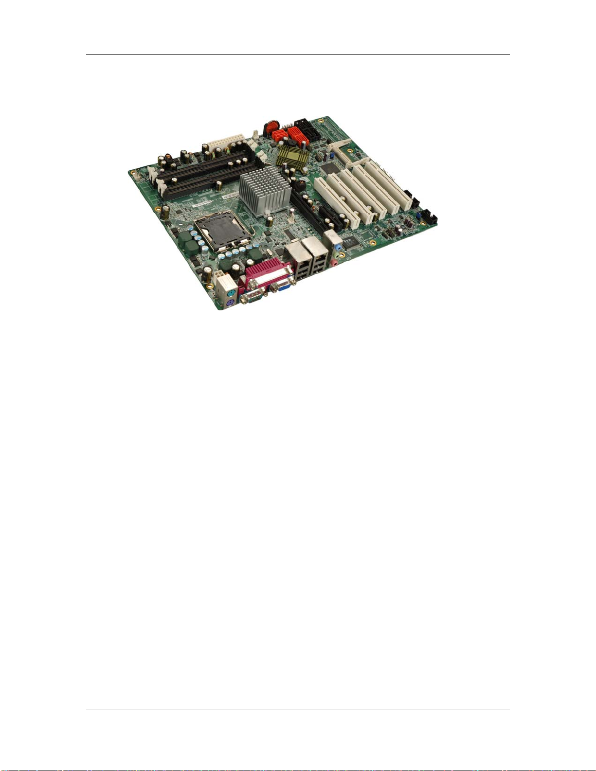
Figure 1-1: MXGD Motherboard
The MXGD ATX form factor motherboard is a LGA775 Intel® Core™2 Quad, Core™2
Duo, Pentium® D, Pentium® 4 or Celeron® D platform with a 533 MHz, 800 MHz or
1066 MHz front side bus (FSB). Up to 8.0 GB of DDR2 SDRAM and up to six SATA II hard
disk drives (HDD) are supported. High-performance PCI Express (PCIe) Gigabit Ethernet
(GbE) connectivity is integrated into the system. One PCIe x16, one PCIe x4, five PCI
slots and eight USB 2.0 connectors (four external and four internal) provide flexible
expansion options. Added system security is provided with Trusted Platform Module (TPM
v1.2) support.
1.1.1 MXGD Features
Some of the MXGD features are listed below.
Supports LGA775 Intel® CPUs including:
o Intel® Core™2 Quad
o Intel® Core™2 Duo
o Intel® Pentium® D
o Intel® Pentium® 4
o Intel® Celeron® D
2 ©Copyright 2009 CyberResearch, Inc.
Page 23

CyberResearch® Motherboards MXGD Series
Maximum FSB of 1066 MHz
Supports four 240-pin 533 MHz, 667 MHz or 800 MHz 2.0 GB (max.) DDR2
memory modules
Added security with support for TPM v1.2
Expansion slots include:
o One PCIe x16 slot
o One PCIe x4 slot
o Five PCI slots
Six SATA II drives with transfer rates of 3.0Gb/s supp orted
Eight USB 2.0 devices supported
Dual PCIe GbE Ethernet connectors
PICMG 1.3 form factor
RoHS compliant
Supports ATX power supplies
1.2 MXGD Overview
1.2.1 MXGD Overview Photo
The MXGD has a wide variety of peripheral interface connectors. Figure 1-2 is a labeled
photo of the peripheral interface connectors on the MXGD.
CyberResearch, Inc. 3
25 Business Park Drive P: (203) 643-5000; F: (203) 643-5001
Branford, CT USA www.cyberresearch.com
Page 24
MXGD Series CyberResearch® Motherboards
Figure 1-2: MXGD Overview [Front View]
1.2.2 MXGD Peripheral Connectors and Jumpers
The MXGD has the following connectors on-board:
1 x ATX +12V power connector
1 x ATX power connector
1 x Audio connector
1 x CompactFlash® Type II (CF Type II) socket
1 x Digital input/output (DIO) connector
3 x Fan connectors
1 x Front panel connector
4 ©Copyright 2009 CyberResearch, Inc.
Page 25

CyberResearch® Motherboards MXGD Series
1 x Infrared interface connector
5 x PCI expansion slots
1 x PCIe x16 expansion slot
1 x PCIe x4 expansion slots
6 x Serial ATA II (SATA II) drive connectors
5 x Serial port connectors
1 x SPDIF connector
1 x SPI flash connector
1 x TPM connector
2 x USB 2.0 connectors (support four USB devices)
The MXGD has the following external peripheral interface connectors on the board rear
panel
3 x Audio jacks
2 x Ethernet connectors
1 x Parallel port connector
2 x PS/2 connectors
1 x Serial port connector
4 x USB 2.0 port connectors
1 x VGA connector
The MXGD has the following on-board jumpers:
Clear CMOS
CF card setting
Select RS-232/422/485 for COM2
COM3/COM4 Pin 8 Select
CyberResearch, Inc. 5
25 Business Park Drive P: (203) 643-5000; F: (203) 643-5001
Branford, CT USA www.cyberresearch.com
Page 26
MXGD Series CyberResearch® Motherboards
1.2.3 Technical Specifications
MXGD technical specifications are listed in Table 1-1. See Chapter 2 for details.
Specification MXGD
Form Factor
System CPU
Front Side Bus
System Chipset
Memory
ATX
LGA775 Intel® Core™ 2 Quad
LGA775 Intel® Core™ 2 Duo
LGA775 Intel® Pentium® D
LGA775 Intel® Pentium® 4
LGA775 Intel® Celeron® D
533 MHz, 800 MHz or 1066 MHz
Northbridge: Intel® Q965
Southbridge: Intel® ICH8DO
Four dual channel 240-pin DDR2 DIMM sockets supp ort
four 533 MHz, 667 MHz or 800 MHz 2.0 GB (max.) DIMM. A
maximum of 8.0 GB DDR2 is supported.
Display
BIOS
VGA integrated into the Intel® Q965
AMI Flash BIOS
7.1 channel HD audio kit with Realtek ALC883 and dual
Audio
audio streams supported
TPM
One 20-pin connector TPM v1.2 module
One PCIe x16 slot
Expansion Options
One PCIe x4 slots
Five PCI slots
Infrared (IrDA)
One IrDA by pin header
6 ©Copyright 2009 CyberResearch, Inc.
Page 27
CyberResearch® Motherboards MXGD Series
Dual Broadcom BCM5787M PCIe GbE chipsets with ASF
LAN
2.0 support
SuperIO
SSD
Digital I/O
COM
USB 2.0
IDE
SATA
Keyboard/mouse
Parallel Port
ITE IT8712F
CF Type II
8-bit digital I/O, 4-bit input/4-bit output
Five RS-232 serial ports (four internal, one external)
One RS-232, RS-422 or RS-485 serial port (internal)
Eight USB 2.0 devices supported
Two 40-pin IDE connector connects to two Ultra
ATA33/66/100 devices
Six 3.0 Gbps SATA II drives supported
Two PS/2 connectors for keyboard and mouse
One external parallel port connects to parallel
communications device (e.g. printer)
Watchdog Timer
Power Supply
Software programmable 1-255 sec. by super I/O
ATX power only
5 V @ 4.62 A, 12 V @ 9.71 A and 3.3 V @ 5.74z A
Power Consumption
(Intel® Pentium® 4 3.73GHz, 1066MHz FSB CPU and 1GB
667MHz DDR2)
Temperature
Humidity (operating)
Dimensions (LxW)
Weight (GW/NW)
0ºC – 60ºC (32ºF - 140ºF)
5%~95% non-condensing
304.80 mm x 243.84 mm
1350g/750g
Table 1-1: Technical Specifications
CyberResearch, Inc. 7
25 Business Park Drive P: (203) 643-5000; F: (203) 643-5001
Branford, CT USA www.cyberresearch.com
Page 28

MXGD Series CyberResearch® Motherboards
Intentionally Blank
8 ©Copyright 2009 CyberResearch, Inc.
Page 29

CyberResearch® Motherboards MXGD Series
Chapter
2
2 Detailed Specifications
CyberResearch, Inc. 9
25 Business Park Drive P: (203) 643-5000; F: (203) 643-5001
Branford, CT USA www.cyberresearch.com
Page 30

MXGD Series CyberResearch® Motherboards
2.1 Dimensions
2.1.1 Board Dimensions
The dimensions of the board are listed below:
Length: 304.80mm
Width: 243.84mm
Figure 2-1: MXGD Dimensions (mm)
2.1.2 External Interface Panel Dimensions
External peripheral interface connector panel dimensions are shown in Figure 2-2.
10 ©Copyright 2009 CyberResearch, Inc.
Page 31

CyberResearch® Motherboards MXGD Series
Figure 2-2: External Interface Panel Dimensions (mm)
2.2 Data Flow
Figure 2-3 shows the data flow between the two on-board chip set s and other components
installed on the motherboard and described in the following se ctions of this chapter.
CyberResearch, Inc. 11
25 Business Park Drive P: (203) 643-5000; F: (203) 643-5001
Branford, CT USA www.cyberresearch.com
Page 32

MXGD Series CyberResearch® Motherboards
Figure 2-3: Data Flow Block Diagram
12 ©Copyright 2009 CyberResearch, Inc.
Page 33

CyberResearch® Motherboards MXGD Series
2.3 Compatible Processors
The MXGD supports the following LGA775 processors:
Intel® Core™2 Quad
Intel® Core™2 Duo
Intel® Pentium® D
Intel® Pentium® 4
Intel® Celeron® D
All of the above processors are interfaced with an Intel® Q965 northbridge chipset through
the front side bus (FSB). Features of the supported processors are listed in sections
below.
2.3.1 Intel® Core™2 Quad Features
Intel® Core™2 Quad features include:
Four processing cores
Up to 8MB of shared L2 cache
Up to 1066 MHz FSB
Intel® Wide Dynamic Execution
Intel® Intelligent Power Capability
Intel® Smart Memory Access
Intel® Advanced Smart Cache
Intel® Advanced Digital Media Boost
2.3.2 Intel® Core™2 Duo Features
Intel® Core™2 Duo features include:
Two processing cores
Up to 8MB of shared L2 cache
Up to 1066 MHz FSB
Intel® Wide Dynamic Execution
Intel® Intelligent Power Capability Intel® Smart Memory Access
CyberResearch, Inc. 13
25 Business Park Drive P: (203) 643-5000; F: (203) 643-5001
Branford, CT USA www.cyberresearch.com
Page 34

MXGD Series CyberResearch® Motherboards
Intel® Advanced Smart Cache
Intel® Advanced Digital Media Boost
2.3.3 Intel® Pentium® 4 Features
Intel® Pentium® 4 features include:
Hyper-Threading Technology
Enhanced Intel SpeedStep® Technology
Intel® Extended Memory 64 Technology
Execute Disable Bit
2.3.4 Intel® Pentium® D Features
Intel® Pentium® D features include:
Dual core processing improves performance and multimedia management
Intel® Visualization Technology
Dual 2MB level 2 cache
800MHz FSB
Execute Disable Bit
Intel® Extended Memory 64 Technology
Enhanced Intel SpeedStep® Technology
Streaming SIMD sol ution s
2.3.5 Intel® Celeron® D Features
Intel® Celeron® D features include:
Intel® Extended Memory 64 Technology
512KB Level 2 cache
533MHz FSB
Execute Disable Bit
Streaming SIMD sol ution s
14 ©Copyright 2009 CyberResearch, Inc.
Page 35

CyberResearch® Motherboards MXGD Series
2.4 Intel® Q965 Northbridge Chipset
2.4.1 Intel® Q965 Overview
The Intel® Q965 (G)MCH supports LGA775 processors. The (G)MCH supports a FSB
frequency of 533 MHz, 800 MHz or 1066 MHz. Some of the features of the Intel® Q965
(G)MCH Include:
Support for the following processors.
o Intel® Core™2 Quad
o Intel® Core™2 Duo
o Intel® Pentium® D
o Intel® Pentium® 4
o Intel® Celeron® D
Supports Hyper-Threading Technology (HT Technology)
Supports FSB Dynamic Bus Inversion (DBI)
Supports 36-bit host bus addressing, allowing the processor to access the
entire
64 GB of the (G)MCH’s memory address space
Has a 12-deep In-Order Queue to support up to twelve outstanding pipelined
address requests on the host bus
Has a 1-deep Defer Queue
Uses GTL+ bus driver with integrated GTL termination resistors
Supports a Cache Line Size of 64 bytes
2.4.2 Intel® Q965 Memory Support
WARNING:
Only DDR2 memory module can be installed on the MXGD. Do not
install DDR memory modules. If a DDR memory module is installed on
the MXGD, the MXGD may be irreparably damaged.
The Intel® Q965 supports up to four 2GB DDR2 DIMMs with the following specifications:
CyberResearch, Inc. 15
25 Business Park Drive P: (203) 643-5000; F: (203) 643-5001
Branford, CT USA www.cyberresearch.com
Page 36

MXGD Series CyberResearch® Motherboards
Only un-buffered DIMMs supported
DDR2 only
Maximum supported bandwidth (assuming DDR2 800 MHz):
o Single-channel: 6.4 GB/s
o Dual-channel asymmetric mode: 6.4 GB/s
o Dual-channel interleaved mode: 12.8 GB/s
Capacities of 256MB, 512MB, 1GB or 2GB
Transfer speeds of 533MHz, 667MHz or 800MHz
The memory sockets are shown in Figure 2-4.
Figure 2-4: 240-pin DIMM Sockets
16 ©Copyright 2009 CyberResearch, Inc.
Page 37

CyberResearch® Motherboards MXGD Series
2.4.2.1 Intel® Q965 Analog CRT Support
A DB-15 VGA connector on the external peripheral interface connector panel is interfaced
to the Intel® Q965 graphics engine. The Intel® Q965 internal graphics engine, with an
400MHz integrated 24-bit RAMDAC. Some of the graphics features are listed below.
Analog Display Support
400 MHz Integrated 24-bit RAMDAC
Up to 2048x1536 @ 75 Hz refresh
Hardware Color Cursor Support
DDC2B Compliant Interface
2.4.3 Intel® Q965 PCIe x16
2.4.3.1 PCIe x16 Bus Overview
The Intel® Q965 northbridge has one 16-lane PCIe port that is intended for an external
PCIe graphics card. The PCIe x16 graphics card is installed on the PCIe x16 slot (Figure
2-5) and interfaced to the northbridge directly.
CyberResearch, Inc. 17
25 Business Park Drive P: (203) 643-5000; F: (203) 643-5001
Branford, CT USA www.cyberresearch.com
Page 38

MXGD Series CyberResearch® Motherboards
Figure 2-5: PCIe x16 Expansion Slot
2.4.3.2 PCIe x16 Bus Specifications
The PCIe port is compliant with the PCI Express* Base Specification revision 1.1. The
PCIe x16 port operates at a frequency of 2.5 Gb/s on each lane while employing 8b/10b
encoding; the port supports a maximum theoretical bandwidth of 40 Gb/s in each
direction. Some of the features are listed below.
One, 16-lane PCIe port intended for graphics attach, compatible to the PCI
Express* Base Specification revision 1.1a.
PCI Express frequency of 1.25 GHz resulting in 2.5 Gb/s each direction
Raw bit-rate on the data pins of 2.5 Gb/s results in a real bandwidth per pair of
250 MB/s given the 8b/10b encoding used to transmit data across this
interface
Maximum theoretical realized bandwidth on the interface of 4 GB/s in each
18 ©Copyright 2009 CyberResearch, Inc.
Page 39

CyberResearch® Motherboards MXGD Series
direction simultaneously, for an aggregate of 8 GB/s when x16.
PCI Express* Graphics Extended Configuration Space. The first 256 bytes of
configuration space alias directly to the PCI Compatibility configuration space.
The remaining portion of the fixed 4-KB block of memory-mapped space
above that (starting at 100h) is known as extended configuration space.
PCI Express Enhanced Addressing Mechanism. Accessing the device
configuration pace in a flat memory mapped fashion.
Automatic discovery, negotiation, and training of link out of reset
Supports traditional PCI style traffic (asynchronous snooped, PCI ordering)
Supports traditional AGP style traffic (asynchronous non-snooped, PCI
Express relaxed ordering)
Hierarchical PCI-compliant configuration mechanism for downstream devices
(i.e., normal PCI 2.3 Configuration space as a PCI-to-PCI bridge)
Supports “static” lane numbering reversal. This method of lane reversal is
controlled by a Hardware Reset strap, and reverses both the receivers and
transmitters for all lanes (e.g., TX[15]->TX[0], RX[15]->RX[0]). This method is
transparent to all external devices and is different than lane reversal as
defined in the PCI Express Specification. In particular, link initialization is not
affected by static lane reversal.
2.4.4 Intel® Q965 Direct Media Interface (DMI)
Intel® Q965 northbridge GMCH is connected to the Intel® ICH8DO Southbridge Chipset
through the chip-to-chip Direct Media Interface (DMI). Features of the Intel
listed below:
chip-to-chip connection interface to Intel ICH8
2GB/s (1GB/s in each direction) bus speed
32-bit downstream address
100 MHz reference clock (shared with PCI Express Graphics Attach)
APIC and MSI interrupt messaging support
®
Q965 DMI are
Message Signaled Interrupt (MSI) messages
SMI, SCI and SERR error indication
DMA, floppy drive, and LPC bus master
CyberResearch, Inc. 19
25 Business Park Drive P: (203) 643-5000; F: (203) 643-5001
Branford, CT USA www.cyberresearch.com
Page 40

MXGD Series CyberResearch® Motherboards
Figure 2-6: DMI Interface
2.5 Intel® ICH8DO Southbridge Chipset
2.5.1 Intel® ICH8DO Overview
The Intel® ICH8DO southbridge chipset is connected to the Intel® Q965 northbridge
GMCH through the chip-to-chip Direct Media Interface (DMI). Some of the features of the
Intel® ICH8DO are listed below.
Complies with PCI Express Base Specification, Revision 1.1
Complies with PCI Local Bus Spe cificati on, Revision 2.3 and su pports 33MHz
PCI operations
Supports ACPI Power Management Logic
Contains:
o Enhanced DMA controller
20 ©Copyright 2009 CyberResearch, Inc.
Page 41

CyberResearch® Motherboards MXGD Series
o Interrupt controller
o Timer functions
Integrated SATA host controller with DMA operations and AHCI su pport
interfaced to six SA TA connectors on the MXGD
Supports the eight USB 2.0 devices on the MXGD with five UHCI controllers
and two EHCI controllers
Integrated 10/100/1000 GbE MAC with System Defense
Complies with System Management Bus (SMBus) Specification, Version 2.0
Supports Intel High Definition Audio
Supports Intel® Matrix Storage Technology
Supports Intel® Active Management Technology (ICH8DO only)
Low Pin Count (LPC) interface
Firmware Hub (FWH) interface support
Serial Peripheral Interface (SPI) support
2.5.2 SPI BIOS Chipset:
A licensed copy of AMI BIOS installed is an onboard SPI (Serial Peripheral Interface)
BIOS chipset. Some of the BIOS features are listed below:
AMI Flash BIOS
SMIBIOS (DMI) compliant
Console redirection function support
PXE (Pre-boot Execution Environment) support
USB booting support
CyberResearch, Inc. 21
25 Business Park Drive P: (203) 643-5000; F: (203) 643-5001
Branford, CT USA www.cyberresearch.com
Page 42

MXGD Series CyberResearch® Motherboards
Figure 2-7: SPI BIOS Chipset
2.5.3 Intel® High Definition Audio
The MXGD onboard audio connector can connect to an optional audio kit. The codec on
the optional audio kit is connected to the ICH8DO controller through the Intel® High
Definition Audio serial link. The DMA engines in the controller move samples of digitally
encoded data between system memory and the audio kit codec.
22 ©Copyright 2009 CyberResearch, Inc.
Page 43

CyberResearch® Motherboards MXGD Series
Figure 2-8: Audio Connectors
2.5.4 Intel® ICH8DO Low Pin Count (LPC) Interface
The ICH8DO LPC interface complies with the LPC 1.1 specifications. The LPC bus from
the ICH8DO is connected to the following components:
BIOS chipset
Super I/O chipset
2.5.5 Intel® ICH8DO PCI Interface
The PCI interface on the ICH8DO is compliant with the PCI Revision 2.3 implementation.
Some of the features of the PCI interface are listed below.
PCI Revision 2.3 compliant
33MHz
CyberResearch, Inc. 23
25 Business Park Drive P: (203) 643-5000; F: (203) 643-5001
Branford, CT USA www.cyberresearch.com
Page 44

MXGD Series CyberResearch® Motherboards
5V tolerant PCI signals (except PME#)
Integrated PCI arbiter supports up to seven PCI bus masters
Five PCI channels are connected to five PCI expansion sockets.
Figure 2-9: PCI Expansion Slots
2.5.6 Intel® ICH8DO PCIe Ports
There are six root PCIe ports on the Intel® ICH8DO. Port 5 and port 6 provides PCIe x1
connectivity to two Broadcom PCIe GbE controllers. Port 1 to port 4 are connected to a
PCIe x4 expansion slot.
24 ©Copyright 2009 CyberResearch, Inc.
Page 45

CyberResearch® Motherboards MXGD Series
2.5.7 Intel® ICH8DO Real Time Clock
256 bytes of battery backed RAM is provided by the Motorola MC146818A real time clock
(RTC) integrated into the ICH8DO. The RTC operates on a 3V battery and 32.768KHz
crystal. The RTC keep s track of the time and stores system data even when the system is
turned off.
2.5.8 Intel® ICH8DO SATA Controller
The two integrated SATA controllers on the ICH8DO southbridge support six SATA II
drives on the MXGD with independent DMA operations. The SATA controller contains two
modes of operation – a legacy mode using I/O space, and an AHCI mode using memory
space. SATA controller specifications are listed below.
Supports independent DMA operation on up to six ports
Supports six SATA drive s
Supports 3Gb/s data transfer speeds
Supports Serial ATA 1.0 Specification, Revision 1.0
CyberResearch, Inc. 25
25 Business Park Drive P: (203) 643-5000; F: (203) 643-5001
Branford, CT USA www.cyberresearch.com
Page 46

MXGD Series CyberResearch® Motherboards
Figure 2-10: SATA Connectors
2.5.9 Intel® ICH8DO USB Controller
Up to eight high-speed, full-speed or low-speed USB devices are supported by the
ICH8DO on the MXGD. High-speed USB 2.0, with data transfers of up to 480MB/s, is
enabled with the ICH8DO integrated Enhanced Host Controller Interface (EHCI) compliant
host controller. USB full-speed and low-speed signaling is supported by the ICH8DO
integrated Universal Host Controller Interface (UHCI) controllers.
26 ©Copyright 2009 CyberResearch, Inc.
Page 47

CyberResearch® Motherboards MXGD Series
Figure 2-11: USB Connector
2.6 Intel® ICH8DO PCIe Bus Components
2.6.1 PCIe Bus Overview
The MXGD Intel® ICH8DO southbridge PCIe bus is split into two PCIe x1 channels and
one PCIe x4 channel. The two PCIe x1 channels are each connecte d to a Broadcom PCIe
GbE controller. The PCIe x4 channel is connected to a PCIe x4 slot.
2.6.2 PCIe x4 Expansion
Four of the PCI express root ports are connected to a single PCIe x4 expansion slot
enabling PCIe x4 cards to be installed on the system.
CyberResearch, Inc. 27
25 Business Park Drive P: (203) 643-5000; F: (203) 643-5001
Branford, CT USA www.cyberresearch.com
Page 48

MXGD Series CyberResearch® Motherboards
Figure 2-12: PCIe x4 Expansion Slot
2.6.3 PCIe GbE Ethernet
Two PCIe x1 lanes from the are connected to two Broadcom BCM5787M PCIe GbE
controllers shown in Figure 2-13 below.
28 ©Copyright 2009 CyberResearch, Inc.
Page 49

CyberResearch® Motherboards MXGD Series
Figure 2-13: Broadcom PCI GbE Controllers
The Broadcom BCM5787M is a 10/100/1000BASE-T Ethernet LAN controller. The
BCM5787M combines a triple-speed IEEE 802.3 compliant Media Access Controller
(MAC) with a triple-speed Ethernet transceiver, a PCIe bus interface, and an on-chip
buffer memory. Some of the BCM5787 controller features are listed below:
Integrated 10/100/1000BASE-T transceiver
Automatic MDI crossover function
PCIe v1.0a
10/100/1000BASE-T full/half-duplex MAC
Wake on LAN support meeting the ACPI requirements
Statistics for SNMP MIB II, Ethernet-like MIB, and Ethernet MIB (802.3z,
clause 30)
Serial EEPROM or serial flash support
CyberResearch, Inc. 29
25 Business Park Drive P: (203) 643-5000; F: (203) 643-5001
Branford, CT USA www.cyberresearch.com
Page 50

MXGD Series CyberResearch® Motherboards
2.7 LPC Bus Components
2.7.1 LPC Bus Overview
The LPC bus is connected to components listed belo w:
Super I/O chipset
Serial port chipset
Figure 2-14: LPC Bus Components
2.7.2 Super I/O chipset
The iTE IT8712F Super I/O chipset is connected to the ICH8DO southbridge through the
LPC bus. The iTE IT8712F is an LPC interface-based Super I/O device that comes with
30 ©Copyright 2009 CyberResearch, Inc.
Page 51

CyberResearch® Motherboards MXGD Series
Environment Controller integration. Some of the features of the iTE IT8712F chipset are
listed below:
PC98/99/2001, ACPI and LANDesk Compliant
Enhanced Hardware Monitor
Fan Speed Controller
Single +5V Power Supply
Two 16C550 UARTs for serial port control
One IEEE 1284 Parallel Port
Keyboard Controller
Watchdog T i mer
Serial IRQ Support
Vbat & Vcch Support
Single +5V Power Supply
Some of the Super I/O features are described in more detail below:
2.7.2.1 Super I/O LPC Interface
The LPC interface on the Super I/O complies with the Intel® Low Pin Count Specification
Rev. 1.0. The LPC interface supports both LDRQ# and SERIRQ protocols as well as PCI
PME# interfaces.
2.7.2.2 Super I/O 16C550 UARTs
The onboard Super I/O has two integrated 16C550 UARTs that can support the following:
Two standard serial ports (COM1 and COM2)
IrDa 1.0 and ASKIR protocols
Another two chipsets connected to the LPC bus provided connectivity to another two seri al
port connectors (COM3 and COM4).
CyberResearch, Inc. 31
25 Business Park Drive P: (203) 643-5000; F: (203) 643-5001
Branford, CT USA www.cyberresearch.com
Page 52

MXGD Series CyberResearch® Motherboards
2.7.2.3 Super I/O Enhanced Hardware Monitor
The Super I/O Enhanced Hardware Monitor monitors three thermal inputs, VBAT
internally, and eight voltage monitor inputs. These hardware parameters are reported in
the BIOS and can be read from the BIOS Hardware Health Configuration menu.
2.7.2.4 Super I/O Fan Speed Controller
The Super I/O fan speed controller enables the system to monitor the speed of the fan.
One of the pins on the fan connector is reserved for fan speed detection and interfaced to
the fan speed controller on the Super I/O. The fan speed is then reported in the BIOS.
2.7.2.5 Super I/O Keyboard Controller
The Super I/O keyboard controller can execute the 8042 instruction set. Some of the
keyboard controller features are listed below:
The 8042 instruction is compatible with a PS/2 keyboard and PS/2 mouse
Gate A20 and Keyboard re set output
Supports multiple keyboard power on events
Supports mouse double-click and/or mouse move power on events
2.7.3 Serial Port Chipset
The MXGD has a Fintek F81216DG chipset onboard enables the addition of four
additional UART serial ports (COM3, COM4, COM5 and COM6). UART includes 16-byte
send/receive FIFO. The Fintek serial port chipset is interfaced to the southbridge chipset
through the LPC bus. Some of the features of the Fintek chipset are listed below:
Supports LPC interface
Totally provides 4 UART (16550 asynchronous) ports
o 3 x Pure UART
o 1 x UART+IR
One Watch dog timer with WDTOUT# signal
One Frequency input 24/48MHz
Powered by 3Vcc
32 ©Copyright 2009 CyberResearch, Inc.
Page 53

CyberResearch® Motherboards MXGD Series
2.8 Environmental and Power Specifications
2.8.1 System Monitoring
Three thermal inputs on the MXGD Super I/O Enhanced Hardware Monitor monitor the
following temperatures:
Temperature sensor 1
Temperature sensor 2
Temperature sensor 3
All three fan speeds are monitored and can be seen in the BIOS as:
FAN1 Speed
FAN2 Speed
FAN3 Speed
Eight voltage inputs on the MXGD Super I/O Enhanced Hardware Monitor monitor the
following volatages:
Vcore
Vcc
+3.30V
+5.00V
+12.0V
+1.2V
+1.5V
+1.25V
VBAT
The MXGD Super I/O Enhanced Hardware Monitor also monitors the following voltages
internally:
VBAT
The values for the above environmental parameters are all recorded in the BIOS
Hardware Health Configuration menu.
CyberResearch, Inc. 33
25 Business Park Drive P: (203) 643-5000; F: (203) 643-5001
Branford, CT USA www.cyberresearch.com
Page 54

MXGD Series CyberResearch® Motherboards
2.8.2 Operating Temperature and Temperature Control
The maximum and minimum operating temperatures for the MXGD are listed below.
Minimum Operating Temperature: 0ºC (32°F)
Maximum Operating Temperature: 60°C (140°F)
A cooling fan and heat sink must be installed on the CPU. Thermal paste must be
smeared on the lower side of the heat sink before it is mounted on the CPU. Heat sinks
are also mounted on the northbridge and southbridge chipsets to ensure the operating
temperature of these chips remain low.
2.8.3 Power Consumption
Ta b l e 2 - 1 shows the power consumption parameters for the MXGD running with a 1066
MHz FSB 3.73 GHz Intel® Pentium® 4 processor with 1 GB of 667 MHz DDR2 memory.
Voltage Current
+3.3 V 5.74 A
+5 V 4.62 A
+12 V 9.71 A
Table 2-1: Power Consumption
34 ©Copyright 2009 CyberResearch, Inc.
Page 55

CyberResearch® Motherboards MXGD Series
Chapter
3
3 Unpacking
CyberResearch, Inc. 35
25 Business Park Drive P: (203) 643-5000; F: (203) 643-5001
Branford, CT USA www.cyberresearch.com
Page 56

MXGD Series CyberResearch® Motherboards
3.1 Anti-static Precautions
WARNING:
Failure to take ESD precautions during the installation of the MXGD
may result in permanent damage to the MXGD and severe injury to the
user.
Electrostatic discharge (ESD) can cause serious damage to electronic components,
including the MXGD. Dry climates are especially susceptible to ESD. It is therefore critical
that whenever the MXGD, or any other electrical component is handled, the following
anti-static precautions are strictly adhered to.
Wear an anti-static wristband: - Wearing a simple anti-static wristband can
help to prevent ESD from damaging the board.
Self-grounding:- Before handling the board touch any grounded conducting
material. During the time the board is handled, frequently touch any
conducting materials that are connected to the ground.
Use an anti-static pad: When configuring the MXGD, place it on an
antic-static pad. This reduces the possibility of ESD damaging the MXGD.
Only handle the edges of the PCB:-: When handling the PCB, hold the PCB
by the edges.
3.2 Unpacking
3.2.1 Unpacking Precautions
When the MXGD is unpacked, please do the following:
Follow the anti-static precautions outlined in Section 3.1.
Make sure the packing box is facing upwards so the MXGD does not fall out
of the box.
Make sure all the components shown in Section 3.3 are present.
36 ©Copyright 2009 CyberResearch, Inc.
Page 57

CyberResearch® Motherboards MXGD Series
3.3 Unpacking Checklist
NOTE:
If some of the components listed in the checklist below are missing,
please do not proceed with the installation. Contact CyberResearch,
Inc.
3.3.1 Package Contents
The MXGD is shipped with the following components:
Quantity Item and Part Number Image
1 MXGD
2 Dual RS-232 cable
1 Single RS-232 cable
1 I/O Shielding
6 SATA cables
3 SATA power cables
CyberResearch, Inc. 37
25 Business Park Drive P: (203) 643-5000; F: (203) 643-5001
Branford, CT USA www.cyberresearch.com
Page 58

MXGD Series CyberResearch® Motherboards
1 Mini jumper Pack
1 Utility CD
Table 3-1: Package List Contents
38 ©Copyright 2009 CyberResearch, Inc.
Page 59

CyberResearch® Motherboards MXGD Series
3.4 Optional Items
2-port USB cable (w bracket)
4-port USB cable
CPU cooling kit
CPU cooling kit
Dual RS-232/422/485 cables
Table 3-2: Package List Contents
CyberResearch, Inc. 39
25 Business Park Drive P: (203) 643-5000; F: (203) 643-5001
Branford, CT USA www.cyberresearch.com
Page 60

MXGD Series CyberResearch® Motherboards
Intentionally Blank
40 ©Copyright 2009 CyberResearch, Inc.
Page 61

CyberResearch® Motherboards MXGD Series
Chapter
4
4 Connector Pinouts
CyberResearch, Inc. 41
25 Business Park Drive P: (203) 643-5000; F: (203) 643-5001
Branford, CT USA www.cyberresearch.com
Page 62

MXGD Series CyberResearch® Motherboards
4.1 Peripheral Interface Connectors
Section 4.1.2 shows peripheral interface connector locations. Section 4.1.2 lists all the
peripheral interface connectors seen in Section 4.1.2.
4.1.1 MXGD Layout
Figure 4-1 shows the on-board peripheral connectors, rear panel peripheral connectors
and on-board jumpers.
Figure 4-1: Connector and Jumper Locations
42 ©Copyright 2009 CyberResearch, Inc.
Page 63

CyberResearch® Motherboards MXGD Series
4.1.2 Peripheral Interface Connectors
Table 4-1 shows a list of the peripheral interface connectors on the MXGD. Detailed
descriptions of these connectors can be found below.
Connector Type Label
ATX +12V power connector 4-pin ATX ATX1
ATX power connector 24-pin ATX ATX2
Audio CD In 4-pin header CD_IN1
Audio connector 10-pin header CN3
Cooling fan connector, CPU 4-pin wafer IO_FAN2
Cooling fan connector , system 3-pin wafer IO_FAN1
Cooling fan connector , system 3-pin wafer IO_FAN3
Digital input/output connector 10-pin header DIO1
Front panel connector 14-pin header F_PANEL1
Infrared (IrDA) connector 5-pin header IR1
Serial ATA drive connector 7-pin SATA SATA1
Serial ATA drive connector 7-pin SATA SATA2
Serial ATA drive connector 7-pin SATA SATA3
Serial ATA drive connector 7-pin SATA SATA4
Serial ATA drive connector 7-pin SATA SATA5
Serial ATA drive connector 7-pin SATA SATA6
Serial port connector (COM2) 14-pin header COM2
Serial port connector (COM3) 10-pin header COM3
Serial port connector (COM4) 10-pin header COM4
CyberResearch, Inc. 43
25 Business Park Drive P: (203) 643-5000; F: (203) 643-5001
Branford, CT USA www.cyberresearch.com
Page 64

MXGD Series CyberResearch® Motherboards
Serial port connector (COM5) 10-pin header COM5
Serial port connector (COM6) 10-pin header COM6
SPDIF connector 5-pin header CN1
SPI connector 8-pin header CN4
TPM connector 20-pin header TPM1
USB connectors 8-pin header USB1
USB connectors 8-pin header USB2
Table 4-1: Peripheral Interface Connectors
4.1.3 External Interface Panel Connectors
Table 4-2 lists the rear panel connectors on the MXGD. Detailed descriptions of these
connectors can be found in Section 4.3 on page 68
Connector Type Label
Audio connector 3 x audio jacks CN2
Keyboard and mouse connector Dual PS/2 KBMS1
Parallel port connector D-Sub 25-pin female 3IN1 DSUB1
Serial port connector (RS-232) D-Sub 9-pin male 3IN1 DSUB1
Dual USB and LAN Combo Dual USB ports and RJ-45 USB_LAN1
Dual USB and LAN Combo Dual USB ports and RJ-45 USB_LAN2
VGA port con nector D-Sub 15-pin female 3IN1 DSUB1
Table 4-2: Rear Panel Connectors
44 ©Copyright 2009 CyberResearch, Inc.
Page 65

CyberResearch® Motherboards MXGD Series
4.2 Internal Peripheral Connectors
Internal peripheral connectors are found on the motherboard and are only accessible
when the motherboard is outside of the chassis. Thi s section ha s complete description s of
all the internal, peripheral connectors on the MXGD.
4.2.1 ATX +12V Power Connector
CN Label:
CN Type:
ATX1
4-pin ATX power connector (2x2)
CN Location: See Figure 4-2
CN Pinouts: See Table 4-3
The 4-pin ATX power connector is connected to an ATX power supply.
Figure 4-2: ATX Power Connector Location
PIN NO. DESCRIPTION
1 GND
2 GND
3 +12V
4 +12V
Table 4-3: ATX Power Connector Pinouts
CyberResearch, Inc. 45
25 Business Park Drive P: (203) 643-5000; F: (203) 643-5001
Branford, CT USA www.cyberresearch.com
Page 66

MXGD Series CyberResearch® Motherboards
4.2.2 ATX Power Connector
CN Label:
CN Type:
ATX2
24-pin A TX (2x12)
CN Location: See Figure 4-3
CN Pinouts: See Table 4-4
The ATX connector is connected to an external ATX power supply. Power is provided to
the system, from the power supply through this connector.
Figure 4-3: ATX Power Connector Pinout Locations
PIN NO. DESCRIPTION PIN NO. DESCRIPTION
1 +3.3V 13 +3.3V
2 +3.3V 14 -12V
3 GROUND 15 GROUND
4 +5V 16 PS-ON
5 GROUND 17 GROUND
6 +5V 18 GROUND
46 ©Copyright 2009 CyberResearch, Inc.
Page 67

CyberResearch® Motherboards MXGD Series
7 GROUND 19 GROUND
8 POWER GOOD 20 GND
9 5VSB 21 +5V
10 +12V 22 +5V
11 +12V 23 +5V
12 +3.3V 24 GND
Table 4-4: ATX Power Connector Pinouts
4.2.3 Audio CD In Connector (4-pin)
CN Label: CD_IN1
CN Type:
10-pin header
CN Location: See Figure 4-4
CN Pinouts: See Table 4-5
The 4-pin audio CD in connector is connected to an external audio CD device for the input
and output of audio signals from a CD player to the system.
Figure 4-4: Audio CD In Connector Pinouts (4-pin)
CyberResearch, Inc. 47
25 Business Park Drive P: (203) 643-5000; F: (203) 643-5001
Branford, CT USA www.cyberresearch.com
Page 68

MXGD Series CyberResearch® Motherboards
PIN NO. DESCRIPTION
1 CD Signal (Left)
2 Ground
3 Ground
4 CD Signal (Right)
Table 4-5: Audio CD In Connector Pinouts
4.2.4 Audio Connector
CN Label:
CN Type:
CN Location:
CN Pinouts:
CN3
10-pin header (2x5)
See Figure 4-5
See Table 4-6
The 10-pin audio connector is connected to external audio devices including speakers and
microphones for the input and output of audio signals to and from the system.
Figure 4-5: Audio Connector Location (10-pin)
48 ©Copyright 2009 CyberResearch, Inc.
Page 69

CyberResearch® Motherboards MXGD Series
PIN NO. DESCRIPTION PIN NO. DESCRIPTION
1 MIC-L 2 GND
3 MIC-R 4 +5V
5 LINE OUT-R 6 PULL DOWN
7 LINE OUT SENSE 8 KEY
9 LINE OUT-L 10 PULL DOWN
Table 4-6: Audio Connector Pinouts
4.2.5 Digital Input/Output (DIO) Connector
CN Label:
CN Type:
CN Location:
CN Pinouts:
DIO1
10-pin header (2x5)
See Figure 4-6
See Table 4-7
The digital input/output connector is managed through a Super I/O chip. The DIO
connector pins are user programmable.
Figure 4-6: DIO Connector Connector Locations
PIN NO. DESCRIPTION PIN NO. DESCRIPTION
1 Ground 2 VCC
3 Input 0 4 Output 0
CyberResearch, Inc. 49
25 Business Park Drive P: (203) 643-5000; F: (203) 643-5001
Branford, CT USA www.cyberresearch.com
Page 70

MXGD Series CyberResearch® Motherboards
5 Input 1 6 Output 1
7 Input 2 8 Output 2
9 Input 3 10 Output 3
Table 4-7: DIO Connector Connector Pinouts
4.2.6 Fan Connector (+12V) (CPU Cooling Fan)
CN Label:
CN Type:
CN Location:
CN Pinouts:
IO_FAN2
4-pin wafer
See Figure 4-7
See Table 4-8
The CPU cooling fan connector provides a 12V, 500mA current to a CPU cooling fan. The
connector has a "rotation" pin to get rotation signals from fans and notify the system so the
system BIOS can recognize the fan speed. Please note that only specified fans can issue
the rotation signals.
Figure 4-7: +12V Fan Connector Location
50 ©Copyright 2009 CyberResearch, Inc.
Page 71

CyberResearch® Motherboards MXGD Series
PIN NO. DESCRIPTION
1 GND
2 +12V
3 Rotation Signal
4 Control
Table 4-8: +12V Fan Connector Pinouts
4.2.7 Fan Connector (+12V) (System Cooling Fans)
CN Label: IO_FAN1, IO_FAN3
CN Type:
3-pin header
CN Location: See Figure 4-7
CN Pinouts: See Table 4-8
Two system cooling fan connectors provide a 12V, 500mA current to two system cooling
fans. The connectors have a "rotation" pin to get rotation signals from fans and notify the
system so the system BIOS can recognize the fan speed. Please note that only specified
fans can issue the rotation signals.
CyberResearch, Inc. 51
25 Business Park Drive P: (203) 643-5000; F: (203) 643-5001
Branford, CT USA www.cyberresearch.com
Page 72

MXGD Series CyberResearch® Motherboards
Figure 4-8: +12V Fan Connector Location
PIN NO. DESCRIPTION
1 GND
2 +12V
3 Fan Speed Detect
Table 4-9: +12V Fan Connector Pinouts
4.2.8 Front Panel Connector (14-pin)
CN Label:
CN Type:
CN Location:
CN Pinouts:
F_PANEL1
14-pin header (2x7)
See Figure 4-9
See Table 4-10
The front panel connector connects to external switches and indicators to monitor and
controls the motherboard. These indicators and switches include:
52 ©Copyright 2009 CyberResearch, Inc.
Page 73

CyberResearch® Motherboards MXGD Series
Power LED
Speaker
Power button
Reset
HDD LED
Figure 4-9: Front Panel Connector Pinout Locations (14-pin)
FUNCTION PIN DESCRIPTION FUNCTION PIN DESCRIPTION
Power LED
Power
Button
1 LED+ 2 BUZZER3 N/C 4 N/C
5 GND 6 N/C
7 PWRBTSW9 PWRBTSW+ 10 N/C
11 IDE_LED+ 12 RESET- HDD LED
13 IDE_LED-
Buzzer
Reset
Table 4-10: Front Panel Connector Pinouts (14-pin)
4.2.9 Infrared Interface Connector (5-pin)
CN Label:
IR1
8 VCC
14 GND
CN Type:
5-pin header (1x5)
CyberResearch, Inc. 53
25 Business Park Drive P: (203) 643-5000; F: (203) 643-5001
Branford, CT USA www.cyberresearch.com
Page 74

MXGD Series CyberResearch® Motherboards
CN Location:
CN Pinouts:
See Figure 4-10
See Table 4-1 1
The infrared interface connector supports both Serial Infrared (SIR) and Amplitude Shift
Key Infrared (ASKIR) interfaces.
Figure 4-10: Infrared Connector Pinout Locations
PIN NO. DESCRIPTION
1 VCC
2 NC
3 IR-RX
4 GND
5 IR-TX
Table 4-11: Infrared Connector Pinouts
4.2.10 PCI Slot
CN Label: PCI1, PCI2, PCI3, PCI4, PCI5
CN Type:
CN Location: See Figure 4-11
CN Pinouts: See Table 4-12
The PCI slot enables a PCI expansion module to be connected to the board.
PCI Slot
54 ©Copyright 2009 CyberResearch, Inc.
Page 75

CyberResearch® Motherboards MXGD Series
Figure 4-11: PCI Slot Location
PIN NO. DESCRIPTION PIN NO. DESCRIPTION
A1 TRST B1 -12V
A2 +12V B2 TCK
A3 TMS B3 GND
A4 TDI B4 TDO
A5 +5V B5 +5V
A6 INTA B6 +5V
A7 INTC B7 INTB
A8 +5V B8 INTD
A9 RESERVED3 B9 PRSNT1
CyberResearch, Inc. 55
25 Business Park Drive P: (203) 643-5000; F: (203) 643-5001
Branford, CT USA www.cyberresearch.com
Page 76

MXGD Series CyberResearch® Motherboards
A10 +5V B10 RESERVED1
A11 RESERVED4 B11 PRSNT2
A12 GND B12 GND
A13 GND B13 GND
A14 3.3V_AUX B14 RESERVED2
A15 RST B15 GND
A16 +5V B16 CLK
A17 GNT B17 GND
A18 GND B18 REQ
A19 PME B19 +5V
A20 AD30 B20 AD31
A21 +3.3V B21 AD29
A22 AD28 B22 GND
A23 AD26 B23 AD27
A24 GND B24 AD25
A25 AD24 B25 +3.3V
A26 IDSEL B26 C/BE3
A27 +3.3V B27 AD23
A28 AD22 B28 GND
A29 AD20 B29 AD21
A30 GND B30 AD19
A31 AD18 B31 +3.3V
A32 AD16 B32 AD17
A33 +3.3V B33 C/BE2
A34 FRAME B34 GND
A35 GND B35 IRDY
A36 TRDY B36 +3.3V
A37 GND B37 DEVSEL
A38 STOP B38 GND
A39 +3.3V B39 LOCK
A40 SDONE B40 PERR
A41 SBO B41 +3.3V
56 ©Copyright 2009 CyberResearch, Inc.
Page 77

CyberResearch® Motherboards MXGD Series
A42 GND B42 SERR
A43 PAR B43 +3.3V
A44 AD15 B44 C/BE1
A45 +3.3V B45 AD14
A46 AD13 B46 GND
A47 AD11 B47 AD12
A48 GND B48 AD10
A49 AD9 B49 GND
A52 C/BE0 B52 AD8
A53 +3.3V B53 AD7
A54 AD6 B54 +3.3V
A55 AD4 B55 AD5
A56 GND B56 AD3
A57 AD2 B57 GND
A68 AD0 B68 AD1
A59 +5V B59 +5V
A60 REQ64 B60 ACK64
A61 +5V B61 +5V
A62 +5V
B62 +5V
Table 4-12: PCI Slot
4.2.11 PCI Express x4 Slot
CN Label: PCIE4X_1
CN Type:
CN Location:
CN Pinouts:
64-pin PCIe x4 slots
See Figure 4-12
See Table 4-13
PCIe x4 expansion devices can be inserted into the PCIe x4 slots.
CyberResearch, Inc. 57
25 Business Park Drive P: (203) 643-5000; F: (203) 643-5001
Branford, CT USA www.cyberresearch.com
Page 78

MXGD Series CyberResearch® Motherboards
Figure 4-12: PCIe x4 Connector Locations
SIDE A SIDE B
PIN NAME PIN NAME PIN NAME PIN NAME
A1 N/C A2 +12V B1 +12V B2 +12V
A3 +12V A4 GND B3 +12V B4 GND
A5 N/C A6 N/C B5 SMCLK B6 SMDAT
A7 N/C A8 N/C B7 GND B8 +3.3V
A9 +3.3V A10 +3.3V B9 N/C B10 3.3V
A11 RESET A12 GND B11 WAKE# B12 N/C
A13 REFCLK+ A14 REFCLK- B13 GND B14 HSOp(0)
A15 GND A16 HSIp(0) B15 HSOn(0) B16 GND
A17 HSIn(0) A18 GND B17 N/C B18 GND
A19 N/C A20 GND B19 HSOp(1) B20 HSOn(1)
A21 HSIp(1) A22 HSIn(1) B21 GND B22 GND
A23 GND A24 GND B23 HSOp(2) B24 HSOn(2)
A25 HSIp(2) A26 HSIn(2 B25 GND B26 GND
A27 GND A28 GND B27 HSOp(3) B28 HSOn(3)
58 ©Copyright 2009 CyberResearch, Inc.
Page 79

CyberResearch® Motherboards MXGD Series
A29 HSIp(3) A30 HSIn(3) B29 GND B30 N/C
A31 GND A32 N/C B31 N/C B32 GND
Table 4-13: PCIe x4 Pinouts
4.2.12 PCI Express x16 Slot
CN Label: PCIE_1
CN Type:
CN Location:
164-pin PCIe x16 slot
See Figure 4-23
CN Pinouts: See Table 4-14 (Side A) Table 4-15 (Side B)
PCIe x16 expansion devices can be inserted into the PCIe x16 slot.
CyberResearch, Inc. 59
25 Business Park Drive P: (203) 643-5000; F: (203) 643-5001
Branford, CT USA www.cyberresearch.com
Page 80

MXGD Series CyberResearch® Motherboards
Figure 4-13: PCIe x16 Connector Location
PIN NAME PIN NAME PIN NAME PIN NAME
A1 Name A22 HSIn(1) A43 HSIp(6) A64 HSIp(11)
A2 PRSNT#1 A23 GND A44 HSIn(6) A65 HSIn(11)
A3 +12v A24 GND A45 GND A66 GND
A4 +12v A25 HSIp(2) A46 GND A67 GND
A5 GND A26 HSIn(2) A47 HSIp(7) A68 HSIp(12)
A6 JTAG2 A27 GND A48 HSIn(7) A69 HSIn(12)
A7 JTAG3 A28 GND A49 GND A70 GND
A8 JTAG4 A29 HSIp(3) A50 RSVD A71 GND
A9 JTAG5 A30 HSIn(3) A51 GND A72 HSIp(13)
A10 +3.3v A31 GND A52 HSIp(8) A73 HSIn(13)
A11 +3.3v A32 RSVD A53 HSIn(8) A74 GND
A12 PWRGD A33 RSVD A54 GND A75 GND
A13 GND A34 GND A55 GND A76 HSIp(14)
A14 REFCLK+ A35 HSIp(4) A56 HSIp(9) A77 HSIn(14)
A15 REFCLK- A36 HSIn(4) A57 HSIn(9) A78 GND
A16 GND A37 GND A58 GND A79 GND
A17 HSIp(0) A38 GND A59 GND A80 HSIp(15)
A18 HSIn(0) A39 HSIp(5) A60 HSIp(10) A81 HSIn(15)
A19 GND A40 HSIn(5) A61 HSIn(10) A82 GND
A20 RSVD A41 GND A62 GND
60 ©Copyright 2009 CyberResearch, Inc.
Page 81

CyberResearch® Motherboards MXGD Series
A21 GND A42 GND A63 GND
Table 4-14: PCIe x16 Side A Pinouts
PIN NAME PIN NAME PIN NAME PIN NAME
B1 +12v B22 GND B43 GND B64 GND
B2 +12v B23 HSOp(2) B44 GND B65 GND
B3 RSVD B24 HSOn(2) B45 HSOp(7) B66 HSOp(12)
B4 GND B25 GND B46 HSOn(7) B67 HSOn(12)
B5 SMCLK B26 GND B47 GND B68 GND
B6 SMDAT B27 HSOp(3) B48 PRSNT#2 B69 GND
B7 GND B28 HSOn(3) B49 GND B70 HSOp(13)
B8 +3.3v B29 GND B50 HSOp(8) B71 HSOn(13)
B9 JTAG1 B30 RSVD B51 HSOn(8) B72 GND
B10 3.3Vaux B31 PRNT#2 B52 GND B73 GND
B11 WAKE# B32 GND B53 GND B74 HSOp(14)
B12 RSVD B33 HSOp(4) B54 HSOp(9) B75 HSOn(14)
B13 GND B34 HSOn(4) B55 HSOn(9) B76 GND
B14 HSOp(0) B35 GND B56 GND B77 GND
B15 HSOn(0) B36 GND B57 GND B78 HSOp(15)
B16 GND B37 HSOp(5) B58 HSOp(10) B79 HSOn(15)
B17 PRSNT#2 B38 HSOn(5) B59 HSOn(10) B80 GND
B18 GND B39 GND B60 GND B81 PRSNT#2
B19 HSOp(1) B40 GND B61 GND B82 RSVD#2
B20 HSOn(1) B41 HSOp(6) B62 HSOp(11)
B21 GND B42 HSOn(6) B63 HSOn(11)
Table 4-15: PCIe x16 Side B Pinouts
4.2.13 SATA Drive Connectors
CN Label:
SATA1, SATA2, SATA3, SATA4, SATA5 and SATA6
CN Type:
CN Location:
7-pin SATA drive connectors
See Figure 4-14
CyberResearch, Inc. 61
25 Business Park Drive P: (203) 643-5000; F: (203) 643-5001
Branford, CT USA www.cyberresearch.com
Page 82

MXGD Series CyberResearch® Motherboards
CN Pinouts:
See Table 4-16
The six SATA drive connectors are each connected to a second generation SATA drive.
Second generation SATA drives transfer data at speeds as high as 300Mb/s. The SATA
drives can be configured in a RAID configuration.
Figure 4-14: SATA Drive Connector Locations
PIN NO. DESCRIPTION
1 GND
2 TX+
3 TX4 GND
5 RX6 RX+
7 GND
Table 4-16: SATA Drive Connector Pinouts
62 ©Copyright 2009 CyberResearch, Inc.
Page 83

CyberResearch® Motherboards MXGD Series
4.2.14 Serial Port Connectors (RS-232)
CN Label: COM3, COM4, COM5 and COM6
CN Type:
10-pin header (2x5)
CN Location: See Figure 4-15
CN Pinouts: See Table 4-17
The four 10-pin serial port connectors provide four additional RS-232 serial
communications channels. The four internal RS-232 serial port connectors can be
connected to external RS-232 serial port devices.
Figure 4-15: RS-232 COM Connector Pinout Locations
PIN NO. DESCRIPTION PIN NO. DESCRIPTION
1 Data Carrier Direct (DCD) 2 Data Set Ready (DSR)
3 Receive Data (RXD) 4 Request To Send (RTS)
5 Transmit Data (TXD) 6 Clear To Send (CTS)
7 Data Terminal Ready (DTR) 8 Ring Indicator (RI)
9 Ground (GND) 10 Ground (GND)
Table 4-17: RS-232 COM Connector Pinouts
CyberResearch, Inc. 63
25 Business Park Drive P: (203) 643-5000; F: (203) 643-5001
Branford, CT USA www.cyberresearch.com
Page 84

MXGD Series CyberResearch® Motherboards
4.2.15 Serial Port Connector (COM 2)(RS-232, RS-422 or RS-485)
CN Label: COM2
CN Type:
14-pin header (2x7)
CN Location: See Figure 4-16
CN Pinouts: See Table 4-18
The 14-pin serial port connector connects to the COM 2 serial communications channels.
COM 2 is a multi function channel. In default mode COM 2 is an RS-232 serial
communication channel but, with the COM 2 function select jumper, can be configured as
either an RS-422 or RS-485 serial communications channel.
Figure 4-16: RS-232/422/485 Serial Port Connector Location
PIN NO. DESCRIPTION PIN NO. DESCRIPTION
1 DCD 2 DSR
3 RXD 4 RTS
5 TXD 6 CTS
7 DTR 8 RI
9 GND 10 GND
11 TXD+ 12 TX13 RX+ 14 RX-
Table 4-18: RS-232/RS-485 Serial Port Connector Pinouts
64 ©Copyright 2009 CyberResearch, Inc.
Page 85

CyberResearch® Motherboards MXGD Series
4.2.16 SPDIF Connector
CN Label:
CN Type:
CN Location:
CN Pinouts:
CN1
5-pin header
See Figure 4-17
See Table 4-19
Use the SPDIF connector to connect digital audio devices to the system.
Figure 4-17: SPDIF Connector Pinout Locations
PIN DESCRIPTION
1 VCC AUDIO
2 NC
3 SPDIF OUT
4 GND AUDIO
5 SPDIF IN
Table 4-19: SPDIF Connector Pinouts
CyberResearch, Inc. 65
25 Business Park Drive P: (203) 643-5000; F: (203) 643-5001
Branford, CT USA www.cyberresearch.com
Page 86

MXGD Series CyberResearch® Motherboards
4.2.17 SPI Flash Connector
CN Label:
CN Type:
CN Location:
CN Pinouts:
CN4
8-pin header
See Figure 4-18
See Table 4-20
Use the SPI Flash connector to connect a serial peripheral interface (SPI) flash memory
module to the MXGD.
Figure 4-18: SPI Flash Connector Pinout Locations
PIN NO. DESCRIPTION PIN NO. DESCRIPTION
1 VCC 2 GND
3 CS# 4 CLOCK
5 SO 6 SI
7 N/C 8 N/C
Table 4-20: SPI Flash Connector Pinouts
4.2.18 Trusted Platform Module (TPM) Connector
CN Label: TPM1
CN Type:
CN Location: See Figure 4-19
20-pin header (2x10)
66 ©Copyright 2009 CyberResearch, Inc.
Page 87

CyberResearch® Motherboards MXGD Series
CN Pinouts: See Table 4-21
The Trusted Platform Module (TPM) connector secures the system on bootup.
Figure 4-19: TPM Connector Pinout Locations
PIN NO. DESCRIPTION PIN NO. DESCRIPTION
1 LCLK 2 GND2
3 LFRAME# 4 KEY
5 LRESET# 6 +5V
7 LAD3 8 LAD2
9 +3.4V 10 LAD1
11 LAD0 12 GND3
13 SCL 14 SDA
15 SB3.3V 16 SERIRQ
17 GND1 18 GLKRUN#
19 LPCPD# 20 LDRQ#
Table 4-21: TPM Connector Pinouts
4.2.19 USB Connectors (Internal)
CN Label:
USB1, USB2
CN Type:
CN Location:
8-pin header (2x4)
See Figure 4-20
CyberResearch, Inc. 67
25 Business Park Drive P: (203) 643-5000; F: (203) 643-5001
Branford, CT USA www.cyberresearch.com
Page 88

MXGD Series CyberResearch® Motherboards
CN Pinouts:
See Table 4-22
The 2x4 USB pin connectors each provide connectivity to two USB 1.1 or two USB 2.0
ports. Each USB connector can support two USB devices. Additional external USB ports
are found on the rear panel. The USB ports are used for I/O bus expansion.
Figure 4-20: USB Connector Pinout Locations
PIN NO. DESCRIPTION PIN NO. DESCRIPTION
1 VCC 2 GND
3 DATAN- 4 DATAM+
5 DATAN+ 6 DATAN7 GND 8 VCC
Table 4-22: USB Port Connector Pinouts
4.3 External Peripheral Interface Connectors
The external peripheral interface connectors on the back panel are connected to devices
externally when the MXGD is installed in a chassis. The peripheral connectors on the rear
panel are:
1 x Keyboard/mouse connector
1 x Parallel port connector
2 x RJ-45 Ethernet connector
68 ©Copyright 2009 CyberResearch, Inc.
Page 89

CyberResearch® Motherboards MXGD Series
3 x Audio jacks
4 x USB 2.0 connectors
1 x VGA connector
1 x Serial port connector
Figure 4-21: MXGD External Interface Connectors
4.3.1 Keyboard/Mouse Connector
CN Label:
CN T ype:
CN Location:
CN Pinouts:
The MXGD keyboard and mouse connectors are standard PS/2 connectors.
KBMS1
PS/2 connector
See Figure 4-21
See Figure 4-22 and Table 4-23
CyberResearch, Inc. 69
25 Business Park Drive P: (203) 643-5000; F: (203) 643-5001
Branford, CT USA www.cyberresearch.com
Page 90

MXGD Series CyberResearch® Motherboards
Figure 4-22: PS/2 Pinouts
PIN DESCRIPTION PIN DESCRIPTION
1 L_KDAT 7 L_MDAT
2 NC 8 NC
3 GND 9 GND
4 5V 10 5V
5 L_KCLK 11 L_MCLK
6 NC 12 NC
Table 4-23: PS/2 Connector Pinouts
4.3.2 Parallel Port Connector
CN Label:
CN T ype:
CN Location:
CN Pinouts:
LPT1
DB-25
See Figure 4-21
See Figure 4-23 and Table 4-24
These ports are usually connected to a printer. MXGD includes one on-board parallel ports
accessed through one 25-pin D-type female connector.
70 ©Copyright 2009 CyberResearch, Inc.
Page 91

CyberResearch® Motherboards MXGD Series
Figure 4-23: Parallel Port Connector Pinout Locations
PIN Description PIN Description
1 STROBE# 2 DATA 0
3 DATA 1 4 DATA 2
5 DATA 3 6 DATA 4
7 DATA 5 8 DATA 6
9 DATA 7 10 ACKNOWLEDGE
11 BUSY 12 PAPER EMPTY
13 PRINTER SELECT 14 AUTO FORM FEED #
15 ERROR# 16 INITIALIZE
17 PRINTER SELECT LN# 18 GND
19 GND 20 GND
21 GND 22 GND
23 GND 24 GND
25 GND
Table 4-24: Parallel Pinouts
4.3.3 Audio Connectors
CN Label:
CN T ype:
CN Location:
CN2
Audio jack
See Figure 4-21
CN Pinouts:
Line In port (Light Blue): Connects a CD-ROM, DVD player, or other audio
See Figure 4-24
devices.
CyberResearch, Inc. 71
25 Business Park Drive P: (203) 643-5000; F: (203) 643-5001
Branford, CT USA www.cyberresearch.com
Page 92

MXGD Series CyberResearch® Motherboards
Speaker Out port (Lime): Connects to a headphone or a speaker. With
multi-channel configurations, this port can also connect to front speakers.
Microphone (Pink): Connects a microphone.
Figure 4-24: Audio Connector
4.3.4 LAN Connectors
CN Label:
CN Type:
J20 and J21
RJ-45
CN Location: Figure 4-21
CN Pinouts: Table 4-25
The MXGD is equipped with two built-in RJ-45 Ethernet controllers. The controllers can
connect to the LAN through two RJ-45 LAN connectors. There are two LEDs on the
connector indicating the status of LAN. The pin assignments are listed in the following
table:
PIN DESCRIPTION PIN DESCRIPTION
1 TXA+ 5 TXC-
2 TXA- 6 TXB3 TXB+ 7 TXD+
4 TXC+ 8 TXD-
Table 4-25: LAN Pinouts
72 ©Copyright 2009 CyberResearch, Inc.
Page 93

CyberResearch® Motherboards MXGD Series
Figure 4-25: RJ-45 Ethernet Connector
The RJ-45 Ethernet connector has two status LEDs, o ne green an d one yello w. The green
LED indicates activity on the port and the yellow LED indicates the port is linked. See
Table 4-26.
STATUS
YELLOW Activity GREEN Linked
DESCRIPTION STATUS DESCRIPTION
Table 4-26: RJ-45 Ethernet Connector LEDs
4.3.5 USB Connectors
CN Label:
CN T ype:
CN Location:
CN Pinouts:
USB devices connect directly to the USB connectors on the external peripheral connector
panel.
USB_LAN1, USB_LAN2
Dual USB port
See Figure 4-21
See Figure 4-26 and Table 4-27
Figure 4-26: USB Connector Pinout Locations
CyberResearch, Inc. 73
25 Business Park Drive P: (203) 643-5000; F: (203) 643-5001
Branford, CT USA www.cyberresearch.com
Page 94

MXGD Series CyberResearch® Motherboards
PIN DESCRIPTION PIN DESCRIPTION
1 VCC 5 VCC
2 USBD0- 6 USBD03 USBD0+ 7 USBD0+
4 GND 8 GND
Table 4-27: USB Connector Pinouts
4.3.6 VGA Connector
CN Label:
CN T ype:
CN Location:
VGA
HD-D-sub 15 Female connector
See Figure 4-21 (labeled 6)
CN Pinouts: See Figure 4-27 and Table 4-28
The standard HD-D-sub 15 female connector connects to a CRT or LCD monitor.
Figure 4-27: VGA Connector
PIN Description PIN Description
1 RED 2 GREEN
3 BLUE 4 N/C
5 GND 6 GND
7 GND 8 GND
9 VCC 10 GND
11 N/C 12 DDC DAT
13 HSYNC 14 VSYNC
15 DDC CLK
Table 4-28: VGA Connector Pinouts
74 ©Copyright 2009 CyberResearch, Inc.
Page 95

CyberResearch® Motherboards MXGD Series
4.3.7 Serial Communications Connector
CN Label:
CN T ype:
CN Location:
CN Pinouts: See Figure 4-28 and Table 4-29
The serial connector on the external interface panel provides serial connection in the
RS-232 mode.
COM1
D-sub 9 Male connector
See Figure 4-21 (labeled 7)
Figure 4-28: Serial Communications Connector Pinout Locations
PIN DESCRIPTION
1 DATA CARRIER DETECT (DCD)
2 RECEIVE DATA (RXD)
3 TRANSMIT DATA (TXD)
4 DATA TERMINAL READY (DTR)
5 GROUND (GND)
6 DATA SET READY (DSR)
7 REQUEST TO SEND (RTS)
8 CLEAR TO SEND (CTS)
9 RING INDICATOR (RI)
Table 4-29: COM1 RS-232 Mode Connector Pinouts
CyberResearch, Inc. 75
25 Business Park Drive P: (203) 643-5000; F: (203) 643-5001
Branford, CT USA www.cyberresearch.com
Page 96

MXGD Series CyberResearch® Motherboards
Intentionally Blank
76 ©Copyright 2009 CyberResearch, Inc.
Page 97

CyberResearch® Motherboards MXGD Series
Chapter
5
5 Installation
CyberResearch, Inc. 77
25 Business Park Drive P: (203) 643-5000; F: (203) 643-5001
Branford, CT USA www.cyberresearch.com
Page 98

MXGD Series CyberResearch® Motherboards
5.1 Anti-static Precautions
WARNING:
Failure to take ESD precautions during the installation of the MXGD
may result in permanent damage to the MXGD and severe injury to the
user.
Electrostatic discharge (ESD) can cause serious damage to electronic components,
including the MXGD. Dry climates are especially susceptible to ESD. It is therefore critical
that whenever the MXGD, or any other electrical component is handled, the following
anti-static precautions are strictly adhered to.
Wear an anti-static wristband: - Wearing a simple anti-static wristband can
help to prevent ESD from damaging the board.
Self-grounding:- Before handling the board touch any grounded conducting
material. During the time the board is handled, frequently touch any
conducting materials that are connected to the ground.
Use an anti-static pad: When configuring the MXGD, place it on an
antic-static pad. This reduces the possibility of ESD damaging the MXGD.
Only handle the edges of the PCB:-: When handling the PCB, hold the PCB
by the edges.
78 ©Copyright 2009 CyberResearch, Inc.
Page 99

CyberResearch® Motherboards MXGD Series
5.2 Installation Considerations
NOTE:
The following installation notices and installation considerations should
be read and understood before the MXGD is installed. All installation
notices pertaining to the installation of the MXGD should be strictly
adhered to. Failing to adhere to these precautions may lead to severe
damage of the MXGD and injury to the person installing the
motherboard.
5.2.1 Installation Notices
WARNING:
The installation instructions described in this manual should be carefully
followed in order to prevent damage to the MXGD, MXGD components and
injury to the user.
Before and during the installation please DO the following:
Read the user manual:
o The user manual provides a complete description of the MXGD
installation instructions and configuration options.
Wear an electrostatic discharge cuff (ESD):
o Electronic components are easily damaged by ESD. Wearing an ESD cuff
removes ESD from the body and helps prevent ESD damage.
Place the MXGD on an antistatic pad:
o When installing or configuring the motherboard, place it on an antistatic
pad. This helps to prevent potential ESD damage.
Turn all power to the MXGD off:
CyberResearch, Inc. 79
25 Business Park Drive P: (203) 643-5000; F: (203) 643-5001
Branford, CT USA www.cyberresearch.com
Page 100

MXGD Series CyberResearch® Motherboards
o When working with the MXGD, make sure that it is disconnected from all
power supplies and that no electricity is being fed into the system.
Before and during the installation of the MXGD DO NOT:
Remove any of the stickers on the PCB board. These stickers are required for
warranty validation.
Use the product before verifying all the cables and power connectors are
properly connected.
Allow screws to come in contact with the PCB circuit, connector pins, or its
components.
5.2.2 Installation Checklist
The following checklist is provided to ensure the MXGD is properly installed.
All the items in the packing list are present
The CPU is installed
The CPU cooling kit is properly installed
A compatible memory module is properly inserted into the slot
The CF Type I or CF Type II card is properly installed into the CF socket
The jumpers have been properly configured
The MXGD is inserted into a chassis with adequate ventilation
The correct power supply is being used
The following devices are properly connected
o Primary and secondary IDE device
o SATA drives
o Power supply
o USB cables
o Serial port cables
o I/O Shielding
The following external peripheral devices are properly connected to the
chassis:
o VGA screen
o Keyboard
o Mouse
80 ©Copyright 2009 CyberResearch, Inc.
 Loading...