

Page 1

Motherboards
MXGA Series
ATX Motherboard with 6 PCI
Slots, 1 PCIe Slot, VGA, Audio,
SATA, USB, and CompactFlash
®
USER’S MANUAL
VER. 1.0C • OCT 2008
No part of this manual may be reproduced without permission
CyberResearch®,Inc.
www.cyberresearch.com
25 Business Park Dr., Branford, CT 06405 USA
203-483-8815 (9am to 5pm EST) FAX: 203-483-9024
Page 2

Page 3

CyberResearch® Motherboards MXGA Series
©Copyright 2008
All Rights Reserved.
October 18th 2008
The information in this document is subject to change without prior notice
in order to improve reliability, design, and function and does not represent
a commitment on the part of CyberResearch, Inc.
In no event will CyberResearch, Inc. be liable for direct, indirect, special,
incidental, or consequential damages arising out of the use of or inability
to use the product or documentation, even if advised of the possibility of
such damages.
This document contains proprietary information protected by copyright.
All rights are reserved. No part of this manual may be reproduced by any
mechanical, electronic, or other means in any form without prior written
permission of CyberResearch, Inc.
Trademarks
“CyberResearch,” and “MXGA Series,” are trademarks of CyberResearch,
Inc. Other product names mentioned herein are used for identification
purposes only and may be trademarks and/or registered trademarks of
their respective companies.
• NOTICE •
CyberResearch, Inc. does not authorize any CyberResearch product for
use in life support systems, medical equipment, and/or medical devices
without the written approval of the President of CyberResearch, Inc. Life
support devices and systems are devices or systems which are intended
for surgical implantation into the body, or to support or sustain life and
whose failure to perform can be reasonably expected to result in injury.
Other medical equipment includes devices used for monitoring, data
acquisition, modification, or notification purposes in relation to life
support, life sustaining, or vital statistic recording. CyberResearch
products are not designed with the components required, are not subject
to the testing required, and are not submitted to the certification required
to ensure a level of reliability appropriate for the treatment and diagnosis of
humans.
CyberResearch, Inc. iii
25 Business Park Drive P: (203) 643-5000; F: (203) 643-5001
Branford, CT USA www.cyberresearch.com
Page 4

MXGA Series CyberResearch® Motherboards
MXGA Series
Revision # Description Date of Issue
1.0C Initial Release October 18, 2008
iv ©Copyright 2008CyberResearch, Inc.
Page 5

CyberResearch® Motherboards MXGA Series
Copyright
COPYRIGHT NOTICE
The information in this document is subject to change without prior notice in order to
improve reliability, design and function and does not represent a commitment on the part
of the manufacturer.
In no event will the manufacturer be liable for direct, indirect, special, incidental, or
consequential damages arising out of the use or inability to use the product or
documentation, even if advised of the possibility of such damages.
This document contains proprietary information protected by copyright. All rights are
reserved. No part of this manual may be reproduced by any mechanical, electronic, or
other means in any form without prior written permission of the manufacturer.
TRADEMARKS
IBM PC is a registered trademark of International Business Machines Corporation. INTEL
is a registered trademark of INTEL Corporation. Other product names mentioned herein
are used for identification purposes only and may be trademarks and/or registered
trademarks of their respective owners.
CyberResearch, Inc. v
25 Business Park Drive P: (203) 643-5000; F: (203) 643-5001
Branford, CT USA www.cyberresearch.com
Page 6
MXGA Series CyberResearch® Motherboards
Packing List
NOTE:
If any of the components listed in the checklist below are missing, please do not
proceed with the installation. Contact CyberResearch, Inc. via phone:(203) 643-5000,
email: sales@cyberresearch.com
The items listed below should all be included in the MXGA motherboard package.
1 x MXGA Single Board Computer
1 x IDE Cable
2 x Dual RS-232 Cable
2 x SATA Cable
1 x SATA Power Cable
1 x I/O Shielding
1 x Mini Jumper Pack
1 x Utility CD
Images of the above items are shown in Chapter 3.
or via our website: www.cyberresearch.com.
vi ©Copyright 2008 CyberResearch, Inc.
Page 7

CyberResearch® Motherboards MXGA Series
Table of Contents
1 INTRODUCTION..................................................................................................... 1
1.1 MXGA OVERVIEW..................................................................................................... 2
1.1.1 MXGA Features................................................................................................. 3
1.2 MXGA OVERVIEW..................................................................................................... 4
1.2.1 MXGA Overview Photo...................................................................................... 4
1.2.2 MXGA Peripheral Connectors and Jumpers..................................................... 5
1.2.3 Technical Specifications..................................................................................... 6
2 DETAILED SPECIFICATIONS............................................................................. 8
2.1 OVERVIEW.................................................................................................................. 9
2.2 DIMENSIONS............................................................................................................... 9
2.2.1 Board Dimensions.............................................................................................. 9
2.2.2 External Interface Panel Dimensions.............................................................. 10
2.3 DATA FLOW...............................................................................................................11
2.4 COMPATIBLE PROCESSORS ....................................................................................... 12
2.4.1 CPU Overview................................................................................................. 12
2.4.2 Supported Intel® Core™ 2 Duo Processors ................................................... 12
2.4.3 Supported Intel® Pentium® 4 Processors....................................................... 12
2.4.4...........................................................................................................................12
2.4.5 Supported Intel® Pentium® D Processors...................................................... 14
2.4.6 Supported Intel® Celeron® D Processors ...................................................... 14
2.5 INTEL
®
945G NORTHBRIDGE CHIPSET......................................................................14
2.5.1 Intel® 945G Overview...................................................................................... 14
2.5.2 Intel® 945G Memory Support .......................................................................... 15
2.5.3 Intel® 945G Serial Digital Video Output (SDVO)............................................ 15
2.5.4 Intel® 945G Integrated Graphics Media Accelerator 950............................... 16
2.6 INTEL
®
ICH7 SOUTHBRIDGE CHIPSET...................................................................... 17
2.6.1 Intel® ICH7 Overview...................................................................................... 17
2.6.2 Intel® ICH7 Audio Codec ’97 Controller.........................................................18
2.6.3 Intel® ICH7 IDE Interface............................................................................... 18
2.6.4 Intel® ICH7 Low Pin Count (LPC) Interface................................................... 19
CyberResearch, Inc. vii
25 Business Park Drive P: (203) 643-5000; F: (203) 643-5001
Branford, CT USA www.cyberresearch.com
Page 8

MXGA Series CyberResearch® Motherboards
2.6.5 Intel® ICH7 PCI Interface ............................................................................... 19
2.6.6 Intel® ICH7 Real Time Clock........................................................................... 20
2.6.7 Intel® ICH7 SATA Controller........................................................................... 20
2.6.8 Intel® ICH7 USB Controller............................................................................ 20
2.7 PCI BUS COMPONENTS ............................................................................................ 20
2.7.1 PCI Bus Overview............................................................................................ 20
2.7.2 Broadcom PCIe GbE interface........................................................................ 21
2.8 LPC BUS COMPONENTS ........................................................................................... 21
2.8.1 LPC Bus Overview........................................................................................... 21
2.8.2 BIOS Chipset.................................................................................................... 21
2.8.3 Super I/O chipset.............................................................................................. 22
2.8.3.1 Super I/O LPC Interface ........................................................................... 22
2.8.3.2 Super I/O 16C550 UARTs........................................................................ 23
2.8.3.3 Super I/O Enhanced Hardware Monitor................................................... 23
2.8.3.4 Super I/O Fan Speed Controller................................................................ 23
2.8.3.5 Super I/O Parallel Port.............................................................................. 23
2.8.3.6 Super I/O Keyboard Controller................................................................. 24
2.9
ENVIRONMENTAL AND POWER SPECIFICATIONS ....................................................... 24
2.9.1 System Monitoring........................................................................................... 24
2.9.2 Operating Temperature and Temperature Control........................................... 25
2.9.3 Power Consumption......................................................................................... 25
3 UNPACKING.......................................................................................................... 26
ANTI-STATIC PRECAUTIONS...................................................................................... 27
3.1
3.2 UNPACKING.............................................................................................................. 28
3.2.1 Unpacking Precautions.................................................................................... 28
3.3 UNPACKING CHECKLIST........................................................................................... 28
3.3.1 Package Contents............................................................................................. 28
3.3.2 Optional Components ...................................................................................... 29
4 CONNECTOR PINOUTS...................................................................................... 32
4.1 PERIPHERAL INTERFACE CONNECTORS..................................................................... 33
4.1.1 MXGA Layout .................................................................................................. 33
4.1.2 Peripheral Interface Connectors ..................................................................... 33
4.1.3 External Peripheral Interface Panel Connectors............................................ 35
viii ©Copyright 2008 CyberResearch, Inc.
Page 9

CyberResearch® Motherboards MXGA Series
4.2 INTERNAL PERIPHERAL CONNECTORS...................................................................... 35
4.2.1 ATX Power Supply Connector (4-pins)............................................................ 36
4.2.2 ATX Power Supply Connector (24-pins).......................................................... 37
4.2.3 Audio Connector (8-pin).................................................................................. 38
4.2.4 Auxiliary Audio Connector (4-pin) .................................................................. 39
4.2.5 CD-In Connector ............................................................................................. 40
4.2.6 Compact Flash Socket...................................................................................... 41
4.2.7 Digital Input/Output (DIO) Connector............................................................ 44
4.2.8 Fan Connectors................................................................................................ 45
4.2.9 Floppy Disk Connector.................................................................................... 46
4.2.10 Front Panel Audio Connector........................................................................ 48
4.2.11 IDE Connector (40-pin)................................................................................. 49
4.2.12 Infrared Interface Connector (5-pin)............................................................. 50
4.2.13 Multi-panel Connector................................................................................... 51
4.2.14 PCI Express x16 Slot...................................................................................... 53
4.2.15 PCI Express Power Connector (4-pin).......................................................... 56
4.2.16 PCI Slot.......................................................................................................... 58
4.2.17 SATA Drive Connectors ................................................................................. 62
4.2.18 Serial Port Connector (RS-232)..................................................................... 63
4.2.19 Serial Port Connector (RS-232/422/485) ...................................................... 64
4.2.20 Serial Port Connector (RS-422/485) ............................................................. 66
4.2.21 SPDIF Connector........................................................................................... 67
4.2.22 TPM Connector.............................................................................................. 68
4.2.23 USB Connectors (Internal)............................................................................ 70
4.3 EXTERNAL PERIPHERAL INTERFACE CONNECTORS................................................... 71
4.3.1 Keyboard/Mouse Connector............................................................................ 72
4.3.2 Parallel Port Connector .................................................................................. 73
4.3.3 Ethernet Connector.......................................................................................... 74
4.3.4 Audio Connectors............................................................................................. 75
4.3.5 USB Connectors............................................................................................... 76
4.3.6 VGA Connector................................................................................................ 77
4.3.7 Serial Communications Connector.................................................................. 78
4.4 ON-BOARD JUMPERS ................................................................................................ 78
5 INSTALLATION .................................................................................................... 80
CyberResearch, Inc. ix
25 Business Park Drive P: (203) 643-5000; F: (203) 643-5001
Branford, CT USA www.cyberresearch.com
Page 10

MXGA Series CyberResearch® Motherboards
5.1 ANTI-STATIC PRECAUTIONS...................................................................................... 81
5.2 INSTALLATION CONSIDERATIONS.............................................................................. 82
5.2.1 Installation Notices.......................................................................................... 82
5.2.2 Installation Checklist....................................................................................... 83
5.3 CPU, CPU COOLING KIT AND DIMM INSTALLATION.............................................. 84
5.3.1 LGA775 CPU Installation................................................................................ 84
5.3.2 LGA775 Cooling Kit Installation..................................................................... 88
5.3.3 DIMM Installation........................................................................................... 90
5.4 JUMPER SETTINGS .................................................................................................... 91
5.4.1 CF Master/Slave Selection............................................................................... 92
5.4.2 Clear CMOS Jumper........................................................................................ 93
5.4.3 COM2 Mode Selection..................................................................................... 94
5.5
CHASSIS INSTALLATION............................................................................................ 94
5.5.1 Airflow.............................................................................................................. 94
5.6 INTERNAL PERIPHERAL DEVICE CONNECTIONS........................................................ 95
5.6.1 Peripheral Device Cables................................................................................ 95
5.6.2 ATA Flat Cable Connection............................................................................. 95
5.6.3 Dual RS-232 Cable Connection....................................................................... 96
5.6.4 SATA Drive Connection ................................................................................... 97
5.7 EXTERNAL PERIPHERAL INTERFACE CONNECTION ................................................... 99
5.7.1 PS/2 Keyboard/Mouse Connection................................................................ 100
5.7.2 Parallel Device Connection........................................................................... 101
5.7.3 RJ-45 Ethernet Connection............................................................................ 102
5.7.4 USB Connection............................................................................................. 103
5.7.5 Audio Connection........................................................................................... 104
5.7.6 VGA Monitor Connection .............................................................................. 105
5.7.7 Serial Device Connection .............................................................................. 106
6 AMI BIOS.............................................................................................................. 108
INTRODUCTION....................................................................................................... 109
6.1
6.1.1 Starting Setup................................................................................................. 109
6.1.2 Using Setup.................................................................................................... 109
6.1.3 Getting Help....................................................................................................110
6.1.4 Unable to Reboot After Configuration Changes.............................................110
6.1.5 BIOS Menu Bar...............................................................................................110
x ©Copyright 2008 CyberResearch, Inc.
Page 11

CyberResearch® Motherboards MXGA Series
6.2 MAIN.......................................................................................................................111
6.3 ADVANCED..............................................................................................................112
6.3.1 CPU Configuration.........................................................................................113
6.3.2 IDE Configuration..........................................................................................114
6.3.2.1 IDE Master, IDE Slave............................................................................116
6.3.3 Floppy Configuration..................................................................................... 121
6.3.4 Super IO Configuration ................................................................................. 122
6.3.5 Hardware Health Configuration.................................................................... 128
6.3.6 ACPI Configuration....................................................................................... 130
6.3.6.1 General ACPI Configuration...................................................................131
6.3.7 APM Configuration........................................................................................ 132
6.3.8 ASF Configuration......................................................................................... 135
6.3.9 MPS Configuration........................................................................................ 136
6.3.10 T rusted Computing....................................................................................... 137
6.3.11 USB Configuration....................................................................................... 138
6.3.11.1 USB Mass Storage Device Configuration............................................. 140
6.4
BOOT...................................................................................................................... 140
6.4.1 Boot Settings Configuration........................................................................... 141
6.4.2 Boot Device Priority...................................................................................... 144
6.4.3 Removable Drives.......................................................................................... 145
6.4.4 USB Drives..................................................................................................... 146
6.5 SECURITY............................................................................................................... 147
6.6 CHIPSET ................................................................................................................. 149
6.6.1 NorthBridge Configuration............................................................................ 151
EXIT....................................................................................................................... 155
6.7
7 DRIVER INSTALLATION.................................................................................. 158
7.1 AVAILABLE SOFTWARE DRIVERS ............................................................................ 159
7.2 DRIVER CD AUTO-RUN.......................................................................................... 159
7.3 CHIPSET DRIVER INSTALLATION............................................................................. 161
7.4 INTEL GRAPHICS MEDIA ACCELERATOR DRIVER.................................................... 165
7.5 BROADCOM LAN DRIVER (FOR GBE LAN) INSTALLATION ................................... 171
7.6 REALTEK AC`97 AUDIO DRIVER (ALC665) INSTALLATION................................... 177
7.6.1 BIOS Setup..................................................................................................... 177
7.6.2 Driver Installation ......................................................................................... 177
CyberResearch, Inc. xi
25 Business Park Drive P: (203) 643-5000; F: (203) 643-5001
Branford, CT USA www.cyberresearch.com
Page 12

MXGA Series CyberResearch® Motherboards
7.7 IDE CONTROLLER INSTALLATION .......................................................................... 183
A BIOS MENU OPTIONS....................................................................................... 189
A.1 BIOS CONFIGURATION OPTIONS........................................................................... 190
B WATCHDOG TIMER.......................................................................................... 193
C ADDRESS MAPPING.......................................................................................... 197
C.1 IO ADDRESS MAP.................................................................................................. 198
C.2 1ST MB MEMORY ADDRESS MAP.......................................................................... 198
C.3 IRQ MAPPING TABLE ............................................................................................ 199
C.4 DMA CHANNEL ASSIGNMENTS ............................................................................. 199
D EXTERNAL AC’97 AUDIO CODEC ................................................................. 201
D.1
INTRODUCTION...................................................................................................... 202
D.1.1 Accessing the AC’97 CODEC....................................................................... 202
D.1.2 Driver Installation......................................................................................... 202
D.2 SOUND EFFECT CONFIGURATION........................................................................... 203
D.2.1 Accessing the Sound Effects Manager.......................................................... 203
D.2.2 Sound Effect Manager Configuration Options ............................................. 204
INDEX............................................................................................................................ 207
xii ©Copyright 2008 CyberResearch, Inc.
Page 13

CyberResearch® Motherboards MXGA Series
List of Figures
Figure 1-1: MXGA Overview.........................................................................................4
Figure 2-1: MXGA Dimensions (mm)...........................................................................9
Figure 2-2: External Interface Panel Dimensions (mm)...........................................10
Figure 2-3: Data Flow Block Diagram........................................................................11
Figure 2-4: 240-pin DIMM Sockets.............................................................................15
Figure 4-1: Connector and Jumper Locations.........................................................33
Figure 4-2: ATX Power Supply Connector (4-pins) Location .................................36
Figure 4-3: ATX Power Connector Location.............................................................37
Figure 4-4: Audio Connector Location (8-pin) .........................................................38
Figure 4-5: Auxiliary Audio Connector Location (4-pin).........................................39
Figure 4-6: CD-In Connector......................................................................................40
Figure 4-7: CF Card Socket Location........................................................................42
Figure 4-8: DIO Connector Locations .......................................................................44
Figure 4-9: Fan Connectors Locations .....................................................................45
Figure 4-10: FDC Connector Location ......................................................................46
Figure 4-11: Front Panel Connector Pinout Locations............................................48
Figure 4-12: IDE Device Connector Locations.........................................................49
Figure 4-13: Infrared Connector Pinout Locations..................................................51
Figure 4-14: Multi-panel Connector Location...........................................................52
Figure 4-15: PCI Express x16 Slot Connector Location..........................................54
Figure 4-16: PCI Express Power Connector Pinout Locations ..............................57
Figure 4-17: PCI Slot Location...................................................................................59
Figure 4-18: SATA Drive Connector Locations........................................................62
Figure 4-19: Serial Port Connector (RS-232) Pinout Locations..............................64
Figure 4-20: Serial Port Connector (RS-232/422/485) Pinout Locations................65
Figure 4-21: Serial Port Connector (RS-422/485) Pinout Locations.......................66
Figure 4-22: SPDIF Connector Pinout Locations.....................................................67
Figure 4-23: TPM Connector Pinout Locations........................................................68
CyberResearch, Inc. xiii
25 Business Park Drive P: (203) 643-5000; F: (203) 643-5001
Branford, CT USA www.cyberresearch.com
Page 14

MXGA Series CyberResearch® Motherboards
Figure 4-24: USB Connector Pinout Locations........................................................70
Figure 4-25: MXGA External Interface Connectors..................................................71
Figure 4-26: PS/2 Pinouts...........................................................................................72
Figure 4-27: Parallel Port Connector Pinout Locations ..........................................73
Figure 4-28: Ethernet Connector Pinout Locations.................................................74
Figure 4-29: Ethernet Connector...............................................................................75
Figure 4-30: Audio Connector....................................................................................76
Figure 4-31: USB Connector Pinout Locations........................................................76
Figure 4-32: VGA Connector......................................................................................77
Figure 4-33: Serial Communications Connector Pinout Locations .......................78
Figure 5-1: Intel LGA775.............................................................................................85
Figure 5-2: Remove the CPU Socket Protective Shield...........................................86
Figure 5-3: Open the CPU Socket Load Plate ..........................................................86
Figure 5-4: Insert the LGA775 CPU ...........................................................................87
Figure 5-5: Cooling Kits..............................................................................................88
Figure 5-6: Securing the Heat sink to the PCB Board.............................................89
Figure 5-7: Installing a DIMM .....................................................................................90
Figure 5-8: Jumper Locations....................................................................................91
Figure 5-9: Jumper Locations....................................................................................92
Figure 5-10: IDE Cable Connection...........................................................................96
Figure 5-11: Dual RS-232 Cable Installation.............................................................97
Figure 5-12: SATA Drive Cable Connection.............................................................98
Figure 5-13: SATA Power Drive Connection............................................................99
Figure 5-14: PS/2 Keyboard/Mouse Connector..................................................... 100
Figure 5-15: Parallel Device Connector ................................................................. 101
Figure 5-16: RJ-45 Ethernet Connector ................................................................. 102
Figure 5-17: USB Connector................................................................................... 103
Figure 5-18: Audio Connectors............................................................................... 104
Figure 5-19: VGA Connector................................................................................... 105
Figure 5-20: Serial Device Connector .................................................................... 106
Figure 7-1: Introduction Screen.............................................................................. 160
Figure 7-2: Available Drivers................................................................................... 160
xiv ©Copyright 2008 CyberResearch, Inc.
Page 15

CyberResearch® Motherboards MXGA Series
Figure 7-3: Chipset Driver ....................................................................................... 161
Figure 7-4: Chipset Driver Installation Program................................................... 161
Figure 7-5: Chipset Driver Installation Welcome Screen..................................... 162
Figure 7-6: Chipset Driver Installation License Agreement................................. 163
Figure 7-7: Chipset Driver Readme File Information............................................ 164
Figure 7-8: Chipset Driver Installation Complete.................................................. 165
Figure 7-9: Select the Operating System............................................................... 166
Figure 7-10: VGA Driver........................................................................................... 166
Figure 7-11: Intel® Graphics Media Accelerator InstallShield Wizard................ 167
Figure 7-12: InstallShield Wizard Extracting Files................................................ 168
Figure 7-13: Intel® Graphics Media Accelerator Driver Welcome Screen ......... 169
Figure 7-14: Intel® Graphics Media Accelerator Driver License Agreement..... 169
Figure 7-15: Intel® Graphics Media Accelerator Driver Installing Notice........... 170
Figure 7-16: Intel® Graphics Media Accelerator Installation Complete ............. 170
Figure 7-17: Windows Control Panel...................................................................... 171
Figure 7-18: System Icon......................................................................................... 172
Figure 7-19: Device Manager Tab........................................................................... 173
Figure 7-20: Device Manager List........................................................................... 174
Figure 7-21: Search for Suitable Driver.................................................................. 175
Figure 7-22: Locate Driver Files.............................................................................. 176
Figure 7-23: Location Browsing Window............................................................... 176
Figure 7-24: Select the Audio CODEC.................................................................... 178
Figure 7-25: Locate the Setup Program Icon ........................................................ 179
Figure 7-26: Preparing Setup Screen..................................................................... 179
Figure 7-27: InstallShield Wizard Welcome Screen.............................................. 180
Figure 7-28: Audio Driver Software Configuration............................................... 181
Figure 7-29: Audio Driver Digital Signal ................................................................ 181
Figure 7-30: Audio Driver Installation.................................................................... 182
Figure 7-31: Restart the Computer......................................................................... 182
Figure 7-32: Access Windows Control Panel........................................................ 183
Figure 7-33: Double Click the System Icon ........................................................... 184
Figure 7-34: Double Click the Device Manager Tab.............................................. 185
CyberResearch, Inc. xv
25 Business Park Drive P: (203) 643-5000; F: (203) 643-5001
Branford, CT USA www.cyberresearch.com
Page 16

MXGA Series CyberResearch® Motherboards
Figure 7-35: Device Manager List........................................................................... 186
Figure 7-36: Search for Suitable Driver.................................................................. 187
Figure 7-37: Locate Driver Files.............................................................................. 188
Figure 7-38: Location Browsing Window............................................................... 188
xvi ©Copyright 2008 CyberResearch, Inc.
Page 17

CyberResearch® Motherboards MXGA Series
List of Tables
Table 1-1: Technical Specifications ............................................................................7
Table 2-1: Supported Intel® Core™ 2 Duo Processors...........................................12
Table 2-2: Supported Intel® Pentium® 4 Processors..............................................12
Table 2-3: Supported Intel® Pentium® D Processors.............................................14
Table 2-4: Supported Intel® Celeron® D Processors................................................14
Table 2-5: Supported HDD Specifications................................................................19
Table 2-6: Power Consumption .................................................................................25
Table 3-1: Package List Contents..............................................................................29
Table 3-2: Optional Components...............................................................................30
Table 4-1: Peripheral Interface Connectors..............................................................35
Table 4-2: External Peripheral Interface Panel Connectors....................................35
Table 4-3: ATX Power Supply Connector (4-pins) Pinouts.....................................36
Table 4-4: ATX Power Connector Pinouts................................................................38
Table 4-5: Audio Connector Pinouts (8-pin).............................................................39
Table 4-6: Auxiliary Audio Connector Pinouts (4-pin).............................................40
Table 4-7: CD-In Connector........................................................................................41
Table 4-8: CF Card Socket Pinouts ...........................................................................43
Table 4-9: DIO Connector Pinouts.............................................................................44
Table 4-10: Fan Connectors Pinouts.........................................................................45
Table 4-11: FDC Connector Pinouts..........................................................................47
Table 4-12: Front Panel Connector Pinouts .............................................................48
Table 4-13: IDE Connector Pinouts...........................................................................50
Table 4-14: Infrared Connector Pinouts....................................................................51
Table 4-15: Multi-panel Connector Pinouts..............................................................52
Table 4-16: PCIe x16 Side A Pinouts.........................................................................55
Table 4-17: PCIe x16 Side B Pinouts.........................................................................56
Table 4-18: PCI Express Power Connector Pinouts................................................57
Table 4-19: PCI Slot ...................................................................................................61
CyberResearch, Inc. xvii
25 Business Park Drive P: (203) 643-5000; F: (203) 643-5001
Branford, CT USA www.cyberresearch.com
Page 18

MXGA Series CyberResearch® Motherboards
Table 4-20: SATA Drive Connector Pinouts.............................................................63
Table 4-21: Serial Port Connector (RS-232) Pinouts ...............................................64
Table 4-22: Serial Port Connector (RS-232/422/485) Pinouts .................................65
Table 4-23: Serial Port Connector (RS-422/485) Pinouts ........................................66
Table 4-24: SPDIF Connector Pinouts.......................................................................67
Table 4-25: TPM Connector Pinouts..........................................................................69
Table 4-26: USB Port Connector Pinouts .................................................................70
Table 4-27: PS/2 Connector Pinouts .........................................................................72
Table 4-28: Parallel Port Connector Pinouts............................................................73
Table 4-29: Ethernet Connector Pinouts...................................................................74
Table 4-30: Ethernet Connector LEDs.......................................................................75
Table 4-31: USB Connector Pinouts..........................................................................76
Table 4-32: VGA Connector Pinouts .........................................................................77
Table 4-33: COM1 RS-232 Mode Connector Pinouts...............................................78
Table 5-1: Jumpers ...................................................................................................91
Table 5-2: CF Master/Slave Selection Settings ........................................................92
Table 5-3: Clear CMOS Jumper Settings ..................................................................93
Table 5-4: COM2 Mode Selection Jumper Settings.................................................94
Table 5-5: Provided Cables........................................................................................95
Table 6-1: BIOS Navigation Keys............................................................................ 110
xviii ©Copyright 2008 CyberResearch, Inc.
Page 19

CyberResearch® Motherboards MXGA Series
List of BIOS Menus
BIOS Menu 1: Main ................................................................................................. 111
BIOS Menu 2: Advanced.......................................................................................... 113
BIOS Menu 3: CPU Configuration........................................................................... 113
BIOS Menu 4: IDE Configuration ............................................................................ 114
BIOS Menu 5: IDE Master and IDE Slave Configuration....................................... 116
BIOS Menu 6: Floppy Configuration ...................................................................... 121
BIOS Menu 7: Super IO Configuration................................................................... 122
BIOS Menu 8: Hardware Health Configuration...................................................... 128
BIOS Menu 9: ACPI Configuration.......................................................................... 130
BIOS Menu 10: General ACPI Configuration......................................................... 131
BIOS Menu 11: Advanced Power Management Configuration............................ 132
BIOS Menu 12: ASF Configuration......................................................................... 135
BIOS Menu 13: MPS Configuration ........................................................................ 136
BIOS Menu 14: Trusted Computing........................................................................ 137
BIOS Menu 15: USB Configuration......................................................................... 138
BIOS Menu 16: USB Mass Storage Device Configuration.................................... 140
BIOS Menu 17: Boot................................................................................................. 140
BIOS Menu 18: Boot Settings Configuration......................................................... 141
BIOS Menu 19: Boot Device Priority Settings....................................................... 144
BIOS Menu 20: Removable Drives.......................................................................... 145
BIOS Menu 21: USB Drives..................................................................................... 146
BIOS Menu 22: Security........................................................................................... 147
BIOS Menu 23: Chipset............................................................................................ 149
BIOS Menu 24:NorthBridge Chipset Configuration.............................................. 151
BIOS Menu 25:Exit ................................................................................................. 155
CyberResearch, Inc. xix
25 Business Park Drive P: (203) 643-5000; F: (203) 643-5001
Branford, CT USA www.cyberresearch.com
Page 20

MXGA Series CyberResearch® Motherboards
Glossary
AC’97 Audio Codec 97
ACPI Advanced Configuration and
Power Interface
APM Advanced Power Management
ARMD ATAPI Removable Media Device
ASKIR Shift Keyed Infrared
ATA Advanced Technology
Attachments
BIOS Basic Input/Output System
CFII Compact Flash Type 2
CMOS Complementary Metal Oxide
Semiconductor
CPU Central Processing Unit
Codec Compressor/Decompressor
COM Serial Port
DAC Digital to Analog Converter
DDR Double Data Rate
HDD Hard Disk Drive
IDE Integrated Data Electronics
I/O Input/Output
ICH4 I/O Controller Hub 4
L1 Cache Level 1 Cache
L2 Cache Level 2 Cache
LCD Liquid Crystal Display
LPT Parallel Port Connector
LVDS Low Voltage Differential Signaling
MAC Media Access Controller
OS Operating System
PCI Peripheral Connect Interface
PIO Programmed Input Output
PnP Plug and Play
POST Power On Self Test
RAM Random Access Memory
SATA Serial ATA
DIMM Dual Inline Memory Module
DIO Digital Input/Output
DMA Direct Memory Access
EIDE Enhanced IDE
EIST Enhanced Int el SpeedStep
Technology
FDD Floppy Disk Drive
FDC Floppy Disk Connector
FFIO Flexible File Input/Output
FIFO First In/First Out
FSB Front Side Bus
IrDA Infrared Data Association
S.M.A.R.T Self Monitoring Analysis and
Reporting Technology
SPD Serial Presence Detect
S/PDI Sony/Philips Digital Interface
SDRAM Synchronous Dynamic Random
Access Memory
SIR Serial Infrared
UART Universal Asynchronous
Receiver-transmitter
USB Universal Serial Bus
VGA Video Graphics Adapter
xx ©Copyright 2008 CyberResearch, Inc.
Page 21

CyberResearch® Motherboards MXGA Series
Chapter
1
1 Introduction
CyberResearch, Inc. 1
25 Business Park Drive P: (203) 643-5000; F: (203) 643-5001
Branford, CT USA www.cyberresearch.com
Page 22

MXGA Series CyberResearch® Motherboards
1.1 MXGA Overview
The MXGA motherboard is an LGA775 Intel® Core™ 2 Duo/Intel® Pentium® 4/Intel
®
Pentium® D/Intel® Celeron® D CPU platform with an Intel® 945G Express Chipset and
Intel® I/O Controller Hub 7 (ICH7) Southbridge. The MXGA has a maximum front side bus
(FSB) frequency of 1066MHz, supports up to 8GB of dual channel 677MHz DDR2 RAM
and comes with VGA, PS/2 keyboard/mouse, COM port, serial port and audio interfaces
as well as a dual Broadcom PCI Express Gigabit Ethernet (GbE). The MXGA supports up
to four serial ATA (SATA 3Gb/s) hard disk drives and up to eight USB 2.0 devices. If RAID
support for the system is required, contact CyberResearch, Inc. via phone: 203) 643-5000
or email:
sales@cyberresearch.com
2 ©Copyright 2008 CyberResearch, Inc.
Page 23

CyberResearch® Motherboards MXGA Series
1.1.1 MXGA Features
Some of the MXGA features are listed below.
RoHS compliant
Support for the following CPUs:
o LGA775 Intel
o LGA775 Intel
o LGA775 Intel
o LGA775 Intel
Integrated Intel
Maximum FSB of 1066MHz
Four 240-pin dual channel 400/533/677MHz DDR2 SDRAM DIMMs support
up to 8GB of memory
High performance PCIe Gigabit Ethernet chipset (LAN1 with ASF2.0 remote
®
Core™ 2 Duo
®
Pentium® 4
®
Pentium® D
®
Celeron® D
®
GMA950 graphics engine
control support)
Four SATA 3Gb/s drives supported
Two Ultra ATA 100, Ultra ATA 66 or Ultra ATA 33 IDE HDDs supported
Eight USB 2.0 devices supported
ATX power only
5.1 channel surround sound supported
TPM V1.2 hardware security function supported
PCI expansion:
o 1 x PCI Express x16 expansion slot
(Supports PCIe x1/2/4/8/16 PCI-E add on cards)
o 6 x PCI expansion slots
CyberResearch, Inc. 3
25 Business Park Drive P: (203) 643-5000; F: (203) 643-5001
Branford, CT USA www.cyberresearch.com
Page 24

MXGA Series CyberResearch® Motherboards
1.2 MXGA Overview
1.2.1 MXGA Overview Photo
The MXGA has a wide variety of internal and external peripheral connectors. The
peripheral connectors are connected to devices including storage devices, display devices
and parallel communications devices. A labeled photo of the peripheral connectors is
shown in Figure 1-1.
Figure 1-1: MXGA Overview
4 ©Copyright 2008 CyberResearch, Inc.
Page 25

CyberResearch® Motherboards MXGA Series
1.2.2 MXGA Peripheral Connectors and Jumpers
The MXGA has the following on-board connectors:
1 x 12V power connector
1 x ATX power connector
1 x Audio connector
1 x Aux. Audio connector
1 x CD-in connector
1 x CompactFlash slot
4 x DDR2 DIMM slots
1 x DIO connector
3 x Fan connectors
1 x Floppy disk connector
1 x Front panel connector
1 x IDE disk drive connector
1 x Infrared interface connector
1 x Multi panel connector
1 x PCIe slot
6 x PCI slots
4 x Serial ATA (SATA) drive connectors
6 x Serial port connectors
1 x SPDIF connector
1 x TPM connector
2 x USB connectors
The MXGA has the following external peripheral interface connectors on the board rear
panel:
1 x PS/2 dual keyboard/mouse connector
1 x parallel port connector
1 x serial port connector
1 x VGA connector
2 x Ethernet connectors
4 x USB connectors
3 x audio connectors
CyberResearch, Inc. 5
25 Business Park Drive P: (203) 643-5000; F: (203) 643-5001
Branford, CT USA www.cyberresearch.com
Page 26
MXGA Series CyberResearch® Motherboards
The MXGA has the following on-board jumpers:
CF Master/Slave Selection
Clear CMOS
COM2 RS-232/422/485 Selection
1.2.3 Technical Specifications
MXGA technical specifications are listed in Table 1-1. Detailed descriptions of each
specification can be found in Chapter 2.
Specification MXGA
Form Factor ATX motherboard
LGA775 Intel® Core™ 2 Duo (up to 2.66GHz)
LGA775 Intel® Pentium® 4 (up to 3.8GHz)
System CPU
LGA775 Intel® Pentium® D (up to 3.6GHz)
LGA775 Intel® Celeron® D (up to 3.6GHz)
(Hyperthreading Technology supported)
Front Side Bus 533MHz, 800MHz or 1066MHz
Northbridge: Intel® 945G Express
System Chipset
Southbridge: Intel® ICH7
Four 240-pin DDR2 DIMM slots support four 2GB,
Memory
400MHz, 533MHz or 667MHz DDR2 SDRAM DIMMs
CRT: Intel® Graphics Media Accelerator (GMA) 950
Display
integrated with DB-15 VGA connector
BIOS AMI BIOS
Audio 5.1 channel audio via pin header
LAN Broadcom BCM5787 PCI Express Gigabit Ethernet controller
6 ©Copyright 2008 CyberResearch, Inc.
Page 27

CyberResearch® Motherboards MXGA Series
Specification MXGA
Six on-board serial ports:
Four on-board RS-232 serial ports
COM
One on-board RS-232/422/485 serial port (by jumper setting)
One on-board RS-422/485 serial port (by jumper setting)
USB 2.0 Eight USB 2.0 devices supported
IDE One 40-pin IDE connects up to two Ultra ATA33/66/100 devices
Floppy Disk One FDD connector supports one floppy disk drive
SATA Four SATA 3Gb/s drives supported
Keyboard/mouse One PS/2 connector supports mouse and keyboard connectivity
Watchdog Timer Software programmable 1-255 sec. by supper I/O
+12V@10.17A, +5V@4.25A, 3.3V@6.07A
Power Supply
(Pentium 4 3.73GHz, 1066MHz CPU with 1GB DDR2-667MHz)
Temperature 0ºC ~ 60ºC (32ºF ~140ºF)
Humidity (operating) 5%~95% non-condensing
Dimensions 305mm x 244mm
Weight (GW/NW) 1.2kg/0.65kg
Table 1-1: Technical Specifications
CyberResearch, Inc. 7
25 Business Park Drive P: (203) 643-5000; F: (203) 643-5001
Branford, CT USA www.cyberresearch.com
Page 28

MXGA Series CyberResearch® Motherboards
Chapter
2
2 Detailed Specifications
8 ©Copyright 2008 CyberResearch, Inc.
Page 29
CyberResearch® Motherboards MXGA Series
2.1 Overview
This chapter describes the specifications and on-board features of the MXGA in detail.
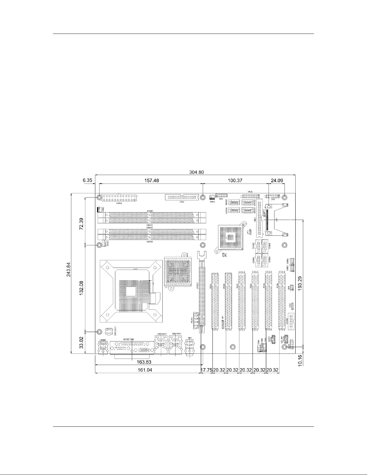
2.2 Dimensions
2.2.1 Board Dimensions
The dimensions of the board are listed below and shown in Figure 2-1.
Length: 305 mm
Width: 244 mm
Figure 2-1: MXGA Dimensions (mm)
CyberResearch, Inc. 9
25 Business Park Drive P: (203) 643-5000; F: (203) 643-5001
Branford, CT USA www.cyberresearch.com
Page 30

MXGA Series CyberResearch® Motherboards
2.2.2 External Interface Panel Dimensions
External peripheral interface connector panel dimensions are shown in Figure 2-2.
Figure 2-2: External Interface Panel Dimensions (mm)
10 ©Copyright 2008 CyberResearch, Inc.
Page 31

CyberResearch® Motherboards MXGA Series
2.3 Data Flow
Figure 2-3 shows the data flow between the two on-board chipsets and other components
installed on the motherboard and described in the following sections of this chapter.
Figure 2-3: Data Flow Block Diagram
CyberResearch, Inc. 11
25 Business Park Drive P: (203) 643-5000; F: (203) 643-5001
Branford, CT USA www.cyberresearch.com
Page 32

MXGA Series CyberResearch® Motherboards
2.4 Compatible Processors
2.4.1 CPU Overview
LGA775 Intel® Core™ 2 Duo, Intel® Pentium® 4, Intel® Pentium® D and Intel® Celeron®
D processors can be installed on the MXGA motherboard. The Intel
processors and the Intel
Technology (Intel
®
®
Celeron® D processors all have Intel® Extended Memory 64
EMT64T)
2.4.2 Supported Intel® Core™ 2 Duo Processors
Specifications for the compatible Intel® Core™ 2 Duo processors are listed in Table 2-1.
CPU Speed Bus Speed Mfg. Tech Cache Package Processor No.
2.66 GHz 1066 MHz 65 nm 4 MB LGA775 E6700
®
Pentium® 4
2.40 GHz 1066 MHz 65 nm 4 MB LGA775 E6600
2.13 GHz 1066 MHz 65 nm 2 MB LGA775 E6400
1.86 GHz 1066 MHz 65 nm 2 MB LGA775 E6300
1.80 GHz 800 MHz 65 nm 2 MB LGA775 E4300
Table 2-1: Supported Intel® Core™ 2 Duo Processors
2.4.3 Supported Intel® Pentium® 4 Processors
Specifications for the compatible Intel® Pentium® 4 processors are listed in Table 2-2.
CPU Speed Bus Speed Mfg. Tech Cache Package Processor No.
3.80 GHz 800 MHz 90 nm 2 MB LGA775 672
3.80 GHz 800 MHz 90 nm 1 MB LGA775 570J
3.80 GHz 800 MHz 90 nm 1 MB LGA775 571
Table 2-2: Supported Intel® Pentium® 4 Processors
12 ©Copyright 2008 CyberResearch, Inc.
Page 33

CyberResearch® Motherboards MXGA Series
CyberResearch, Inc. 13
25 Business Park Drive P: (203) 643-5000; F: (203) 643-5001
Branford, CT USA www.cyberresearch.com
Page 34

MXGA Series CyberResearch® Motherboards
2.4.5 Supported Intel® Pentium® D Processors
Specifications for the compatible Intel® Pentium® D processors are listed in Table 2-3.
CPU Speed Bus Speed Mfg. Tech Cache Package Processor No.
3.60 GHz 800 MHz 65 nm 4 MB LGA775 960
3.40 GHz 800 MHz 65 nm 4 MB LGA775 950
3.40 GHz 800 MHz 65 nm 4 MB LGA775 945
Table 2-3: Supported Intel® Pentium® D Processors
2.4.6 Supported Intel® Celeron® D Processors
Specifications for the compatible Intel® Celeron® D processors are listed in Table 2-4
below:
CPU Speed Bus Speed Mfg. Tech Cache Package Processor No.
3.60 GHz 533 MHz 65 nm 512 KB LGA775 365
3.46 GHz 533 MHz 65 nm 512 KB LGA775 360
3.33 GHz 533 MHz 65 nm 512 KB LGA775 356
Table 2-4: Supported Intel® Celeron® D Processors
2.5 Intel® 945G Northbridge Chipset
2.5.1 Intel® 945G Overview
The Intel® 945G northbridge chipset consists of a graphics and memory controller hub
(GMCH). The GMCH on the Intel
(ICH7) through a high speed Direct Media Interface (DMI) chip-to-chip connection. The
®
945G is interfaced to the Intel® I/O Controller Hub 7
high-speed DMI integrates priority based servicing that allows for concurrent traffic and
true isochronous transfer capabilities. Some of the features of the Intel
below.
14 ©Copyright 2008 CyberResearch, Inc.
®
945G are listed
Page 35

CyberResearch® Motherboards MXGA Series
Support 533/800/1066MHz FSB
Supports four, 1GB, 400/533/667MHz dual channel DDR SDRAM DIMMs
Integrated VGA and SDVO (Serial Digital Video Out put) outputs
Integrated Intel
2.0GB/s concurrent DMI bandwidth maximizes chip set communications
PCI Express x16 Graphics Interface with a raw bit rate on data pins of 2Gb/s
Integrated Intel® High Definition Audio
Integrated Intel® Matrix Storage Technology
Integrated Intel® Active Management Technology
Integrated Intel® Flex Memory Technology
®
Graphics Media Accelerator 950 (Intel® GMA 950)
2.5.2 Intel® 945G Memory Support
The Intel® 945G supports four, 2GB, 400/533/667MHz dual channel DDR SDRAM DIMMs.
Four 240-pin memory sockets on the MXGA enable a maximum of 8GB of memory to be
installed on the system. The memory sockets are shown in Figure 2-4.
Figure 2-4: 240-pin DIMM Sockets
2.5.3 Intel® 945G Serial Digital Video Output (SDVO)
Some of the features of the SDVO ports are listed below.
CyberResearch, Inc. 15
25 Business Park Drive P: (203) 643-5000; F: (203) 643-5001
Branford, CT USA www.cyberresearch.com
Page 36

MXGA Series CyberResearch® Motherboards
Two SDVO ports multiplexed with PCI Express graphics interface
200 MHz dot clock on each 12-bit interface
Can combine two channels to form one larger interface
Flat panels up to 2048x1536 @ 60 Hz or
digital CRT/HDTV at 1920x1080 @ 85Hz
Dual independent display options with digital display
Multiplexed digital display channels (Supported with ADD2 Card).
Supports TMDS transmitters or TV -Out encoders
ADD2/ADD2+ card uses PCI Express graphics x16 connector
2.5.4 Intel® 945G Integrated Graphics Media Accelerator 950
The Intel® 945G has the Intel® GMA 950 integrated into the chipset. Some of the features
of the GMA 950 are listed below.
Intel GMA 950 Grap hics Core
o 400MHz 256-bit graphics core
o Up to 10.6 GB/sec memory bandwidth with DDR2 667 MHz system
memory
o 1.6 GPixels/sec and 1.6 GTexels/sec fill rate
o 192 MB maximum video memory
o 2048x1536 at 75 Hz maximum resolution
o Dynamic Display Modes for flat-panel, wide-screen and Digital TV support
o Operating systems supported: Microsoft Windows* XP, Windows* XP
64-bit, Media Center Edition, Windows 2000; Linux-compatible (Xfree86
source available)
High Performance 3D
o Up to 4 pixels per clock rendering
o Microsoft* DirectX* 9 Hardware Acceleration Features: Pixel Shader 2,
Volumetric Textures, Shadow Maps, Slope Scale Depth Bias, Two-Sided
Stencil
o Microsoft* DirectX* 9 Vertex Shader 3.0 and Transform and Lighting
supported in SW through highly optimized Processor Specific Geometry
Pipeline (PSGP)
o Texture Decompression for DirectX* and OpenGL*
16 ©Copyright 2008 CyberResearch, Inc.
Page 37

CyberResearch® Motherboards MXGA Series
o OpenGL* 1.4 support with ARB extensions
Advanced Display Technology
o Consumer Electronic display (Digital TV) support
o Two Serial Digital Video Out (SDVO) ports for flat-panel monitors and/or
TV-out support via ADD2 cards
o Support for Intel Media Expansion Cards, providing TV out and PVR
capability
o Multiple display types (LVDS, DVI-I, DVI-D, HDTV, TV-out, CRT)
o Dual screen support via ADD2 digital video devices
o HDTV 720p and 1080i display resolution support
o Interlaced Display output support
High Quality Media Support
o High Definition Hardware Motion Compensation to support HD hi-bitrate
MPEG2 media playback
o Up and Down Scaling of Video Content
o HD Content Decode – up to two stream support
o 5x3 Overlay Filtering
2.6 Intel® ICH7 Southbridge Chipset
2.6.1 Intel® ICH7 Overview
The ICH7 southbridge chipset on the MXGA has the features are listed below.
Complies with PCI Express Base Specification, Revision 1.0a
Complies with PCI Local Bus Spe cificati on, Revision 2.3 and su pports 33MHz
PCI operations
Supports ACPI Power Management Logic
Contains:
o Enhanced DMA controller
o Interrupt controller
o Timer functions
Integrated SATA host controller with DMA operations on four ports with dat a
transfer rates up to 3.0 Gb/s
Integrated IDE controller supports Ultra ATA 100/66/33
Supports eight USB 2.0 devices with four UHCI controllers and one EHCI
CyberResearch, Inc. 17
25 Business Park Drive P: (203) 643-5000; F: (203) 643-5001
Branford, CT USA www.cyberresearch.com
Page 38

MXGA Series CyberResearch® Motherboards
controller
Complies with System Management Bus (SMBus) Specification, V ersion 2.0
Supports Audio Codec ’97 (AC’97) Revision 2.3
Supports Intel
Contains Low Pin Count (LPC) interface
Supports Firmware Hub (FWH) interface
Serial Peripheral Interface (SPI) for Serial and Shared Flash
1.05 V Core Voltage
Intel® High Definition Audio Interface
Intel® Active Management T echnology
Intel® Quick Resume Technology Support
®
High Definition Audio
2.6.2 Intel® ICH7 Audio Codec ’97 Controller
The Audio Codec ’97 (AC’97) controller integrated into the ICH7 complies with AC’97
Component Specification, Version 2.3. The AC’97 controller is connected to the onboard
audio connector. The audio connector is connected to an optional 5.1 channel or 7.1
channel audio kit with an embedded AC’97 audio codec. The A C’97 controlle r supports u p
to six PCM audio output channels. Complete surround sound requires six-channel audio
consisting of:
Front left
Front right
Back left
Back right
Center
Subwoofer
2.6.3 Intel® ICH7 IDE Interface
The integrated IDE interface on the ICH7 southbridge supports two IDE hard disks and
ATAPI devices, PIO IDE transfers up to 16MB/s and Ultra ATA transfers of 100MB/s. The
integrated IDE interface is able to support the following IDE HDDs:
Ultra A T A/10 0, with data transfer rates up to 100MB/s
Ultra A T A/66, with data transfer rates up to 66MB/s
18 ©Copyright 2008 CyberResearch, Inc.
Page 39

CyberResearch® Motherboards MXGA Series
Ultra A T A/33, with data transfer rates up to 33MB/s
Table 2-5 shows the supported HDD specifications.
Specification Ultra ATA/100 Ultra ATA/66 Ultra ATA/33
IDE devices 2 2 2
PIO Mode 0 – 4 0 – 4 0 – 4
PIO Max Transfer Rate 16.6 MB/s 16.6 MB/s 16.6 MB/s
DMA/UDMA designation UDMA 3 - 4 UDMA 3 – 4 UDMA 2
DMA/UDMA Max Transfer 100MB/s 66MB/s 33MB/s
Controller Interface 5V 5V 5V
Table 2-5: Supported HDD Specifications
2.6.4 Intel® ICH7 Low Pin Count (LPC) Interface
The ICH7 LPC interface complies with the LPC 1.1 specifications. The LPC bus from the
ICH7 is connected to the following components:
BIOS chipset
Super I/O chipset
2.6.5 Intel® ICH7 PCI Interface
The PCI interface on the ICH7 is compliant with the PCI Revision 2.3 implementation.
Some of the features of the PCI interface are listed below.
PCI Revision 2.3 compliant
33MHz
5V tolerant PCI signals (except PME#)
Integrated PCI arbiter supports up to seven PCI bus masters
Three of the seven PCI bus masters are interfaces to the following onboard components:
PCI slot connector on the bottom of the motherboard
Broadcom PCI Express GbE interface
CyberResearch, Inc. 19
25 Business Park Drive P: (203) 643-5000; F: (203) 643-5001
Branford, CT USA www.cyberresearch.com
Page 40

MXGA Series CyberResearch® Motherboards
ITE PCI-to-ISA bridge interface
The remaining four PCI bus masters are reserved for four PCI expansion boards that can
be installed on the backplane.
2.6.6 Intel® ICH7 Real Time Clock
256 bytes of battery backed RAM is provided by the Motorola MC146818A real time clock
(RTC) integrated into the ICH7. The RTC operates on a 3V battery and 32.768KHz crystal.
The RTC keeps track of the time and stores system data even when the system is turned
off.
2.6.7 Intel® ICH7 SATA Controller
The integrated SATA controller on the ICH7 southbridge supports four SATA drives with
independent DMA operations. SATA controller specifications are listed below.
Supports four SATA drives
Supports 3.0Gb/s data transfer spe eds
Supports Serial ATA Specification, Revision 1.0a and supports several
optional sections of the Serial ATA II: Extensions to Serial ATA 1.0
Specification, Revision 1.0 (AHCI sup port is required for some elements).
2.6.8 Intel® ICH7 USB Controller
Up to eight high-speed, full-speed or low-speed USB devices are supported by the ICH7.
High-speed USB 2.0, with data transfers of up to 480MB/s, is enabled with the ICH7
integrated Enhanced Host Controller Interface (EHCI) compliant host controller. USB
full-speed and low-speed signaling is supported by the four ICH7 integrated Universal
Host Controller Interface (UHCI) controller.
2.7 PCI Bus Components
2.7.1 PCI Bus Overview
20 ©Copyright 2008 CyberResearch, Inc.
Page 41

CyberResearch® Motherboards MXGA Series
The PCI bus controller on the ICH7 southbridge is compliant with PCI Revision 2.3
specifications and has a 33MHz PCI clock. The components listed below are all
connected to the PCI bus:
PCI Express and PCI slots on the motherboard
Broadcom PCI Express GbE interface
2.7.2 Broadcom PCIe GbE interface
The BCM5787M Broadcom PCIe GbE controller is a 10/100/1000BASE-T Ethernet LAN
controller. The BCM5787M combines a triple-speed IEEE 802.3 compliant Media Access
Controller (MAC) with a triple-speed Ethernet transceiver, a PCIe bus interface, and an
on-chip buffer memory. Some of the BCM5787 controller features are listed below:
Integrated 10/100/1000BASE-T transceiver
Automatic MDI crossover function
PCIe v1.0a
10/100/1000BASE-T full/half-duplex MAC
Wake on LAN support meeting the ACPI requirements
Statistics for SNMP MIB II, Ethernet-like MIB, and Ethernet MIB (802.3z,
clause 30)
Serial EEPROM or serial flash support
JT A G sup po rt
2.8 LPC Bus Components
2.8.1 LPC Bus Overview
The LPC bus is connected to components listed below:
BIOS chipset
Super I/O chipset
2.8.2 BIOS Chipset
The BIOS chipset has a licensed copy of AMI BIOS installed on the chipset. Some of the
BIOS features are listed below:
CyberResearch, Inc. 21
25 Business Park Drive P: (203) 643-5000; F: (203) 643-5001
Branford, CT USA www.cyberresearch.com
Page 42

MXGA Series CyberResearch® Motherboards
AMI Flash BIOS
SMIBIOS (DMI) compliant
Console redirection function support
PXE (Pre-boot Execution Environment) support
USB booting support
2.8.3 Super I/O chipset
The iTE IT8712F Super I/O chipset is connected to the ICH6 southbridge through the LPC
bus. The iTE IT8712F is an LPC interface-based Super I/O device that comes with
Environment Controller integration. Some of the features of the iTE IT8712F chipset are
listed below:
LPC Interface
PC98/99/2001, ACPI and LANDesk Compliant
Enhanced Hardware Monitor
Fan Speed Controller
SmartGuardian Controller
Single +5V Power Supply
Two 16C550 UARTs for serial port control
One IEEE 1284 Parallel Port
Floppy Disk Controller
Keyboard Controller
Watchdog T i mer
Serial IRQ Support
Vbat & Vcch Support
Single +5V Power Supply
Some of the Super I/O features are described in more detail below:
2.8.3.1 Super I/O LPC Interface
The LPC interface on the Super I/O complies with the Intel® Low Pin Count Specification
Rev. 1.0. The LPC interface supports both LDRQ# and SERIRQ protocols as well as PCI
PME# interfaces.
22 ©Copyright 2008 CyberResearch, Inc.
Page 43

CyberResearch® Motherboards MXGA Series
2.8.3.2 Super I/O 16C550 UARTs
The onboard Super I/O has two integrated 16C550 UARTs that can support the following:
Two standard serial ports (COM1 and COM2)
IrDa 1.0 and ASKIR protocols
Another two chipsets connected to the LPC bus provided connectivity to another two serial
port connectors (COM3 and COM4).
2.8.3.3 Super I/O Enhanced Hardware Monitor
The Super I/O Enhanced Hardware Monitor monitors three thermal inputs, VBAT
internally, and eight voltage monitor inputs. These hardware parameters are reported in
the BIOS and can be read from the BIOS Hardware Health Configuration menu.
2.8.3.4 Super I/O Fan Speed Controller
The Super I/O fan speed controller enables the system to monitor the speed of the fan.
One of the pins on the fan connector is reserved for fan speed detection and interfaced to
the fan speed controller on the Super I/O. The fan speed is then reported in the BIOS.
2.8.3.5 Super I/O Parallel Port
The Super I/O parallel port (LPT) supports standard mode, enhanced mode and
high-speed mode parallel port devices. The LPT is compliant with the following LPT
modes.
Standard mode
o Bi-directional SPP compliant
Enhanced mode
o EPP v1.7 compliant
o EPP v1.9 compliant
High-speed mode
o ECP, IEEE 1284 compliant
CyberResearch, Inc. 23
25 Business Park Drive P: (203) 643-5000; F: (203) 643-5001
Branford, CT USA www.cyberresearch.com
Page 44

MXGA Series CyberResearch® Motherboards
2.8.3.6 Super I/O Keyboard Controller
The Super I/O keyboard controller can execute the 8042 instruction set. Some of the
keyboard controller features are listed below:
The 8042 instruction is compatible with a PS/2 keyboard and PS/2 mouse
Gate A20 and Keyboard re set output
Supports multiple keyboard power on events
Supports mouse double-click and/or mouse move power on events
2.9 Environmental and Power Specifications
2.9.1 System Monitoring
Three thermal inputs on the MXGA Super I/O Enhanced Hardware Monitor the following
temperatures:
System temperature
Power temperature
CPU temperature
Eight voltage inputs on the MXGA Super I/O Enhanced Hardware Monitor the following
voltages:
Vcore
+2.5V
+3.3V
+5.0V
+12.0V
DDR Vtt
+1.5V
5VSB
The MXGA Super I/O Enhanced Hardware Monitor also monitors the following voltages
internally:
VBAT
24 ©Copyright 2008 CyberResearch, Inc.
Page 45

CyberResearch® Motherboards MXGA Series
The MXGA Super I/O Enhanced Hardware Monitor also monitors the following fan
speeds:
CPU Fan speed
The values for the above environmental parameters are all recorded in the BIOS
Hardware Health Configuration menu.
2.9.2 Operating Temperature and Temperature Control
The maximum and minimum operating temperatures for the MXGA are listed below.
Minimum Operating Temperature: 0ºC (32°F)
Maximum Operating Temperature: 60°C (140°F)
A cooling fan and heat sink must be installed on the CPU. Thermal paste must be
smeared on the lower side of the heat sink before it is mounted on the CPU. Heat sinks
are also mounted on the northbridge and southbridge chipsets to ensure the operating
temperature of these chips remain low.
2.9.3 Power Consumption
Table 2-6 shows the power consumption parameters for the MXGA running with an Intel®
Pentium
®
4, 3.73 GHz, 1066MHz CPU with 1GB of 677MHz DDR2 memory.
Voltage Current
+3.3V 6.07A
+5V 4.25A
+12V 10.17A
Table 2-6: Power Consumption
CyberResearch, Inc. 25
25 Business Park Drive P: (203) 643-5000; F: (203) 643-5001
Branford, CT USA www.cyberresearch.com
Page 46

MXGA Series CyberResearch® Motherboards
Chapter
3
3 Unpacking
26 ©Copyright 2008 CyberResearch, Inc.
Page 47

CyberResearch® Motherboards MXGA Series
3.1 Anti-static Precautions
WARNING:
Failure to take ESD precautions during the installation of the MXGA
may result in permanent damage to the MXGA and severe injury to the
user.
Electrostatic discharge (ESD) can cause serious damage to electronic components,
including the MXGA. Dry climates are especially susceptible to ESD. It is critical that the
following anti-static precautions are strictly adhered to whenever handling the MXGA or
any other electrical component.
Wear an anti-static wristband - Wearing a simple anti-static wristband can
help to prevent ESD from damaging the MXGA.
Self-grounding - Touch a grounded conducting material before handling and
periodically while handling the MXGA.
Use an anti-static pad - When configuring the MXGA, place it on an
antic-static pad to reduce the possibility of ESD damage.
Only handle the edges of the MXGA - When handling the MXGA, hold it by
its edges.
CyberResearch, Inc. 27
25 Business Park Drive P: (203) 643-5000; F: (203) 643-5001
Branford, CT USA www.cyberresearch.com
Page 48

MXGA Series CyberResearch® Motherboards
3.2 Unpacking
3.2.1 Unpacking Precautions
When the MXGA is unpacked, please do the following:
Follow the anti-static precautions outlined in Section 3.1.
Make sure the packing box is facing upwards so the MXGA does not fall out of
the box.
Make sure all the components shown in Section 3.3 are present.
3.3 Unpacking Checklist
NOTE:
If any components listed in the checklist below are missing, do not
proceed with the installation. Contact CyberResearch, Inc. immediately
by phone (203) 643-5000 or email: sales@cyberresearch.com
3.3.1 Package Contents
The MXGA is shipped with the following components:
Quantity Item Image
1
1
MXGA
ATA 66/100 flat cable
28 ©Copyright 2008 CyberResearch, Inc.
Page 49

CyberResearch® Motherboards MXGA Series
Quantity Item Image
Dual RS-232 cable
2
SATA cables
2
SATA power cable
1
I/O Shielding
1
Mini jumper Pack
1
Utility CD
1
Table 3-1: Package List Contents
3.3.2 Optional Components
The following optional components are available from CyberResearch, Inc.
Item and Part Number
FDD cable
RS-232/422/485 cable
Image
CyberResearch, Inc. 29
25 Business Park Drive P: (203) 643-5000; F: (203) 643-5001
Branford, CT USA www.cyberresearch.com
Page 50

MXGA Series CyberResearch® Motherboards
Dual USB cable
Four USB cable
Table 3-2: Optional Components
30 ©Copyright 2008 CyberResearch, Inc.
Page 51

CyberResearch® Motherboards MXGA Series
Intentionally Blank
CyberResearch, Inc. 31
25 Business Park Drive P: (203) 643-5000; F: (203) 643-5001
Branford, CT USA www.cyberresearch.com
Page 52

MXGA Series CyberResearch® Motherboards
Chapter
4
4 Connector Pinouts
32 ©Copyright 2008 CyberResearch, Inc.
Page 53

CyberResearch® Motherboards MXGA Series
4.1 Peripheral Interface Connectors
Section 4.1.1 shows peripheral interface connector locations. Section 4.1.2 lists all the
peripheral interface connectors seen in Section 4.1.1.
4.1.1 MXGA Layout
Figure 4-1 shows the on-board peripheral connectors, rear panel peripheral connectors
and on-board jumpers.
Figure 4-1: Connector and Jumper Locations
4.1.2 Peripheral Interface Connectors
Table 4-1 shows a list of the peripheral interface connectors on the MXGA. Detailed
descriptions of these connectors can be found below.
Connector Type Label
+12V ATX power connector 4-pin header CPU12V1
ATX power connector 24-pin header PWR1
CyberResearch, Inc. 33
25 Business Park Drive P: (203) 643-5000; F: (203) 643-5001
Branford, CT USA www.cyberresearch.com
Page 54

MXGA Series CyberResearch® Motherboards
Connector Type Label
Audio connector 7-pin header CN4
Auxiliary audio connector 4-pin header AUX1
CD-in connector 4-pin header CD_IN1
CompactFlash connector 50-pin CF slot CF1
Digital input/output connector 10-pin header DIO1
Fan connector - CPU 4-pin wafer FAN1
Fan connector - System 3-pin wafer FAN2
Fan connector - System 3-pin wafer FAN3
Floppy disk drive connector 34-pin box header FDC1
Front panel audio connector 10-pin header CN3
IDE Interface connector 40-pin box header IDE1
Infrared connector 5-pin hea der IR1
Multi-panel connector 14-pin header CN2
PCI Express x16 slot 82-pin PCIe x16 slot PCIE2
PCI Express power connector 4-pin wafer PCN1
PCI slot 124-pin PCI slot PCI1
PCI slot 124-pin PCI slot PCI2
PCI slot 124-pin PCI slot PCI3
PCI slot 124-pin PCI slot PCI4
PCI slot 124-pin PCI slot PCI5
PCI slot 124-pin PCI slot PCI6
SATA drive connector 7-pin SATA SATA1
SATA drive connector 7-pin SATA SATA2
SATA drive connector 7-pin SATA SATA3
SATA drive connector 7-pin SATA SATA4
Serial port connector (RS-232) 10-pin box header COM3
Serial port connector (RS-232) 10-pin box header COM4
34 ©Copyright 2008 CyberResearch, Inc.
Page 55

CyberResearch® Motherboards MXGA Series
Connector Type Label
Serial port connector (RS-232) 10-pin box header COM5
Serial port connector (RS-232) 10-pin box header COM6
Serial port connector (RS-232/422/485) 14-pin header COM2
Serial port connector (RS-422/485) 4-pin header CN1
SPDIF connector 5-pin header CN5
TPM connector 20-pin header TPM1
USB connector 8-pin header USB3
USB connector 8-pin header USB4
Table 4-1: Peripheral Interface Connectors
4.1.3 External Peripheral Interface Panel Connectors
Table 4-2 lists the external peripheral interface panel connectors on the MXGA. Detailed
descriptions of these connectors can be found in.
Connector Type Label
Keyboard/Mouse PS/2 KBMS1
Parallel port connector DB-25 (female) 3IN1_DSUB1A
Ethernet/USB connector RJ-45/USB port combo connector LAN/USB1B
Ethernet/USB connector RJ-45/USB port combo connector LAN/USB2B
Audio connector 3 x Audio jacks CN6
VGA connector DB-15 (female) 3IN1_DSUB1C
Serial connector DB-9 (male) 3IN1_DSUB1B
Table 4-2: External Peripheral Interface Panel Connectors
4.2 Internal Peripheral Connectors
Internal peripheral connectors are found on the motherboard and are only accessible
when the motherboard is outside of the chassis. T his sect ion h as c omplete des cript ion s of
all the internal, peripheral connectors on the MXGA.
CyberResearch, Inc. 35
25 Business Park Drive P: (203) 643-5000; F: (203) 643-5001
Branford, CT USA www.cyberresearch.com
Page 56

MXGA Series CyberResearch® Motherboards
4.2.1 ATX Power Supply Connector (4-pins)
CN Label:
CN Type:
CN Location:
CN Pinouts:
CPU12V1
4-pin ATX power connector (1x4)
See Figure 4-2
See Table 4-3
The 4-pin ATX power supply connector is connected to a +12V ATX power supply.
Figure 4-2: ATX Power Supply Connector (4-pins) Location
PIN DESCRIPTION
1 GND
2 GND
3 +12V
4 +12V
Table 4-3: ATX Power Supply Connector (4-pins) Pinouts
36 ©Copyright 2008 CyberResearch, Inc.
Page 57

CyberResearch® Motherboards MXGA Series
4.2.2 ATX Power Supply Connector (24-pins)
CN Label:
CN Type:
CN Location:
CN Pinouts:
PWR1
24-pin ATX power connector (2x12)
See Figure 4-3
See Table 4-4
The 24-pin ATX power supply connector is connected to a ATX power supply.
Figure 4-3: ATX Power Connector Location
PIN DESCRIPTION PIN DESCRIPTION
1 3.3V01 13 3.3V04
2 3.3V02 14 -12V
3 COM01 15 COM
4 +5V01 16 PS-ON
5 COM02 17 COM04
6 +5V02 18 COM05
7 COM03 19 COM06
CyberResearch, Inc. 37
25 Business Park Drive P: (203) 643-5000; F: (203) 643-5001
Branford, CT USA www.cyberresearch.com
Page 58

MXGA Series CyberResearch® Motherboards
PIN DESCRIPTION PIN DESCRIPTION
8 PWR-OK 20 -5V
9 5VSB 21 +5V03
10 +12V01 22 +5V04
11 +12V02 23 +5V05
12 3.3V03 24 COM07
Table 4-4: ATX Power Connector Pinouts
4.2.3 Audio Connector (8-pin)
CN Label: CN4
CN Type:
CN Location:
CN Pinouts:
7-pin header
See Figure 4-4
See Table 4-5
The 8-pin audio connector is connected to external audio devices including speakers and
microphones for the input and output of audio signals to and from the system.
Figure 4-4: Audio Connector Location (8-pin)
38 ©Copyright 2008 CyberResearch, Inc.
Page 59

CyberResearch® Motherboards MXGA Series
PIN DESCRIPTION PIN DESCRIPTION
1 SUROUTL 2 CENOUT
3 GND 4 GND
5 SUROUTL 6 LFEOUT
7 GND
Table 4-5: Audio Connector Pinouts (8-pin)
4.2.4 Auxiliary Audio Connector (4-pin)
CN Label:
CN Type:
CN Location:
CN Pinouts:
AUX1
4-pin header
See Figure 4-5
See Table 4-6
The 4-pin auxiliary audio connector provides a second audio input to the system.
Figure 4-5: Auxiliary Audio Connector Location (4-pin)
CyberResearch, Inc. 39
25 Business Park Drive P: (203) 643-5000; F: (203) 643-5001
Branford, CT USA www.cyberresearch.com
Page 60

MXGA Series CyberResearch® Motherboards
PIN DESCRIPTION
1 CAUXL
2 GND
3 GND
4 CAUXR
Table 4-6: Auxiliary Audio Connector Pinouts (4-pin)
4.2.5 CD-In Connector
CN Label:
CN Type:
CN Location:
CN Pinouts:
CD_IN1
4-pin header
See Figure 4-6
See Table 4-7
The 4-pin CD-in connector connects a CD to the system.
Figure 4-6: CD-In Connector
40 ©Copyright 2008 CyberResearch, Inc.
Page 61

CyberResearch® Motherboards MXGA Series
PIN DESCRIPTION
1 CDL
2 GND
3 GND
4 CDR
Table 4-7: CD-In Connector
4.2.6 Compact Flash Socket
CN Label:
CN Type:
CN Location:
CN Pinouts:
CF1
50-pin header (2x25)
See Figure 4-7
See Table 4-8
A CF Type I or Type II memory card inserts into the CF socket on the motherboard.
CyberResearch, Inc. 41
25 Business Park Drive P: (203) 643-5000; F: (203) 643-5001
Branford, CT USA www.cyberresearch.com
Page 62

MXGA Series CyberResearch® Motherboards
Figure 4-7: CF Card Socket Location
PIN DESCRIPTION PIN DESCRIPTION
1 GROUND 26 VCC-IN CHECK1
2 DATA 3 27 DATA 11
3 DATA 4 28 DATA 12
4 DATA 5 29 DATA 13
5 DATA 6 30 DATA 14
6 DATA 7 31 DATA 15
7 HDC_CS0# 32 HDC_CS1
8 N/C 33 N/C
9 GROUND 34 IOR#
42 ©Copyright 2008 CyberResearch, Inc.
Page 63

CyberResearch® Motherboards MXGA Series
PIN DESCRIPTION PIN DESCRIPTION
10 N/C 35 IOW#
11 N/C 36 VCC_COM
12 N/C 37 IRQ15
13 VCC_COM 38 VCC_COM
14 N/C 39 CSEL
15 N/C 40 N/C
16 N/C 41 HDD_RESET
17 N/C 42 IORDY
18 SA2 43 SDREQ
19 SA1 44 SDACK#
20 SA0 45 HDD_ACTIVE#
21 DATA 0 46 66DET
22 DATA 1 47 DATA 8
23 DATA 2 48 DATA 9
24 N/C 49 DATA 10
25 VCC-IN CHECK2 50 GROUND
Table 4-8: CF Card Socket Pinouts
CyberResearch, Inc. 43
25 Business Park Drive P: (203) 643-5000; F: (203) 643-5001
Branford, CT USA www.cyberresearch.com
Page 64

MXGA Series CyberResearch® Motherboards
4.2.7 Digital Input/Output (DIO) Connector
CN Label:
CN Type:
CN Location:
CN Pinouts:
DIO1
10-pin header (2x5)
See Figure 4-8
See Table 4-9
The digital input/output connector is managed through a Super I/O chip. The DIO
connector pins are user programmable.
Figure 4-8: DIO Connector Locations
PIN DESCRIPTION PIN DESCRIPTION
1 GND 2 PWR (+5V)
3 XOUT0 4 XOUT1
5 XOUT3 6 XOUT4
7 XIN0 8 XIN1
9 XIN2 10 XIN3
Table 4-9: DIO Connector Pinouts
44 ©Copyright 2008 CyberResearch, Inc.
Page 65

CyberResearch® Motherboards MXGA Series
4.2.8 Fan Connectors
CN Label:
FAN1, FAN2, FAN3
FAN1: 4-pin wafer connector
CN Type:
FAN1, FAN2: 3-pin wafer connector
CN Location:
CN Pinouts:
See Figure 4-9
See Table 4-10
The FAN1, FAN2 and FAN3 cooling fan connectors provide a 12V current to the cooling
fans. The connector has a "rotation" pin to get rotation signals from the fan and notify the
system so the system BIOS can recognize the fan speed. Please note that only certain
fans can issue the rotation signals.
FAN1
FAN2, FAN3
Figure 4-9: Fan Connectors Locations
PIN FAN1 FAN2, FAN3
1 GND GND
2 +12V +12V
3 Rotation Signal Rotation Signal
4 Control
Table 4-10: Fan Connectors Pinouts
CyberResearch, Inc. 45
25 Business Park Drive P: (203) 643-5000; F: (203) 643-5001
Branford, CT USA www.cyberresearch.com
Page 66

MXGA Series CyberResearch® Motherboards
4.2.9 Floppy Disk Connector
CN Label:
CN Type:
CN Location:
CN Pinouts:
FDC1
34-pin header (2x17)
See Figure 4-10
See Table 4-11
The floppy disk connector is connected to a floppy disk drive.
Figure 4-10: FDC Connector Location
PIN DESCRIPTION PIN DESCRIPTION
1 GND 2 REDUCE WRITE
3 GND 4 N/C
5 N/C 6 N/C
7 GND 8 INDEX#
9 GND 10 MOTOR ENABLE A#
11 GND 12 DRIVE SELECT B#
46 ©Copyright 2008 CyberResearch, Inc.
Page 67

CyberResearch® Motherboards MXGA Series
PIN DESCRIPTION PIN DESCRIPTION
13 GND 14 DRIVE SELECT A#
15 GND 16 MOTOR ENABLE B#
17 GND 18 DIRECTION#
19 GND 20 STEP#
21 GND 22 WRITE DATA#
23 GND 24 WRITE GATE#
25 GND 26 TRACK 0#
27 GND 28 WRITE PROTECT#
29 GND 30 READ DATA#
31 GND 32 SIDE 1 SELECT#
33 GND 34 DISK CHANGE#
Table 4-11: FDC Connector Pinouts
CyberResearch, Inc. 47
25 Business Park Drive P: (203) 643-5000; F: (203) 643-5001
Branford, CT USA www.cyberresearch.com
Page 68

MXGA Series CyberResearch® Motherboards
4.2.10 Front Panel Audio Connector
CN Label:
CN Type:
CN Location:
CN Pinouts:
CN3
10-pin header (2x6)
See Figure 4-11
See Table 4-12
The front panel audio connector connects to external audio devices via a system’s front
panel audio interfaces.
Figure 4-11: Front Panel Connector Pinout Locations
PIN DESCRIPTION PIN DESCRIPTION
1 MIC IN 2 GND AUDIO
3 MIC BIAS 4 5V
5 LINE OUT (R) 6 LINE OUT (R) Return
7 NC 8 NC
9 LINE OUT (L) 10 LINE OUT (L) Return
Table 4-12: Front Panel Connector Pinouts
48 ©Copyright 2008 CyberResearch, Inc.
Page 69

CyberResearch® Motherboards MXGA Series
4.2.11 IDE Connector (40-pin)
CN Label:
CN Type:
CN Location:
CN Pinouts:
IDE1
40-pin box header (2x20)
See Figure 4-12
See Table 4-13
One 40-pin IDE device connector on the MXGA supports connectivity to two hard disk
drives.
Figure 4-12: IDE Device Connector Locations
PIN DESCRIPTION PIN DESCRIPTION
1 RESET# 2 GROUND
3 DATA 7 4 DATA 8
5 DATA 6 6 DATA 9
7 DATA 5 8 DATA 10
9 DATA 4 10 DATA 11
11 DATA 3 12 DATA 12
13 DATA 2 14 DATA 13
15 DATA 1 16 DATA 14
17 DATA 0 18 DATA 15
CyberResearch, Inc. 49
25 Business Park Drive P: (203) 643-5000; F: (203) 643-5001
Branford, CT USA www.cyberresearch.com
Page 70

MXGA Series CyberResearch® Motherboards
PIN DESCRIPTION PIN DESCRIPTION
19 GROUND 20 N/C
21 IDE DRQ 22 GROUND
23 IOW# 24 GROUND
25 IOR# 26 GROUND
27 IDE CHRDY 28 GROUND
29 IDE DACK 30 GROUND–DEFAULT
31 INTERRUPT 32 N/C
33 SA1 34 N/C
35 SA0 36 SA2
37 HDC CS0# 38 HDC CS1#
39 HDD ACTIVE# 40 GROUND
Table 4-13: IDE Connector Pinouts
4.2.12 Infrared Interface Connector (5-pin)
CN Label:
CN Type:
CN Location:
CN Pinouts:
The infrared interface connector supports both Serial Infrared (SIR) and Amplitude Shift
Key Infrared (ASKIR) interfaces.
IR1
5-pin header (1x5)
See Figure 4-13
See Table 4-14
50 ©Copyright 2008 CyberResearch, Inc.
Page 71

CyberResearch® Motherboards MXGA Series
Figure 4-13: Infrared Connector Pinout Locations
PIN DESCRIPTION
1 VCC
2 NC
3 IR-RX
4 GND
5 IR-TX
Table 4-14: Infrared Connector Pinouts
4.2.13 Multi-panel Connector
CN Label:
CN Type:
CN Location:
CN Pinouts:
CN2
14-pin header (2x7)
See Figure 4-14
See Table 4-15
CyberResearch, Inc. 51
25 Business Park Drive P: (203) 643-5000; F: (203) 643-5001
Branford, CT USA www.cyberresearch.com
Page 72

MXGA Series CyberResearch® Motherboards
The multi-panel connector connects to external switches and indicators to monitor and
controls the motherboard. These indicators and switches include:
Power button
Reset button
Power LED
HDD LED
PC speaker
Figure 4-14: Multi-panel Connector Location
PIN DESCRIPTION PIN DESCRIPTION
1 ACPILED+ 2 SPEAKER+
3 N/C 4 N/C
5 ACPILED- 6 N/C
7 ATX POWER BUTTON 8 SPEAKER9 GND 10 N/C
11 IDE LED+ 12 RESET SW
13 IDE LED - 14 GND
Table 4-15: Multi-panel Connector Pinouts
52 ©Copyright 2008 CyberResearch, Inc.
Page 73

CyberResearch® Motherboards MXGA Series
4.2.14 PCI Express x16 Slot
CN Label:
CN Type:
CN Location:
CN Pinouts:
PCIe x16 expansion devices can be inserted into the PCIe x16 slot.
PCIE2
82-pin PCIe x16 slot
See Figure 4-15
See Table 4-16 (Side A) Table 4-17 (Side B)
CyberResearch, Inc. 53
25 Business Park Drive P: (203) 643-5000; F: (203) 643-5001
Branford, CT USA www.cyberresearch.com
Page 74

MXGA Series CyberResearch® Motherboards
Figure 4-15: PCI Express x16 Slot Connector Location
54 ©Copyright 2008 CyberResearch, Inc.
Page 75

CyberResearch® Motherboards MXGA Series
PIN NAME PIN NAME PIN NAME PIN NAME
A1 Name A22 HSIn(1) A43 HSIp(6) A64 HSIp(11)
A2 PRSNT#1 A23 GND A44 HSIn(6) A65 HSIn(11)
A3 +12v A24 GND A45 GND A66 GND
A4 +12v A25 HSIp(2) A46 GND A67 GND
A5 GND A26 HSIn(2) A47 HSIp(7) A68 HSIp(12)
A6 JTAG2 A27 GND A48 HSIn(7) A69 HSIn(12)
A7 JTAG3 A28 GND A49 GND A70 GND
A8 JTAG4 A29 HSIp(3) A50 RSVD A71 GND
A9 JTAG5 A30 HSIn(3) A51 GND A72 HSIp(13)
A10 +3.3v A31 GND A52 HSIp(8) A73 HSIn(13)
A11 +3.3v A32 RSVD A53 HSIn(8) A74 GND
A12 PWRGD A33 RSVD A54 GND A75 GND
A13 GND A34 GND A55 GND A76 HSIp(14)
A14 REFCLK+ A35 HSIp(4) A56 HSIp(9) A77 HSIn(14)
A15 REFCLK- A36 HSIn(4) A57 HSIn(9) A78 GND
A16 GND A37 GND A58 GND A79 GND
A17 HSIp(0) A38 GND A59 GND A80 HSIp(15)
A18 HSIn(0) A39 HSIp(5) A60 HSIp(10) A81 HSIn(15)
A19 GND A40 HSIn(5) A61 HSIn(10) A82 GND
A20 RSVD A41 GND A62 GND
A21 GND A42 GND A63 GND
Table 4-16: PCIe x16 Side A Pinouts
CyberResearch, Inc. 55
25 Business Park Drive P: (203) 643-5000; F: (203) 643-5001
Branford, CT USA www.cyberresearch.com
Page 76

MXGA Series CyberResearch® Motherboards
PIN NAME PIN NAME PIN NAME PIN NAME
B1 +12v B22 GND B43 GND B64 GND
B2 +12v B23 HSOp(2) B44 GND B65 GND
B3 RSVD B24 HSOn(2) B45 HSOp(7) B66 HSOp(12)
B4 GND B25 GND B46 HSOn(7) B67 HSOn(12)
B5 SMCLK B26 GND B47 GND B68 GND
B6 SMDAT B27 HSOp(3) B48 PRSNT#2 B69 GND
B7 GND B28 HSOn(3) B49 GND B70 HSOp(13)
B8 +3.3v B29 GND B50 HSOp(8) B71 HSOn(13)
B9 JTAG1 B30 RSVD B51 HSOn(8) B72 GND
B10 3.3Vaux B31 PRSNT#2 B52 GND B73 GND
B11 WAKE# B32 GND B53 GND B74 HSOp(14)
B12 RSVD B33 HSOp(4) B54 HSOp(9) B75 HSOn(14)
B13 GND B34 HSOn(4) B55 HSOn(9) B76 GND
B14 HSOp(0) B35 GND B56 GND B77 GND
B15 HSOn(0) B36 GND B57 GND B78 HSOp(15)
B16 GND B37 HSOp(5) B58 HSOp(10) B79 HSOn(15)
B17 PRSNT#2 B38 HSOn(5) B59 HSOn(10) B80 GND
B18 GND B39 GND B60 GND B81 PRSNT#2
B19 HSOp(1) B40 GND B61 GND B82 RSVD#2
B20 HSOn(1) B41 HSOp(6) B62 HSOp(11)
B21 GND B42 HSOn(6) B63 HSOn(11)
Table 4-17: PCIe x16 Side B Pinouts
4.2.15 PCI Express Power Connector (4-pin)
CN Label: PCN1
CN Type:
4-pin wafer (1x4)
CN Location:
CN Pinouts:
See Figure 4-16
See Table 4-18
56 ©Copyright 2008 CyberResearch, Inc.
Page 77

CyberResearch® Motherboards MXGA Series
The PCI Express power connector provides 12V power to PCIe expansion cards.
Figure 4-16: PCI Express Power Connector Pinout Locations
PIN DESCRIPTION
1 VCC
2 GND
3 GND
4 +12V
Table 4-18: PCI Express Power Connector Pinouts
CyberResearch, Inc. 57
25 Business Park Drive P: (203) 643-5000; F: (203) 643-5001
Branford, CT USA www.cyberresearch.com
Page 78

MXGA Series CyberResearch® Motherboards
4.2.16 PCI Slot
CN Label:
CN Type:
CN Location:
CN Pinouts:
The PCI slot enables a PCI expansion module to be connected to the board.
PCI1 to PCI6
PCI Slot
See Figure 4-17
See Table 4-19
58 ©Copyright 2008 CyberResearch, Inc.
Page 79

CyberResearch® Motherboards MXGA Series
Figure 4-17: PCI Slot Location
CyberResearch, Inc. 59
25 Business Park Drive P: (203) 643-5000; F: (203) 643-5001
Branford, CT USA www.cyberresearch.com
Page 80

MXGA Series CyberResearch® Motherboards
PIN DESCRIPTION PIN DESCRIPTION
A1 TRST B1 -12V
A2 +12V B2 TCK
A3 TMS B3 GND
A4 TDI B4 TDO
A5 +5V B5 +5V
A6 INTA B6 +5V
A7 INTC B7 INTB
A8 +5V B8 INTD
A9 RESERVED3 B9 PRSNT1
A10 +5V B10 RESERVED1
A11 RESERVED4 B11 PRSNT2
A12 GND B12 GND
A13 GND B13 GND
A14 3.3V_AUX B14 RESERVED2
A15 RST B15 GND
A16 +5V B16 CLK
A17 GNT B17 GND
A18 GND B18 REQ
A19 PME B19 +5V
A20 AD30 B20 AD31
A21 +3.3V B21 AD29
A22 AD28 B22 GND
A23 AD26 B23 AD27
A24 GND B24 AD25
A25 AD24 B25 +3.3V
A26 IDSEL B26 C/BE3
A27 +3.3V B27 AD23
A28 AD22 B28 GND
A29 AD20 B29 AD21
A30 GND B30 AD19
A31 AD18 B31 +3.3V
A32 AD16 B32 AD17
60 ©Copyright 2008 CyberResearch, Inc.
Page 81

CyberResearch® Motherboards MXGA Series
PIN DESCRIPTION PIN DESCRIPTION
A33 +3.3V B33 C/BE2
A34 FRAME B34 GND
A35 GND B35 IRDY
A36 TRDY B36 +3.3V
A37 GND B37 DEVSEL
A38 STOP B38 GND
A39 +3.3V B39 LOCK
A40 SDONE B40 PERR
A41 SBO B41 +3.3V
A42 GND B42 SERR
A43 PAR B43 +3.3V
A44 AD15 B44 C/BE1
A45 +3.3V B45 AD14
A46 AD13 B46 GND
A47 AD11 B47 AD12
A48 GND B48 AD10
A49 AD9 B49 GND
A52 C/BE0 B52 AD8
A53 +3.3V B53 AD7
A54 AD6 B54 +3.3V
A55 AD4 B55 AD5
A56 GND B56 AD3
A57 AD2 B57 GND
A68 AD0 B68 AD1
A59 +5V B59 +5V
A60 REQ64 B60 ACK64
A61 +5V B61 +5V
A62 +5V B62 +5V
Table 4-19: PCI Slot
CyberResearch, Inc. 61
25 Business Park Drive P: (203) 643-5000; F: (203) 643-5001
Branford, CT USA www.cyberresearch.com
Page 82

MXGA Series CyberResearch® Motherboards
4.2.17 SATA Drive Connectors
CN Label:
CN Type:
CN Location:
CN Pinouts:
The SATA drive connectors are connected to SATA 3Gb/s disk drives that transfer data at
speeds as high as 3.0Gb/s.
SATA1, SATA2, SATA3 and SATA4
7-pin SATA drive connectors
See Figure 4-18
See Table 4-20
Figure 4-18: SATA Drive Connector Locations
62 ©Copyright 2008 CyberResearch, Inc.
Page 83

CyberResearch® Motherboards MXGA Series
PIN DESCRIPTION
1 GND
2 TX+
3 TX-
4 GND
5 RX-
6 RX+
7 GND
Table 4-20: SATA Drive Connector Pinouts
4.2.18 Serial Port Connector (RS-232)
CN Label:
CN Type:
CN Location:
CN Pinouts:
COM3 to COM6
10-pin box header (2x5)
See Figure 4-19
See Table 4-21
The 10-pin serial port connectors provide RS-232 serial communications channels that
can be connected to external RS-232 serial port devices.
CyberResearch, Inc. 63
25 Business Park Drive P: (203) 643-5000; F: (203) 643-5001
Branford, CT USA www.cyberresearch.com
Page 84

MXGA Series CyberResearch® Motherboards
COM3, COM4, COM5, COM6
Figure 4-19: Serial Port Connector (RS-232) Pinout Locations
PIN DESCRIPTION PIN DESCRIPTION
1 DCD- 6 DSR-
2 SIN 7 RTS3 SOUT 8 CTS-
4 DTR- 9 RI
5 GND 10 GND
Table 4-21: Serial Port Connector (RS-232) Pinouts
4.2.19 Serial Port Connector (RS-232/422/485)
CN Label:
CN Type:
CN Location:
CN Pinouts:
The 14-pin serial port connector provides an RS-232/422/485 serial communications
channel that can be connected to external RS-232/422/485 serial port devices. The signal
type is controlled via the JP4 jumper and is shared with the CN1 connector.
COM2
14-pin header (2x7)
See Figure 4-20
See Table 4-22
64 ©Copyright 2008 CyberResearch, Inc.
Page 85

CyberResearch® Motherboards MXGA Series
Figure 4-20: Serial Port Connector (RS-232/422/485) Pinout Locations
PIN DESCRIPTION PIN DESCRIPTION
1 DCD 2 DSR
3 RXD 4 RTS
5 TXD 6 CTX
7 DTR 8 RI
9 GND 10 NC
11 TXD1+ 12 TXD1-
13 RXD1+ 14 RXD1-
Table 4-22: Serial Port Connector (RS-232/422/485) Pinouts
CyberResearch, Inc. 65
25 Business Park Drive P: (203) 643-5000; F: (203) 643-5001
Branford, CT USA www.cyberresearch.com
Page 86

MXGA Series CyberResearch® Motherboards
4.2.20 Serial Port Connector (RS-422/485)
CN Label:
CN Type:
CN Location:
CN Pinouts:
CN1
4-pin header
See Figure 4-21
See Table 4-23
The 4-pin serial port connector provides RS-422/485 serial communications channels that
can be connected to external RS-422/485 serial port devices. The port is shared with the
COM2 port.
Figure 4-21: Serial Port Connector (RS-422/485) Pinout
Locations
PIN DESCRIPTION
1 TXD1+
2 TXD13 RXD1+
4 RXD1-
Table 4-23: Serial Port Connector (RS-422/485) Pinouts
66 ©Copyright 2008 CyberResearch, Inc.
Page 87

CyberResearch® Motherboards MXGA Series
4.2.21 SPDIF Connector
CN Label:
CN Type:
CN Location:
CN Pinouts:
CN5
5-pin header
See Figure 4-22
See Table 4-24
Use the SPDIF connector to connect digital audio devices to the system.
Figure 4-22: SPDIF Connector Pinout Locations
PIN DESCRIPTION
1 VCC AUDIO
2 NC
3 SPDIF OUT
4 GND AUDIO
5 SPDIF IN
Table 4-24: SPDIF Connector Pinouts
CyberResearch, Inc. 67
25 Business Park Drive P: (203) 643-5000; F: (203) 643-5001
Branford, CT USA www.cyberresearch.com
Page 88

MXGA Series CyberResearch® Motherboards
4.2.22 TPM Connector
CN Label:
CN Type:
CN Location:
CN Pinouts:
Use the TPM connector to connect a TPM module to the system.
TPM1
20-pin header (2x10)
See Figure 4-23
See Table 4-25
Figure 4-23: TPM Connector Pinout Locations
68 ©Copyright 2008 CyberResearch, Inc.
Page 89

CyberResearch® Motherboards MXGA Series
PIN DESCRIPTION PIN DESCRIPTION
1 LCLK 2 GND
3 LFRAME# 4 KEY
5 LRESET# 6 +5V
7 LAD3 8 LAD2
9 +3V 10 LAD1
11 LAD0 12 GND
13 SCL 14 SDA
15 SB3V 16 SERIRQ
17 GND 18 GLKRUN#
19 LPCPD# 20 LDRQ#
Table 4-25: TPM Connector Pinouts
CyberResearch, Inc. 69
25 Business Park Drive P: (203) 643-5000; F: (203) 643-5001
Branford, CT USA www.cyberresearch.com
Page 90

MXGA Series CyberResearch® Motherboards
4.2.23 USB Connectors (Internal)
CN Label:
CN Type:
CN Location:
CN Pinouts:
USB3, USB4
8-pin header (2x4)
See Figure 4-24
See Table 4-26
The 2x4 USB pin connectors each provide connectivity to two USB 1.1 or two USB 2.0
ports. Each USB connector can support two USB devices. Additional external USB ports
are found on the rear panel. The USB ports are used for I/O bus expansion.
Figure 4-24: USB Connector Pinout Locations
PIN DESCRIPTION PIN DESCRIPTION
1 PWR (+5V) 2 GND
3 USBPB- 4 USBPB+
5 USBPA+ 6 USBPB-
7 GND 8 PWR (+5V)
Table 4-26: USB Port Connector Pinouts
70 ©Copyright 2008 CyberResearch, Inc.
Page 91

CyberResearch® Motherboards MXGA Series
4.3 External Peripheral Interface Connectors
The external peripheral interface connectors on the back panel are connected to devices
externally when the MXGA is installed in a chassis. The peripheral connectors on the rear
panel are:
1 x Keyboard/mouse connector
1 x Parallel port connector
2 x RJ-45 Ethernet connector
3 x Audio jacks
4 x USB 2.0 connectors
1 x VGA connector
1 x Serial port connector
Figure 4-25: MXGA External Interface Connectors
CyberResearch, Inc. 71
25 Business Park Drive P: (203) 643-5000; F: (203) 643-5001
Branford, CT USA www.cyberresearch.com
Page 92

MXGA Series CyberResearch® Motherboards
4.3.1 Keyboard/Mouse Connector
CN Label: KBMS1
CN Type: PS/2 connector
CN Location: See Figure 4-25 (labeled number 1)
CN Pinouts: See Figure 4-26 and Table 4-27
The MXGA keyboard and mouse connectors are standard PS/2 connectors.
Figure 4-26: PS/2 Pinouts
PIN DESCRIPTION PIN DESCRIPTION
1 L_KDAT 7 L_MDAT
2 NC 8 NC
3 GND 9 GND
4 5V 10 5V
5 L_KCLK 11 L_MCLK
6 NC 12 NC
Table 4-27: PS/2 Connector Pinouts
72 ©Copyright 2008 CyberResearch, Inc.
Page 93

CyberResearch® Motherboards MXGA Series
4.3.2 Parallel Port Connector
CN Label: 3IN1_DSUB1A
CN Type: DB-25
CN Location: See Figure 4-25 (labeled number 2)
CN Pinouts: See Figure 4-27 and Table 4-28
These ports are usually connected to a printer. MXGA includes one on-board parallel
ports accessed through one 25-pin D-type female connector.
Figure 4-27: Parallel Port Connector Pinout Locations
PIN Description PIN Description
1 STROBE# 2 DATA 0
3 DATA 1 4 DATA 2
5 DATA 3 6 DATA 4
7 DATA 5 8 DATA 6
9 DATA 7 10 ACKNOWLEDGE
11 BUSY 12 PAPER EMPTY
13 PRINTER SELECT 14 AUTO FORM FEED #
15 ERROR# 16 INITIALIZE
17 PRINTER SELECT LN# 18 GND
19 GND 20 GND
21 GND 22 GND
23 GND 24 GND
25 GND
Table 4-28: Parallel Port Connector Pinouts
CyberResearch, Inc. 73
25 Business Park Drive P: (203) 643-5000; F: (203) 643-5001
Branford, CT USA www.cyberresearch.com
Page 94

MXGA Series CyberResearch® Motherboards
4.3.3 Ethernet Connector
CN Label: LAN/USB1B, LAN/USB2B
CN Typ e: RJ-45 ports
CN Location: See Figure 4-25 (labeled 3)
CN Pinouts:
See Figure 4-28, Table 4-29 and Table 4-30
A 1Gb connection can be made between the Ethernet connectors and a Local Area
Network (LAN) through a network hub.
Figure 4-28: Ethernet Connector Pinout Locations
PIN DESCRIPTION PIN DESCRIPTION
1 TX+ (or MDX0+) 5 N/C (or MDX2-)
2 TX- (or MDX0-) 6 RX- (or MDX1-)
3 RX+ (or MDX1+) 7 N/C (or MDX3+)
4 N/C (or MDX2+) 8 N/C (or MDX3-)
13 MDX0+ 17 MDX214 MDX0- 18 MDX1-
15 MDX1+ 19 MDX3+
16 MDX2+ 20 MDX3-
1 TX+ (or MDX0+) 5 N/C (or MDX2-)
2 TX- (or MDX0-) 6 RX- (or MDX1-)
Table 4-29: Ethernet Connector Pinouts
74 ©Copyright 2008 CyberResearch, Inc.
Page 95

CyberResearch® Motherboards MXGA Series
Figure 4-29: Ethernet Connector
The RJ-45 Ethernet connector has two status LEDs, one green and one yello w. The green
LED indicates activity on the port and the yellow LED indicates the port is linked
(Table 4-30).
SPEED LED LINK LED
Status Description Status Description
GREEN ON: 100MB
OFF: 10MB
YELLOW ON: Linked
Flashing: Activity
Table 4-30: Ethernet Connector LEDs
4.3.4 Audio Connectors
CN Label: CN6
CN Type: Audio jack
CN Location: See Figure 4-25 (labeled number 4)
CN Pinouts: See Figure 4-30
Line In port (Light Blue): Connects a CD-ROM, DVD player, or other audio
devices.
Speaker Out port (Lime): Connects to a headphone or a speaker. With
multi-channel configurations, this port can also connect to front speakers.
Microphone (Pink): Connects a microphone.
CyberResearch, Inc. 75
25 Business Park Drive P: (203) 643-5000; F: (203) 643-5001
Branford, CT USA www.cyberresearch.com
Page 96

MXGA Series CyberResearch® Motherboards
Figure 4-30: Audio Connector
4.3.5 USB Connectors
CN Label: LAN/USB1B, LAN/USB2B
CN Type: Dual USB port
CN Location: See Figure 4-25 (labeled 5)
CN Pinouts: See Figure 4-31 and Table 4-31
USB devices connect directly to the USB connectors on the external peripheral connector
panel.
Figure 4-31: USB Connector Pinout Locations
PIN DESCRIPTION PIN DESCRIPTION
1 VCC 5 VCC
2 USBD0- 6 USBD03 USBD0+ 7 USBD0+
4 GND 8 GND
Table 4-31: USB Connector Pinouts
76 ©Copyright 2008 CyberResearch, Inc.
Page 97

CyberResearch® Motherboards MXGA Series
4.3.6 VGA Connector
CN Label: 3IN1_DSUB1C
CN Type: HD-D-sub 15 Female connector
CN Location: See Figure 4-25 (labeled 6)
CN Pinouts:
See Figure 4-32 and Table 4-32
The standard HD-D-sub 15 female connector connects to a CRT or LCD monitor.
Figure 4-32: VGA Connector
PIN Description PIN Description
1 RED 2 GREEN
3 BLUE 4 N/C
5 GND 6 GND
7 GND 8 GND
9 VCC 10 GND
11 N/C 12 DDC DAT
13 HSYNC 14 VSYNC
15 DDC CLK
Table 4-32: VGA Connector Pinouts
CyberResearch, Inc. 77
25 Business Park Drive P: (203) 643-5000; F: (203) 643-5001
Branford, CT USA www.cyberresearch.com
Page 98

MXGA Series CyberResearch® Motherboards
4.3.7 Serial Communications Connector
CN Label: 3IN1_DSUB1B
CN Type: D-sub 9 Male connector
CN Location: See Figure 4-25 (labeled 7)
CN Pinouts:
See Figure 4-33 and Table 4-33
The serial connector on the external interface panel provides serial connection in the
RS-232 mode.
Figure 4-33: Serial Communications Connector Pinout Locations
PIN DESCRIPTION
1 DATA CARRIER DETECT (DCD)
2 RECEIVE DATA (RXD)
3 TRANSMIT DATA (TXD)
4 DATA TERMINAL READY (DTR)
5 GROUND (GND)
6 DATA SET READY (DSR)
7 REQUEST TO SEND (RTS)
8 CLEAR TO SEND (CTS)
9 RING INDICATOR (RI)
Table 4-33: COM1 RS-232 Mode Connector Pinouts
4.4 On-board Jumpers
The MXGA has fifteen on-board jumpers. Refer to Section 5.4 for jumper configuration
settings.
78 ©Copyright 2008 CyberResearch, Inc.
Page 99

CyberResearch® Motherboards MXGA Series
Intentionally Blank
CyberResearch, Inc. 79
25 Business Park Drive P: (203) 643-5000; F: (203) 643-5001
Branford, CT USA www.cyberresearch.com
Page 100

MXGA Series CyberResearch® Motherboards
Chapter
5
5 Installation
80 ©Copyright 2008 CyberResearch, Inc.
 Loading...