

Page 1

Industrial Monitors
MPD Series
NEMA 4 Sealed Industrial
Monitors with Optional
Touchscreen
®
USER’S MANUAL
VER. 2.0C • MAY 2008
No part of this manual may be reproduced without permission
CyberResearch®,Inc.
www.cyberresearch.com
25 Business Park Dr., Branford, CT 06405 USA
203-483-8815 (9am to 5pm EST) FAX: 203-483-9024
Page 2

Page 3

CyberResearch® Industrial Monitors MPD Series
©Copyright 2008
All Rights Reserved.
May 10th 2008
The information in this document is subject to change without prior notice
in order to improve reliability, design, and function and does not represent
a commitment on the part of CyberResearch, Inc.
In no event will CyberResearch, Inc. be liable for direct, indirect, special,
incidental, or consequential damages arising out of the use of or inability
to use the product or documentation, even if advised of the possibility of
such damages.
This document contains proprietary information protected by copyright.
All rights are reserved. No part of this manual may be reproduced by any
mechanical, electronic, or other means in any form without prior written
permission of CyberResearch, Inc.
Trademarks
“CyberResearch,” and “MPD Series,” are trademarks of CyberResearch,
Inc. Other product names mentioned herein are used for identification
purposes only and may be trademarks and/or registered trademarks of
their respective companies.
• NOTICE •
CyberResearch, Inc. does not authorize any CyberResearch product for
use in life support systems, medical equipment, and/or medical devices
without the written approval of the President of CyberResearch, Inc. Life
support devices and systems are devices or systems which are intended
for surgical implantation into the body, or to support or sustain life and
whose failure to perform can be reasonably expected to result in injury.
Other medical equipment includes devices used for monitoring, data
acquisition, modification, or notification purposes in relation to life
support, life sustaining, or vital statistic recording. CyberResearch
products are not designed with the components required, are not subject
to the testing required, and are not submitted to the certification required
to ensure a level of reliability appropriate for the treatment and diagnosis of
humans.
CyberResearch, Inc. iii
25 Business Park Drive P: (203) 643-5000; F: (203) 643-5001
Branford, CT USA www.cyberresearch.com
Page 4

MPD Series CyberResearch® Industrial Monitors
MPD Series
Revision # Description Date of Issue
1.1 Initial Release July 2007
2.0C Revision May 10th 2008
iv ©Copyright 2008 CyberResearch, Inc.
Page 5

CyberResearch® Industrial Monitors MPD Series
CyberResearch, Inc. v
25 Business Park Drive P: (203) 643-5000; F: (203) 643-5001
Branford, CT USA www.cyberresearch.com
Page 6

MPD Series CyberResearch® Industrial Monitors
ABOUT THIS MANUAL
This document covers the description and installation instructions for the MPD Series
Industrial Monitors. The monitors in this series include the MPD 19AG, MPD 17AG, MPD
15AG, MPD 12AG, MPD 10AG, MPD 08AG and MPD 06AG. Model variations will reflect
the different implementation options, e.g., touch panel.
SAFETY PRECAUTIONS
Prior to installing, moving, and modifying the monitor, make sure the power is
turned off and the power cord is disconnected.
Do not apply voltage levels that exceed the specified voltage range. Doing so will
cause fire or an electrical shock.
Electric shocks can occur if the panel is opened. Do not drop or insert any objects
into the ventilation openings of the monitor.
Designs with stand-alone and fault-tolerant hardware considerations should be
implemented using the series models as a critical alarm or production line control.
If considerable amount of dust, water, or fluids entered the monitor, turn off the
power supply immediately, unplug the power cord, and contact the monitor
vendor.
Explosions may occur with installations in environments where flammable gases
are present.
Fault-tolerant and failsafe designs should be implemented with the use of the
series models on transportation vehicles, ships, safety/security devices, or
medical devices not related to life-support functionalities. Users should take the
responsibility for implementations with adequate levels of reliability and safety.
FURTHER PRECAUTIONS
Do not drop the monitor against a hard surface. Doing so will damage the display.
Do not strike or exert excessive force onto the touch panel.
Touching the touch panel using a sharp object will damage the LCD panel.
Avoid environments exposed to direct sunlight, dust, or chemical vapors.
vi ©Copyright 2008 CyberResearch, Inc.
Page 7

CyberResearch® Industrial Monitors MPD Series
The ambient temperature of the installation site should be observed and
controlled to avoid overheating the monitor.
Condensation might form inside the monitor chassis if exposed to sudden
changes in temperature.
Carefully route the power cord so that people cannot step on it. Do not place
anything over the power cord.
If the equipment should be left unused for an extended period of time, disconnect
it from the power source to avoid damage by transient over-voltage.
If any of the following situations arise, have the equipment checked by qualified
service personnel:
o The power cord or plug is damaged.
o Liquid has penetrated into the equipment.
o The equipment has been exposed to moisture.
o The equipment does not work properly, or cannot be made to work
according to the user manual.
o The equipment has been dropped and damaged.
o The equipment shows obvious signs of damage.
WARNING!
Any changes or modifications made to the equipment that are not
expressly approved by the relevant standards could void the authority to
operate the equipment.
ADDITIONAL INFORMA TION AND ASSISTANCE
MAINTENANCE AND CLEANING
Prior to cleaning any part or component of the monitor, please read the details below.
Except for the properly installed front LCD panel, never spray or squirt liquids
directly onto any other component. To clean the front panel, please rub it with a
piece of soft dry cloth or a slightly moistened cloth.
The interior of the LCD monitor does not require cleaning. Keep fluids away from
the LCD monitor interior.
CyberResearch, Inc. vii
25 Business Park Drive P: (203) 643-5000; F: (203) 643-5001
Branford, CT USA www.cyberresearch.com
Page 8

MPD Series CyberResearch® Industrial Monitors
Be cautious of all small removable components when vacuuming the monitor.
Turn the system off before cleaning the LCD monitor.
Never drop any objects or liquids through the openings of the LCD monitor.
Be cautious of any possible allergic reactions to solvents or chemicals used when
cleaning the monitor.
Avoid eating, drinking and smoking within vicinity of the monitor.
CLEANING TOOLS
Some components in the monitor may only be cleaned using a product specifically
designed for the purpose. In such case, the product will be explicitly mentioned in the
cleaning tips. Below is a list of items to use when cleaning the computer or computer
peripherals.
Cloth – Although paper towels or tissues can be used, a soft, clean piece of cloth
is recommended when cleaning the monitor.
Water or rubbing alcohol – A cloth moistened with water or rubbing alcohol can
be used to clean the monitor.
Using solvents – The use of solvents is not recommended when cleaning the
monitor as they may damage the plastic parts.
Vacuum cleaner – Using a vacuum specifically designed for computers is one of
the best methods of cleaning the monitor. Over dust and dirt can restrict the
airflow in a computer and cause circuitry to corrode.
Cotton swabs - Cotton swaps moistened with rubbing alcohol or water are
excellent tools for wiping hard to reach areas.
Foam swabs - Whenever possible, it is best to use lint free swabs such as foam
swabs for cleaning.
ESD PRECAUTIONS
Observe all conventional anti-ESD methods while handling the components contained
within the LCD should the need arise for adding a functionality. The use of a grounded
wrist strap and an anti-static work pad is recommended. Avoid dust and debris or other
static-accumulating materials in the work area.
viii ©Copyright 2008 CyberResearch, Inc.
Page 9

CyberResearch® Industrial Monitors MPD Series
CyberResearch, Inc. ix
25 Business Park Drive P: (203) 643-5000; F: (203) 643-5001
Branford, CT USA www.cyberresearch.com
Page 10
MPD Series CyberResearch® Industrial Monitors
CONVENTIONS USED IN THIS MANUAL
WARNING!
Warnings appear where overlooked details may cause damage to the equipment or result
in personal injury. Warnings should be taken seriously. Warnings are easy to recognize.
The word “warning” is written as “WARNING,” both capitalized and bold and is followed by
text in italics. The italicized text is the warning message.
CAUTION!
Cautionary messages should also be heeded to helps reduce the chance of losing data or
damaging the system. Cautions are easy to recognize. The word “caution” is written as
“CAUTION,” both capitalized and bold and is followed by text in italics. The italicized text is
the cautionary message.
NOTE:
These messages inform the reader of essential but non-critical information. These
messages should be read carefully as any directions or instructions contained therein can
helps avoid making mistakes. Notes are easy to recognize. The word “note” is written as
“NOTE,” both capitalized and bold and is followed by text in italics. The italicized text is the
cautionary message.
LISTS
Bulleted Lists: Bulleted lists are statements of non-sequential facts that can be read in
any order. Each statement is preceded by a round black dot “•” or bullets in other shapes.
Numbered Lists: Numbered lists describe sequential steps should be followed in order.
x ©Copyright 2008 CyberResearch, Inc.
Page 11

CyberResearch® Industrial Monitors MPD Series
Table of Contents
1 INTRODUCTION..................................................................................................... 1
1.1 MPD SERIES INDUSTRIAL MONITOR OVERVIEW ........................................................ 2
1.1.1 Standard Features.............................................................................................. 2
1.1.2 Model Variations................................................................................................ 2
1.2 APPLICATIONS AND FEATURES.................................................................................... 2
1.2.1 MPD Series Industrial Monitor Applications.................................................... 2
1.2.2 MPD Series Industrial Monitor Features.......................................................... 3
1.3 EXTERNAL OVERVIEW................................................................................................ 4
1.3.1 Front View.......................................................................................................... 5
1.3.2 Bottom Panel View............................................................................................. 6
1.3.3 LCD Controller.................................................................................................. 7
1.4 SERIES SPECIFICATIONS.............................................................................................. 8
1.5 CERTIFICATIONS......................................................................................................... 9
2 MECHANICAL OVERVIEW................................................................................11
2.1 INTRODUCTION......................................................................................................... 12
2.2 FRONT PANEL........................................................................................................... 12
2.2.1 Front Panel Variants........................................................................................ 12
2.2.2 Front Panel Variant 1....................................................................................... 13
2.2.3 Front Panel Variant 2....................................................................................... 14
2.2.4 Front Panel Variant 3....................................................................................... 15
2.3 BOTTOM PANEL........................................................................................................ 15
2.3.1 A vailable Connectors....................................................................................... 15
2.3.2 MPD 06AG Connectors................................................................................... 16
2.3.3 MPD 08AG Connectors................................................................................... 16
2.3.4 MPD 10AG Connectors................................................................................... 16
2.3.5 MPD 12AG Connectors................................................................................... 17
2.3.6 MPD 15AG Connectors................................................................................... 17
2.3.7 MPD 17AG Connectors................................................................................... 17
2.3.8 MPD 19AG Connectors................................................................................... 18
2.4 PHYSICAL DIMENSIONS............................................................................................ 18
CyberResearch, Inc. xi
25 Business Park Drive P: (203) 643-5000; F: (203) 643-5001
Branford, CT USA www.cyberresearch.com
Page 12

MPD Series CyberResearch® Industrial Monitors
2.4.1 General Physical Dimensions.......................................................................... 18
2.4.2 MPD 19AG Physical Dimensions.................................................................... 19
2.4.3 MPD 17AG Physical Dimensions.................................................................... 20
2.4.4 MPD 15AG Physical Dimensions.................................................................... 21
2.4.5 MPD 12AG Physical Dimensions.................................................................... 22
2.4.6 MPD 10AG Physical Dimensions.................................................................... 23
2.4.7 MPD 08AG Physical Dimensions.................................................................... 24
2.4.8 MPD 06AG Physical Dimensions.................................................................... 25
2.5 OPTIONAL MOUNTING KITS ..................................................................................... 26
2.5.1 MPD 06AG Mounting Kits............................................................................... 26
2.5.2 MPD 08AG Mounting Kits............................................................................... 26
2.5.3 MPD 10AG Mounting Kits............................................................................... 27
2.5.4 MPD 12AG Mounting Kits............................................................................... 27
2.5.5 MPD 15AG Mounting Kits............................................................................... 28
2.5.6 MPD 17AG Mounting Kits............................................................................... 28
2.5.7 MPD 19AG Mounting Kits............................................................................... 29
2.6 MOUNTING OPTIONS................................................................................................ 29
2.6.1 Panel Mounting................................................................................................ 29
2.6.2 Rack and Cabinet Mounting ............................................................................ 31
2.6.3 Wall Mounting.................................................................................................. 32
2.6.4 DIN Rail Mounting .......................................................................................... 33
2.6.5 Monitor Arm or Stand Mounting......................................................................34
3 LCD AND TOUCH PANEL SPECIFICATIONS ................................................ 35
LCD SPECIFICATIONS............................................................................................... 36
3.1
3.1.1 LCD Overview ................................................................................................. 36
3.1.2 MPD 19AG LCD Specifications ...................................................................... 37
3.1.3 MPD 17AG LCD Specifications ...................................................................... 38
3.1.4 MPD 15AG LCD Specifications ...................................................................... 39
3.1.5 MPD 12AG LCD Specifications ...................................................................... 40
3.1.6 MPD 10AG LCD Specifications ...................................................................... 41
3.1.7 MPD 08AG LCD Specifications ...................................................................... 42
3.1.8 MPD 06AG LCD Specifications ...................................................................... 43
3.2 OPTIONAL TOUCH PANELS ....................................................................................... 44
3.2.1 Touch Panel Models......................................................................................... 44
xii ©Copyright 2008 CyberResearch, Inc.
Page 13

CyberResearch® Industrial Monitors MPD Series
3.2.2 Touch Panel Dimensions.................................................................................. 45
3.2.3 Touch Panel Specifications .............................................................................. 46
3.2.4 Touch Panel RS-232 Controller Specifications................................................ 47
3.2.5 Touch Panel USB Controller Specifications.................................................... 48
3.3 POWER ADAPTERS.................................................................................................... 49
4 LCD CONTROLLERS .......................................................................................... 51
4.1 LCD CONTROLLER OVERVIEW ................................................................................ 52
4.2 9350 LCD CONTROLLER.......................................................................................... 52
4.2.1 9350 LCD Controller Overview....................................................................... 52
4.2.2 9350 LCD Controller Connectors.................................................................... 52
4.2.3 9350 LCD Controller Layout........................................................................... 53
4.2.4 9350 LCD Controller Peripheral Interface Connectors.................................. 54
4.2.5 9350 LCD Controller Rear Panel Connectors ................................................ 54
4.2.6 9350 LCD Controller Onboard Jumper........................................................... 55
4.2.7 9350 LCD Controller Internal Peripheral Connectors ................................... 55
4.2.8 5V Power Connector........................................................................................ 56
4.2.9 Debugged Port Connector............................................................................... 57
4.2.10 External OSD and LED Indication Connector.............................................. 59
4.2.11 Serial Communications Connector ................................................................ 60
4.2.12 TTL Output Connector................................................................................... 61
4.2.13 VGA Connector.............................................................................................. 63
4.2.14 9350 External (Rear Panel) Connectors........................................................ 64
4.2.15 DC 12V Connector......................................................................................... 64
4.2.16 RS232 Serial Connector................................................................................. 65
4.2.17 OSD Control Buttons..................................................................................... 66
4.2.18 VGA Connector.............................................................................................. 67
4.2.19 9350 Onboard Jumper................................................................................... 68
4.2.20 LCD Panel (TTL) Voltage Select Jumper....................................................... 69
5350 LCD CONTROLLER.......................................................................................... 70
4.3
4.3.1 5350 LCD Controller Overview....................................................................... 70
4.3.2 5350 LCD Controller Connectors.................................................................... 70
4.3.3 5350 LCD Controller Layout........................................................................... 71
4.3.4 5350 Peripheral Interface Connectors ............................................................ 72
4.3.5 5350 Rear Panel Connectors........................................................................... 72
CyberResearch, Inc. xiii
25 Business Park Drive P: (203) 643-5000; F: (203) 643-5001
Branford, CT USA www.cyberresearch.com
Page 14

MPD Series CyberResearch® Industrial Monitors
4.3.6 5350 Onboard Jumper..................................................................................... 72
4.3.7 5350 Internal Peripheral Connectors.............................................................. 73
4.3.8 5V Power Connector........................................................................................ 73
4.3.9 12V Power Connector...................................................................................... 74
4.3.10 Backlight Inverter Connector ........................................................................ 74
4.3.11 External OSD and LED Indication Connector .............................................. 75
4.3.12 LVDS Output Connector................................................................................ 76
4.3.13 VGA Connector.............................................................................................. 78
4.3.14 5350 External (Rear Panel) Connectors........................................................ 79
4.3.15 DC 12V Connector......................................................................................... 81
4.3.16 VGA Connector.............................................................................................. 81
4.3.17 5350 Onboard Jumper................................................................................... 82
4.3.18 LCD Panel Voltage Select Jumper................................................................. 83
4.4 5300 LCD CONTROLLER OVERVIEW........................................................................ 84
4.4.1 5300 LCD Controller Connectors.................................................................... 85
4.4.2 5300 LCD Controller Layout........................................................................... 86
4.4.3 5300 Peripheral Interface Connectors ............................................................ 87
4.4.4 5300 Rear Panel Connectors........................................................................... 87
4.4.5 5300 On-board Jumpers.................................................................................. 88
4.4.6 5300 Internal Peripheral Connectors.............................................................. 88
4.4.7 Auto-Dimming Connector................................................................................ 88
4.4.8 Debug Port Connector..................................................................................... 89
4.4.9 External OSD and LED Indication Connector................................................ 90
4.4.10 Backlight Inverter Connector ........................................................................ 91
4.4.11 LVDS Output Connector ................................................................................ 92
4.4.12 Power Output Connector............................................................................... 93
4.4.13......................................................................................................................... 94
4.4.14 Power Input Connector.................................................................................. 95
4.4.15 VGA Connector.............................................................................................. 96
4.4.16 5300 On-board Jumpers................................................................................ 97
4.4.17 LCD Panel Power Input Jumper.................................................................... 98
4.4.18 LCD Panel Voltage Select Jumper................................................................. 98
4.4.19......................................................................................................................... 98
4.4.20 5300 External (Rear Panel) Connectors........................................................ 99
4.4.21 DC 12V Connector......................................................................................... 99
xiv ©Copyright 2008 CyberResearch, Inc.
Page 15

CyberResearch® Industrial Monitors MPD Series
4.4.22 VGA Connector............................................................................................ 100
4.4.23 DVI-D Connector......................................................................................... 101
5 INSTALLATION .................................................................................................. 103
5.1 INSTALLATION PRECAUTIONS ................................................................................. 104
5.2 UNPACKING............................................................................................................ 105
5.2.1 Packaging ...................................................................................................... 105
5.2.2 Unpacking Procedure .................................................................................... 105
5.2.3 Packing List ................................................................................................... 106
PRE-INSTALLATION PREPARATION .......................................................................... 106
5.3
5.3.1 Tools............................................................................................................... 106
5.3.2 Voltage Select Jumper Settings ...................................................................... 107
5.4 CONNECTORS ......................................................................................................... 108
5.4.1 Rear Panel Connectors Overview.................................................................. 109
5.4.2 VGA Connector.............................................................................................. 109
5.4.3 DVI-D Connector............................................................................................110
5.4.4 12V Power Connector.....................................................................................110
5.4.5 Optional DC Power Connector ......................................................................111
5.4.6 Optional RS-232 Touch Panel Connector.......................................................111
5.4.7 Optional USB Touch Panel Connector ...........................................................112
5.5
MOUNTING THE MPD SERIES INDUSTRIAL MONITOR .............................................113
5.5.1 Panel Mounting...............................................................................................113
5.5.1.1 Standard Panel Mounting.........................................................................113
5.5.1.2 MPD 06AG Panel Mounting ...................................................................115
5.5.2 Cabinet and Rack Installation ........................................................................116
5.5.2.1 Standard Cabinet and Rack Installation...................................................116
5.5.2.2 MPD 19AG Cabinet and Rack Installation..............................................119
5.5.2.3 MPD 08AG and MPD 06AG Cabinet and Rack Installation ..................119
5.5.3 DIN Rail Installation...................................................................................... 120
5.5.4 Wall Mounting................................................................................................ 121
5.5.5 Monitor Stand Installation............................................................................. 124
5.5.6 Monitor Arm Installation............................................................................... 125
6 ON-SCREEN-DISPLAY (OSD) CONTROLS ................................................... 127
USER MODE OSD STRUCTURE............................................................................... 128
6.1
6.1.1 OSD Buttons................................................................................................... 128
CyberResearch, Inc. xv
25 Business Park Drive P: (203) 643-5000; F: (203) 643-5001
Branford, CT USA www.cyberresearch.com
Page 16

MPD Series CyberResearch® Industrial Monitors
6.1.2 OSD Menu Structure – All Models Except MPD 06AG................................. 129
6.1.3 MPD 06AG OSD Menu Structure.................................................................. 131
USING THE OSD..................................................................................................... 132
6.2
6.2.1 Main Display Features................................................................................... 132
6.2.2 Color.............................................................................................................. 133
6.2.3 Language........................................................................................................ 134
6.2.4 OSD Configurations....................................................................................... 135
6.2.5 Signal ............................................................................................................. 136
6.2.6 Backlight........................................................................................................ 136
7 SOFTWARE DRIVERS....................................................................................... 139
7.1 INTRODUCTION....................................................................................................... 140
7.2 DRIVER INSTALLATION........................................................................................... 140
7.3
TOUCH PANEL DRIVER CONFIGURATION ................................................................ 147
8 GASKET REPLACEMENT................................................................................ 149
8.1 GASKET REPLACEMENT ......................................................................................... 150
A CERTIFICATIONS.............................................................................................. 151
A.1 ROHS COMPLIANT................................................................................................ 152
A.2 NEMA 4 COMPLIANT FRONT PANEL ..................................................................... 152
B INDEX.................................................................................................................... 153
xvi ©Copyright 2008 CyberResearch, Inc.
Page 17

CyberResearch® Industrial Monitors MPD Series
List of Figures
Figure 1-1: Typical Monitor Front View.......................................................................5
Figure 1-2: Typical Bottom Panel View.......................................................................6
Figure 1-3: 5300 LCD Controller..................................................................................7
Figure 2-1: Front Panel Variant 1...............................................................................13
Figure 2-2: Front Panel Variant 2...............................................................................14
Figure 2-3: Front Panel Variant 3...............................................................................15
Figure 2-4: MPD 19AG Physical Dimensions (millimeters).....................................19
Figure 2-5: MPD 17AG Physical Dimensions (millimeters).....................................20
Figure 2-6: MPD 15AG Physical Dimensions (millimeters).....................................21
Figure 2-7: MPD 12AG Physical Dimensions (millimeters).....................................22
Figure 2-8: MPD 10AG Physical Dimensions (millimeters).....................................23
Figure 2-9: MPD 08AG Physical Dimensions (millimeters).....................................24
Figure 2-10: MPD 06AG Physical Dimensions (millimeters)...................................25
Figure 2-11: Typical Panel Mounting.........................................................................30
Figure 2-12: Typical Rack or Cabinet Mounting.......................................................31
Figure 2-13: Typical Wall Mounting...........................................................................32
Figure 2-14: Typical DIN Rail Mounting ....................................................................33
Figure 2-15: Typical Monitor Arm or Stand Mounting.............................................34
Figure 4-1: 9350 LCD Controller Overview...............................................................52
Figure 4-2: Connector and Jumper Locations.........................................................53
Figure 4-3: 5V Power Connector Location ...............................................................56
Figure 4-4: Debugged Port Connector Location......................................................57
Figure 4-5: External OSD and LED Indication Connector Location.......................59
Figure 4-6: Serial Communications Connector Location........................................60
Figure 4-7: TTL Output Connector Location ............................................................62
CyberResearch, Inc. xvii
25 Business Park Drive P: (203) 643-5000; F: (203) 643-5001
Branford, CT USA www.cyberresearch.com
Page 18

MPD Series CyberResearch® Industrial Monitors
Figure 4-8: VGA Connector Location........................................................................64
Figure 4-9: 9350 External (Rear Panel) Connectors ................................................64
Figure 4-10: RS232 Serial Connector Pinout Locations..........................................65
Figure 4-11: VGA Connector Pinout Locations........................................................67
Figure 4-12: Jumpers..................................................................................................68
Figure 4-13: Jumper Location....................................................................................68
Figure 4-14: 5350 LCD Controller Overview.............................................................70
Figure 4-15: Connector and Jumper Locations .......................................................71
Figure 4-16: 5V Power Connector Location .............................................................74
Figure 4-17: 12V Power Connector Location ...........................................................74
Figure 4-18: Backlight Inverter Connector Location...............................................75
Figure 4-19: External OSD and LED Indication Connector Location.....................76
Figure 4-20: LVDS Output Connector Location .......................................................78
Figure 4-21: VGA Connector Location......................................................................79
Figure 4-22: 5350 External (Rear Panel) Connectors ..............................................80
Figure 4-23: VGA Connector Pinout Locations........................................................82
Figure 4-24: Jumpers..................................................................................................82
Figure 4-25: Jumper Location....................................................................................83
Figure 4-26: 5300 LCD Controller Overview.............................................................84
Figure 4-27: Connector and Jumper Locations .......................................................86
Figure 4-28: Auto-dimming Connector Location.....................................................89
Figure 4-29: Debug Port Connector Location ..........................................................90
Figure 4-30: External OSD and LED Indication Connector Location.....................91
Figure 4-31: Backlight Inverter Connector Location...............................................92
Figure 4-32: LVDS Output Connector Location .......................................................93
Figure 4-33: Power Output Connector Locations....................................................94
Figure 4-34: Power Input Connector Locations.......................................................95
Figure 4-35: VGA Connector Location......................................................................96
Figure 4-36: Jumpers..................................................................................................97
xviii ©Copyright 2008 CyberResearch, Inc.
Page 19

CyberResearch® Industrial Monitors MPD Series
Figure 4-37: Jumper Locations..................................................................................97
Figure 4-38: 5300 External (Rear Panel) Connectors ..............................................99
Figure 4-39: VGA Connector Pinout Locations..................................................... 100
Figure 4-40: DVI-D Connector Pinout Locations................................................... 101
Figure 5-1: Monitor Rear Panel Connections........................................................ 109
Figure 5-2: VGA Connector..................................................................................... 110
Figure 5-3: DVI-D Connector................................................................................... 110
Figure 5-4: 12V Power Connector........................................................................... 110
Figure 5-5: DC Power Connector............................................................................ 111
Figure 5-6: Optional RS-232 Touch Panel Connector .......................................... 111
Figure 5-7: Optional USB Touch Panel Connector............................................... 112
Figure 5-8: Panel Opening....................................................................................... 114
Figure 5-9: Insert the Monitor ................................................................................. 114
Figure 5-10: Panel Mounting Clamp Position........................................................ 115
Figure 5-11: MPD 06AG Panel Mounting................................................................ 116
Figure 5-12: Secure the Cabinet/Rack Bracket..................................................... 117
Figure 5-13: Install into a Cabinet/Rack................................................................. 118
Figure 5-14: MPD 19AG Rack Mounting................................................................. 119
Figure 5-15: DIN Rail Mounting Bracket................................................................. 120
Figure 5-16: Screw Locations................................................................................. 120
Figure 5-17: Mounting the DIN RAIL....................................................................... 121
Figure 5-18: Secure the Assembly to the DIN Rail................................................ 121
Figure 5-19: Wall-mounting Bracket....................................................................... 122
Figure 5-20: Monitor Support Screws.................................................................... 123
Figure 5-21: Wall Mounting the Monitor................................................................. 124
Figure 5-22: VESA Mounting Holes........................................................................ 125
Figure 5-23: Monitor Stand Mounting .................................................................... 125
Figure 5-24: Monitor Arm Mounting....................................................................... 126
Figure 6-1: OSD Control Buttons for All Models Except MPD 06AG.................. 128
CyberResearch, Inc. xix
25 Business Park Drive P: (203) 643-5000; F: (203) 643-5001
Branford, CT USA www.cyberresearch.com
Page 20

MPD Series CyberResearch® Industrial Monitors
Figure 6-2: MPD 06AG OSD Control Buttons........................................................ 129
Figure 6-3: Main Display Features.......................................................................... 133
Figure 6-4: Color Options........................................................................................ 133
Figure 6-5: Language Menu .................................................................................... 134
Figure 6-6: OSD Configurations Menu................................................................... 135
Figure 6-7: Signal Menu........................................................................................... 136
Figure 6-8: Backlight Menu ..................................................................................... 137
Figure 7-1: Driver CD Pop Up Screen..................................................................... 141
Figure 7-2: Install Shield Wizard Preparation........................................................ 142
Figure 7-3: Welcome Screen................................................................................... 142
Figure 7-4: Install PS/2 Interface Driver................................................................. 143
Figure 7-5: Install PS/2 Interface Driver................................................................. 144
Figure 7-6: Touch Monitor/USB Touch Controller Confirmation ........................ 144
Figure 7-7: Controller Installation Directory.......................................................... 145
Figure 7-8: Program Icon Directory........................................................................ 146
Figure 7-9: Installing................................................................................................ 147
Figure 7-10: Installation Complete ......................................................................... 147
Figure 8-1: Gasket Replacement ............................................................................ 150
xx ©Copyright 2008 CyberResearch, Inc.
Page 21

CyberResearch® Industrial Monitors MPD Series
List of Tables
Table 1-2: MPD Series Specifications.........................................................................9
Table 2-1: Front Panel Variants .................................................................................12
Table 2-2: General Physical Dimensions..................................................................18
Table 2-3: MPD 06AG Mounting Kits.........................................................................26
Table 2-4: MPD 08AG Mounting Kits.........................................................................26
Table 2-5: MPD 10AG Mounting Kits.........................................................................27
Table 2-6: MPD 12AG Mounting Kits.........................................................................27
Table 2-7: MPD 15AG Mounting Kits.........................................................................28
Table 2-8: MPD 17AG Mounting Kits.........................................................................28
Table 2-9: MPD 19AG Mounting Kits.........................................................................29
Table 2-10: Panel Mounting Clamps..........................................................................30
Table 2-11: Rack Mounting Clamps...........................................................................32
Table 3-1: MPD 19AG LCD Specifications................................................................37
Table 3-2: MPD 17AG LCD Specifications................................................................38
Table 3-3: MPD 15AG LCD Specifications................................................................39
Table 3-4: MPD 12AG LCD Specifications................................................................40
Table 3-5: MPD 10AG LCD Specifications................................................................41
Table 3-6: MPD 08AG LCD Specifications................................................................42
Table 3-7: MPD 06AG LCD Specifications................................................................43
Table 3-8: Touch Panel Models..................................................................................44
Table 3-9: Touch Panel Dimensions (mm)................................................................45
Table 3-10: Touch Panel Specifications....................................................................46
Table 3-11: Touch Panel RS-232 Controller Specifications....................................47
Table 3-12: Touch Panel USB Controller Specifications.........................................48
Table 3-13: Power Adapter Specifications ...............................................................49
Table 4-1: 9350 Peripheral Interface Connectors.....................................................54
CyberResearch, Inc. xxi
25 Business Park Drive P: (203) 643-5000; F: (203) 643-5001
Branford, CT USA www.cyberresearch.com
Page 22

MPD Series CyberResearch® Industrial Monitors
Table 4-2: 9350 LCD Controller Rear Panel Connectors.........................................54
Table 4-3: 9350 Onboard Jumper ..............................................................................55
Table 4-4: 5V Power Connector Pinouts...................................................................56
Table 4-5: Debugged Port Connector Pinouts.........................................................57
Table 4-6: External OSD and LED Indication Connector Pinouts..........................59
Table 4-7: Serial Communications Connector Pinouts...........................................60
Table 4-8: TTL Output Connector Pinouts................................................................61
Table 4-9: VGA Connector Pinouts ...........................................................................63
Table 4-10: DC 12V Connector Pinouts.....................................................................65
Table 4-11: RS232 Serial Connector Pinouts...........................................................65
Table 4-12: OSD Control Button JP1 Pinouts ..........................................................66
Table 4-13: OSD Control Button JP2 Pinouts ..........................................................66
Table 4-14: OSD Control Button JP3 Pinouts ..........................................................66
Table 4-15: OSD Control Button JP4 Pinouts ..........................................................66
Table 4-16: VGA Connector Pinouts .........................................................................67
Table 4-17: LCD Panel (TTL) Voltage Select Jumper Settings ...............................69
Table 4-18: 5350 Peripheral Interface Connectors...................................................72
Table 4-19: 5350 Rear Panel Connectors..................................................................72
Table 4-20: 5350 Onboard Jumper ............................................................................72
Table 4-21: 5V Power Connector Pinouts.................................................................73
Table 4-22: 12V Power Connector Pinouts...............................................................74
Table 4-23: Backlight Inverter Connector Pinouts...................................................75
Table 4-24: External OSD and LED Indication Connector Pinouts........................76
Table 4-25: LVDS Output Connector Pinouts...........................................................77
Table 4-26: VGA Connector Pinouts .........................................................................79
Table 4-27: DC 12V Connector Pinouts.....................................................................81
Table 4-28: VGA Connector Pinouts .........................................................................82
Table 4-29: LCD Panel Voltage Select Jumper Settings .........................................83
Table 4-30: 5300 Peripheral Interface Connectors...................................................87
xxii ©Copyright 2008 CyberResearch, Inc.
Page 23

CyberResearch® Industrial Monitors MPD Series
Table 4-31: 5300 Rear Panel Connectors..................................................................87
Table 4-32: 5300 On-board Jumpers.........................................................................88
Table 4-33: Auto-dimming Connector Pinouts.........................................................89
Table 4-34: Debug Port Connector Pinouts..............................................................89
Table 4-35: External OSD and LED Indication Connector Pinouts........................90
Table 4-36: Backlight Inverter Connector Pinouts...................................................92
Table 4-37: LVDS Output Connector Pinouts...........................................................93
Table 4-38: Power Output Connector Pinouts (CN12).............................................94
Table 4-39: Power Output Connector Pinouts (CN13).............................................94
Table 4-40: Power Input Connector Pinouts (CN24)................................................95
Table 4-41: Power Input Connector Pinouts (CN25)................................................95
Table 4-42: VGA Connector Pinouts .........................................................................96
Table 4-43: LCD Panel Power Input Jumper Settings .............................................98
Table 4-44: LCD Panel Voltage Select Jumper Settings .........................................98
Table 4-45: DC 12V Connector Pinouts.....................................................................99
Table 4-46: VGA Connector Pinouts ...................................................................... 100
Table 4-47: DVI-D Connector Pinouts .................................................................... 101
Table 5-1: Rear Panel Connectors.......................................................................... 108
Table 5-2: VGA Connector Pinouts ........................................................................ 109
Table 5-3: DVI-D Connector Pinouts ...................................................................... 110
Table 5-4: Optional RS-232 Touch Panel Connector Pinouts.............................. 111
Table 5-5: Optional USB Touch Panel Connector Pinouts .................................. 112
Table 6-1: OSD Menus – All Models Except MPD 06AG....................................... 130
Table 6-2: MPD 06AG OSD Menus.......................................................................... 132
CyberResearch, Inc. xxiii
25 Business Park Drive P: (203) 643-5000; F: (203) 643-5001
Branford, CT USA www.cyberresearch.com
Page 24

MPD Series CyberResearch® Industrial Monitors
Intentionally Blank
xxiv ©Copyrigh t 2008 CyberResearch, Inc.
Page 25

CyberResearch® Industrial Monitors MPD Series
Chapter
1
1 Introduction
CyberResearch, Inc. 1
25 Business Park Drive P: (203) 643-5000; F: (203) 643-5001
Branford, CT USA www.cyberresearch.com
Page 26

MPD Series CyberResearch® Industrial Monitors
1.1 MPD Series Industrial Monitor Overview
The MPD Series industrial monitor is the latest member of CyberResearch’s line of
sophisticated LCD designs, and it has been improved to be RoHS compliant. It is
designed to fit industrial automation, or any other applications that require minimum
installation space and flexible configuration. The flat front panel provides IP 65 protection,
which effectively wards off dust and water. Flexible analog or digital interfaces are
provided for ease of connection with a management computer. Resistive type touch
panels are optional. If remote/non-attentive control is preferred, RS-232 or USB interfaces
can be used with customized adapter cables.
1.1.1 Standard Features
All the base models listed in Section 1.2.1 have the following standard features
LCD monitor
VGA
Silver color
Aluminum front
RoHS compliance
1.1.2 Model Variations
The MPD LCD series have the following seven base models.
MPD 06AG: 6.5” LCD screen
MPD 08AG: 8.4” LCD screen
MPD 10AG: 10.4” LCD screen
MPD 12AG: 12.1” LCD screen
MPD 15AG: 15” LCD screen
MPD 17AG: 17” LCD screen
MPD 19AG: 19” LCD screen
1.2 Applications and Features
1.2.1 MPD Series Industrial Monitor Applications
2 ©Copyright 2008 CyberResearch, Inc.
Page 27

CyberResearch® Industrial Monitors MPD Series
The MPD Series industrial monitor is designed for rigorous industrial environments where
it may be exposed to both heat and moisture. Its durability and strength also makes it an
ideal choice for public access computers. Some possible applications include:
Digital Surveillance
• Digital surveillance
• X-ray imaging terminal
• Multimedia advertising platform
General Computing
o Computer-based testing center
o General purpose information system
o Mobile nursing station
o Interactive education use
Automation & Control
o Plant environment monitoring
o Factory automation HMI terminal
o Shop-floor/MES control
Self-service Kiosk
o Full-service receptionist kiosk
o Hospital self-registrating terminal
o Interactive photo kiosk
o Video rental kiosk
o Self-service POS terminal
1.2.2 MPD Series Industrial Monitor Features
Some of the features of the MPD Series industrial monitor include:
IP 65 compliant aluminum front panel
Analog VGA interface supports most general system boards
Optional RS-232 or USB interface touch panel
Over 300 cd/m2 high brightness and 50000hrs MTFB long lifetime panel
Advanced thermal and air-flow design
Supports panel, rack, wall, DIN rail, stand and arm mounting
M models support 9~36V DC power input for mobile application
CyberResearch, Inc. 3
25 Business Park Drive P: (203) 643-5000; F: (203) 643-5001
Branford, CT USA www.cyberresearch.com
Page 28

MPD Series CyberResearch® Industrial Monitors
Long product life support
RoHS compliant
Analog resistive type touch panel (optional)
1.3 External Overview
The MPD Series industrial monitors are durable devices that can be used in harsh
industrial environments. The following sections describe the physical layout of the MPD
Series industrial monitors.
4 ©Copyright 2008 CyberResearch, Inc.
Page 29
CyberResearch® Industrial Monitors MPD Series
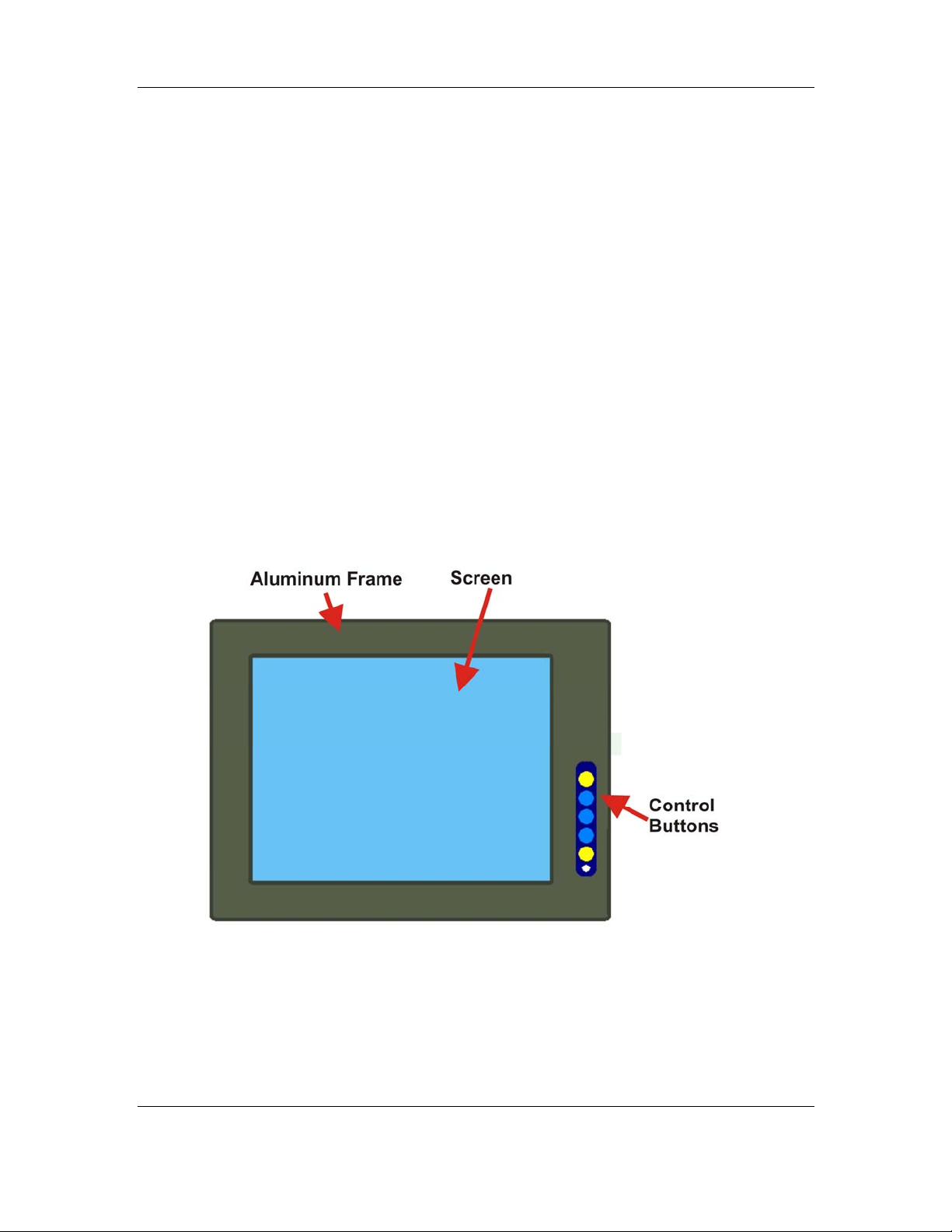
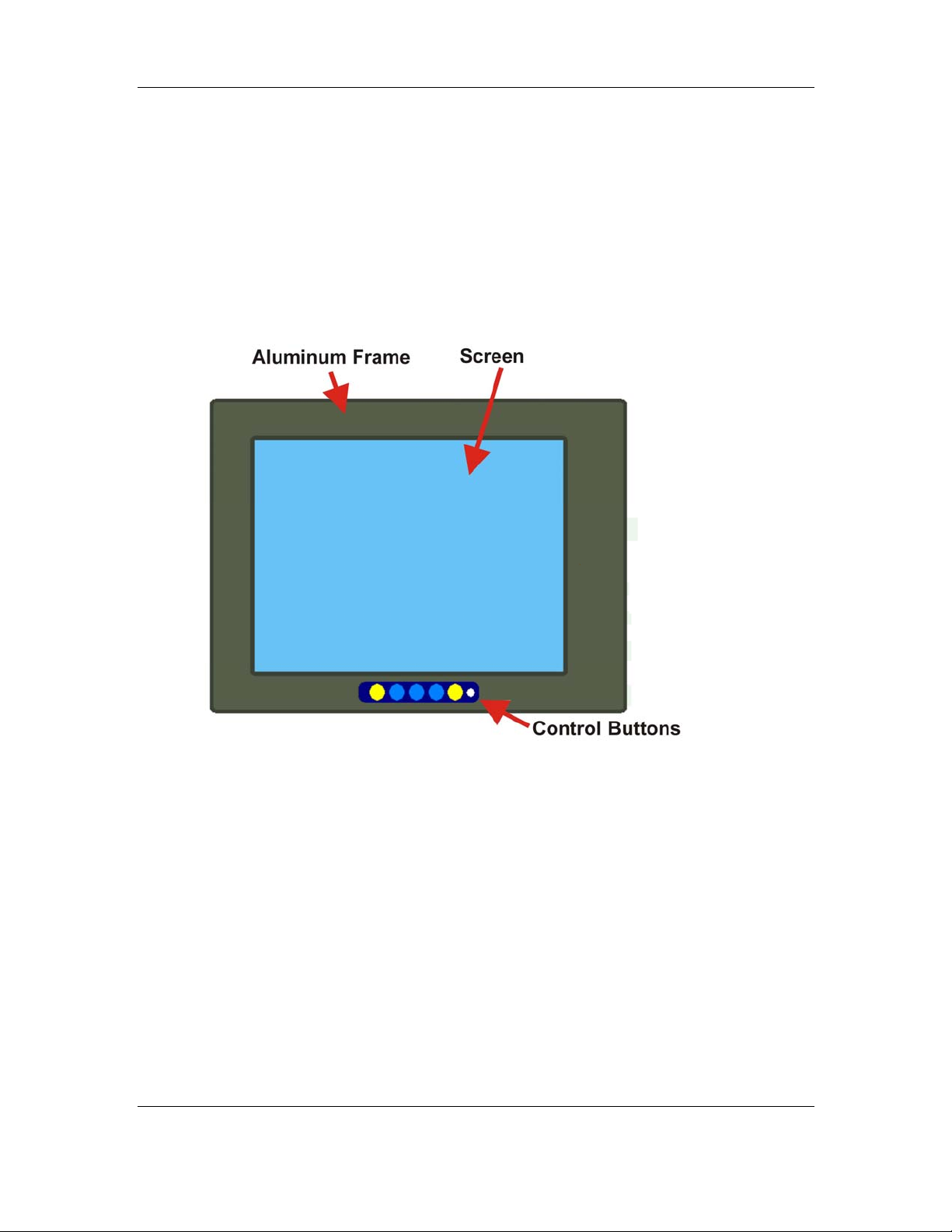
1.3.1 Front View
The front of the MPD Series industrial monitor is a flat panel TFT LCD screen surrounded
by an aluminum frame. A control button panel (OSD), if available, is located either
vertically on the right side of the frame or horizontally along the bottom of the frame with
the following control buttons:
LCD On/Off
Auto
Left
Right
Menu
The OSD panel also has one power LED.
Figure 1-1 shows a typical monitor front view.
Figure 1-1: Typical Monitor Front View
CyberResearch, Inc. 5
25 Business Park Drive P: (203) 643-5000; F: (203) 643-5001
Branford, CT USA www.cyberresearch.com
Page 30
MPD Series CyberResearch® Industrial Monitors
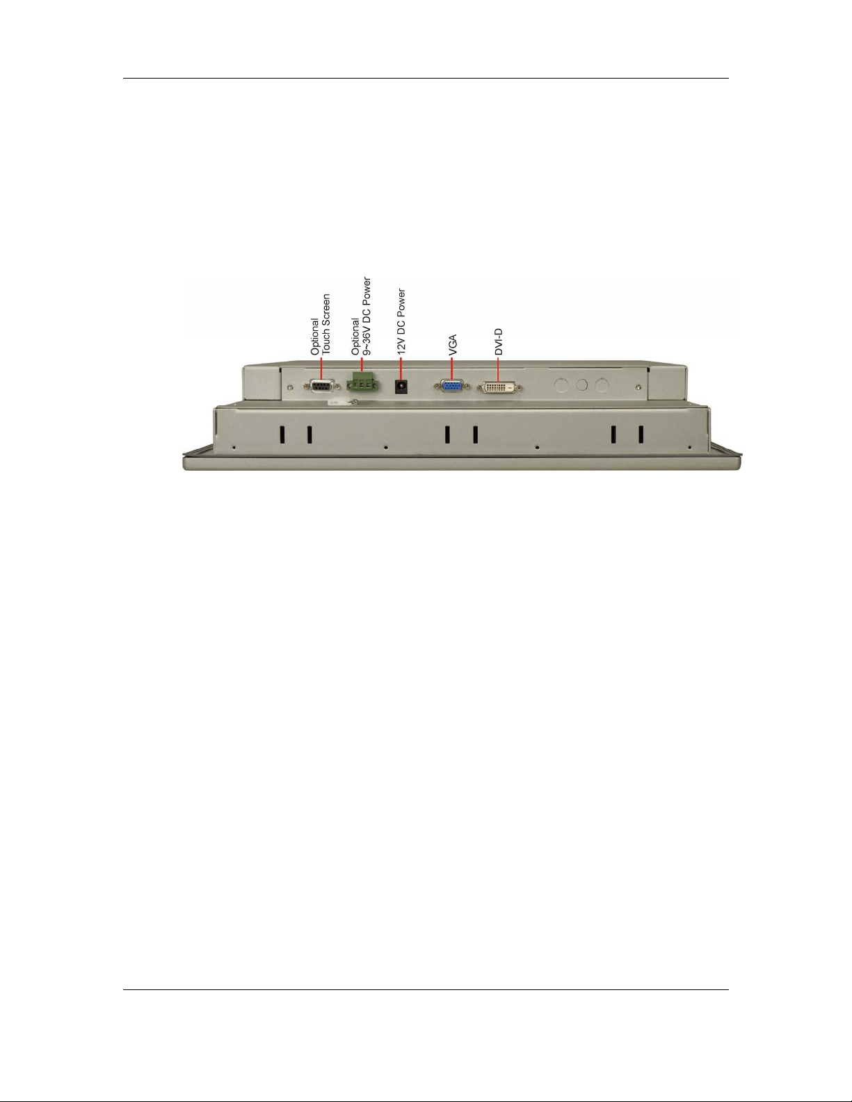
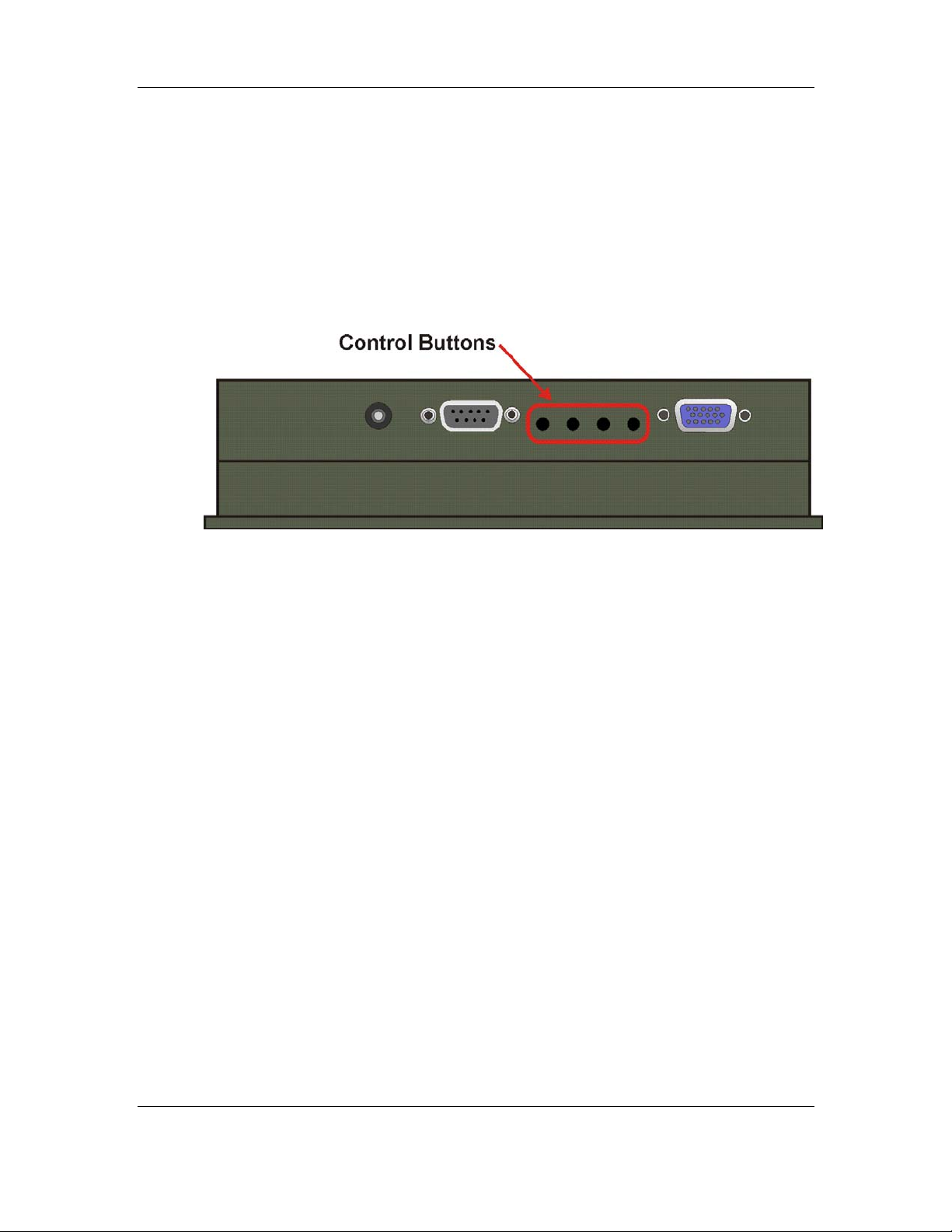
1.3.2 Bottom Panel View
Figure 1-2 shows the bottom panel of the MPD 19AG monitor. Other models may include
or exclude additional connectors. Refer to Section 2.3 for listings of monitors and their
connectors. All connectors are fully described in Section 5.4.
Figure 1-2: Typical Bottom Panel View
6 ©Copyright 2008 CyberResearch, Inc.
Page 31

CyberResearch® Industrial Monitors MPD Series
1.3.3 LCD Controller
The MPD Series industrial monitor LCD Controller provides a wide variety of control
interfaces, receiving and managing signals from a CPU card through cabling. Figure 1-3
shows the 5300 LCD Controller as a sample of a typical LCD Controller for the MPD
Series industrial monitor. Refer to Chapter 4 for a complete description of LCD Controllers
and their connectors.
Figure 1-3: 5300 LCD Controller
CyberResearch, Inc. 7
25 Business Park Drive P: (203) 643-5000; F: (203) 643-5001
Branford, CT USA www.cyberresearch.com
Page 32

MPD Series CyberResearch® Industrial Monitors
1.4 Series Specifications
Table 1-1 shows the MPD Series specifications.
Model MPD 06AG MPD 08AG MPD 10AG MPD 12AG MPD 15AG MPD 17AG MPD 19AG
LCD Size 6.5” 8.4” 10.4” 12.1” 12” 17” 19”
Input
Interface
Max.
Resolution
Brightness
(cd/m2)
Contrast 550:1 500:1 500:1 500:1 400:1 500:1 700:1
LCD Color 262K 262K 262K 262K 262K 16.2M 16.2M
Pixel Pitch (mm) 0.207 0.213 0.264 0.3075 0.297 0.264 0.294
Front Frame Aluminum Aluminum Aluminum Aluminum Aluminum Aluminum Aluminum
Chassis
View Angle
(H / V)
LCD Controller 9350 5350 5350 5300 5300 5300 5300
Power Adapter 25W 25W 25W 45W 45W 45W 45W
VGA VGA VGA
640x480 800x600 800x600 800x600 1024x768 1280x1024 1280x1024
300 300 300 300 250 250 250
Heavy-duty
steel
140/120 130/110 120/100 140/110 120/100 140/130 140/130
Heavy-duty
steel
Heavy-duty
steel
VGA
DVI-D
Heavy-duty
steel
VGA
DVI-D
Heavy-duty
steel
VGA
DVI-D
Heavy-duty
steel
VGA
DVI-D
Heavy-duty
steel
OSD function Yes Yes Yes Yes Yes Yes Yes
Panel
Wall
Rack
Mounting
DIN
Arm
Stand
Color Silver Silver Silver Silver Silver Silver Silver
183 x
Dimension
143 x
(WxHxD) (mm)
41
Operation 0~50°C 0~50°C 0~50°C 0~50°C 0~50°C 0~50°C 0~50°C
Panel
Wall
Rack
DIN
Arm
Stand
244 x
178 x
49
Panel
Wall
Rack
Arm
Stand
312 x
242 x
53
Panel
Wall
Rack
Arm
Stand
340 x
260 x
58
Panel
Wall
Rack
Arm
Stand
410 x
309 x
65.1
Panel
Wall
Rack
Arm
Stand
452.0 x
356.0 x
65.2
Panel
Wall
Rack
Arm
482 x
399 x
73
8 ©Copyright 2008 CyberResearch, Inc.
Page 33

CyberResearch® Industrial Monitors MPD Series
Model MPD 06AG MPD 08AG MPD 10AG MPD 12AG MPD 15AG MPD 17AG MPD 19AG
Temperature
IP Level IP 65 IP 65 IP 65 IP 65 IP 65 IP 65 IP 65
N/G Weight 1kg 1.8kg 3kg 3.8kg 6kg 8.6kg 10kg
Table 1-1: MPD Series Specifications
1.5 Certifications
All MPD Series industrial monitor models comply with the following international
standards:
RoHS
IP65
For a more detailed description of these standards, please refer to Appendix A.
CyberResearch, Inc. 9
25 Business Park Drive P: (203) 643-5000; F: (203) 643-5001
Branford, CT USA www.cyberresearch.com
Page 34

MPD Series CyberResearch® Industrial Monitors
Intentionally Blank
10 ©Copyright 2008 CyberResearch, Inc.
Page 35

CyberResearch® Industrial Monitors MPD Series
Chapter
2
2 Mechanical Overview
CyberResearch, Inc. 11
25 Business Park Drive P: (203) 643-5000; F: (203) 643-5001
Branford, CT USA www.cyberresearch.com
Page 36

MPD Series CyberResearch® Industrial Monitors
2.1 Introduction
This chapter describes the general mechanical overview of the MPD Series monitors
including front and bottom panel variations, available interfaces and overall dimensions.
2.2 Front Panel
The front panel of the MPD Series industrial monitor is comprised of a TFT LCD in an
aluminum frame with an OSD control panel.
2.2.1 Front Panel Variants
Table 2-1 shows the three front panel variants for the MPD Series industrial monitor.
Model OSD Control Panel Location
MPD 17AG, MPD 15AG,
MPD 12AG, MPD 10AG,
MPD 08AG
MPD 19AG
MPD 06AG
Table 2-1: Front Panel Variants
Vertically along the right side
of the aluminum frame
Horizontally along the bottom
of the aluminum frame
In line along the bottom
of the rear panel
Variant
Number
1
2
3
12 ©Copyright 2008 CyberResearch, Inc.
Page 37
CyberResearch® Industrial Monitors MPD Series
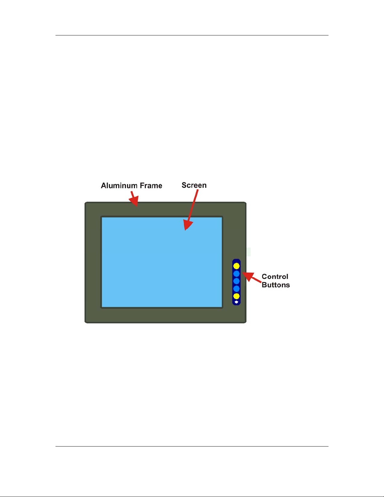
2.2.2 Front Panel Variant 1
The following models of the MPD Series industrial monitor have an OSD control panel
located vertically along the right side of the aluminum frame:
MPD 17AG
MPD 15AG
MPD 12AG
MPD 10AG
MPD 08AG
Figure 2-1 shows the location of the front panel variant 1 OSD controls.
Figure 2-1: Front Panel Variant 1
CyberResearch, Inc. 13
25 Business Park Drive P: (203) 643-5000; F: (203) 643-5001
Branford, CT USA www.cyberresearch.com
Page 38
MPD Series CyberResearch® Industrial Monitors
2.2.3 Front Panel Variant 2
The following model of the MPD Series industrial monitor has an OSD control panel
located horizontally along the bottom of the aluminum frame:
MPD 19AG
Figure 2-2 shows the location of the front panel variant 2 OSD controls.
Figure 2-2: Front Panel Variant 2
14 ©Copyright 2008 CyberResearch, Inc.
Page 39
CyberResearch® Industrial Monitors MPD Series
2.2.4 Front Panel Variant 3
The following model of the MPD Series industrial monitor has an OSD control panel
located in-line along the bottom of the aluminum frame:
MPD 06AG
Figure 2-3 shows the location of the front panel variant 3 OSD controls.
Figure 2-3: Front Panel Variant 3
2.3 Bottom Panel
All peripheral device connectors are located on the bottom panel of the MPD Series
industrial monitor. The following sections describe the bottom panel variants and their
associated connectors.
2.3.1 Available Connectors
There are a number of bottom panel peripheral device connectors available for the MPD
Series industrial monitor.
VGA connector
DVI-D connector
12V power connector
RS-232 serial connector
USB connector
CyberResearch, Inc. 15
25 Business Park Drive P: (203) 643-5000; F: (203) 643-5001
Branford, CT USA www.cyberresearch.com
Page 40

MPD Series CyberResearch® Industrial Monitors
2.3.2 MPD 06AG Connectors
The following is a list of the bottom panel peripheral device connectors used on the MPD
06AG series industrial monitor.
VGA connector
12V power connector
RS-232 serial connector (-TR models only)
2.3.3 MPD 08AG Connectors
The following is a list of the bottom panel peripheral device connectors used on the MPD
08AG series industrial monitor.
VGA connector
12V power connector
RS-232 serial connector (-TR models only)
2.3.4 MPD 10AG Connectors
The following is a list of the bottom panel peripheral device connectors used on the MPD
10AG series industrial monitor.
VGA connector
12V power connector
RS-232 serial connector (-TR models only)
16 ©Copyright 2008 CyberResearch, Inc.
Page 41

CyberResearch® Industrial Monitors MPD Series
2.3.5 MPD 12AG Connectors
The following is a list of the bottom panel peripheral device connectors used on the MPD
12AG series industrial monitor.
VGA connector
DVI-D connector
12V power connector
RS-232 serial connector (-TR models only)
USB connector (-TRU models only)
2.3.6 MPD 15AG Connectors
The following is a list of the bottom panel peripheral device connectors used on the MPD
15AG series industrial monitor.
VGA connector
DVI-D connector
12V power connector
RS-232 serial connector (-TR models only)
2.3.7 MPD 17AG Connectors
The following is a list of the bottom panel peripheral device connectors used on the MPD
17AG series industrial monitor.
VGA connector
DVI-D connector
12V power connector
RS-232 serial connector (-TR models only)
CyberResearch, Inc. 17
25 Business Park Drive P: (203) 643-5000; F: (203) 643-5001
Branford, CT USA www.cyberresearch.com
Page 42

MPD Series CyberResearch® Industrial Monitors
2.3.8 MPD 19AG Connectors
The following is a list of the bottom panel peripheral device connectors used on the MPD
19AG series industrial monitor.
VGA connector
DVI-D connector
12V power connector
RS-232 serial connector (-TR models only)
2.4 Physical Dimensions
The following sections describe the physical dimensions for each model of the MPD
Series industrial monitor.
2.4.1 General Physical Dimensions
General physical dimensions for the MPD Series industrial monitors are shown in
Table 2-2.
Model Width
(mm)
MPD 19AG 482 399 73
MPD 17AG 452 356 65.2
MPD 15AG 410 309 65.1
MPD 12AG 340 260 58
MPD 10AG 312 242 53
MPD 08AG 244 178 49
MPD 06AG 183 143 41
Height
(mm)
Table 2-2: General Physical Dimensions
Depth
(mm)
18 ©Copyright 2008 CyberResearch, Inc.
Page 43
CyberResearch® Industrial Monitors MPD Series
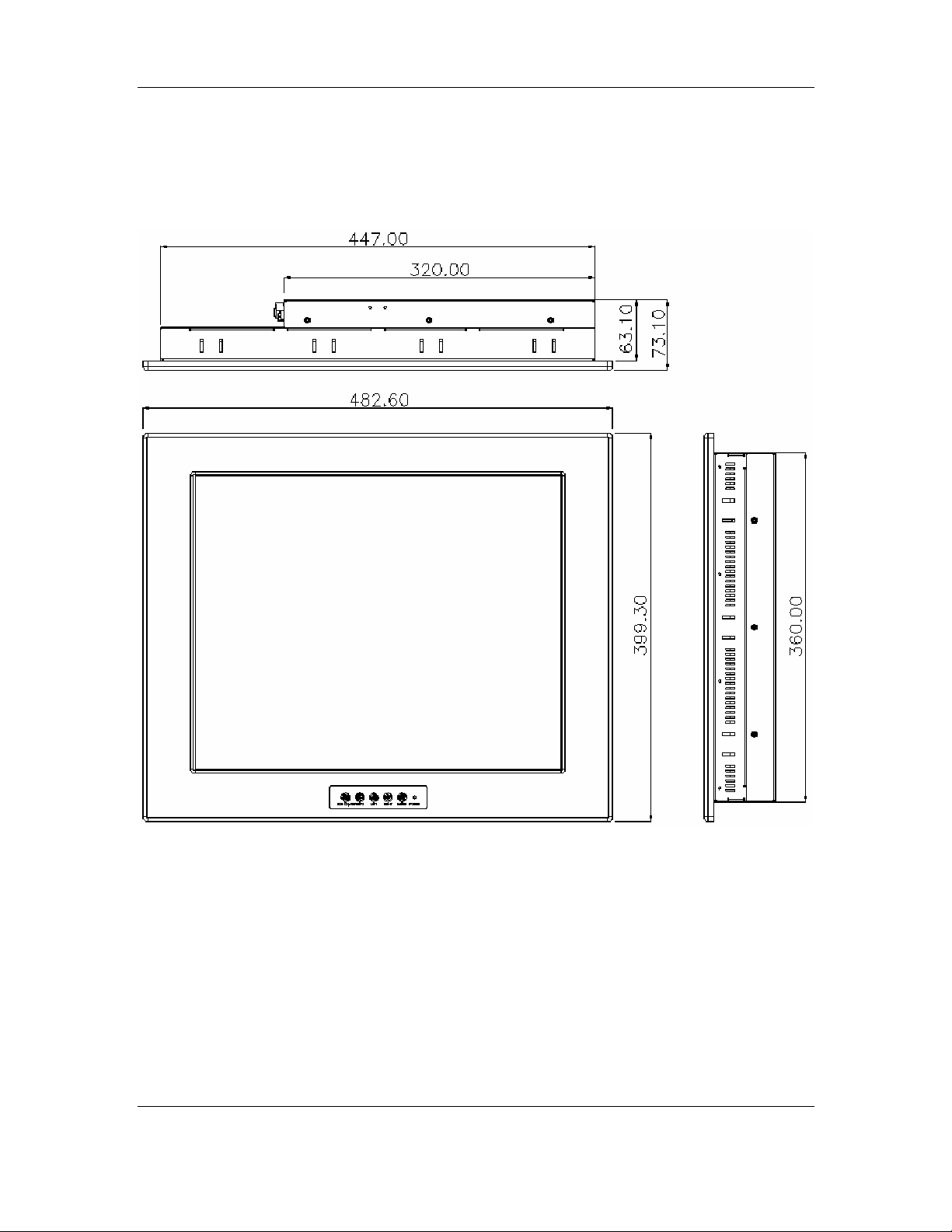
2.4.2 MPD 19AG Physical Dimensions
The physical dimensions of the MPD 19AG are shown in Figure 2-4.
Figure 2-4: MPD 19AG Physical Dimensions (millimeters)
CyberResearch, Inc. 19
25 Business Park Drive P: (203) 643-5000; F: (203) 643-5001
Branford, CT USA www.cyberresearch.com
Page 44

MPD Series CyberResearch® Industrial Monitors
2.4.3 MPD 17AG Physical Dimensions
The physical dimensions of the MPD 17AG are shown in Figure 2-5.
Figure 2-5: MPD 17AG Physical Dimensions (millimeters)
20 ©Copyright 2008 CyberResearch, Inc.
Page 45

CyberResearch® Industrial Monitors MPD Series
2.4.4 MPD 15AG Physical Dimensions
The physical dimensions of the MPD 15AG are shown in Figure 2-6.
Figure 2-6: MPD 15AG Physical Dimensions (millimeters)
CyberResearch, Inc. 21
25 Business Park Drive P: (203) 643-5000; F: (203) 643-5001
Branford, CT USA www.cyberresearch.com
Page 46

MPD Series CyberResearch® Industrial Monitors
2.4.5 MPD 12AG Physical Dimensions
The physical dimensions of the MPD 12AG are shown in Figure 2-7.
Figure 2-7: MPD 12AG Physical Dimensions (millimeters)
22 ©Copyright 2008 CyberResearch, Inc.
Page 47

CyberResearch® Industrial Monitors MPD Series
2.4.6 MPD 10AG Physical Dimensions
The physical dimensions of the MPD 10AG are shown in Figure 2-8.
Figure 2-8: MPD 10AG Physical Dimensions (millimeters)
CyberResearch, Inc. 23
25 Business Park Drive P: (203) 643-5000; F: (203) 643-5001
Branford, CT USA www.cyberresearch.com
Page 48
MPD Series CyberResearch® Industrial Monitors
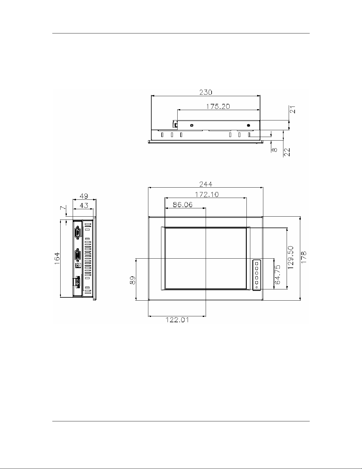
2.4.7 MPD 08AG Physical Dimensions
The physical dimensions of the MPD 08AG are shown in Figure 2-9.
Figure 2-9: MPD 08AG Physical Dimensions (millimeters)
24 ©Copyright 2008 CyberResearch, Inc.
Page 49

CyberResearch® Industrial Monitors MPD Series
2.4.8 MPD 06AG Physical Dimensions
The physical dimensions of the MPD 06AG are shown in Figure 2-10.
Figure 2-10: MPD 06AG Physical Dimensions (millimeters)
CyberResearch, Inc. 25
25 Business Park Drive P: (203) 643-5000; F: (203) 643-5001
Branford, CT USA www.cyberresearch.com
Page 50
MPD Series CyberResearch® Industrial Monitors
2.5 Optional Mounting Kits
The following sections describe the various optional mounting kits available for each
model of the MPD Series industrial monitor. Refer to Section 5.5 for detailed instructions
on the different mounting methods for the monitors.
2.5.1 MPD 06AG Mounting Kits
Table 2-3 lists the mounting kits available for the MPD 06AG monitor.
Model MPD 06AG
Panel Mounting Kit Included
Rack Mounting Kit MPD 06GRK
Wall Mounting Kit MPD 06GWK
DIN Mounting Kit MPD 06GDK
Table 2-3: MPD 06AG Mounting
Kits
2.5.2 MPD 08AG Mounting Kits
Table 2-4 lists the mounting kits available for the MPD 08AG monitor.
Model MPD 08AG
Panel Mounting Kit MPD 08GPK
Rack Mounting Kit MPD 08GRK
Wall Mounting Kit MPD 08GWK
DIN Mounting Kit MPD 08GDK
Table 2-4: MPD 08AG Mounting
Kits
26 ©Copyright 2008 CyberResearch, Inc.
Page 51
CyberResearch® Industrial Monitors MPD Series
2.5.3 MPD 10AG Mounting Kits
Table 2-5 lists the mounting kits available for the MPD 10AG monitor.
Model MPD 10AG
Panel Mounting Kit MPD 10GPK
Rack Mounting Kit MPD 10GRK
Wall Mounting Kit MPD 10GWK
Table 2-5: MPD 10AG Mounting
Kits
2.5.4 MPD 12AG Mounting Kits
Table 2-6 lists the mounting kits available for the MPD 12AG monitor.
Model MPD 12AG
Panel Mounting Kit MPD 10GPK
Rack Mounting Kit MPD 10GRK
Wall Mounting Kit MPD 10GWK
Table 2-6: MPD 12AG Mounting
Kits
CyberResearch, Inc. 27
25 Business Park Drive P: (203) 643-5000; F: (203) 643-5001
Branford, CT USA www.cyberresearch.com
Page 52
MPD Series CyberResearch® Industrial Monitors
2.5.5 MPD 15AG Mounting Kits
Table 2-7 lists the mounting kits available for the MPD 15AG monitor.
Model MPD 15AG
Panel Mounting Kit MPD 15GPK
Rack Mounting Kit MPD 15GRK
Wall Mounting Kit MPD 15GWK
Table 2-7: MPD 15AG Mounting
Kits
2.5.6 MPD 17AG Mounting Kits
Table 2-8 lists the mounting kits available for the MPD 17AG monitor.
Model MPD 17AG
Panel Mounting Kit MPD 17GPK
Rack Mounting Kit MPD 17GRK
Wall Mounting Kit MPD 17GWK
Table 2-8: MPD 17AG Mounting
Kits
28 ©Copyright 2008 CyberResearch, Inc.
Page 53

CyberResearch® Industrial Monitors MPD Series
2.5.7 MPD 19AG Mounting Kits
Table 2-9 lists the mounting kits available for the MPD 19AG monitor.
Model MPD 19AG
Panel Mounting Kit MPD 19GPK
Rack Mounting Kit MPD 19GRK
Wall Mounting Kit MPD 19GWK
Table 2-9: MPD 19AG Mounting
Kits
2.6 Mounting Options
Each MPD Series industrial monitor has a number of mounting holes or slots located on
the back side of the aluminum frame or on the rear panel for mounting the monitor to a
rack, panel, cabinet, DIN rail, wall, arm or stand. The following sections describe the
various mounting methods or each model of the MPD Series industrial monitor.
2.6.1 Panel Mounting
Each model of the MPD Series industrial monitor has a series of mounting slots located on
the top and bottom panel for mounting the monitor to a panel.
NOTE:
The MPD 06AG monitor requires two special mounting brackets for installation
into a panel. Refer to Section 5.5.1.2 for details.
Figure 2-11 shows a typical panel installation.
CyberResearch, Inc. 29
25 Business Park Drive P: (203) 643-5000; F: (203) 643-5001
Branford, CT USA www.cyberresearch.com
Page 54
MPD Series CyberResearch® Industrial Monitors
Figure 2-11: Typical Panel Mounting
Table 2-10 lists the number of mounting clamps required to mount the monitor to a panel.
Model Mounting Clamps
MPD 19AG 14
MPD 17AG 10
MPD 15AG 10
MPD 12AG 10
MPD 10AG 10
MPD 08AG 8
Table 2-10: Panel Mounting Clamps
30 ©Copyright 2008 CyberResearch, Inc.
Page 55
CyberResearch® Industrial Monitors MPD Series
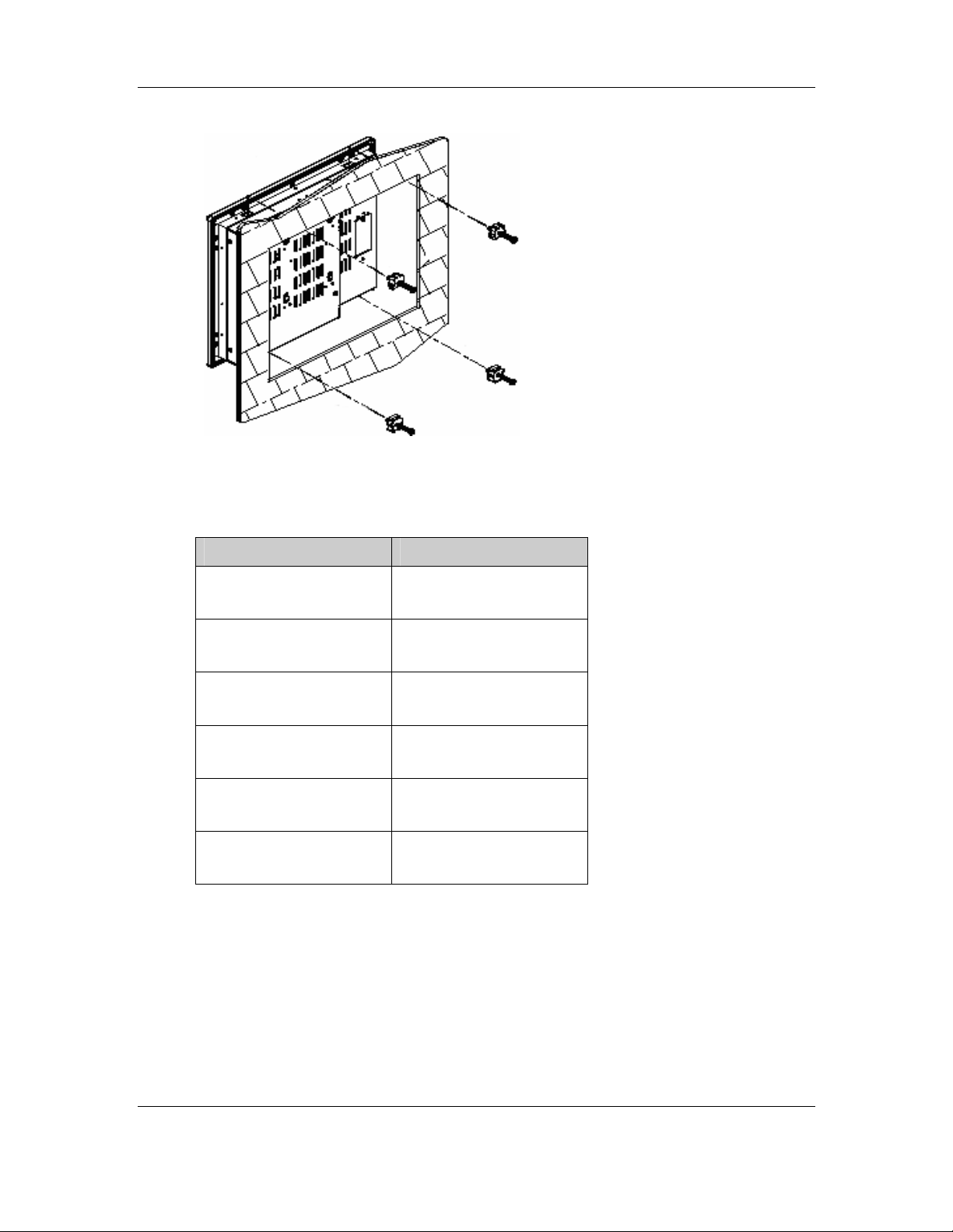
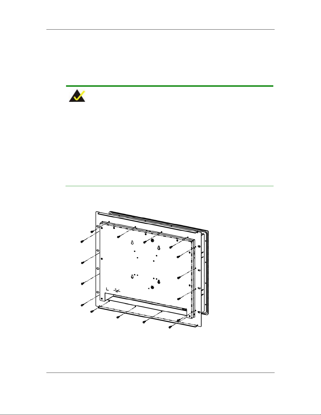
2.6.2 Rack and Cabinet Mounting
Each model of the MPD Series industrial monitor has a series of holes located on the rear
of the front panel for mounting the monitor to a rack or cabinet.
NOTE:
1. The MPD 19AG monitor requires two special mounting brackets for
installation into a rack or cabinet. Refer to Section 5.5.2.2 for details.
2. The MPD 08AG monitor uses panel mounting clamps for installation into a
rack or cabinet. Refer to Section 5.5.1.1 for details.
3. The MPD 06AG monitor uses panel mounting clamps for installation into a
rack or cabinet. Refer to Section 5.5.1.2 for details.
Figure 2-12 shows a typical rack or cabinet installation.
Figure 2-12: Typical Rack or Cabinet Mounting
CyberResearch, Inc. 31
25 Business Park Drive P: (203) 643-5000; F: (203) 643-5001
Branford, CT USA www.cyberresearch.com
Page 56
MPD Series CyberResearch® Industrial Monitors
Table 2-11 lists the number of holes each monitor has for mounting to a rack or cabinet.
Model Holes
MPD 17AG 16
MPD 15AG 12
MPD 12AG 8
MPD 10AG 10
Table 2-11: Rack Mounting Clamps
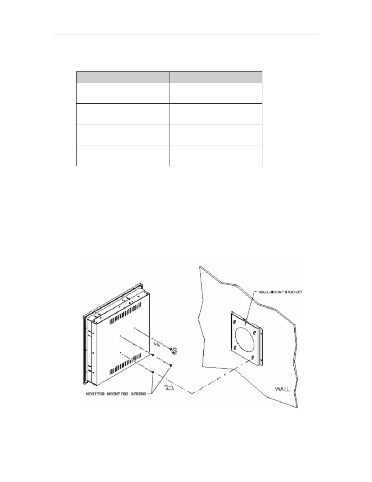
2.6.3 Wall Mounting
Each model of the MPD Series industrial monitor has four holes located on the rear panel
for mounting the monitor to a wall. Figure 2-13 shows the typical methods for wall
mounting.
Figure 2-13: Typical Wall Mounting
32 ©Copyright 2008 CyberResearch, Inc.
Page 57

CyberResearch® Industrial Monitors MPD Series
2.6.4 DIN Rail Mounting
The MPD 08AG and MPD 06AG have four holes located on the rear panel for mounting
the monitor to a DIN rail clamp.
Figure 2-14 shows a typical DIN rail mounting bracket.
Figure 2-14: Typical DIN Rail Mounting
CyberResearch, Inc. 33
25 Business Park Drive P: (203) 643-5000; F: (203) 643-5001
Branford, CT USA www.cyberresearch.com
Page 58
MPD Series CyberResearch® Industrial Monitors
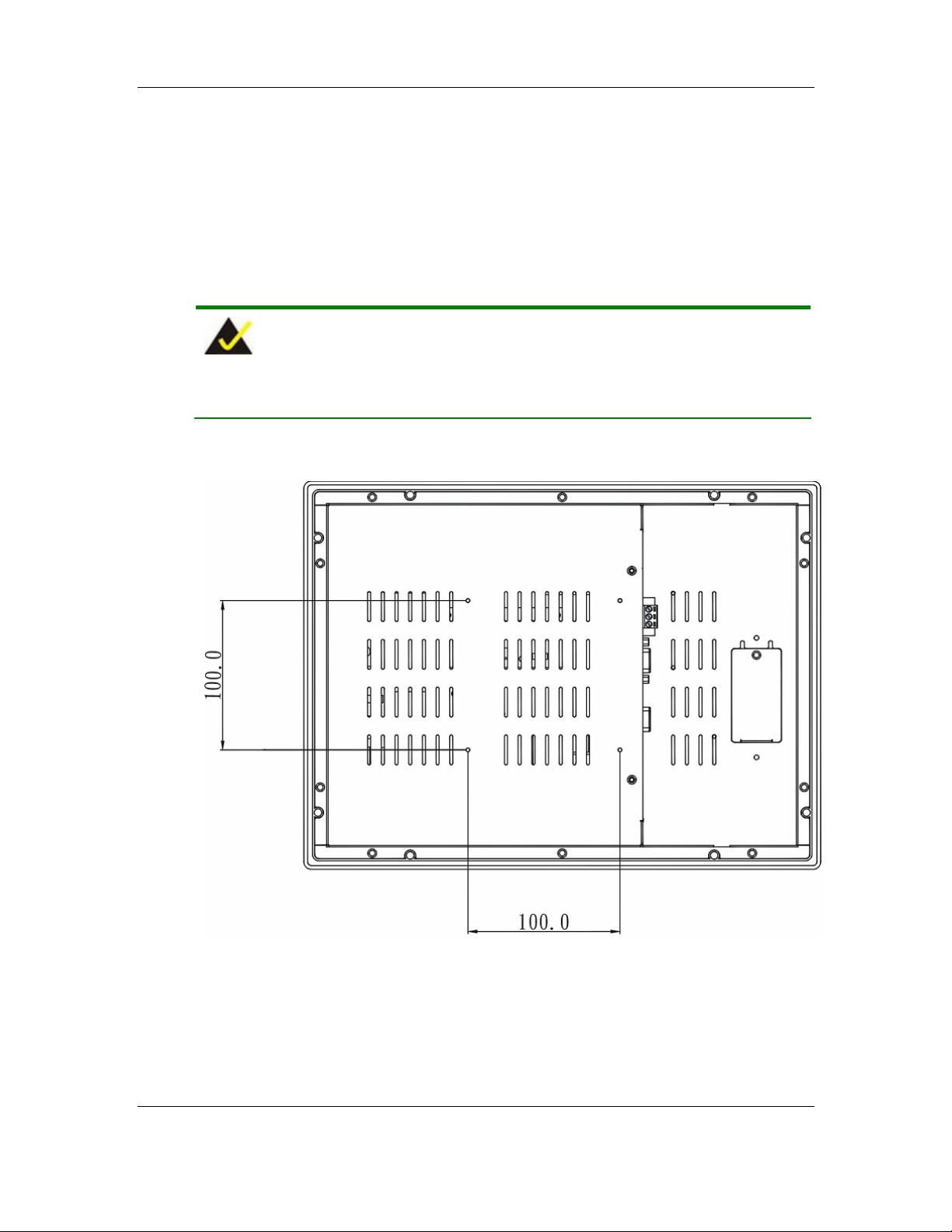
2.6.5 Monitor Arm or Stand Mounting
Most models of the MPD Series industrial monitor have four or eight Video Electronics
Standards Association (VESA) standard holes located on the rear panel for mounting the
monitor to a monitor arm or stand.
NOTE:
There is no monitor stand available for the MPD 19AG monitor.
Figure 2-15 shows a typical monitor arm or stand mounting.
Figure 2-15: Typical Monitor Arm or Stand Mounting
34 ©Copyright 2008 CyberResearch, Inc.
Page 59

CyberResearch® Industrial Monitors MPD Series
Chapter
3
3 LCD and Touch Panel
Specifications
CyberResearch, Inc. 35
25 Business Park Drive P: (203) 643-5000; F: (203) 643-5001
Branford, CT USA www.cyberresearch.com
Page 60

MPD Series CyberResearch® Industrial Monitors
3.1 LCD Specifications
3.1.1 LCD Overview
The MPD Series industrial monitors use the following LCD panels.
MPD 19AG: AUO M190EG02
MPD 17AG: AUO M170EG01
MPD 15AG: AUO G150XG01
MPD 12AG: AUO G121SN01
MPD 10AG: AUO G104SN03
MPD 08AG: AUO G084SN03
MPD 06AG: Toshiba LTA065B0D0F
Detailed specifications for the LCD screens are listed in the following sections.
36 ©Copyright 2008 CyberResearch, Inc.
Page 61

CyberResearch® Industrial Monitors MPD Series
3.1.2 MPD 19AG LCD Specifications
Table 3-1 lists the MPD 19AG LCD specifications.
Model MPD 19AG
Size 19”
MFR/Model AUO/M190EG02
Resolution SXGA (1280 x 1024)
Active Area (mm) 376.3 x 301.1
Pixel Pitch (mm) 0.294
Mode TN
Number of Colors 16.2M
Color Saturation (NTSC%) 72
View Angle (H/V) 160 / 160
Brightness (cd/m2) 250
Contrast Ratio 700:1
Response Time (ms) (at 25C) 6
Power Consumption (W) 28
Interface 2ch LVDS
Supply Voltage (V) 5
Backlight 4 CCFL
Lamp Life (hrs) 50,000
Table 3-1: MPD 19AG LCD Specifications
CyberResearch, Inc. 37
25 Business Park Drive P: (203) 643-5000; F: (203) 643-5001
Branford, CT USA www.cyberresearch.com
Page 62

MPD Series CyberResearch® Industrial Monitors
3.1.3 MPD 17AG LCD Specifications
Table 3-2 lists the MPD 17AG LCD specifications.
Model MPD 17AG
Size 17”
MFR/Model AUO/M170EG01
Resolution SXGA (1280 x 1024)
Active Area (mm) 337.9 x 270.3
Pixel Pitch (mm) 0.264
Mode TN
Number of Colors 16.2M
Color Saturation (NTSC%) 72
View Angle (H/V) 140/130
Brightness (cd/m2) 250
Contrast Ratio 500:1
Response Time (ms) (at 25C) 8
Power Consumption (W) 25.8
Interface 2ch LVDS
Supply Voltage (V) 5
Backlight 4 CCFL
Lamp Life (hrs) 50,000
Table 3-2: MPD 17AG LCD Specifications
38 ©Copyright 2008 CyberResearch, Inc.
Page 63

CyberResearch® Industrial Monitors MPD Series
3.1.4 MPD 15AG LCD Specifications
Table 3-3 lists the MPD 15AG LCD specifications.
Model MPD 15AG
Size 15”
MFR/Model AUO/G150XG01
XGA (1024 x
Resolution
Active Area (mm) 304.1 x 228.1
Pixel Pitch (mm) 0.297
Mode TN
Number of Colors 262K
Color Saturation (NTSC%) 60
View Angle (H/V) 130/120
Brightness (cd/m2) 250
Contrast Ratio 500:1
Response Time (ms) (at 25C) 12
Power Consumption (W) 11.5
Interface 1ch LVDS
Supply Voltage (V) 3.3
Backlight 2 CCFL
Lamp Life (hrs) 50000
768)
Table 3-3: MPD 15AG LCD Specifications
CyberResearch, Inc. 39
25 Business Park Drive P: (203) 643-5000; F: (203) 643-5001
Branford, CT USA www.cyberresearch.com
Page 64

MPD Series CyberResearch® Industrial Monitors
3.1.5 MPD 12AG LCD Specifications
Table 3-4 lists the MPD 12AG LCD specifications.
Model MPD 12AG
Size 12.1”
MFR/Model AUO/G121SN01
SVGA (800 x
Resolution
Active Area (mm) 246.0 x 184.5
Pixel Pitch (mm) 0.307
Mode TN
Number of Colors 62K
Color Saturation (NTSC%) 55
View Angle (H/V) 150/110
Brightness (cd/m2) 300
Contrast Ratio 500:1
Response Time (ms) (at 25C) 35
Power Consumption (W) 7.3
Interface 1ch LVDS
Supply Voltage (V) 3.3
Backlight 2 CCFL
Lamp Life (hrs) 50000
600)
Table 3-4: MPD 12AG LCD Specifications
40 ©Copyright 2008 CyberResearch, Inc.
Page 65

CyberResearch® Industrial Monitors MPD Series
3.1.6 MPD 10AG LCD Specifications
Table 3-5 lists the MPD 10AG LCD specifications.
Model MPD 10AG
Size 10.4”
MFR/Model AUO/G104SN03
Resolution SVGA (800 x 600)
Active Area (mm) 211.2 x 158.4
Pixel Pitch (mm) 0.264
Mode TN
Number of Colors 262K
Color Saturation (NTSC%) 45
View Angle (H/V) 140 / 110
Brightness (cd/m2) 300
Contrast Ratio 500:1
Response Time (ms) (at 25C) 35
Power Consumption (W) 2.52
Interface 1ch LVDS
Supply Voltage (V) 3.3
Backlight 1 CCFL
Lamp Life (hrs) 20000
Table 3-5: MPD 10AG LCD Specifications
CyberResearch, Inc. 41
25 Business Park Drive P: (203) 643-5000; F: (203) 643-5001
Branford, CT USA www.cyberresearch.com
Page 66

MPD Series CyberResearch® Industrial Monitors
3.1.7 MPD 08AG LCD Specifications
Table 3-6 lists the MPD 08AG LCD specifications.
Model MPD 08AG
Size 8.4”
MFR/Model AUO/G084SN03
Resolution SVGA (800 x 600)
Active Area (mm) 170.4 x 127.8
Pixel Pitch (mm) 0.213
Mode TN
Number of Colors 262K
Color Saturation (NTSC%) 45
View Angle (H/V) 130 / 110
Brightness (cd/m2) 300
Contrast Ratio 500:1
Response Time (ms) (at 25C) 35
Power Consumption (W) 3.3
Interface 1ch LVDS
Supply Voltage (V) 3.3
Backlight 1 CCFL
Lamp Life (hrs) 20000
Table 3-6: MPD 08AG LCD Specifications
42 ©Copyright 2008 CyberResearch, Inc.
Page 67
CyberResearch® Industrial Monitors MPD Series
3.1.8 MPD 06AG LCD Specifications
Table 3-7 lists the MPD 06AG LCD specifications.
Model MPD 06AG
Size 6.5”
MFR/Model Toshiba/LTA065B0D0F
Resolution VGA (640 x 480)
Active Area (mm) 132.48 x 99.36
Pixel Pitch (mm) 0.207
Mode
Number of Colors 262K
Color Saturation (NTSC%)
View Angle (H/V) 140/120
Brightness (cd/m2) 300
Contrast Ratio 500:1
Response Time (ms) (at 25C) 25
Power Consumption (W) 4.2
Interface
Supply Voltage (V) 3.3
Backlight 2 CCFL
Lamp Life (hrs) 50000
Table 3-7: MPD 06AG LCD Specifications
CyberResearch, Inc. 43
25 Business Park Drive P: (203) 643-5000; F: (203) 643-5001
Branford, CT USA www.cyberresearch.com
Page 68

MPD Series CyberResearch® Industrial Monitors
3.2 Optional Touch Panels
CyberResearch offers optional touch panels for the MPD Series industrial monitors with
the following features:
Small border customized design
All size touch panel design
Customized activation force and palm rejection
Customized optical characteristics
High reliability and durability in the field
3.2.1 Touch Panel Models
Table 3-8 lists the MPD Series industrial monitors and their associated touch panels.
Model Touch Panel
MPD 19AG PanJit 1190503A
MPD 17AG PanJit 1171505A
MPD 15AG PanJit 1150508B
MPD 12AG PanJit 1121505B
MPD 10AG PanJit 1104502A
MPD 08AG PanJit 1084403B
MPD 06AG PanJit 1065403C
Table 3-8: Touch Panel Models
44 ©Copyright 2008 CyberResearch, Inc.
Page 69
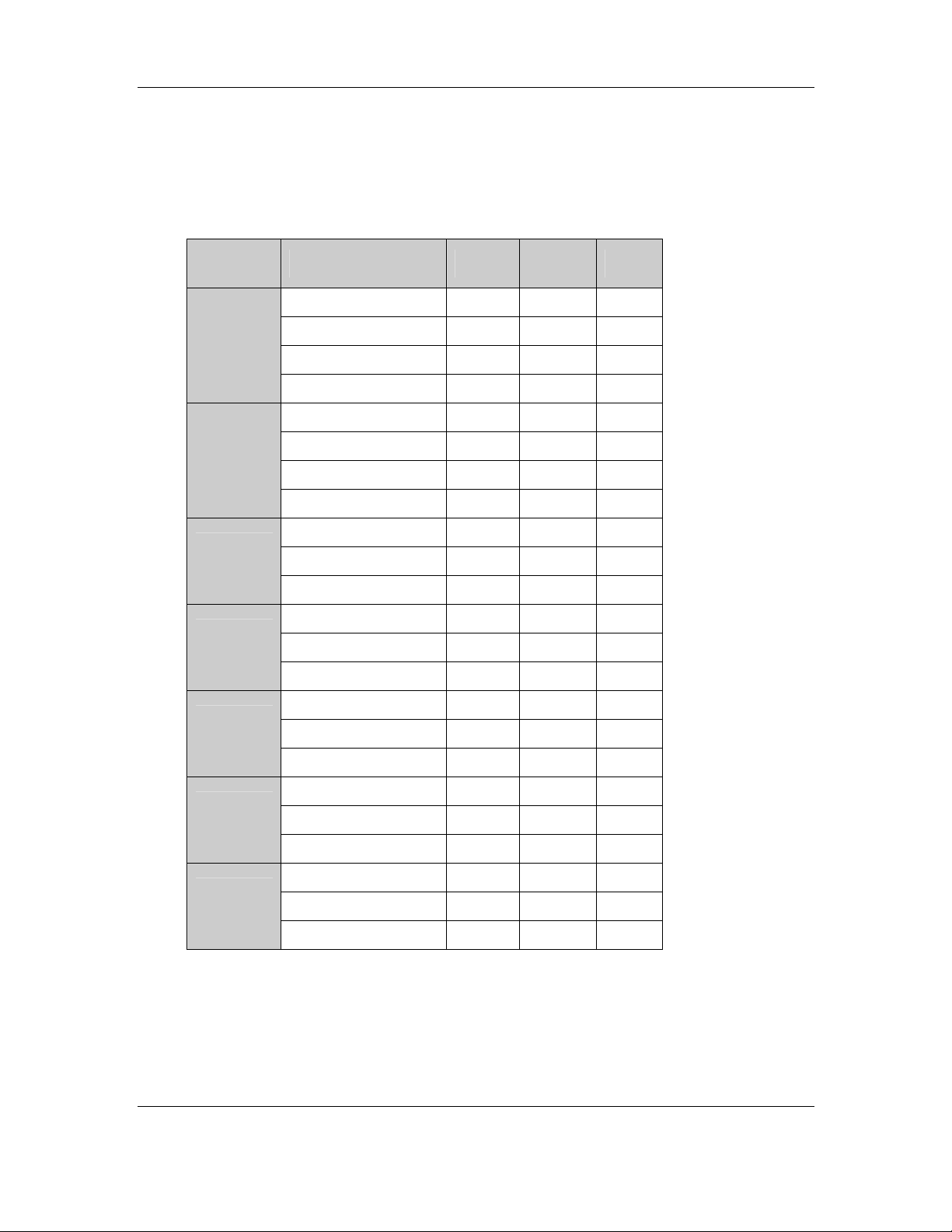
CyberResearch® Industrial Monitors MPD Series
3.2.2 Touch Panel Dimensions
Table 3-9 shows the touch panel dimensions in millimeters.
Model: Dimension Width Length Thick
Dimensional Outline: 330 404.6 2.8
PanJit
1190503A
PanJit
1171505A
PanJit
1150508B
PanJit
1121505B
PanJit
1104502A
Viewing Area: 306.05 381.3 -
Active Area: 301.05 376.3 -
Key Area: 300.05 375.3 -
Dimensional Outline: 365 295.08 2.9
Viewing Area: 342.05 275.45 -
Active Area: 342.05 275.45 -
Key Area: 338.0 271.4 -
Dimensional Outline: 257.5 333.6 2.9
Viewing Area: 232.1 308.2 -
Active Area: 228.1 304.1 -
Dimensional Outline: 204 268 2.1
Viewing Area: 188 250 -
Active Area: 185 246 -
Dimensional Outline: 238.8 188.7 2.6
Viewing Area: 219.8 166.8 -
Active Area: 212.1 159.3 -
PanJit
1084403B
PanJit
1065403C
Dimensional Outline: 145.53 188.04 2.1
Viewing Area: 130.75 173.38 -
Active Area: 127.78 170.38 -
Dimensional Outline: 150.00 117.50 2.1
Viewing Area: 139.00 106.00 -
Active Area: 133.00 99.80 -
Table 3-9: Touch Panel Dimensions (mm)
CyberResearch, Inc. 45
25 Business Park Drive P: (203) 643-5000; F: (203) 643-5001
Branford, CT USA www.cyberresearch.com
Page 70

MPD Series CyberResearch® Industrial Monitors
3.2.3 Touch Panel Specifications
Table 3-10 lists the touch panel specifications.
Type Analog Resistive Type Touch Panel
Input Method Finger, Stylus or gloved hand
Wire Type 5-wire
Maximum Voltage and Currant DC7V
Position Accuracy Less than 1.5%
Isolation ≥20M ohm
Resolution 4096 x 4096 dpi based on controller resolution
Activation Force Typical: less than 100g
Optional: custom activation force and palm rejection
Controller Interface RS-232 or USB 1.1
Light Transmission Anti-glare type: 78% - 90%
Temperature (Typical) Operating: -10°C to 60°C
Storage: -20°C to 70°C
Relative Humidity Operating: 20% to 90%RH
Storage: 20% to 90%RH
Electrostatic Protection Touch Panel: 30KV (Contact/Air)
Controller: 20KV (Contact/Air)
Surface Hardness 3H and above per LIS K5400
Life (Hitting) More than 10 million for 5-wire touch panel
Life (Drawing) More than 300 K alphabets for 5-wire touch panel
OS Compatibility Windows: XP/XP Embedded
Windows 2000
Windows ME
Windows 98 SE
Windows CE.Net 4.2 (x86 and ARM)
WHQL certified
Table 3-10: Touch Panel Specifications
46 ©Copyright 2008 CyberResearch, Inc.
Page 71

CyberResearch® Industrial Monitors MPD Series
3.2.4 Touch Panel RS-232 Controller Specifications
Table 3-11 lists the touch panel RS-232 controller specifications.
Circuit Board Dimension 20mm x 75mm (0.79inches x
2.95inches)----(5-Wire)
Power Requirements D.C.+5V (100mA typical, 50mV peak to peak
maximum ripple and noise)
Operating Temperature 0°C to 50°C
Storage Temperature -40°C to 80°C
Relative Humidity 95% at 60°C
Interface Bi-directional RS-232 serial communication
Protocol No parity, 8 data bits, 1 stop bit,
9600 baud (N,8,1,9600)
Resolution 2048x2048
Report Rate Max. 160 points/sec
Response Time Max. 35 ms
Attached Cable 6’ shielded cable with 9-pin D-sub
connector
Regulatory Approvals FCC-B, CE, Unaffected by EMI from other
nearby CRTs and other display devices
EMI Unaffected by environmental EMI
Panel Resistance 5 wire resistive model: 50 ~ 200 ohm
Table 3-11: Touch Panel RS-232 Controller Specifications
CyberResearch, Inc. 47
25 Business Park Drive P: (203) 643-5000; F: (203) 643-5001
Branford, CT USA www.cyberresearch.com
Page 72

MPD Series CyberResearch® Industrial Monitors
3.2.5 Touch Panel USB Controller Specifications
Table 3-12 lists the touch panel USB controller specifications.
Circuit Board Dimension 20mm x 75mm (0.79inches x
2.95inches)----(5-Wire)
Power Requirements D.C.+5V (100mA typical, 50mV peak to
peak maximum ripple and noise)
Operating Temperature 0°C to 50°C
Storage Temperature -40°C to 80°C
Relative Humidity 95% at 60°C
Interface USB 1.1 Low Speed
Protocol No parity, 8 data bits, 1 stop bit,
9600 baud (N,8,1,9600)
Resolution 2048x2048
Report Rate Max. 160 points/sec
Response Time Max. 35 ms
Attached Cable 6’ shielded cable with USB-A connector for
USB port
Regulatory Approvals FCC-B, CE, Unaffected by EMI from other
nearby CRTs and other display devices
EMI Unaffected by environmental EMI
Panel Resistance 5 wire resistive model: 50 ~ 200 ohm
Table 3-12: Touch Panel USB Controller Specifications
48 ©Copyright 2008 CyberResearch, Inc.
Page 73

CyberResearch® Industrial Monitors MPD Series
3.3 Power Adapters
Table 3-13 lists the AC/DC power adapter specifications.
Model MPD 19AG, MPD 17AG, MPD 15AG,
MPD 12AG
Power 45 Watt AC/DC Adapter 25 Watt AC/DC Adapter
General Description Universal Input 90 to 264 VAC
EMI Meets FCC/CISPR 22 Class B
MTBF 165Khrs
Limited Power Source
Input Voltage Range 90-264VAC 90-264VAC
Input Frequency 47-63 Hz 47-63 Hz
Inrush Current 40A max. (Cold Start) 30A max. (Cold Start)
Hold-up Time 10mS typical 10mS typical
Leakage Current 0.5mA max. 3.5mA max.
Short Circuit
Protection
Continuous Continuous
MPD 10AG, MPD 08AG, MPD
06AG
Universal Input 90 to 264 VAC
EMI Meets FCC/CISPR 22
Class B
MTBF 300Khrs
Limited Power Source
Over-voltage
Protection
Continuous Output
Power
Hi-pot Isolation:
Input / Output
Yes Yes
45W max. 25W max.
4242VDC 4242VDC
Table 3-13: Power Adapter Specifications
CyberResearch, Inc. 49
25 Business Park Drive P: (203) 643-5000; F: (203) 643-5001
Branford, CT USA www.cyberresearch.com
Page 74

MPD Series CyberResearch® Industrial Monitors
Intentionally Blank
50 ©Copyright 2008 CyberResearch, Inc.
Page 75

CyberResearch® Industrial Monitors MPD Series
Chapter
4
4 LCD Controllers
CyberResearch, Inc. 51
25 Business Park Drive P: (203) 643-5000; F: (203) 643-5001
Branford, CT USA www.cyberresearch.com
Page 76

MPD Series CyberResearch® Industrial Monitors
4.1 LCD Controller Overview
The MPD Series industrial monitor LCD Controller provides a wide variety of control
interfaces, receiving and managing interface signals from a CPU card through cabling.
There are three LCD Controllers used for the MPD Series monitors: 9350, 5350 and 5300.
Refer to Table 1-1 for a listing of MPD Series monitors and their associated LCD
Controller. The following sections describe each LCD Controller in detail.
4.2 9350 LCD Controller
The following sections describe the 9350 LCD Controller in detail.
4.2.1 9350 LCD Controller Overview
Figure 4-1: 9350 LCD Controller Overview
4.2.2 9350 LCD Controller Connectors
The 9350 LCD Controller has the following connectors onboard:
1 x VGA connector
2 x Debugged port
52 ©Copyright 2008 CyberResearch, Inc.
Page 77

CyberResearch® Industrial Monitors MPD Series
1 x External OSD and LED Indication connector
1 x TTL output connector
2 x 5V power connector
1 x RS-232 connector
The 9350 LCD Controller has the following connectors on the board rear panel:
1 x RS-232 connector
1 x VGA connector
1 x 12V DC power connector
The locations of the peripheral interface connectors for the 9350 LCD Controller are
shown in Section 4.2.3. A complete list of all the peripheral interface connectors can be
seen in Section 4.2.4.
4.2.3 9350 LCD Controller Layout
Figure 4-2 shows the onboard peripheral connectors and onboard jumpers.
Figure 4-2: Connector and Jumper Locations
CyberResearch, Inc. 53
25 Business Park Drive P: (203) 643-5000; F: (203) 643-5001
Branford, CT USA www.cyberresearch.com
Page 78

MPD Series CyberResearch® Industrial Monitors
4.2.4 9350 LCD Controller Peripheral Interface Connectors
Table 4-1 shows a list of the peripheral interface connectors on the 9350 LCD
Controller. Detailed descriptions of these connectors can be found in Section 4.2.7.
Connector Type Label
5V Power connector 2-pin header CN11, CN12
Debugged Port connector 4-pin header CN3, CN5
External OSD and
LED Indication connector
Serial Communications connector 10-pin header COM1
TTL Output connector 40-pin header CN7
VGA connector 10-pin header CN2
Table 4-1: 9350 Peripheral Interface Connectors
9-pin header CN4
4.2.5 9350 LCD Controller Rear Panel Connectors
Table 4-2 lists the rear panel connectors and buttons on the 9350 LCD Controller.
Detailed descriptions of these connectors and buttons can be found in Section 4.2.14.
Connector Type Label
DC 12V Power connector DC Power Jack J2
Serial connector RS232 connector J1
OSD Function Button Pushbutton JP1
OSD Function Button Pushbutton JP2
OSD Function Button Pushbutton JP3
OSD Function Button Pushbutton JP4
VGA Connector 15-pin VGA connector CN1
Table 4-2: 9350 LCD Controller Rear Panel Connectors
54 ©Copyright 2008 CyberResearch, Inc.
Page 79

CyberResearch® Industrial Monitors MPD Series
4.2.6 9350 LCD Controller Onboard Jumper
Table 4-3 lists the onboard jumper. A detailed description of the jumper can be found in
Section 4.2.19.
Jumper Type Label
LCD Panel Voltage Select 3-pin header JP5
Table 4-3: 9350 Onboard Jumper
4.2.7 9350 LCD Controller Internal Peripheral Connectors
Internal peripheral connectors on the 9350 LCD Controller are only accessible when the
board is outside of the monitor. This section has complete descriptions of all the internal,
peripheral connectors on the 9350 LCD Controller.
CyberResearch, Inc. 55
25 Business Park Drive P: (203) 643-5000; F: (203) 643-5001
Branford, CT USA www.cyberresearch.com
Page 80
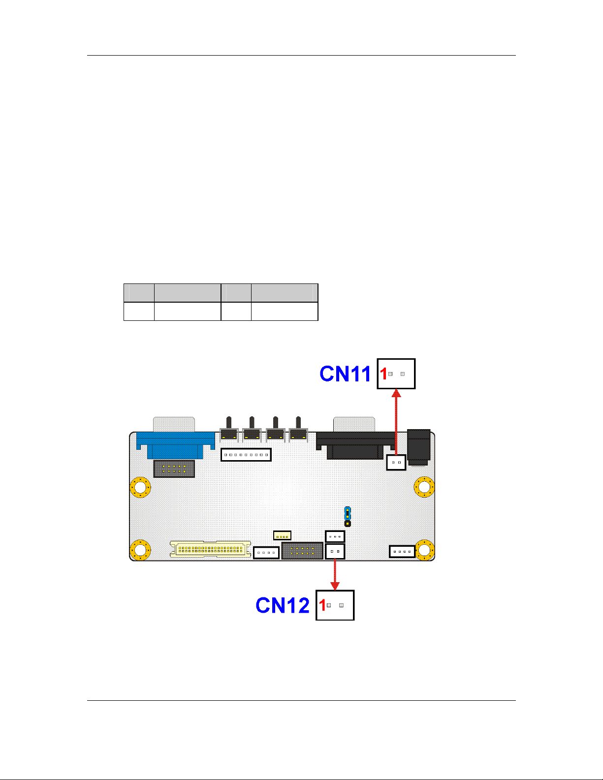
MPD Series CyberResearch® Industrial Monitors
4.2.8 5V Power Connector
CN Label: CN11, CN12
CN Type: 2-pin header
CN Pinouts: See Table 4-4
CN Location: See Figure 4-3
The 5V power connector is a general-purpose power connector.
Pin Description Pin Description
1 +5V 2 GND
Table 4-4: 5V Power Connector Pinouts
Figure 4-3: 5V Power Connector Location
56 ©Copyright 2008 CyberResearch, Inc.
Page 81
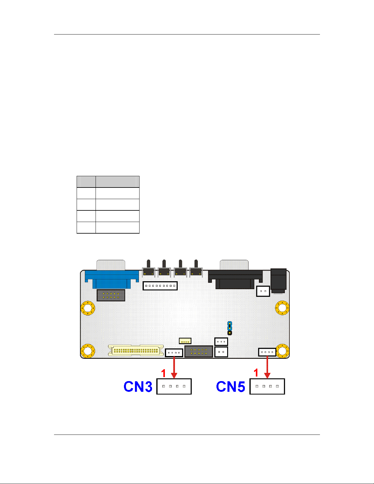
CyberResearch® Industrial Monitors MPD Series
4.2.9 Debugged Port Connector
CN Label: CN3, CN5
CN Type: 4-pin header
CN Pinouts: See Table 4-5
CN Location: See Figure 4-4
Use the debugged port connector to update the LCD Controller BIOS.
Pin Description
1 +5V
2 TX
3 RX
4 GND
Table 4-5: Debugged Port Connector Pinouts
Figure 4-4: Debugged Port Connector Location
CyberResearch, Inc. 57
25 Business Park Drive P: (203) 643-5000; F: (203) 643-5001
Branford, CT USA www.cyberresearch.com
Page 82

MPD Series CyberResearch® Industrial Monitors
4.2.11 Serial Communications Connector
CN Label: COM1
CN Type: 10-pin header
CN Pinouts: See Table 4-7
CN Location: See Figure 4-6
The 9350 LCD Controller has a 10-pin serial communications connector.
Pin Description Pin Description
1 DCD 6 CTS
2 DSR 7 DTR
3 RXD 8 RI
4 RTS 9 GND
5 TXD 10 GND
Table 4-7: Serial Communications Connector Pinouts
Figure 4-6: Serial Communications Connector Location
58 ©Copyright 2008 CyberResearch, Inc.
Page 83
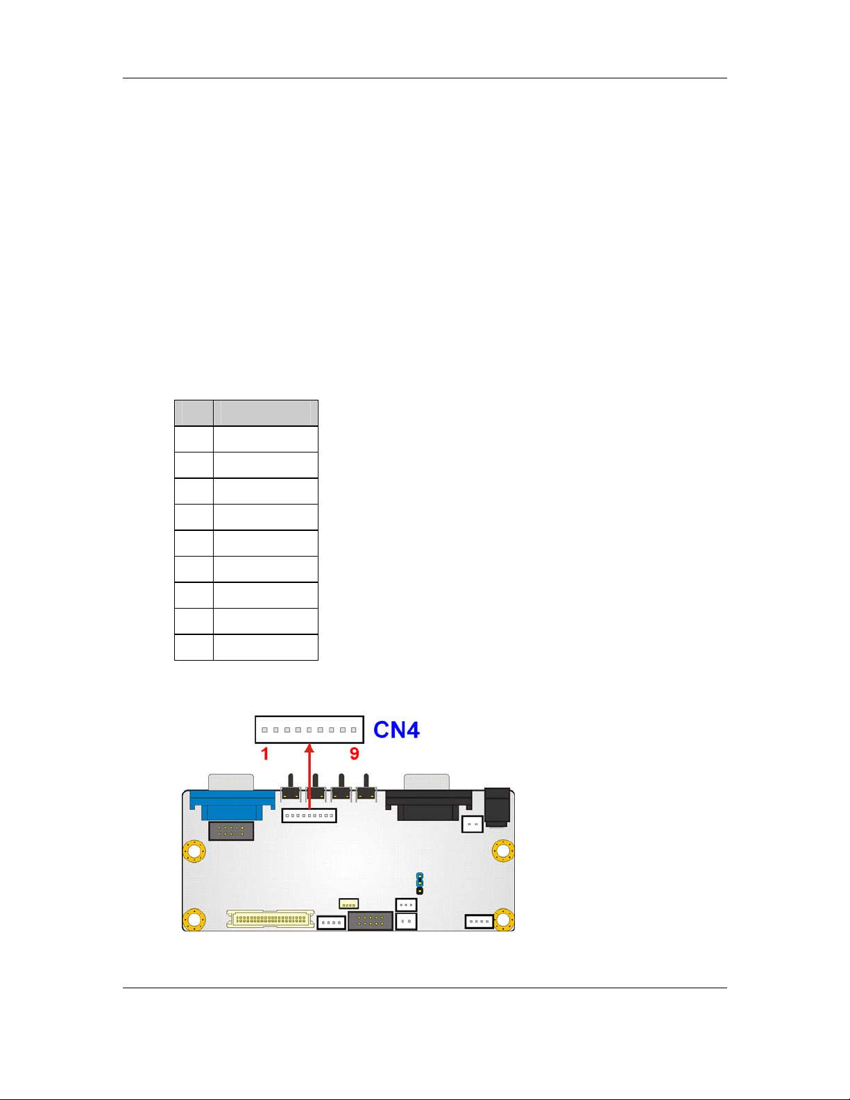
CyberResearch® Industrial Monitors MPD Series
4.2.10 External OSD and LED Indication Connector
CN Label: CN4
CN Type: 9-pin header
CN Pinouts: See Table 4-6
CN Location: See Figure 4-5
The External OSD and LED Indication connector connects to an external OSD controller.
Pin Description
1 LED_ORANGE
2 +5V
3 LED_GREEN
4 MENU/ENTER
5 RIGHT
6 LEFT
7 AUTO
8 LCD ON/OFF
9 GND
Table 4-6: External OSD and LED Indication Connector Pinouts
Figure 4-5: External OSD and LED Indication Connector Location
CyberResearch, Inc. 59
25 Business Park Drive P: (203) 643-5000; F: (203) 643-5001
Branford, CT USA www.cyberresearch.com
Page 84
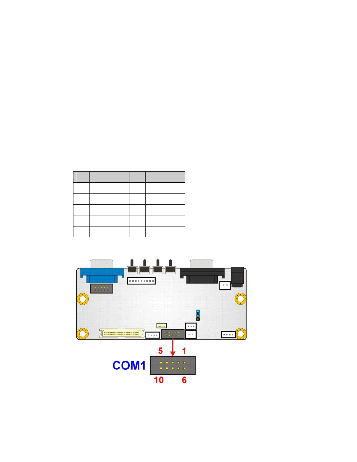
MPD Series CyberResearch® Industrial Monitors
4.2.11 Serial Communications Connector
CN Label: COM1
CN Type: 10-pin header
CN Pinouts: See Table 4-7
CN Location: See Figure 4-6
The 9350 LCD Controller has a 10-pin serial communications connector.
Pin Description Pin Description
1 DCD 6 CTS
2 DSR 7 DTR
3 RXD 8 RI
4 RTS 9 GND
5 TXD 10 GND
Table 4-7: Serial Communications Connector Pinouts
Figure 4-6: Serial Communications Connector Location
60 ©Copyright 2008 CyberResearch, Inc.
Page 85
CyberResearch® Industrial Monitors MPD Series
4.2.12 TTL Output Connector
CN Label: CN7
CN Type: 40-pin header
CN Pinouts: See Table 4-8
CN Location: See Figure 4-7
The TTL output connector connects the LCD panel to the system.
Pin Description Pin Description
2 LCD5V 1 LCD5V
4 GROUND 3 GROUND
6 LCD3V 5 LCD3V
8 GROUND 7 N/C
10 B1 9 B0
12 B3 11 B2
14 B5 13 B4
16 B7 15 B6
18 G1 17 G0
20 G3 19 G2
22 G5 21 G4
24 G7 23 G6
26 R1 25 R0
28 R3 27 R2
30 R5 29 R4
32 R7 31 R6
34 GROUND 33 GROUND
36 FPVS 35 FPCLK
38 FPHS 37 FPDEN
40 ENVEE 39 N/C
Table 4-8: TTL Output Connector Pinouts
CyberResearch, Inc. 61
25 Business Park Drive P: (203) 643-5000; F: (203) 643-5001
Branford, CT USA www.cyberresearch.com
Page 86
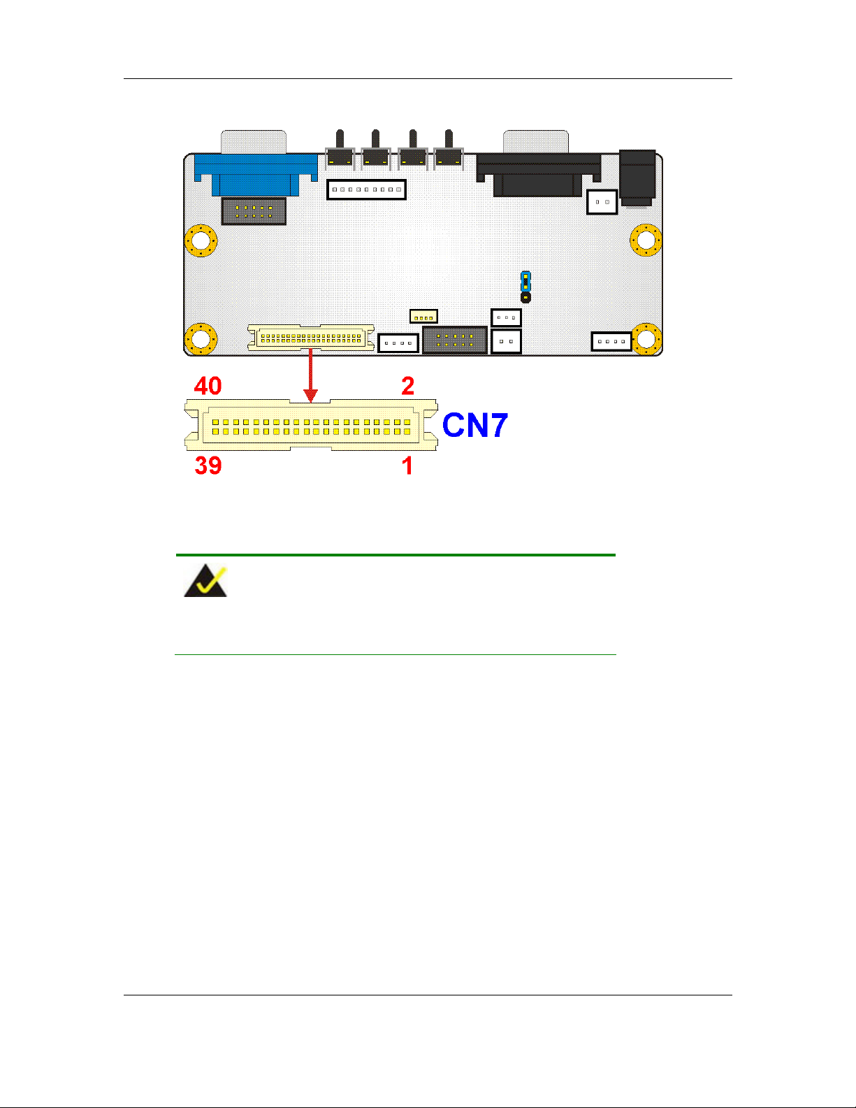
MPD Series CyberResearch® Industrial Monitors
Figure 4-7: TTL Output Connector Location
NOTE:
The supply voltage (3.3V and 5V) can be selected via JP5.
62 ©Copyright 2008 CyberResearch, Inc.
Page 87

CyberResearch® Industrial Monitors MPD Series
4.2.13 VGA Connector
CN Label: CN2
CN Type: 10-pin header
CN Pinouts: See Table 4-9
CN Location: See Figure 4-8
In addition to the standard DB-15 female VGA connector (CN1), a VGA connection can
also be made through the onboard CN2 10-pin header.
Pin Description Pin Description
1 RED 2 DDCCLK
3 GREEN 4 DDCDAT
5 BLUE 6 GROUND
7 HSYNC 8 GROUND
9 VSYNC 10 GROUND
Table 4-9: VGA Connector Pinouts
CyberResearch, Inc. 63
25 Business Park Drive P: (203) 643-5000; F: (203) 643-5001
Branford, CT USA www.cyberresearch.com
Page 88

MPD Series CyberResearch® Industrial Monitors
Figure 4-8: VGA Connector Location
4.2.14 9350 External (Rear Panel) Connectors
Figure 4-9 shows the 9350 external (rear panel) connectors. The peripheral connectors
on the back panel of the monitor can connect to external devices. The peripheral
connectors on the rear panel are:
1 x DC 12V connector
1 x Serial Communications connector
4 x OSD Function Button
1 x VGA conector
Figure 4-9: 9350 External (Rear Panel) Connectors
4.2.15 DC 12V Connector
CN Label: J2
CN Type: DC 12V Jack
CN Pinouts:
CN Location: See Figure 4-9
Use the DC 12V connector to power the monitor.
PIN DESCRIPTION
1 GND
See Table 4-10
2 GND
64 ©Copyright 2008 CyberResearch, Inc.
Page 89
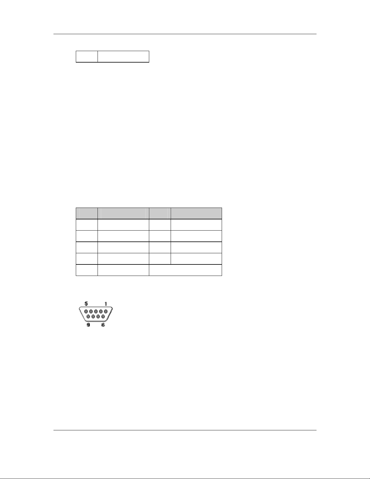
CyberResearch® Industrial Monitors MPD Series
3 DC 12V
Table 4-10: DC 12V Connector Pinouts
4.2.16 RS232 Serial Connector
CN Label: J1
CN Type: D-Sub 9 female connector
CN Pinouts: See Table 4-11 and Figure 4-10
CN Location: See Figure 4-9
Use the RS-232 serial connector to connect the touch panel.
PIN DESCRIPTION PIN DESCRIPTION
1 DCD 6 DSR
2 RXD 7 RTS
3 TXD 8 CTS
4 DTR 9 RI/Vout
5 GND
Table 4-11: RS232 Serial Connector Pinouts
Figure 4-10: RS232 Serial Connector Pinout Locations
CyberResearch, Inc. 65
25 Business Park Drive P: (203) 643-5000; F: (203) 643-5001
Branford, CT USA www.cyberresearch.com
Page 90
MPD Series CyberResearch® Industrial Monitors
4.2.17 OSD Control Buttons
CN Label: JP1, JP2, JP3, JP4
CN Type: Pushbutton
CN Pinouts: See Table 4-12, Table 4-13, Table 4-14, Table 4-15
CN Location: See Figure 4-9
Use these buttons to control the OSD functions. The following tables list each button’s
function and pinouts.
PIN DESCRIPTION PIN DESCRIPTION
1 MENU/SELECT 3 No Connect
2 Ground 4 No Connect
Table 4-12: OSD Control Button JP1 Pinouts
PIN DESCRIPTION PIN DESCRIPTION
1 UP/COLOR ADJUST 3 No Connect
2 Ground 4 No Connect
Table 4-13: OSD Control Button JP2 Pinouts
PIN DESCRIPTION PIN DESCRIPTION
1 DOWN/AUTO ADJUST 3 No Connect
2 Ground 4 No Connect
Table 4-14: OSD Control Button JP3 Pinouts
PIN DESCRIPTION PIN DESCRIPTION
1 LCD ON/OFF 3 No Connect
2 Ground 4 No Connect
Table 4-15: OSD Control Button JP4 Pinouts
66 ©Copyright 2008 CyberResearch, Inc.
Page 91
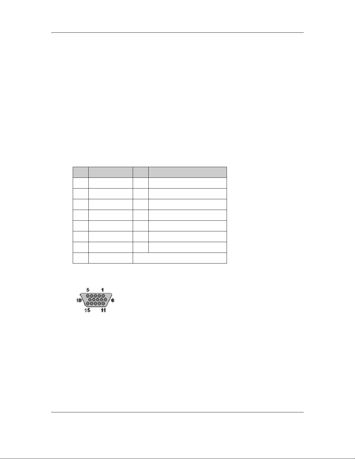
CyberResearch® Industrial Monitors MPD Series
4.2.18 VGA Connector
CN Label: CN1
CN Type: HD-D-sub 15 female connector
CN Pinouts: See Table 4-16 and Figure 4-11
CN Location:
See Figure 4-9
Use the standard HD-D-sub 15-pin VGA connector to connect the monitor to a system.
PIN DESCRIPTION PIN DESCRIPTION
1 Red 9 No Connect
2 Green 10 Ground
3 Blue 11 No Connect
4 No Connect 12 DDC DAT
5 Ground 13 Horizontal Synchronization
6 Ground 14 Vertical Synchronization
7 Ground 15 DDC Clock
8 Ground
Table 4-16: VGA Connector Pinouts
Figure 4-11: VGA Connector Pinout Locations
CyberResearch, Inc. 67
25 Business Park Drive P: (203) 643-5000; F: (203) 643-5001
Branford, CT USA www.cyberresearch.com
Page 92

MPD Series CyberResearch® Industrial Monitors
p
4.2.19 9350 Onboard Jumper
NOTE:
A jumper is a metal bridge used to close an
electrical circuit. It consists of two or three metal
ins and a small metal clip (often protected by a
plastic cover) that slides over the pins to
connect them. To CLOSE/SHORT a jumper
means connecting the pins of the jumper with
the plastic clip and to OPEN a jumper means
removing the plastic clip from a jumper.
The 9350 has one onboard jumper (Table 4-3).
Figure 4-12: Jumpers
Figure 4-13: Jumper Location
68 ©Copyright 2008 CyberResearch, Inc.
Page 93

CyberResearch® Industrial Monitors MPD Series
4.2.20 LCD Panel (TTL) Voltage Select Jumper
Jumper Label: JP5
Jumper Type: 3-pin header
Jumper Location: See Figure 4-13
Jumper Settings: See Table 4-17
The JP5 jumper sets the voltage to the LCD panel.
JP5 Description
1-2 Panel Voltage select 5V
Panel Voltage select 3.3V
2-3
(Default)
Table 4-17: LCD Panel (TTL) Voltage Select Jumper Settings
CyberResearch, Inc. 69
25 Business Park Drive P: (203) 643-5000; F: (203) 643-5001
Branford, CT USA www.cyberresearch.com
Page 94
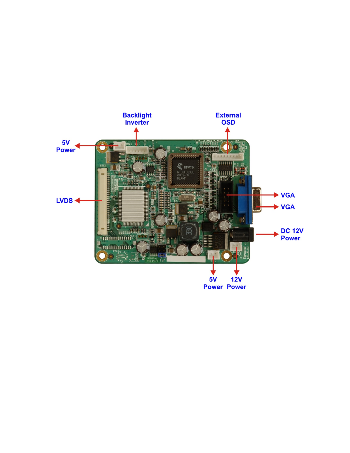
MPD Series CyberResearch® Industrial Monitors
4.3 5350 LCD Controller
The following sections describe the 5350 LCD Controller in detail.
4.3.1 5350 LCD Controller Overview
Figure 4-14: 5350 LCD Controller Overview
4.3.2 5350 LCD Controller Connectors
The 5350 LCD Controller has the following connectors onboard:
1 x VGA connector
1 x External OSD and LED Indication connector
1 x LVDS connector
2 x 5V power connector
1 x 12V power connector
70 ©Copyright 2008 CyberResearch, Inc.
Page 95

CyberResearch® Industrial Monitors MPD Series
1 x Backlight Inverter connector
The 5350 LCD Controller has the following connectors on the board rear panel:
1 x VGA connector
1 x 12V DC power connector
The locations of the peripheral interface connectors for the 5350 LCD Controller are
shown in Section 4.3.3. A complete list of all the peripheral interface connectors can be
seen in Section 4.3.4.
4.3.3 5350 LCD Controller Layout
Figure 4-15 shows the onboard peripheral connectors and onboard jumpers.
Figure 4-15: Connector and Jumper Locations
CyberResearch, Inc. 71
25 Business Park Drive P: (203) 643-5000; F: (203) 643-5001
Branford, CT USA www.cyberresearch.com
Page 96

MPD Series CyberResearch® Industrial Monitors
4.3.4 5350 Peripheral Interface Connectors
Table 4-18 shows a list of the peripheral interface connectors on the 5350 LCD
Controller. Detailed descriptions of these connectors can be found in Section 4.3.7.
Connector Type Label
5V Power connector 2-pin header CN8, CN9
12V Power connector 2-pin header CN7
Backlight Inverter connector 6-pin header CN6
External OSD and
LED Indication connector
LVDS Output connector 30-pin header CN5
VGA connector 10-pin header J2
Table 4-18: 5350 Peripheral Interface Connectors
9-pin header CN2
4.3.5 5350 Rear Panel Connectors
Table 4-19 lists the rear panel connectors and jumpers on the 5350 LCD Controller.
Detailed descriptions of these connectors and jumpers can be found in Section 4.3.14.
Connector Type Label
DC 12V Power connector DC Power Jack J3
VGA Connector 15-pin VGA connector J1
Table 4-19: 5350 Rear Panel Connectors
4.3.6 5350 Onboard Jumper
Table 4-20 lists the onboard jumper. A detailed description of the jumper can be found in
Section 4.3.17.
Jumper Type Label
LCD Panel Voltage Select 3-pin header JP1
Table 4-20: 5350 Onboard Jumper
72 ©Copyright 2008 CyberResearch, Inc.
Page 97
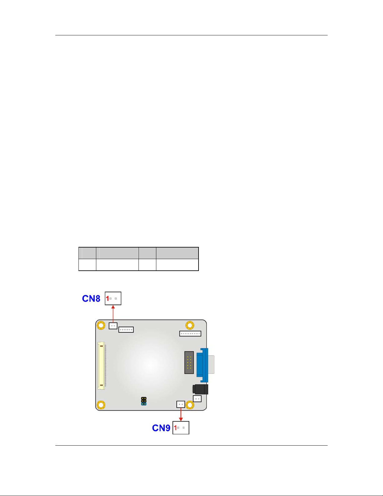
CyberResearch® Industrial Monitors MPD Series
4.3.7 5350 Internal Peripheral Connectors
Internal peripheral connectors on the 5350 LCD Controller are only accessible when the
board is outside of the monitor. This section has complete descriptions of all the internal,
peripheral connectors on the 5350 LCD Controller.
4.3.8 5V Power Connector
CN Label: CN8, CN9
CN Type: 2-pin header
CN Pinouts: See Table 4-21
CN Location: See Figure 4-16
The 5V power connector is a general-purpose power connector.
Pin Description Pin Description
1 +5V 2 GND
Table 4-21: 5V Power Connector Pinouts
CyberResearch, Inc. 73
25 Business Park Drive P: (203) 643-5000; F: (203) 643-5001
Branford, CT USA www.cyberresearch.com
Page 98
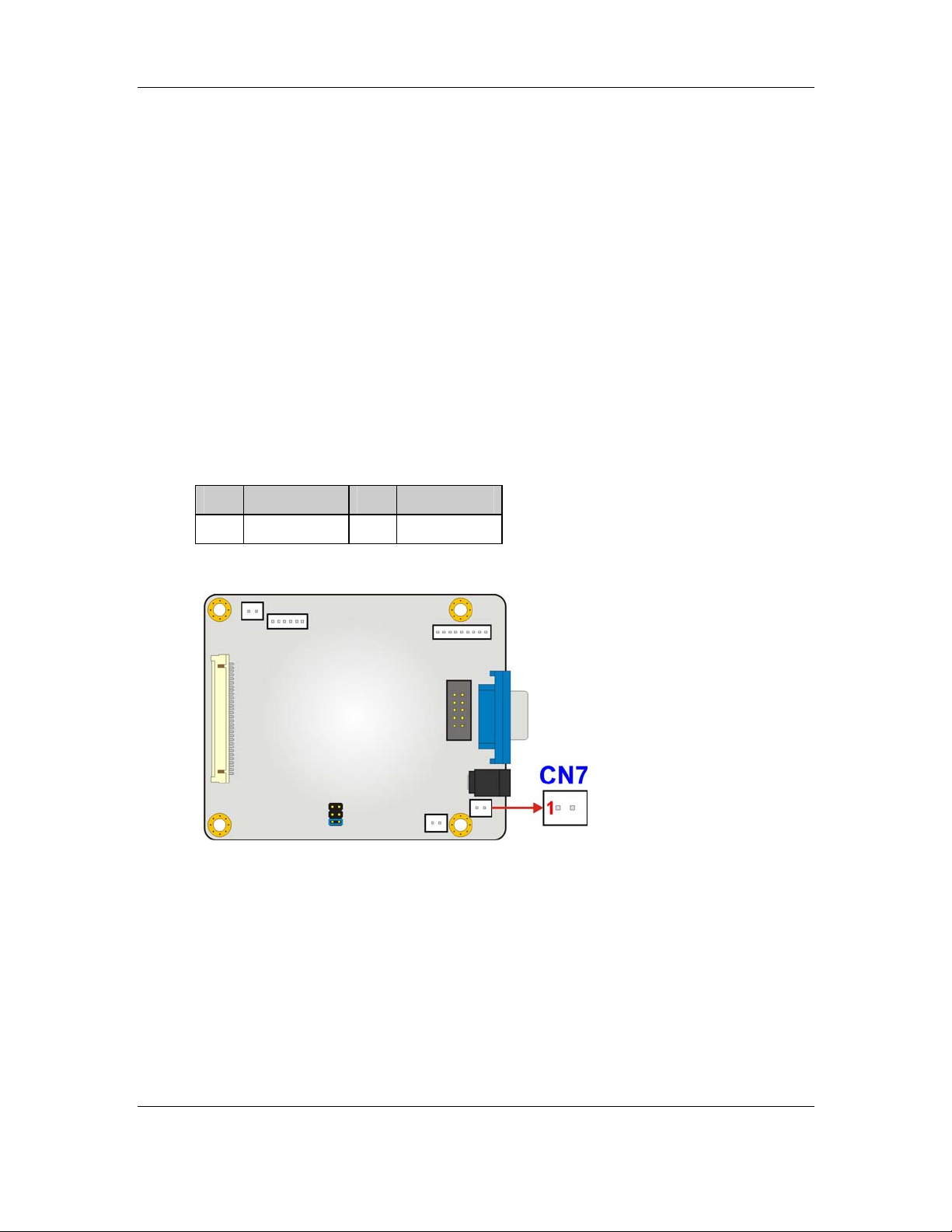
MPD Series CyberResearch® Industrial Monitors
Figure 4-16: 5V Power Connector Location
4.3.9 12V Power Connector
CN Label: CN7
CN Type: 2-pin header
CN Pinouts: See Table 4-22
CN Location: See Figure 4-17
The 12V power connector is a general-purpose power connector.
Pin Description Pin Description
1 +12V 2 GND
Table 4-22: 12V Power Connector Pinouts
Figure 4-17: 12V Power Connector Location
4.3.10 Backlight Inverter Connector
CN Label: CN6
CN Type: 6-pin header
CN Pinouts: See Table 4-23
CN Location: See Figure 4-18
The Inverter connector connects to the LCD backlight.
74 ©Copyright 2008 CyberResearch, Inc.
Page 99
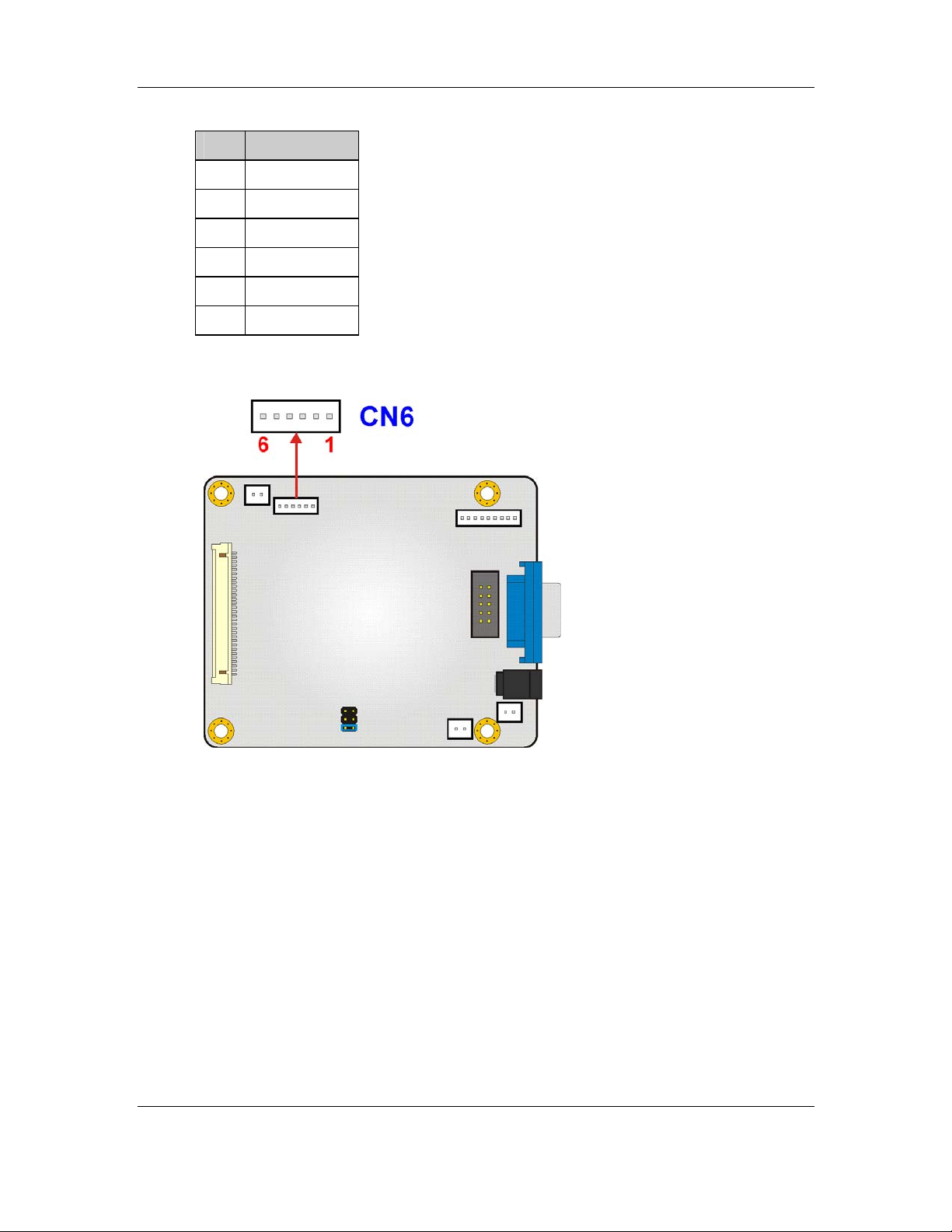
CyberResearch® Industrial Monitors MPD Series
Pin Description
1 +12V
2 +12V
3 On/Off
4 BKLT_ADJ
5 GND
6 GND
Table 4-23: Backlight Inverter Connector Pinouts
Figure 4-18: Backlight Inverter Connector Location
4.3.11 External OSD and LED Indication Connector
CN Label: CN2
CN Type: 9-pin header
CN Pinouts: See Table 4-24
CN Location: See Figure 4-19
CyberResearch, Inc. 75
25 Business Park Drive P: (203) 643-5000; F: (203) 643-5001
Branford, CT USA www.cyberresearch.com
Page 100
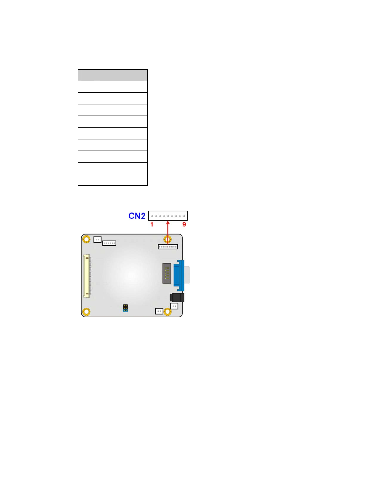
MPD Series CyberResearch® Industrial Monitors
The External OSD and LED Indication connector connects to an external OSD controller.
Pin Description
1 LED_ORANGE
2 +5V
3 LED_GREEN
4 MENU/ENTER
5 RIGHT
6 LEFT
7 AUTO
8 LCD ON/OFF
9 GND
Table 4-24: External OSD and LED Indication Connector Pinouts
Figure 4-19: External OSD and LED Indication Connector Location
4.3.12 LVDS Output Connector
CN Label: CN5
CN Type: 30-pin header
CN Pinouts: See Table 4-25
76 ©Copyright 2008 CyberResearch, Inc.
 Loading...