

Page 1

Motherboards
MICA Series
Mini-ITX Motherboard with VGA,
Dual Gigabit LAN, DIO, Audio
MICA C2-24-X: 2.4GHz Core 2 Duo Processor
MICA PD-32-X
MICA PD-36-X: 3.6GHz Pentium D Processor
: 3.2GHz Pentium D Processor
®
USER’S MANUAL
VER. 1.0 • SEP 2006
No part of this manual may be reproduced without permission
CyberResearch®,Inc.
www.cyberresearch.com
25 Business Park Dr., Branford, CT 06405 USA
203-483-8815 (9am to 5pm EST) FAX: 203-483-9024
Page 2

Page 3

Page 4

Page 5

CyberResearch® CPU Cards MICA Series
©Copyright 2006
All Rights Reserved.
September 1, 2006
The information in this document is subject to change without prior notice
in order to improve reliability, design, and function and does not represent
a commitment on the part of CyberResearch, Inc.
In no event will CyberResearch, Inc. be liable for direct, indirect, special,
incidental, or consequential damages arising out of the use of or inability
to use the product or documentation, even if advised of the possibility of
such damages.
This document contains proprietary information protected by copyright.
All rights are reserved. No part of this manual may be reproduced by any
mechanical, electronic, or other means in any form without prior written
permission of CyberResearch, Inc.
Trademarks
“CyberResearch,” and “MICA Series,” are trademarks of CyberResearch,
Inc. Other product names mentioned herein are used for identification
purposes only and may be trademarks and/or registered trademarks of
their respective companies.
• NOTICE •
CyberResearch, Inc. does not authorize any CyberResearch product for
use in life support systems, medical equipment, and/or medical devices
without the written approval of the President of CyberResearch, Inc. Life
support devices and systems are devices or systems which are intended
for surgical implantation into the body, or to support or sustain life and
whose failure to perform can be reasonably expected to result in injury.
Other medical equipment includes devices used for monitoring, data
acquisition, modification, or notification purposes in relation to life
support, life sustaining, or vital statistic recording. CyberResearch
products are not designed with the components required, are not subject
to the testing required, and are not submitted to the certification required
to ensure a level of reliability appropriate for the treatment and diagnosis of
humans.
CyberResearch, Inc. iii
25 Business Park Drive P: (203) 483-8815; F: (203) 483-9024
Branford, CT USA www.cyberresearch.co m
Page 6

MICA Series CyberResearch® CPU Cards
Intentionally Blank
iv ©Copyright 2006 CyberResearch, Inc.
Page 7

CyberResearch® Motherboards MICA Series
CyberResearch, Inc. 1
25 Business Park Drive P: (203) 483-8815; F: (203) 483-9024
Branford, CT USA www.cyberresearch.com
Page 8

MICA Series CyberResearch® Motherboards
REVISION HISTORY
Title MICA Series Intel Pentium D/Celeron D Motherboard
Revision Number Description Date of Issue
1.0 Initial release September 2006
2 ©Copyright 2006 CyberResearch, Inc.
Page 9

CyberResearch® Motherboards MICA Series
Table of Contents
1 INTRODUCTION................................................................................................... 15
2 MICA SERIES OVERVIEW................................................................................. 16
2.1.1 MICA Applications........................................................................................... 16
2.1.2 MICA Series Benefits....................................................................................... 16
2.1.3 MICA Series Features...................................................................................... 17
2.2 MICA SERIES BOARD OVERVIEW ............................................................................ 17
2.2.1 MICA Series Connectors.................................................................................. 18
2.2.2 Technical Specifications................................................................................... 19
3 DETAILED SPECIFICATIONS........................................................................... 21
3.1 OVERVIEW................................................................................................................ 22
3.2 DIMENSIONS............................................................................................................. 22
3.2.1 Board Dimensions............................................................................................ 22
3.2.2 External Interface Panel Dimensions.............................................................. 23
3.3 CPU SUPPORT.......................................................................................................... 23
3.3.1 Intel® Pentium® D.......................................................................................... 23
3.3.2 Intel® Pentium® 4........................................................................................... 24
3.3.3 Intel® Celeron® D........................................................................................... 24
ON-BOARD CHIPSET................................................................................................. 24
3.4
3.4.1 Intel® 945G Express Chipset........................................................................... 24
3.4.2 Intel® 82945G Graphics and Memory Controller Hub .................................. 25
3.4.3 Intel® ICH7 I/O Controller Hub..................................................................... 25
3.5 GRAPHICS SUPPORT.................................................................................................. 26
3.6 MEMORY SUPPORT ................................................................................................... 26
3.7 PCI BUS INTERFACE SUPPORT.................................................................................. 26
3.8 GBE ETHERNET........................................................................................................ 26
3.9 DRIVE INTERFACES .................................................................................................. 27
3.9.1 SATA Drives..................................................................................................... 27
3.9.2 IDE Interfaces.................................................................................................. 27
3.10 SERIAL PORTS ........................................................................................................ 28
CyberResearch, Inc. 3
25 Business Park Drive P: (203) 483-8815; F: (203) 483-9024
Branford, CT USA www.cyberresearch.com
Page 10

MICA Series CyberResearch® Motherboards
3.11 REAL TIME CLOCK ................................................................................................. 28
3.12 INFRARED DATA ASSOCIATION (IRDA) INTERFACE ................................................ 28
3.13 USB INTERFACES................................................................................................... 28
3.14 BIOS...................................................................................................................... 28
3.15 OPERATING TEMPERA TURE AND TEMPERATURE CONTROL..................................... 28
3.16 AUDIO CODEC........................................................................................................ 29
3.17 POWER CONSUMPTION........................................................................................... 30
3.18 PACKAGED CONTENTS AND OPTIONAL ACCESSORY ITEMS..................................... 30
3.18.1 Package Contents........................................................................................... 30
3.18.2 Optional Accessory Items............................................................................... 31
4 CONNECTORS AND JUMPERS ......................................................................... 33
4.1 PERIPHERAL INTERFACE CONNECTORS..................................................................... 34
4.1.1 MICA Series Layout......................................................................................... 34
4.1.2 Peripheral Interface Connectors ..................................................................... 35
4.1.3 Rear Panel Connectors.................................................................................... 36
4.1.4 On-board Jumpers........................................................................................... 36
4.2 INTERNAL PERIPHERAL CONNECTORS...................................................................... 37
4.2.1 ATX + CPU 12V Power Connector................................................................. 37
4.2.2 Fan Connectors................................................................................................ 38
4.2.3 Front Panel Connector.................................................................................... 39
4.2.4 Digital Input/Output Connector....................................................................... 40
4.2.5 IDE Connector................................................................................................. 41
4.2.6 IR Interface Connector .................................................................................... 43
4.2.7 Mini PCI Slot ................................................................................................... 44
4.2.8 PCI Express x16 Slot........................................................................................ 46
4.2.9 ATX Power Connector ..................................................................................... 49
4.2.10 Serial Port Connector.................................................................................... 50
4.2.11 SATA Drive Connectors.................................................................................. 51
4.2.12 TPM Connector.............................................................................................. 52
4.2.13 Internal USB Connectors............................................................................... 54
EXTERNAL INTERFACE CONNECTORS ....................................................................... 55
4.3
4.3.1 Audio Connectors............................................................................................. 55
4.3.2 CRT Connector ................................................................................................ 56
4.3.3 Ethernet Connectors ........................................................................................ 57
4.3.4 Keyboard/Mouse Connector............................................................................ 58
4 ©Copyright 2006 CyberResearch, Inc.
Page 11

CyberResearch® Motherboards MICA Series
4.3.5 Serial Port Connectors .................................................................................... 59
4.3.6 USB Connectors............................................................................................... 60
5 INST ALLA TION AND CONFIGURA TION ....................................................... 63
5.1
ANTI-STATIC PRECAUTIONS...................................................................................... 64
5.2 INSTALLATION CONSIDERATIONS.............................................................................. 64
5.2.1 Installation Notices.......................................................................................... 64
5.3 UNPACKING.............................................................................................................. 65
5.3.1 Unpacking Precautions.................................................................................... 65
5.3.2 Checklist........................................................................................................... 66
5.4 MICA SERIES MOTHERBOARD INSTALLATION.......................................................... 66
5.5 SOCKET LGA775 CPU INSTALLATION..................................................................... 67
5.5.1 CPU Selection: HT Functionality Requirements............................................. 67
5.5.1.1 CPU Installation........................................................................................ 67
5.5.2 Socket LGA775 Cooling Kit Installation ......................................................... 70
5.5.3 DIMM Module Installation.............................................................................. 73
5.5.3.1 Purchasing the Memory Module............................................................... 73
5.5.3.2 DIMM Module Installation....................................................................... 73
5.5.4 Peripheral Device Connection......................................................................... 74
5.5.4.1 IDE Disk Drive Connector (IDE1) ........................................................... 75
5.5.4.2 COM Port Connectors............................................................................... 76
5.6 ON-BOARD JUMPERS ................................................................................................ 76
5.6.1 Clear CMOS Jumper........................................................................................ 77
5.6.2 COM2 Mode Selection..................................................................................... 78
5.7 CHASSIS INSTALLATION............................................................................................ 79
5.8 REAR PANEL CONNECTORS ...................................................................................... 79
5.8.1 LCD Panel Connection.................................................................................... 79
5.8.2 Ethernet Connection ........................................................................................ 79
5.8.3 USB Connection............................................................................................... 79
5.8.4 Serial Connection............................................................................................. 79
5.8.5 Keyboard and Mouse Connection.................................................................... 79
5.8.6 Audio Interface................................................................................................. 80
6 AMI BIOS SETUP.................................................................................................. 82
6.1 INTRODUCTION......................................................................................................... 83
6.1.1 Starting Setup................................................................................................... 83
CyberResearch, Inc. 5
25 Business Park Drive P: (203) 483-8815; F: (203) 483-9024
Branford, CT USA www.cyberresearch.com
Page 12

MICA Series CyberResearch® Motherboards
6.1.2 Using Setup...................................................................................................... 83
6.1.3 Getting Help..................................................................................................... 84
6.1.4 Unable to Reboot after Configuration Changes.............................................. 84
6.1.5 BIOS Menu Bar................................................................................................ 84
6.2 MAIN........................................................................................................................ 84
6.3 ADVANCED............................................................................................................... 86
6.3.1 CPU Configuration.......................................................................................... 87
6.3.2 IDE Configuration........................................................................................... 88
6.3.2.1 IDE Master, IDE Slave............................................................................. 91
6.3.3 Super IO Configuration ................................................................................... 95
6.3.4 Hardware Health Configuration...................................................................... 98
6.3.5 ACPI Configuration....................................................................................... 101
6.3.5.1 General ACPI Configuration...................................................................102
6.3.6 APM Configuration........................................................................................ 103
6.3.7 MPS Configuration........................................................................................ 106
6.3.8 Smbios Configuration .................................................................................... 107
6.3.9 Remote Access Configuration........................................................................ 108
6.3.10 USB Configuration........................................................................................112
6.3.10.1 USB Mass Storage Device Configuration..............................................115
6.4 BOOT.......................................................................................................................116
6.4.1 Boot Settings Configuration............................................................................116
6.4.2 Boot Device Priority.......................................................................................119
6.4.3 Hard Disk Drives........................................................................................... 120
6.4.4 Removable Drives.......................................................................................... 121
6.4.5 CD/DVD Drives............................................................................................. 122
6.5 SECURITY............................................................................................................... 123
CHIPSET ................................................................................................................. 124
6.6
6.6.1 North Bridge Configuration........................................................................... 125
6.7 EXIT....................................................................................................................... 128
7 SOFTWARE DRIVERS....................................................................................... 131
7.1 AVAILABLE SOFTWARE DRIVERS ............................................................................ 132
7.2
CHIPSET DRIVER INSTALLATION............................................................................. 132
7.3 VGA DRIVER ......................................................................................................... 135
7.4 BROADCOM LAN DRIVER (FOR GBE LAN) INSTALLATION ................................... 139
7.5 REALTEK AUDIO DRIVER (ALC655) INSTALLATION .............................................. 143
6 ©Copyright 2006 CyberResearch, Inc.
Page 13

CyberResearch® Motherboards MICA Series
7.6
INTEL MATRIX STORAGE MANAGER INSTALLATION ............................................... 146
A BIOS CONFIGURATION OPTIONS ................................................................ 149
A.1 BIOS CONFIGURATION OPTIONS ........................................................................... 150
B WATCHDOG TIMER .......................................................................................... 155
C ADDRESS MAPPING.......................................................................................... 159
C.1 IO ADDRESS MAP.................................................................................................. 160
C.2 1ST MB MEMORY ADDRESS MAP.......................................................................... 160
C.3 IRQ MAPPING TABLE ............................................................................................ 161
C.4 DMA CHANNEL ASSIGNMENTS ............................................................................. 161
D EXTERNAL AC’97 AUDIO CODEC .................................................................163
D.1 INTRODUCTION...................................................................................................... 164
D.1.1 Accessing the AC’97 CODEC....................................................................... 164
D.1.2 Driver Installation......................................................................................... 164
D.2 SOUND EFFECT CONFIGURATION........................................................................... 165
D.2.1 Accessing the Sound Effects Manager.......................................................... 165
D.2.2 Sound Effect Manager Configuration Options ............................................. 166
E INDEX.................................................................................................................... 169
CyberResearch, Inc. 7
25 Business Park Drive P: (203) 483-8815; F: (203) 483-9024
Branford, CT USA www.cyberresearch.com
Page 14

MICA Series CyberResearch® Motherboards
List of Figures
Figure 1-1: MICA Series Board Overview .................................................................17
Figure 2-1: MICA Series Dimensions (mm) ..............................................................23
Figure 2-2: External Interface Panel Dimensions (mm)...........................................23
Figure 3-1: Connector and Jumper Locations.........................................................34
Figure 3-2: CPU 12V Power Connector Location.....................................................37
Figure 3-3: Fan Connector Locations .......................................................................38
Figure 3-4: Front Panel Connector Location............................................................40
Figure 3-5: Digital I/O Connector Location...............................................................41
Figure 3-6: IDE Device Connector Location.............................................................42
Figure 3-7: IR Connector Location............................................................................44
Figure 3-8: Mini PCI Slot Location.............................................................................45
Figure 3-9: PCI Express x16 Slot Location...............................................................47
Figure 3-10: Power Connector Location...................................................................49
Figure 3-11: Serial Port Connector Location............................................................51
Figure 3-12: SATA Drive Connector Locations........................................................52
Figure 3-13: TPM Connector Location......................................................................53
Figure 3-14: Internal USB Connector Locations......................................................54
Figure 3-15: MICA Series External Interface Connectors.......................................55
Figure 3-16: Audio Connector....................................................................................56
Figure 3-17: VGA Connector......................................................................................57
Figure 3-18: RJ-45 Ethernet Connector ....................................................................58
Figure 3-19: PS/2 Pinouts...........................................................................................59
Figure 3-20: External Serial Port Connector ............................................................60
Figure 4-1: Intel LGA775 Socket................................................................................68
Figure 4-2: Remove the CPU Socket Protective Shield...........................................69
Figure 4-3: Open the CPU Socket Load Plate ..........................................................69
Figure 4-4: Insert the Socket LGA775 CPU ..............................................................70
Figure 4-5: CyberResearch LGA-775 Cooling Kit....................................................71
8 ©Copyright 2006 CyberResearch, Inc.
Page 15

CyberResearch® Motherboards MICA Series
Figure 4-6: Securing the Heat sink to the PCB Board.............................................72
Figure 4-7: Installing the DIMM Module ....................................................................74
Figure 4-8: Locking the DIMM Module ......................................................................74
Figure 4-9: Connection of IDE Connector ................................................................75
Figure 4-10 Jumper.....................................................................................................76
Figure 4-11: Jumper Locations..................................................................................77
Figure 6-1: InstallShield Wizard Preparation Screen............................................ 133
Figure 6-2: Welcome Screen................................................................................... 133
Figure 6-3: License Agreement............................................................................... 134
Figure 6-4: Readme Information............................................................................. 134
Figure 6-5: Restart the Computer........................................................................... 135
Figure 6-6: Starting Install Shield Wizard Screen................................................. 136
Figure 6-7: Preparing Setup Screen....................................................................... 136
Figure 6-8: VGA Driver Installation Welcome Screen........................................... 137
Figure 6-9: VGA Driver License Agreement.......................................................... 137
Figure 6-10: VGA Driver Installing Notice.............................................................. 138
Figure 6-11: VGA Driver Installation Complete..................................................... 138
Figure 6-12: Access Windows Control Panel........................................................ 139
Figure 6-13: Double Click the System Icon ........................................................... 140
Figure 6-14: Double Click the Device Manager Tab.............................................. 140
Figure 6-15: Device Manager List........................................................................... 141
Figure 6-16: Search for Suitable Driver.................................................................. 141
Figure 6-17: Locate Driver Files.............................................................................. 142
Figure 6-18: Location Browsing Window............................................................... 143
Figure 6-19: InstallShield Wizard Extracting Files................................................ 143
Figure 6-20: Audio Driver Install Shield Wizard Starting ..................................... 144
Figure 6-21: Audio Driver Setup Preparation........................................................ 144
Figure 6-22: Audio Driver Digital Signal ................................................................ 145
Figure 6-23: Audio Driver Installation Continues ................................................. 145
Figure 6-24: Audio Driver Installation Complete................................................... 146
Figure 6-25: Preparing Setup Screen..................................................................... 147
CyberResearch, Inc. 9
25 Business Park Drive P: (203) 483-8815; F: (203) 483-9024
Branford, CT USA www.cyberresearch.com
Page 16

MICA Series CyberResearch® Motherboards
List of Tables
Table 1-1: Technical Specifications ..........................................................................20
Table-2-1: Supported CPUs........................................................................................23
Table 2-2: Power Consumption .................................................................................30
Table 3-1: Peripheral Interface Connectors..............................................................36
Table 3-2: Rear Panel Connectors.............................................................................36
Table 3-3: On-board Jumpers....................................................................................37
Table 3-4: CPU 12V Power Connector Pinouts........................................................38
Table 3-5: CPU Fan Connector Pinouts....................................................................39
Table 3-6: System Fan Connector Pinouts...............................................................39
Table 3-7: Front Panel Connector Pinouts ...............................................................40
Table 3-8: Digital I/O Connector Pinouts ..................................................................41
Table 3-9: IDE Connector Pinouts.............................................................................43
Table 3-10: IR Connector Pinouts..............................................................................44
Table 3-11: Mini PCI Slot Pinouts..............................................................................46
Table 3-12: PCIe x16 Side A Pinouts.........................................................................48
Table 3-13: PCIe x16 Side B Pinouts.........................................................................49
Table 3-14: Power Connector Pinouts ......................................................................50
Table 3-15: Serial Port Connector Pinouts...............................................................51
Table 3-16: SATA Drive Connector Pinouts.............................................................52
Table 3-17: TPM Connector Pinouts..........................................................................54
Table 3-18: USB1 and USB2 Pinouts.........................................................................55
Table 3-19: VGA Connector Pinouts .........................................................................57
Table 3-20: LAN1 and LAN2 Pinouts.........................................................................58
Table 3-21: RJ-45 Ethernet Connector LEDs............................................................58
Table 3-22: PS/2 Connector Pinouts .........................................................................59
Table 3-23: External Serial Port Pinouts...................................................................60
Table 3-24: External USB Connector Pinouts..........................................................61
Table 4-1: CyberResearch Provided Cables.............................................................75
10 ©Copyright 2006 CyberResearch, Inc.
Page 17

CyberResearch® Motherboards MICA Series
Table 4-2: On-board Jumpers....................................................................................77
Table 4-3: Clear CMOS Jumper Settings ..................................................................78
Table 4-4: JP2 Jumper Settings.................................................................................79
Table 5-1: BIOS Navigation Keys...............................................................................84
CyberResearch, Inc. 11
25 Business Park Drive P: (203) 483-8815; F: (203) 483-9024
Branford, CT USA www.cyberresearch.com
Page 18

MICA Series CyberResearch® Motherboards
List of BIOS Menus
BIOS Menu 1: Main......................................................................................................85
BIOS Menu 2: Advanced.............................................................................................87
BIOS Menu 3: CPU Configuration..............................................................................88
BIOS Menu 4: IDE Configuration ...............................................................................89
BIOS Menu 5: IDE Master and IDE Slave Configuration..........................................91
BIOS Menu 6: Super IO Configuration......................................................................95
BIOS Menu 7: Hardware Health Configuration.........................................................99
BIOS Menu 8: ACPI Configuration.......................................................................... 102
BIOS Menu 9: General ACPI Configuration [Advanced\ ACPI Configuration]... 103
BIOS Menu 10: APM Configuration........................................................................ 104
BIOS Menu 11: MPS Configuration ........................................................................ 107
BIOS Menu 12: Smbios Configuration [Advanced] .............................................. 108
BIOS Menu 13: Remote Access Configuration [Advanced] ................................ 109
BIOS Menu 14: USB Configuration......................................................................... 113
BIOS Menu 15: USB Mass Storage Device Configuration.................................... 115
BIOS Menu 16: Boot................................................................................................. 116
BIOS Menu 17: Boot Settings Configuration......................................................... 117
BIOS Menu 18: Boot Device Priority Settings....................................................... 120
BIOS Menu 19: Removable Drives.......................................................................... 122
BIOS Menu 20: Security........................................................................................... 123
BIOS Menu 21: Chipset............................................................................................ 124
BIOS Menu 22:NorthBridge Chipset Configuration.............................................. 126
BIOS Menu 23:Exit ................................................................................................... 129
12 ©Copyright 2006 CyberResearch, Inc.
Page 19

CyberResearch® Motherboards MICA Series
Glossary
AC ’97 Audio Codec 97
ACPI Advanced Configuration and
Power Interface
APM Advanced Power Management
ARMD ATAPI Removable Media Device
ASKIR Shift Keyed Infrared
ATA Advanced Technology
Attachments
BIOS Basic Input/Output System
CFII Compact Flash Type 2
CMOS Complementary Metal Oxide
Semiconductor
CPU Central Processing Unit
Codec Compressor/Decompressor
COM Serial Port
DAC Digital to Analog Converter
DDR Double Data Rate
HDD Hard Disk Drive
IDE Integrated Data Electronics
I/O Input/Output
ICH4 I/O Controller Hub 4
L1 Cache Level 1 Cache
L2 Cache Level 2 Cache
LCD Liquid Crystal Display
LPT Parallel Port Connector
LVDS Low Voltage Differential Signaling
MAC Media Access Controller
OS Operating System
PCI Peripheral Connect Interface
PIO Programmed Input Output
PnP Plug and Play
POST Power On Self Test
RAM Random Access Memory
SATA Serial ATA
DIMM Dual Inline Memory Module
DIO Digital Input/Output
DMA Direct Memory Access
EIDE Enhanced IDE
EIST Enhanced Int el SpeedStep
Technology
FDD Floppy Disk Drive
FDC Floppy Disk Connector
FFIO Flexible File Input/Output
FIFO First In/First Out
FSB Front Side Bus
IrDA Infrared Data Association
CyberResearch, Inc. 13
25 Business Park Drive P: (203) 483-8815; F: (203) 483-9024
Branford, CT USA www.cyberresearch.com
S.M.A.R.T Self Monitoring Analysis and
Reporting Technology
SPD Serial Presence Detect
S/PDI Sony/Philips Digital Interface
SDRAM Synchronous Dynamic Random
Access Memory
SIR Serial Infrared
UART Universal Asynchronous
Receiver-transmitter
USB Universal Serial Bus
VGA Video Graphics Adapter
Page 20

MICA Series CyberResearch® Motherboards
14 ©Copyright 2006 CyberResearch, Inc.
Page 21

CyberResearch® Motherboards MICA Series
Chapter
1
1 Introduction
CyberResearch, Inc. 15
25 Business Park Drive P: (203) 483-8815; F: (203) 483-9024
Branford, CT USA www.cyberresearch.com
Page 22

MICA Series CyberResearch® Motherboards
2 MICA Series Overview
The Mini-ITX form factor MICA Series with Pentium 4 / Pentium D / Celeron D CPU
platform is fully equipped with latest technology and advanced multi-mode I/Os.
2.1.1 MICA Applications
The MICA is designed for applications in the following areas:
Industrial and hard environment PC applications
Human Machine Interface (HMI) applications
Communication and network monitoring applications
Marine, GPS and transportation applications
Financial, retail and kiosk applications
Medical applications
2.1.2 MICA Series Benefits
Some of the MICA Series benefits include:
Dual-core Intel® processor support
DDR2 memory technology support
o Dual-channel DDR2 memory technology at 667MHz
o Up to 10.7GB/s of peak memory bandwidth
SATA II with 3.0Gb/s transfer rate
Dual PCIe GbE enhance high performance in network
Multiple storage option integration including
40 Pin IFM or 2.5”HDD
o
o Four SATA II ports support
Supports PCI Express x16 high-performance graphic card
o 8-cm low profile
o DVI/VGA/HDTV/LVDS output
Low profile design for embedded chassis
16 ©Copyright 2006 CyberResearch, Inc.
Page 23
CyberResearch® Motherboards MICA Series
2.1.3 MICA Series Features
Some of the MICA Series features are listed below:
Complies with RoHS
Supports Intel® Pentium 4 / Pentium D / Celeron D CPUs
Supports a maximum front side bus (FSB) speed up to 1066MHz
Supports up to 2GB of 400MHz, 533MHz or 667MHz of DDR2 memory
Comes with two high performance gigabit Ethernet (GbE) controller
Supports four SATA channels with transfer rates up to 3.0Gb/s
Supports eight USB 2.0 devices
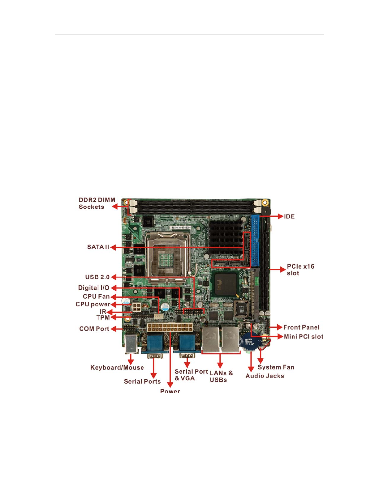
2.2 MICA Series Board Overview
Figure 2-1: MICA Series Board Overview
CyberResearch, Inc. 17
25 Business Park Drive P: (203) 483-8815; F: (203) 483-9024
Branford, CT USA www.cyberresearch.com
Page 24

MICA Series CyberResearch® Motherboards
2.2.1 MICA Series Connectors
The MICA Series has the following connectors on-board:
1 x CPU 12V power connector
2 x DDR2 DIMM sockets
2 x Fan connectors
1 x Front panel connector
1 x Digital Input/Output connector
1 x IDE Interface connector
1 x IR interface connector
1 x Mini PCI slot
1 x PCI Express x16 slot
1 x Power connector
1 x Serial port connector
4 x SATA II connectors
1 x TPM connector
2 x USB connectors
The MICA Series has the following connectors on the board rear panel:
2 x Audio jacks
1 x CRT connector
2 x Ethernet connectors
2 x Keyboard/Mouse connectors
3 x Serial port connectors
4 x USB 2.0 ports
The MICA Series has the following on-board jumpers:
Clear CMOS
COM2 mode selection (RS-232/422/485)
The location of these connectors on the motherboard can be seen in Figure 1-1. These
connectors are fully described in Chapter 3.
18 ©Copyright 2006 CyberResearch, Inc.
Page 25

CyberResearch® Motherboards MICA Series
2.2.2 Technical Specifications
MICA Series technical spec ifications are listed in Table 2-1. Detailed descriptions of each
specification can be found in Chapter 3 Detailed Specifications.
SPECIFICATION
CPUs Supported
Chipset
I/O Controller
Graphics Support
Display
Memory
PCI Bus Interface
®
Intel
Pentium® 4 / Pentium® D / Celeron® D
FSB 533/800/1066MHz
Intel 945G Express Chipset:
®
-Intel
82945G Graphics and Memory Controller Hub (GMCH)
®
ICH7 I/O Controller Hub (ICH)
-Intel
ICH7
Intel Graphics Media Accelerator 950
CRT
Dual channel DDR2 400/533/667MHz memory modules (Max.
2GB)
33MHz, Revision 2.3
Serial ATA (SATA)
HDD Interface
USB Interfaces
Serial Ports
Extension
Super I/O
IrDA
Digital I/O
CyberResearch, Inc. 19
25 Business Park Drive P: (203) 483-8815; F: (203) 483-9024
Branford, CT USA www.cyberresearch.com
Four SATA II connectors with 3.0Gb/s transfer rates
One IDE channel support two Ultra AT A 100 devices
Eight USB 2.0 connectors supported
Four COM ports
One PCIe x16 graphic port
One Mini PCI slot
ITE8712
By super I/O
4 input / 4 output by super I/O
Page 26

MICA Series CyberResearch® Motherboards
Audio Interfaces
Ethernet
One Audio Code c ’97 (AC’97) version 2.3 connector
Dual Broadcom BCM5787 for PCI Express GbE with ASF2.0
remote control support
BIOS
Power
Physical Dimensions
Operating Temperature
AMI BIOS Label
ATX power
170mm x 170mm (width x length)
Minimum: 0ºC (32°F)
Maximum: 60°C (140°F)
Table 2-1: Technical Specifications
20 ©Copyright 2006 CyberResearch, Inc.
Page 27

CyberResearch® Motherboards MICA Series
Chapter
2
3 Detailed Specifications
CyberResearch, Inc. 21
25 Business Park Drive P: (203) 483-8815; F: (203) 483-9024
Branford, CT USA www.cyberresearch.com
Page 28
MICA Series CyberResearch® Motherboards
3.1 Overview
This chapter describes the specifications and on-board features of the MICA Series in
detail.
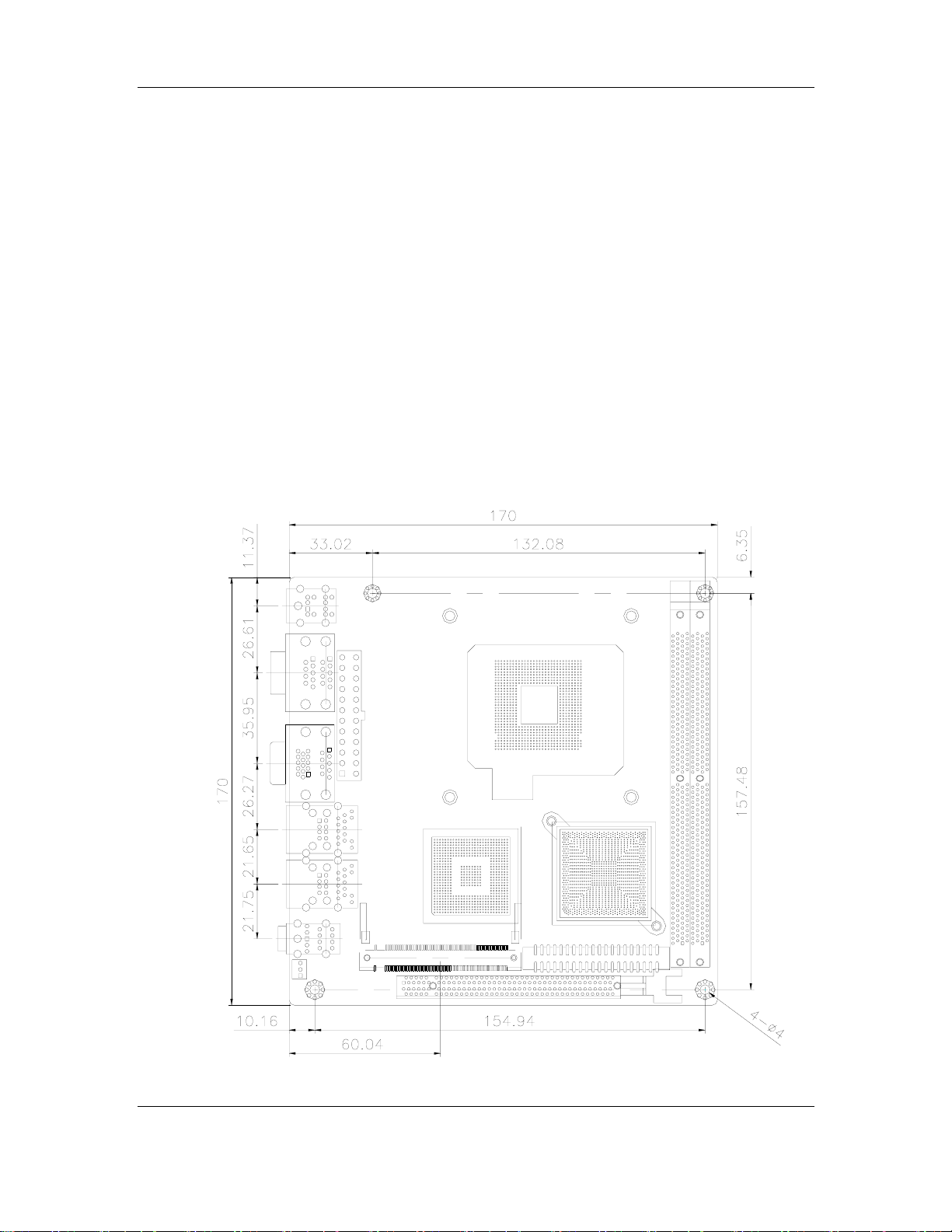
3.2 Dimensions
3.2.1 Board Dimensions
The dimensions of the board are listed below:
Length: 170mm
Width: 170mm
22 ©Copyright 2006 CyberResearch, Inc.
Page 29
CyberResearch® Motherboards MICA Series
Figure 3-1: MICA Series Dimensions (mm)
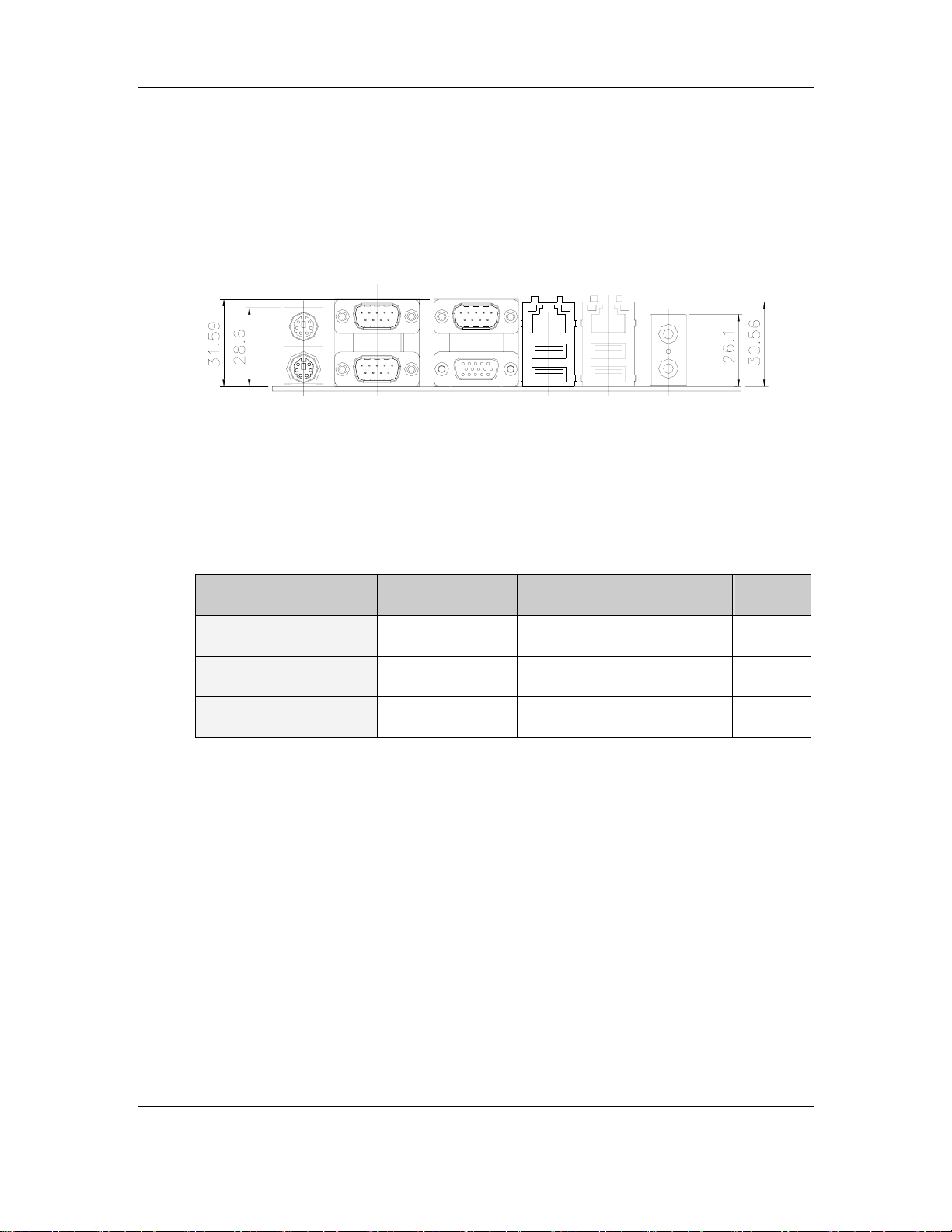
3.2.2 External Interface Panel Dimensions
External interface panel dimensions are shown in Figure 3-2.
Figure 3-2: External Interface Panel Dimensions (mm)
3.3 CPU Support
Table-3-1 lists the CPUs supported by the MICA Series board.
Model Clock Speed L2 Cache Max. FSB Socket
Intel® Pentium® D
Intel® Pentium® 4
Intel® Celeron® D
Table-3-1: Supported CPUs
2.80 to 3.60 GHz 1 to 2 MB 1066 MHz LGA775
2.66 to 3.80 GHz 1 to 2 MB 800 MHz LGA775
2.13 to 3.33 GHz 256 to 512 KB 533 MHz LGA775
3.3.1 Intel® Pentium® D
The Intel® Pentium® D processor comes with the following features:
The two full processing cores make it easy to handle multiple applications,
multimedia entertainment and digital photo editing simultaneously
Intel® Extended Memory 64 Technology (Intel® EM64T) enables the
processor to execute operating systems and applications written to t ake
advantage of the Intel EM64T.
Intel Speedstep® technology allows trad eoffs to be made between
performance and power consumption.
CyberResearch, Inc. 23
25 Business Park Drive P: (203) 483-8815; F: (203) 483-9024
Branford, CT USA www.cyberresearch.com
Page 30

MICA Series CyberResearch® Motherboards
The Execute Disable Bit feature allows memory to be marked as executable
or non-executable.
3.3.2 Intel® Pentium® 4
The Intel® Pentium® 4 processor comes with the following features:
Hyper-threading Technology improves system responsiveness and increases
productivity and efficiency.
Improved Power Management with Enhanced Intel SpeedStep® Technology
Improved performance by allowing the system to address more than 4 GB of
both virtual and physical memory.
Execute Disable Bit prevent certain classes of malicious "buffer overflow"
attacks when combined with a supporting operating system.
3.3.3 Intel® Celeron® D
The Intel® Celeron® D processor comes with the following features:
Intel Extended Memory 64 Technology enhances Intel 32-bit architecture,
giving the processor platform access to larger amounts of memory.
512KB Level 2 Cache enables improved overall system performance by
giving the core faster access to larger amounts of the data used most often.
Streaming SIMD Extensions Accelerates performance on a wide variety of
applications including multimedia, video and audio.
Minimize the acoustic noise levels generated from running the fan at higher
speed for thermal performance.
3.4 On-board Chipset
3.4.1 Intel® 945G Express Chipset
The Intel® 945G Express Chipset consists of the following chipsets preinstalled on the
board:
Intel
Intel
®
82945G GMCH
®
ICH7 ICH
24 ©Copyright 2006 CyberResearch, Inc.
Page 31

CyberResearch® Motherboards MICA Series
The following two sections (Section 3.4.2 and Section 3.4.3) list some of the features of
®
the Intel
chipsets please refer to the Intel website.
82945G and the Intel® ICH7 chipsets. For more information on these two
3.4.2 Intel® 82945G Graphics and Memory Controller Hub
The Intel® 82945G GMCH comes with the following features:
Supports Intel® Viiv™ Technology
PCI Express x16 interface supports the latest high-performance graphics
cards
PCI Express x1 interface delivers faster access to peripheral devices and
networking
Boosts graphics performance to deliver richer visual color and picture clarity
without additional graphics cards
Integrated audio support enables premium sound and deliver features such
as multiple audio streams and jack re-tasking.
Dual-channel DDR2 memory support
3.4.3 Intel® ICH7 I/O Controller Hub
The Intel® ICH7 ICH comes with the following features:
PCI Express
o Four PCI Express root ports
o Supports PCI Express 1.0a
o Support for full 2.5 Gb/s bandwidth in each direction per x1 lane
Integrated serial ATA host controller with data transfer rates up to 3.0 Gb/s
Integrated IDE controller
o Independent timing of up to two dirves
o Ultra ATA/100/66/33, BMIDE and PIC modes
o Tri-state modes to enable swap bay
Integrated LAN controller
o Supports IEEE 802.3
o 10/100 Mb/s Ethernet support
AC-Link for audio and telephony CODECs
Intel Matrix Storage Technology
CyberResearch, Inc. 25
25 Business Park Drive P: (203) 483-8815; F: (203) 483-9024
Branford, CT USA www.cyberresearch.com
Page 32

MICA Series CyberResearch® Motherboards
o Protection against data loss from a hard drive failure
High-speed SATA II storage interface with 3.0 Gb/s transfer rate
Power management logic
o Supports ACPI 3.0
o PCI PME# support
SMBus
o Flexible SMBus/SMLink architecture to optimize for ASF
o Provides independent manageability bus through SMLink interface
o Support SMBus 2.0 Specification
3.5 Graphics Support
The graphics features listed below are all integrated on the Intel 82945G GMCH.
Built-in support of consumer electronic displays allows native high-definition
displays with 720p or 1080i resolutions
Support for dual-independent display
Enhance modes for wide screen flat panels and optimized 3D
Support ADD2 and Media Expansion Cards (MECs)
o Combine several video output options (DVI, dual independent display,
component, composite, HDTV and LVDS) in a single-card solution
o MECs enable video input capability and PVR functionality
o Support a wide range of display types and configurations
3.6 Memory Support
The MICA Series has two DDR2 DIMM sockets and supports two 400MHz, 533MHz or
667MHz DDR2 DIMM with a maximum RAM of up to 2GB.
3.7 PCI Bus Interface Support
The PCI bus on the MICA Series has the following features:
33MHz Revision 2.3 is implemented
64-bit addressing on PCI using DAC protocol is supported
3.8 GbE Ethernet
26 ©Copyright 2006 CyberResearch, Inc.
Page 33

CyberResearch® Motherboards MICA Series
The BCM5787 is a seventh generation 10/100/1000BASE-T Ethernet LAN controller
solution for high performance network applications. The device combines a triple-speed
IEEE 802.3 compliant Media Access Controller (MAC) with a triple-speed Ethernet
transceiver, PCIe bus interface, and on-chip buffer memory in a single device. The device
is fabricated in a 1.2V CMOS process providing a low-power system solution. The GbE
controller features are below.
Integrated 10/100/1000 transceiver
10/100/1000 full/half-duplex MAC
Automatic MDI crossover function
Supports PCIe v1.0a
Wake-on-LAN support meeting the ACPI requirements
Statistics for SNMP MIB II, Ethernet-like MIB and Ethernet MIB (802.3z,
clause 30)
Serial EEPROM or serial flash supported
JT A G sup po rted
196-FBGA package
3.9 Drive Interfaces
The MICA Series can support the following drive interfaces.
4 x SATA drives
2 x IDE devices
3.9.1 SATA Drives
The MICA Series supports four SATA II drives with transfer rates of up to 3.0 Gb/s.
3.9.2 IDE Interfaces
The MICA Series IDE controller supports up to two IDE devices with the following
specifications:
Supports PIO IDE transfers up to 16MB/s
Supports Ultra ATA 100 devices with data transfer rates up to 100MB/s
CyberResearch, Inc. 27
25 Business Park Drive P: (203) 483-8815; F: (203) 483-9024
Branford, CT USA www.cyberresearch.com
Page 34

MICA Series CyberResearch® Motherboards
3.10 Serial Ports
The MICA Series has four high-speed UART serial ports. The serial ports have the
following specifications.
16C550 UART with 16-byte FIFO buffer
115.2Kbps transmission rate
3.11 Real Time Clock
256-byte battery backed CMOS SRAM
3.12 Infrared Data Association (IrDA) Interface
The MICA Series IrDA supports the following interfaces.
Serial Infrared (SIR)
Shift Keyed Infrared (ASKIR)
If an IrDA port is need, COM2 must be configured as either SIR or ASKIR mode in the
BIOS under Super IO devices. Normal RS-232 COM2 is then disabled.
3.13 USB Interfaces
The MICA Series supports eight USB interfaces, four internal and four external. The USB
interfaces support USB 2.0.
3.14 BIOS
The MICA Series uses a licensed copy of AMI BIOS. The features of the flash BIOS used
are listed below:
SMIBIOS (DMI) compliant
Console redirection function support
PXE (Pre-Boot Execution Environment ) support
USB booting support
3.15 Operating Temperature and Temperature Control
28 ©Copyright 2006 CyberResearch, Inc.
Page 35

CyberResearch® Motherboards MICA Series
The maximum and minimum operating temperatures for the MICA Series are listed bel ow.
Minimum Operating Temperature: 0ºC (32°F)
Maximum Operating Temperature: 60°C (140°F)
A cooling fan and heat sink must be installed on the CPU. Thermal paste must be
smeared on the lower side of the heat sink before it is mounted on the CPU. Heat sinks
are also mounted on the chipsets to ensure the operating temperature of these chips
remain low.
3.16 Audio Codec
The MICA Series has an integrated REALTEK ALC655 CODEC. The ALC655 CODEC is
a 16-bit, full-duplex AC'97 Rev. 2.3 compatible six-channel audio CODEC designed for PC
multimedia systems, including host/soft audio and AMR/CNR-based designs. Some of the
features of the codec are listed below.
Meets performance requirements for audio on PC99/2001 systems
Meets Microsoft WHQL/WLP 2.0 audio requirements
16-bit Stereo full-duplex CODEC with 48KHz sampling rate
Compliant with AC'97 Rev 2.3 specifications
Front-Out, Surround-Out, MIC-In and LINE-In Jack Sensing
14.318MHz -> 24.576MHz PLL to eliminate crystal
12.288MHz BITCLK input
Integrated PCBEEP generator to save buzzer
Interrupt capability
Three analog line-level stereo inputs with 5-bit volume control, LINE_IN, CD,
AUX
High-quality differential CD input
Two analog line-level mono inputs: PCBEEP , PHONE-IN
Two software selectable MIC inputs
Dedicated Front-MIC input for front panel applications (software selectable)
Boost preamplifier for MIC input
LINE input shared with surround output; MIC input shared with Center and
LFE output
Built-in 50mW/20ohm amplifier for both Front-out and Surround-Out
CyberResearch, Inc. 29
25 Business Park Drive P: (203) 483-8815; F: (203) 483-9024
Branford, CT USA www.cyberresearch.com
Page 36

MICA Series CyberResearch® Motherboards
External Amplifier Power Down (EAPD) capability
Power management and enhanced power saving features
Supports Power-Off CD function
Adjustable VREFOUT control
Supports 48KHz S/PDIF output, complying with AC'97 Rev 2.3 specifications
Supports 32K/44.1K/48KHz S/PDIF input
Power support: Digital: 3.3V; Analog: 3.3V/5V
Standard 48-pin LQFP package
EAX™ 1.0 & 2.0 compatible
Direct Sound 3D™ compatible
A3D™ compatible
I3DL2 compatible
HRTF 3D positional audio
10-band software equalizer
Voice can cellation and key shifting in Karaoke mode
AVRack® Media Player
Configuration Panel for improved user convenience
3.17 Power Consumption
Table 3-2 shows the power consumption parameters for the MICA Series when a Pentium
4 processor with a clock speed of 3.06GHz is running with four DDR2 533MHz 1GB DIMM
module.
Voltage Current
+5V 1.8A
+12V 5.81A
+3.3V 3.49A
5VSB 0.37A
Table 3-2: Power Consumption
3.18 Packaged Contents and Optional Accessory Items
3.18.1 Package Contents
30 ©Copyright 2006 CyberResearch, Inc.
Page 37

CyberResearch® Motherboards MICA Series
The MICA Series is shipped with the following components.
1 x MICA Series single board computer
1 x IDE flat cable
2 x SATA cables
1 x SATA power cable
1 x I/O shielding
1 x Mini jumper pack
1 x Utility CD
1 x Quick Installation Guide
3.18.2 Optional Accessory Items
The items shown in the list below are optional accessory items are purchased separately.
ATI M56P mobile grade PCI Express Graphic Card with VGA, DVI, 1080i
HDTV and dual channel 24-bit LVDS interface
RS-232/422/485 cable
USB cable
CPU cooler
CyberResearch, Inc. 31
25 Business Park Drive P: (203) 483-8815; F: (203) 483-9024
Branford, CT USA www.cyberresearch.com
Page 38

MICA Series CyberResearch® Motherboards
32 ©Copyright 2006 CyberResearch, Inc.
Page 39

CyberResearch® Motherboards MICA Series
Chapter
3
4 Connectors and
Jumpers
CyberResearch, Inc. 33
25 Business Park Drive P: (203) 483-8815; F: (203) 483-9024
Branford, CT USA www.cyberresearch.com
Page 40

MICA Series CyberResearch® Motherboards
4.1 Peripheral Interface Connectors
Section 4.1.1 shows peripheral interface connector locations. Section 4.1.2 lists all the
peripheral interface connectors seen in Section 4.1.1.
4.1.1 MICA Series Layout
Figure 4-1 shows the on-board peripheral connectors, backplane peripheral connectors
and on-board jumpers.
Figure 4-1: Connector and Jumper Locations
34 ©Copyright 2006 CyberResearch, Inc.
Page 41

CyberResearch® Motherboards MICA Series
4.1.2 Peripheral Interface Connectors
Table 4-1 shows a list of the peripheral interface connectors on the MICA Series. Detailed
descriptions of these connectors can be found in Section 4.2.
Connector Type Label
ATX + CPU 12V power connector 4-pin header CPU12V1
DDR2 DIMM socket 240-pin slot DIMM1
DDR2 DIMM socket 240-pin slot DIMM2
Fan connector (CPU) 4-pin header CPUFAN1
Fan connector (System) 3-pin header SYSFAN1
Front panel connector 14-pin header F_PANEL1
Digital Input/Output connector 10-pin header DIO1
IDE Interface connector 40-pin header IDE1
IR Interface connector 5-pin header IR1
Mini PCI connector 124-pin Mini PCI Type III slot MPCI1
PCI Express x16 socket PCI Express x16 slot PCIE1
Power connector 24-pin connector PWR1
Serial port connector 14-pin header COM3
SATA drive connector (1) 7-pin SATA connector SATA_P0
SATA drive connector (2) 7-pin SATA connector SATA_P1
SATA drive connector (3) 7-pin SATA connector SATA_S0
SATA drive connector (4) 7-pin SATA connector SATA_S1
TPM connector 20-pin header TPM1
USB connector (1) 8-pin header USB1
CyberResearch, Inc. 35
25 Business Park Drive P: (203) 483-8815; F: (203) 483-9024
Branford, CT USA www.cyberresearch.com
Page 42

MICA Series CyberResearch® Motherboards
USB connector (2) 8-pin header USB2
Table 4-1: Peripheral Interface Connectors
4.1.3 Rear Panel Connectors
Table 4-2 lists the rear panel connectors on the MICA Series. Detailed descriptions of
these connectors can be found in Section 4.3.
Connector Type Label
Audio Jacks Audio connector CN3
CRT connector 15-pin female connector CN5
Ethernet connector (1) RJ-45 connector CN1
Ethernet connector (2) RJ-45 connector CN2
Keyboard/Mouse connector 6-pin mini din connector KBMS1
Serial port connector (1) DB-9 male connector CN4
Serial port connector (2) DB-9 male connector CN4
Serial port connector (3) DB-9 male connector CN5
USB 2.0 port (1) USB port connector CN1
USB 2.0 port (2) USB port connector CN2
Table 4-2: Rear Panel Connectors
4.1.4 On-board Jumpers
Table 4-3 lists the on-board jumpers. Detailed descriptions of these jumpers can be found
in Section 5.6.
Description Label Type
Clear CMOS JP5 2-pin header
36 ©Copyright 2006 CyberResearch, Inc.
Page 43

CyberResearch® Motherboards MICA Series
COM2 mode selection JP2 3-pin header
Table 4-3: On-board Jumpers
4.2 Internal Peripheral Connectors
Internal peripheral connectors are found on the motherboard and are only accessible
when the motherboard is outside of the chassis. T his sect ion h as c omplete des cript ion s of
all the internal, peripheral connectors on the MICA Series.
4.2.1 ATX + CPU 12V Power Connector
CN Label: CPU12V1
CN Type: 4-pin headers (1x4)
CN Location: See Figure 4-2
CN Pinouts: See Table 4-4
The connector supports the 12V power supply.
Figure 4-2: CPU 12V Power Connector Location
PIN NO. DESCRIPTION PIN NO. DESCRIPTION
CyberResearch, Inc. 37
25 Business Park Drive P: (203) 483-8815; F: (203) 483-9024
Branford, CT USA www.cyberresearch.com
Page 44

MICA Series CyberResearch® Motherboards
1 GND 2 GND
3 +12V 4 +12V
Table 4-4: CPU 12V Power Connector Pinouts
4.2.2 Fan Connectors
CN Label: CPUFAN1 and SYSFAN1
CN Type: 4-pin header and 3-pin header
CN Location: See Figure 4-3
CN Pinouts: See Table 4-5 and Table 4-6
The cooling fan connectors on the MICA Series provide a 12V, 500mA current to a CPU
cooling fan and a system cooling fan. All cooling fans have linear fan speed controlled by
BIOS.
Figure 4-3: Fan Connector Locations
PIN NO. DESCRIPTION
38 ©Copyright 2006 CyberResearch, Inc.
Page 45

CyberResearch® Motherboards MICA Series
1 Ground
2 +12V
3 Rotation Signal
4 Control
Table 4-5: CPU Fan Connector Pinouts
PIN NO. DESCRIPTION
1 Ground
2 +12V
3 Rotation Signal
Table 4-6: System Fan Connector Pinouts
4.2.3 Front Panel Connector
CN Label: F_PANEL1
CN Type: 14-pin header (2x7)
CN Location: See Figure 4-4
CN Pinouts: See Table 4-7
The front panel connector connects to several external switches and indicators to monitor
and control the motherboard. These indicators and switches include:
Power
ATX Power button
Reset button
Speaker
HDD
CyberResearch, Inc. 39
25 Business Park Drive P: (203) 483-8815; F: (203) 483-9024
Branford, CT USA www.cyberresearch.com
Page 46

MICA Series CyberResearch® Motherboards
Figure 4-4: Front Panel Connector Location
PIN NO. DESCRIPTION PIN NO. DESCRIPTION
1 LED+ 2 BUZZER3 N/C 4 N/C
5 LED- (GND) 6 N/C
7 POWER BUTTON- 8 VCC
9 POWER BUTTON+ 10 N/C
11 IDE_LED+ 12 RESET
13 IDE_LED - 14 GND
Table 4-7: Front Panel Connector Pinouts
4.2.4 Digital Input/Output Connector
CN Label: DIO1
CN Type: 10-pin header (2x5)
CN Location: See Figure 4-5
CN Pinouts: See Table 4-8
40 ©Copyright 2006 CyberResearch, Inc.
Page 47

CyberResearch® Motherboards MICA Series
The DIO connector is managed through a Super I/O chip. The DIO connector pins are
user programmable. The digital IO port of MICA Series is 5V CMOS level.
Figure 4-5: Digital I/O Connector Location
PIN NO. DESCRIPTION PIN NO. DESCRIPTION
1 GROUND 2 VCC
3 DGPI0 4 DGPO0
5 DGPI1 6 DGPO1
7 DGPI2 8 DGPO2
9 DGPI3 10 DGPO3
Table 4-8: Digital I/O Connector Pinouts
4.2.5 IDE Connector
CN Label: IDE1
CN Type: 40-pin header (2x20)
CN Location: See Figure 4-6
CN Pinouts: See Table 4-9
CyberResearch, Inc. 41
25 Business Park Drive P: (203) 483-8815; F: (203) 483-9024
Branford, CT USA www.cyberresearch.com
Page 48

MICA Series CyberResearch® Motherboards
One primary 40-pin IDE device connector on the MICA Series motherboard supports
connectivity to ATA 100 IDE devices with data transfer rates up to 100MB/s.
Figure 4-6: IDE Device Connector Location
PIN NO. DESCRIPTION PIN NO. DESCRIPTION
1 RESET# 2 GROUND
3 DATA 7 4 DATA 8
5 DATA 6 6 DATA 9
7 DATA 5 8 DATA 10
9 DATA 4 10 DATA 11
11 DATA 3 12 DATA 12
13 DATA 2 14 DATA 13
15 DATA 1 16 DATA 14
17 DATA 0 18 DATA 15
19 GROUND 20 N/C
21 DRQ 22 GROUND
42 ©Copyright 2006 CyberResearch, Inc.
Page 49

CyberResearch® Motherboards MICA Series
PIN NO. DESCRIPTION PIN NO. DESCRIPTION
23 IOW# 24 GROUND
25 IOR# 26 GROUND
27 CHRDY 28 REV. PULL LOW
29 DACK 30 GROUND-DEFAULT
31 INTERRUPT 32 N/C
33 SA1 34 N/C
35 SA0 36 SA2
37 HDC CS0# 38 HDC CS1#
39 HDD ACTIVE# 40 GROUND
Table 4-9: IDE Connector Pinouts
4.2.6 IR Interface Connector
CN Label: IR1
CN Type: 5-pin header (1x5)
CN Location: See Figure 4-7
CN Pinouts: See Table 4-10
The integrated infrared (IrDA) connector supports both Serial Infrared (SIR) and Amplitude
Shift Key Infrared (ASKIR) interfaces.
CyberResearch, Inc. 43
25 Business Park Drive P: (203) 483-8815; F: (203) 483-9024
Branford, CT USA www.cyberresearch.com
Page 50

MICA Series CyberResearch® Motherboards
Figure 4-7: IR Connector Location
PIN NO. DESCRIPTION
1 VCC
2 NC
3 IR-RX
4 Ground
5 IR-TX
Table 4-10: IR Connector Pinouts
4.2.7 Mini PCI Slot
CN Label: MPCI1
CN Type: 124-pin Mini PCI Type III slot
CN Location: See Figure 4-8
CN Pinouts: See Table 4-11
Mini PCI is a small form factor version of a PCI card. Mini PCI expansion devices can be
inserted into the Mini PCI slot.
44 ©Copyright 2006 CyberResearch, Inc.
Page 51

CyberResearch® Motherboards MICA Series
Figure 4-8: Mini PCI Slot Location
PIN NAME PIN NAME PIN NAME PIN NAME
1 TIP 32 GROUND 63 3.3V 94 AD[02]
2 RING 33 AD[31] 64 FRAME# 95 AD[03]
3 8PMJ-3 34 PME# 65 CLKRUN# 96 AD[00]
4 8PMJ-1 35 AD[29] 66 TRDY# 97 5V
5 8PMJ-6 36 RESERVED 67 SERR# 98 RESERVED_WIP5
6 8PMJ-2 37 GROUND 68 STOP# 99 AD[01]
7 8PMJ-7 38 AD[30] 69 GROUND 100 RESERVED_WIP5
8 8PMJ-4 39 AD[27] 70 3.3V 101 GROUND
9 8PMJ-8 40 3.3V 71 PERR# 102 GROUND
10 8PMJ-5 41 AD[25] 72 DEVSEL# 103 AC_SYNC
11 LED1_GRNP 42 AD[28] 73 C/BE[1]# 104 M66EN
12 LED2_YELP 43 RESERVED 74 GROUND 105 AC_SDATA_IN
13 LED1_GRNN 44 AD[26] 75 AD[14] 106 AC_SDATA_OUT
14 LED2_YELN 45 C/BE[3]# 76 AD[15] 107 AC_BIT_CLK
15 CHSGND 46 AD[24] 77 GROUND 108 AC_CODEC_ID0#
CyberResearch, Inc. 45
25 Business Park Drive P: (203) 483-8815; F: (203) 483-9024
Branford, CT USA www.cyberresearch.com
Page 52

MICA Series CyberResearch® Motherboards
16 RESERVED 47 AD[23] 78 AD[13] 109 AC_CODEC_ID 1#
17 INTB# 48 IDSEL 79 AD[12] 110 AC_RESET#
18 5V 49 GROUND 80 AD[11] 111 MOD_AUDIO_MON
19 3.3V 50 GROUND 81 AD[10] 112 RESERVED
20 INTA# 51 AD[21] 82 GROUND 113 AUDIO_GND
21 RESERVED 52 AD[22] 83 GROUND 114 GROUND
22 RESERVED 53 AD[19] 84 AD[09] 115 SYS_AUDIO_OUT
23 GROUND 54 AD[20] 85 AD[08] 116 SYS_AUDIO_IN
24 3.3VAUX 55 GROUND 86 C/BE[0]# 117 SYS_AUDIO_OUT GND
25 CLK 56 PAR 87 AD[07] 118 SYS_AUDIO_IN GND
26 RST# 57 AD[17] 88 3.3V 119 AUDIO_GND
27 GROUND 58 AD[18] 89 3.3V 120 AUDIO_GND
28 3.3V 59 C/BE[2]# 90 AD[06] 121 RESERVED
29 REQ# 60 AD[16] 91 AD[05] 122 MPCIACT#
30 GNT# 61 IRDY# 92 AD[04] 123 VCC5VA
31 3.3V 62 Ground 93 RESERVED 124 3.3VAUX
Table 4-11: Mini PCI Slot Pinouts
4.2.8 PCI Express x16 Slot
CN Label: PCIE1
CN Type: 164-pin PCIe x16 slot
CN Location: See Figure 4-9
CN Pinouts: See Table 4-12 (Side A) Table 4-13 (Side B)
PCIe x16 expansion devices can be inserted into the PCIe x16 slot.
46 ©Copyright 2006 CyberResearch, Inc.
Page 53

CyberResearch® Motherboards MICA Series
Figure 4-9: PCI Express x16 Slot Location
PIN NAME PIN NAME PIN NAME PIN NAME
A1 Name A22 HSIn(1) A43 HSIp(6) A64 HSIp(11)
A2 PRSNT#1 A23 GND A44 HSIn(6) A65 HSIn(11)
A3 +12v A24 GND A45 GND A66 GND
A4 +12v A25 HSIp(2) A46 GND A67 GND
A5 GND A26 HSIn(2) A47 HSIp(7) A68 HSIp(12)
A6 JTAG2 A27 GND A48 HSIn(7) A69 HSIn(12)
A7 JTAG3 A28 GND A49 GND A70 GND
A8 JTAG4 A29 HSIp(3) A50 RSVD A71 GND
A9 JTAG5 A30 HSIn(3) A51 GND A72 HSIp(13)
A10 +3.3v A31 GND A52 HSIp(8) A73 HSIn(13)
A11 +3.3v A32 RSVD A53 HSIn(8) A74 GND
A12 PWRGD A33 RSVD A54 GND A75 GND
CyberResearch, Inc. 47
25 Business Park Drive P: (203) 483-8815; F: (203) 483-9024
Branford, CT USA www.cyberresearch.com
Page 54

MICA Series CyberResearch® Motherboards
A13 GND A34 GND A55 GND A76 HSIp(14)
A14 REFCLK+ A35 HSIp(4) A56 HSIp(9) A77 HSIn(14)
A15 REFCLK- A36 HSIn(4) A57 HSIn(9) A78 GND
A16 GND A37 GND A58 GND A79 GND
A17 HSIp(0) A38 GND A59 GND A80 HSIp(15)
A18 HSIn(0) A39 HSIp(5) A60 HSIp(10) A81 HSIn(15)
A19 GND A40 HSIn(5) A61 HSIn(10) A82 GND
A20 RSVD A41 GND A62 GND
A21 GND A42 GND A63 GND
Table 4-12: PCIe x16 Side A Pinouts
PIN NAME PIN NAME PIN NAME PIN NAME
B1 +12v B22 GND B43 GND B64 GND
B2 +12v B23 HSOp(2) B44 GND B65 GND
B3 RSVD B24 HSOn(2) B45 HSOp(7) B66 HSOp(12)
B4 GND B25 GND B46 HSOn(7) B67 HSOn(12)
B5 SMCLK B26 GND B47 GND B68 GND
B6 SMDAT B27 HSOp(3) B48 PRSNT#2 B69 GND
B7 GND B28 HSOn(3) B49 GND B70 HSOp(13)
B8 +3.3v B29 GND B50 HSOp(8) B71 HSOn(13)
B9 JTAG1 B30 RSVD B51 HSOn(8) B72 GND
B10 3.3Vaux B31 PRSNT#2 B52 GND B73 GND
B11 WAKE# B32 GND B53 GND B74 HSOp(14)
B12 RSVD B33 HSOp(4) B54 HSOp(9) B75 HSOn(14)
B13 GND B34 HSOn(4) B55 HSOn(9) B76 GND
B14 HSOp(0) B35 GND B56 GND B77 GND
B15 HSOn(0) B36 GND B57 GND B78 HSOp(15)
B16 GND B37 HSOp(5) B58 HSOp(10) B79 HSOn(15)
B17 PRSNT#2 B38 HSOn(5) B59 HSOn(10) B80 GND
B18 GND B39 GND B60 GND B81 PRSNT#2
B19 HSOp(1) B40 GND B61 GND B82 RSVD#2
B20 HSOn(1) B41 HSOp(6) B62 HSOp(11)
B21 GND B42 HSOn(6) B63 HSOn(11)
48 ©Copyright 2006 CyberResearch, Inc.
Page 55

CyberResearch® Motherboards MICA Series
Table 4-13: PCIe x16 Side B Pinouts
4.2.9 ATX Power Connector
CN Label: PWR1
CN Type: 24-pin connector
CN Location: See Figure 4-10
CN Pinouts: See Table 4-14
This 24-pin power connector supports the ATX powe r supply.
Figure 4-10: Power Connector Location
CyberResearch, Inc. 49
25 Business Park Drive P: (203) 483-8815; F: (203) 483-9024
Branford, CT USA www.cyberresearch.com
Page 56

MICA Series CyberResearch® Motherboards
PIN NO. DESCRIPTION PIN NO. DESCRIPTION
1 +3.3V 13 Ground
2 +3.3V 14 PS-ON
3 Ground 15 Ground
4 +5V 16 Ground
5 Ground 17 Ground
6 5V 18 NC
7 Ground 19 +5V
8 Power Good 20 +5V
9 +5VSB 21 +12V
10 +12V 22 +5V
11 +3.3V 23 +3.3V
12 -12V 24 Ground
Table 4-14: Power Connector Pinouts
4.2.10 Serial Port Connector
CN Label: COM3
CN Type: 14-pin header (2x5)
CN Location: See Figure 4-11
CN Pinouts: See Table 4-15
The serial ports connectors connect to RS-232 or RS-422/485 serial port device.
50 ©Copyright 2006 CyberResearch, Inc.
Page 57

CyberResearch® Motherboards MICA Series
Figure 4-11: Serial Port Connector Location
PIN NO. DESCRIPTION PIN NO. DESCRIPTION
1 DCD 2 DSR
3 RXD 4 RTS
5 TXD 6 CTS
7 DTR 8 RI
9 GROUND 10 NC
11 TX+ 12 TX-
13 RX+ 14 RX-
Table 4-15: Serial Port Connector Pinouts
4.2.11 SATA Drive Connectors
CN Label: SATA_P0, SATA _P1, SAT A_S0 and SATA_S1
CN Type: 1x7 pin SATA drive connectors
CN Location: See Figure 4-12
CyberResearch, Inc. 51
25 Business Park Drive P: (203) 483-8815; F: (203) 483-9024
Branford, CT USA www.cyberresearch.com
Page 58

MICA Series CyberResearch® Motherboards
CN Pinouts: See Table 4-16
The four SATA drive connectors are connected to four SATA II drives. SATA II drives
transfer data at speeds as high as 3.0Gb/s.
Figure 4-12: SATA Drive Connector Locations
PIN NO. DESCRIPTION
1 GND
2 TXP
3 TXN
4 GND
5 RXN
6 RXP
7 GND
Table 4-16: SATA Drive Connector Pinouts
4.2.12 TPM Connector
52 ©Copyright 2006 CyberResearch, Inc.
Page 59

CyberResearch® Motherboards MICA Series
CN Label: TPM1
CN Type: 20-pin connector
CN Location: See Figure 4-13
CN Pinouts: See Table 4-17
The TPM (Trusted Platform Module) connector is a device with a controller that is used to
check authenticity of digital signs and keys as well as other encryption and security
functions.
Figure 4-13: TPM Connector Location
PIN NO. DESCRIPTION PIN NO. DESCRIPTION
1 Clock 2 GND
3 Frame# 4 KEY
5 Reset# 6 +5V
7 LAD3 8 LAD2
9 +3.3V 10 LAD1
11 LAD0 12 GND
CyberResearch, Inc. 53
25 Business Park Drive P: (203) 483-8815; F: (203) 483-9024
Branford, CT USA www.cyberresearch.com
Page 60

MICA Series CyberResearch® Motherboards
13 SCL 14 SDA
15 +3.3V SBY 16 Serial IRQ
17 GND 18 NC
19 Power Down# 20 DRQ#
Table 4-17: TPM Connector Pinouts
4.2.13 Internal USB Connectors
CN Label: USB1 and USB2
CN Type: 8-pin header (2x4)
CN Location: See Figure 4-14
CN Pinouts: See Table 4-18
One 2x4 pin connector provides connectivity to two USB 2.0 ports. The USB ports are
used for I/O bus expansion.
Figure 4-14: Internal USB Connector Locations
PIN NO. DESCRIPTION PIN NO. DESCRIPTION
54 ©Copyright 2006 CyberResearch, Inc.
Page 61

CyberResearch® Motherboards MICA Series
1 USB Power 5 GND
2 DATA- 6 DATA+
3 DATA+ 7 DATA4 GND 8 USB Power
Table 4-18: USB1 and USB2 Pinouts
4.3 External Interface Connectors
The peripheral connectors on the back panel are connected to devices externally when
the MICA Series is installed in a chassis. The peripheral connectors on the rear panel are:
2 x Audio jacks
1 x CRT connector
2 x RJ-45 Ethernet connectors
2 x Keyboard/mouse connectors
3 x Serial port connectors
4 x USB 2.0 connectors
Figure 4-15: MICA Series External Interface Connectors
4.3.1 Audio Connectors
CN Label: CN3
CyberResearch, Inc. 55
25 Business Park Drive P: (203) 483-8815; F: (203) 483-9024
Branford, CT USA www.cyberresearch.com
Page 62

MICA Series CyberResearch® Motherboards
CN Type: Audio jack
CN Location: See Figure 4-15 (labeled number 7)
CN Pinouts: See Figure 4-16
Line Out port (Lime): Connects to a headp hone or a speaker. With
multi-channel configurations, this port can also connect to front speakers.
Microphone (Pink): Connects a microphone.
Figure 4-16: Audio Connector
4.3.2 CRT Connector
CN Label: CN5
CN Type: 15-pin female connector
CN Location: See Figure 4-15 (labeled number 8)
CN Pinouts: See Table 4-19
The standard 15-pin VGA connector connects to a CRT or LCD display monitor.
56 ©Copyright 2006 CyberResearch, Inc.
Page 63

CyberResearch® Motherboards MICA Series
Figure 4-17: VGA Connector
PIN NO. DESCRIPTION PIN NO. DESCRIPTION
1 RED 2 GREEN
3 BLUE 4 NC
5 GND 6 GND
7 GND 8 GND
9 VCC/NC 10 GND
11 NC 12 DDC DAT
13 HSYNC 14 VSYNC
15 DDCCLK
Table 4-19: VGA Connector Pinouts
4.3.3 Ethernet Connectors
CN Label: CN1 and CN2
CN Type: RJ-45
CN Location: See Figure 4-15 (labeled number 4 and 6)
CN Pinouts: See Table 4-20
The MICA Series is equipped with two built-in GbE Ethernet controllers. The controllers
can connect to the LAN through two RJ-45 LAN connectors. There are two LEDs on the
connector indicating the status of LAN. The pin assignments are listed in the following
table:
PIN DESCRIPTION PIN DESCRIPTION
2 TX0+ 8 TX3+
3 TX0- 9 TX3-
4 TX1+ 11 Active5 TX2+ 12 Active+(Yellow)
6 TX2- 13 LINK (Green-10/100M)
CyberResearch, Inc. 57
25 Business Park Drive P: (203) 483-8815; F: (203) 483-9024
Branford, CT USA www.cyberresearch.com
Page 64

MICA Series CyberResearch® Motherboards
7 TX1- 14 LINK (Orange-1G)
Table 4-20: LAN1 and LAN2 Pinouts
Figure 4-18: RJ-45 Ethernet Connector
The RJ-45 Ethernet connector has two status LEDs, one green and one yello w. The green
LED indicates activity on the port and the yellow LED indicates the port is linked. See
Table 4-21.
SPEED LED ACT/LINK LED
STATUS DESCRIPTION STATUS DESCRIPTION
GREEN 10/100Mbps connection YELLOW Linked
ORANGE 1Gbps connection BLINKING Data Activity
Table 4-21: RJ-45 Ethernet Connector LEDs
4.3.4 Keyboard/Mouse Connector
CN Label: KBMS1
CN Type: PS/2 connector
CN Location: See Figure 4-15 (labeled number 1)
CN Pinouts: See Table 4-22
The MICA Series keyboard and mouse connectors are standard PS/2 connectors.
58 ©Copyright 2006 CyberResearch, Inc.
Page 65

CyberResearch® Motherboards MICA Series
Figure 4-19: PS/2 Pinouts
PIN DESCRIPTION PIN DESCRIPTION
1 KB DATA 7 MS DATA
2 NC 8 NC
3 GROUND 9 GROUND
4 KB VCC 10 MS VCC
5 KB CLOCK 11 MS CLOCK
6 NC 12 NC
Table 4-22: PS/2 Connector Pinouts
4.3.5 Serial Port Connectors
CN Label: CN4 and CN5
CN Type: DB-9
CN Location: See Figure 4-15 (labeled number 2)
CN Pinouts: See Table 4-23
The serial ports can be connected to a serial communications device directly.
CyberResearch, Inc. 59
25 Business Park Drive P: (203) 483-8815; F: (203) 483-9024
Branford, CT USA www.cyberresearch.com
Page 66

MICA Series CyberResearch® Motherboards
Figure 4-20: External Serial Port Connector
PIN Description
1 DATA CARRIER DETECT (DCD)
2 RECEIVE DATA (RXD)
3 TRANSMIT DATA (TXD)
4 DATA TERMINAL READY (DTR)
5 GROUND (GND)
6 DATA SET READY (DSR)
7 REQUEST TO SEND (RTS)
8 CLEAR TO SEND (CTS)
9 RING INDICATOR (RI)
Table 4-23: External Serial Port Pinouts
4.3.6 USB Connectors
CN Label: CN1 and CN2
CN Type: USB port
CN Location: See Figure 4-15 (labeled number 3 and 5)
CN Pinouts: See Table 4-24
USB devices can be connected directly to the USB connectors on the rear panel.
PIN NO. DESCRIPTION PIN NO. DESCRIPTION
1 VCC 5 VCC
2 DATA6- 6 DATA7-
60 ©Copyright 2006 CyberResearch, Inc.
Page 67

CyberResearch® Motherboards MICA Series
3 DATA6+ 7 DATA7+
4 GROUND 8 GROUND
Table 4-24: External USB Connector Pinouts
CyberResearch, Inc. 61
25 Business Park Drive P: (203) 483-8815; F: (203) 483-9024
Branford, CT USA www.cyberresearch.com
Page 68

MICA Series CyberResearch® Motherboards
62 ©Copyright 2006 CyberResearch, Inc.
Page 69

CyberResearch® Motherboards MICA Series
Chapter
4
5 Installation and
Configuration
CyberResearch, Inc. 63
25 Business Park Drive P: (203) 483-8815; F: (203) 483-9024
Branford, CT USA www.cyberresearch.com
Page 70

MICA Series CyberResearch® Motherboards
5.1 Anti-static Precautions
Electrostatic discharge (ESD) can cause serious damage to electronic components,
including the MICA Series. (Dry climates are especially susceptible to ESD.) It is therefore
critical that whenever the MICA Series (or any other electrical component) is handled, the
following anti-static precautions are strictly adhered to.
Wear an anti-static wrist band: Wearing a simple anti-static wrist band can
help to prevent ESD from damaging the board.
Self-grounding: Before handling the board touch any grounded conducting
material. During the time the board is handled, frequently touch any
conducting materials that are connected to the ground.
5.2 Installation Considerations
NOTE:
The following installation notices and installation considerations should be
read and understood before the motherboard is installed. All installation
notices pertaining to the installation of the motherboard should be strictly
adhered to. Failing to adhere to these precautions may lead to severe
damage of the motherboard and injury to the person installing the
motherboard.
5.2.1 Installation Notices
Before and during the installation of the MICA Series, please do the following:
Read the user manual
o The user manual provides a complete description of the MICA Series,
installation instructions and configuration options.
Wear an electrostatic discharge cuff (ESD)
o Electronic components are easily damaged by ESD. Wearing an ESD cuff
removes ESD from the body and helps prevent ESD damage.
64 ©Copyright 2006 CyberResearch, Inc.
Page 71

CyberResearch® Motherboards MICA Series
Place the motherboard on an antistatic pad
o When installing or configuring the motherboard, place it on an antistatic
pad. This helps to prevent potential ESD damage.
Turn off all power to the MICA Series
o When working with the motherboard, make sure that it is disconnected
from all power supplies and that no electricity is being fed into the system.
Before and during the installation of the MICA Series DO NOT:
remove any of the stickers on the PCB board. These stickers are required for
warranty validation.
use the product before verifying all the cables and power connectors are
properly connected.
allow screws to come in contact with the PCB circuit, connector pins, or its
components.
5.3 Unpacking
NOTE:
If any of the items listed below are missing when the MICA Series is
unpacked, do not proceed with the installation and contact CyberResearch,
Inc..
5.3.1 Unpacking Precautions
Before installing the MICA Series, unpack the motherboard. Some components on MICA
Series are very sensitive to static electricity and can be damaged by a sudden rush of
power. To protect it from being damaged, follow these precautions:
The user should ground them self to remove any static charge before
touching the MICA Seri es. To do so wear a grounded wrist strap at all times or
frequently touch any conducting materials that is connected to the ground.
Handle the MICA Series by its edges. Do not touch the IC chips, leads or
circuitry if not necessary.
CyberResearch, Inc. 65
25 Business Park Drive P: (203) 483-8815; F: (203) 483-9024
Branford, CT USA www.cyberresearch.com
Page 72

MICA Series CyberResearch® Motherboards
Do not place a PCB on top of an anti-static bag. Only the inside of the bag is safe from
static discharge.
5.3.2 Checklist
When unpacking the MICA Series, please make sure that the package contains the
following items.
1 x MICA Series single board computer
1 x IDE flat cable
2 x SATA cables
1 x SATA power cable
1 x I/O shielding
1 x Mini jumper pack
1 x Utility CD
1 x Quick Installation Guide
PCI Express Graphic Card (optional)
RS-232/422/485 cable (optional)
CPU cooler (optional)
USB cable (optional)
If one or more of these items are missing, please contact CyberResearch, Inc. and do not
proceed any further with the installation.
5.4 MICA Series motherboard Installation
WARNING!
1. Never run the motherboard without an appropriate heat sink and cooler
that can be ordered from CyberResearch.
2. Be sure to use the CPU 12V power conn ector for the CPU power.
WARNING!
Please note that the installation instructions described in this manual should
66 ©Copyright 2006 CyberResearch, Inc.
Page 73

CyberResearch® Motherboards MICA Series
be carefully followed in order to avoid damage to the motherboard components
and injury to the user.
WARNING!
When installing electronic components onto the motherboard always take the
following anti-static precautions in order to prevent ESD damage to the
motherboard and other electronic components like the CPU an d DIMM
modules
The following components must be installed onto the motherboard or connected to the
motherboard during the installation process.
CPU
CPU cooling kit
DDR2 memory modules
Peripheral device connection
5.5 Socket LGA775 CPU Installation
5.5.1 CPU Selection: HT Functionality Requirements
Enabling Hyper-Threading Technology on your system requires meeting all of the platform
requirements listed below:
CPU: An Intel® Pentium 4 Processor with HT Technology must be installed
Chipset: An Intel® Chipset that supports HT Technology (that has been met
by the MICA Series)
OS: An operating system that has optimizations for HT Technology
5.5.1.1 CPU Installation
WARNING:
CPUs are expensive and sensitive components. When installing the CPU
CyberResearch, Inc. 67
25 Business Park Drive P: (203) 483-8815; F: (203) 483-9024
Branford, CT USA www.cyberresearch.com
Page 74

MICA Series CyberResearch® Motherboards
please be careful not to damage it in anyway. Make sure the CPU is
installed properly and ensure that a heat sink and CPU cooling fan are
properly installed before the MICA Series is run.
If a heat sink and cooling fan are not properly installed both the CPU and
the board may be damaged.
The LGA775 socket is shown in Figure 5-1.
Figure 5-1: Intel LGA775 Socket
WARNING:
When handling the CPU, only hold it on the sides. DO NOT touch the pins
at the bottom of the CPU.
To install Socket LGA775 CPU onto the MICA Series, follow the steps below:
Step 1: Remove the protective cover. Remove the black protective cover by prying it
off the load plate. To remove the protective cover, locate the “REMOVE” sign
and use the fingernail to pry the protective cover off. (See Figure 5-2)
68 ©Copyright 2006 CyberResearch, Inc.
Page 75

CyberResearch® Motherboards MICA Series
Figure 5-2: Remove the CPU Socket Protective Shield
Step 2: Open the socket. Disengage the load lever by pressing the lever down and
slightly outward to clear the retention tab. Rotate the load lever to a fully open
position. Then rotate the load plate towards the opposite directio n. (See Figure
5-3)
Figure 5-3: Open the CPU Socket Load Plate
Step 3: Inspect the CPU socket Make sure there are no bent pins and make sure the
socket contacts are free of foreign material. If any debris is found, remove it with
compressed air.
Step 4: Orientate the CPU properly. Make sure the IHS (Integrated Heat Sink) side is
facing upward.
Step 5: Correctly position the CPU. Match the Pin 1 mark with the cut edge on the
CyberResearch, Inc. 69
25 Business Park Drive P: (203) 483-8815; F: (203) 483-9024
Branford, CT USA www.cyberresearch.com
Page 76

MICA Series CyberResearch® Motherboards
CPU socket.
Step 6: Align the CPU pins. Locate pin 1 and the two orientation notches on the CPU.
Carefully match the two orientation notches on the CPU with the socket
alignment keys.
Step 7: Insert the CPU. Gently insert the CPU into the socket. If the CPU pins are
properly aligned, the CPU should slide into the CPU socket smoothly. See
Figure 5-4.
Figure 5-4: Insert the Socket LGA775 CPU
Step 8: Close the CPU socket. Close the load plate and engage the load lever by
pushing it back to its original position. Secure the load lever under the retention
tab on the side of CPU socket.
Step 9: Connect the CPU power connector . Connect the CPU 12V cable to the CPU
12V power connector after the cooling kit is installed.Step 0:
5.5.2 Socket LGA775 Cooling Kit Installation
WARNING:
It is strongly recommended that you DO NOT use the original heat
70 ©Copyright 2006 CyberResearch, Inc.
Page 77

CyberResearch® Motherboards MICA Series
sink and cooler provided by Intel on the MICA Series.
The MICA Series i s vertical ly mounted on a horizontal backplane, and
Intel’s heat sink does not come with a support bracket on the soldering
side, the PCB may be bent by the weight of the cooling kit.
CyberResearch’s cooling kit includes a support bracket that is combined
with the heat sink mounted on the CPU to counterweigh and balance the
load on both sides of the PCB.
Figure 5-5: CyberResearch LGA-775 Cooling Kit
The CyberResearch LGA775 CPU cooling kit shown in Figure 5-5 is comprised of a CPU
heat sink and a cooling fan.
NOTE:
Do not wipe off (accidentally or otherwise) the pre-sprayed layer of thermal
paste on the bottom of the heat sink. The thermal paste between the CPU
and the heat sink is important for optimum heat dissipation.
To install the cooling kit follow the instructions below.
Step 1: Place the cooling kit onto the socket LGA775 CPU. Make sure the CPU
cable can be properly routed when the cooling kit is installed.
CyberResearch, Inc. 71
25 Business Park Drive P: (203) 483-8815; F: (203) 483-9024
Branford, CT USA www.cyberresearch.com
Page 78

MICA Series CyberResearch® Motherboards
Step 2: Properly align the cooling kit. Make sure the four spring screw fasteners can
pass through the pre-drilled holes on the PCB.
Step 3: Mount the cooling kit. Gently place the cooling kit on top of the CPU. Make
sure the four threaded screws on the corners of the cooling kit properly pass
through the predrilled holes on the bottom of the PCB.
Step 4: Secure the cooling kit. From the solder side of the PCB, align the support
bracket to the screw threads on heat sink that were inserted through the PCB
holes. (See Figure 5-6)
Figure 5-6: Securing the Heat sink to the PCB Board
Step 5: Tighten the screws. Use a screwdriver to tighten the four screws. Tighten each
nut a few turns at a time and do not over-tighten the screws.
Step 6: Connect the fan cable. Connect the cooling kit fan cable to the fan connector
on the MICA Serie s. Carefully route the cable and avoid heat generating chips
and fan blades.Step 0:
72 ©Copyright 2006 CyberResearch, Inc.
Page 79

CyberResearch® Motherboards MICA Series
5.5.3 DIMM Module Installation
5.5.3.1 Purchasing the Memory Module
WARNING!
When purchasing the DIMM modules, make sure the modules are
compatible with the DIMM slot specified in Section 2.6 Memory
Support.
WARNING!
The board supports DDR2 DIMM modules only. DDR1 and DDR2 are
not compatible. If a DDR1 DIMM module is installed, the system m ay
be damaged and become inaccessible. Please only use DDR2 DIMM
modules.
5.5.3.2 DIMM Module Installation
The MICA Series has four DDR2 SDRAM DIMM sockets. Follow the steps below to install
the DIMM module.
Step 1: Make sure the two handles of the DIMM socket are in the "open" position,
leaning outward (Figure 5-7).
CyberResearch, Inc. 73
25 Business Park Drive P: (203) 483-8815; F: (203) 483-9024
Branford, CT USA www.cyberresearch.com
Page 80

MICA Series CyberResearch® Motherboards
Figure 5-7: Installing the DIMM Module
Step 2: Slowly slide the DIMM module along the plastic guides on both ends of the
socket. Press the DIMM module down into the socket until it clicks into position
and the two handles have automatically locked the memory module into place
(Figure 5-8).
Figure 5-8: Locking the DIMM Module
Step 3: To remove the memory module, push both handles outward, and the memory
module is ejected by the mechanism in the socket. Step 0:
5.5.4 Peripheral Device Connection
74 ©Copyright 2006 CyberResearch, Inc.
Page 81

CyberResearch® Motherboards MICA Series
Cables provided by CyberResearch that connect peripheral devices to the motherboard
are listed in Table 5-1. Cables not included in the kit must be separately purchased.
Quantity Type
1 IDE flat cable
2 SATA cables
1 SATA power cable
Table 5-1: CyberResearch Provided Cables
5.5.4.1 IDE Disk Drive Connector (IDE1)
The cable used to connect the motherboard to the IDE device is a standard 40-pin
ATA/100 flat cable. To connect an IDE device to the motherboard, follow the instructions
below.
Step 1: Find the IDE flat cable in the kit that came with the motherboard.
Step 2: Connect one end of the cable to the IDE connector on the motherboard. A keyed
pin on the IDE connector prevents it from being connected incorrectly.
Step 3: Locate the red wire on the other side of the cable that corresponds to the pin 1
connector.
Step 4: Connect the other side of the cable to the IDE device making sure that the pin 1
cable corresponds to pin 1 on the connector.Step 0:
Figure 5-9: Connection of IDE Connector
CyberResearch, Inc. 75
25 Business Park Drive P: (203) 483-8815; F: (203) 483-9024
Branford, CT USA www.cyberresearch.com
Page 82

MICA Series CyberResearch® Motherboards
NOTE:
When two IDE disk drives are connected together, back-end jumpers on
the drives must be used to configure one drive as a master and the other as
a slave.
5.5.4.2 COM Port Connectors
The MICA Series provides four serial ports interfaced through one 14-pin male headers
(COM3) and three DB-9 connector. The serial ports facilitate the connection to serial
devices or a communications network, e.g., terminal console.
5.6 On-board Jumpers
NOTE:
A jumper is a metal bridge that is
used to close an electrical circuit. It
consists of two metal pins and a sm all
metal clip (often protected by a plastic
cover) that slides over the pins to
connect them. To CLOSE/SHORT a
jumper means connecting the pins of
the jumper with the plastic clip and to
OPEN a jumper means removing the
plastic clip from a jumper.
The MICA Series motherboard has two on-board jumpers. The jumpers are described in
Table 5-2.
Description Label Type
Figure 5-10 Jumper
Clear CMOS JP5 2-pin header
76 ©Copyright 2006 CyberResearch, Inc.
Page 83

CyberResearch® Motherboards MICA Series
COM2 mode selection JP2 3-pin header
Table 5-2: On-board Jumpers
Figure 5-11: Jumper Locations
5.6.1 Clear CMOS Jumper
Jumper Label: JP5
Jumper Typ e: 2-pin header
Jumper Settings: See Table 5-3
Jumper Location: See Figure 5-11
CyberResearch, Inc. 77
25 Business Park Drive P: (203) 483-8815; F: (203) 483-9024
Branford, CT USA www.cyberresearch.com
Page 84

MICA Series CyberResearch® Motherboards
If the MICA Serie s fail s to boot due to improper BIOS settings, use this jumper to clear the
CMOS data and reset the system BIOS information. To do this, use the jumper cap to
close pins 2 and 3 for a few seconds then reinstall the jumper clip back to pins 1 and 2.
If the “CMOS Settings Wrong” message is displayed during the boot up process, the fault
may be corrected by pressing the F1 to enter the CMOS Setup menu. Do one of the
following:
Enter the correct CMOS setting
Load Optimal Defaults
Load Failsafe Defaults.
After having done one of the above, save the changes and exit the CMOS Setup menu.
Clear CMOS DESCRIPTION
Open Normal Operation (Default)
Closed Clear CMOS Setup
Table 5-3: Clear CMOS Jumper Settings
The clear CMOS jumper is located in Figure 5-11.
5.6.2 COM2 Mode Selection
Jumper Label: JP2
Jumper Typ e: 3-pin header
Jumper Settings: See Table 5-4
Jumper Location: See Figure 5-11
This jumper configures the COM2 connector as an RS-232 serial port or an
RS-422/RS-485 serial port. The selection options are shown in Tabl e 5-4.
JP2 DESCRIPTION
Short 1-2 RS-232 (Default)
Short 2-3 RS-422/RS-485
78 ©Copyright 2006 CyberResearch, Inc.
Page 85

CyberResearch® Motherboards MICA Series
Table 5-4: JP2 Jumper Settings
5.7 Chassis Installation
After the CPU, the cooling kit, and the DIMM modules have been installed and after the
internal peripheral connectors have been connected to the peripheral devices and the
jumpers have been configure, the motherboard can be mounted into chassis.
To mount the motherboard into a chassis please refer to the chassis user g uide t hat cam e
with the product.
5.8 Rear Panel Connectors
5.8.1 LCD Panel Connection
The conventional CRT monitor connector is a 15-pin, female D-SUB connector. Pin
assignments can be seen in that can be connected to external monitors.
5.8.2 Ethernet Connection
The rear panel RJ-45 connectors can be connected to an external LAN and communicate
with data transfer rates up to 1Gb/s.
5.8.3 USB Connection
The rear panel USB connectors provide easier and quicker access to external USB
devices. The rear panel USB connector is a standard connector and can easily be
connected to other USB devices.
5.8.4 Serial Connection
The rear panel serial connector (COM1) provides easy and quick access to external serial
devices.
5.8.5 Keyboard and Mouse Connection
A PS/2 keyboard and a PS/2 mouse can be connected to the appropriate PS/2 connector
on the rear panel.
CyberResearch, Inc. 79
25 Business Park Drive P: (203) 483-8815; F: (203) 483-9024
Branford, CT USA www.cyberresearch.com
Page 86

MICA Series CyberResearch® Motherboards
5.8.6 Audio Interface
AC’97 Audio signals are interfaced through the audio jack con nectors. The sig n als inclu de
microphone line-in, line-in stereo and speaker out stereo.
80 ©Copyright 2006 CyberResearch, Inc.
Page 87

CyberResearch® Motherboards MICA Series
CyberResearch, Inc. 81
25 Business Park Drive P: (203) 483-8815; F: (203) 483-9024
Branford, CT USA www.cyberresearch.com
Page 88

MICA Series CyberResearch® Motherboards
Chapter
5
6 AMI BIOS Setup
82 ©Copyright 2006 CyberResearch, Inc.
Page 89

CyberResearch® Motherboards MICA Series
6.1 Introduction
A licensed copy of AMI BIOS is preprogrammed into the ROM BIOS. The BIOS setup
program allows users to modify the basic system configuration. This chapter describes
how to access the BIOS setup program and the configuration options that may be
changed.
6.1.1 Starting Setup
The AMI BIOS is activated when the computer is turned on. The setup program can be
activated in one of two ways.
1. Press the D
2. Press the D
appears on the screen. 0.
If the message disappears before, restart the computer and try again.
ELETE key as soon as the system is turned on or
ELETE key when the “Press Del to enter SETUP” message
6.1.2 Using Setup
Use the arrow keys to highlight items, press ENTER to select, use the “+” and “-“ keys to
change entries, press F1 for help and press E
Key Function
Up arrow Move to previous item
Down arrow Move to next item
Left arrow Move to the item on the left hand side
Right arrow Move to the item on the right hand side
Esc key Main Menu – Quit and not save changes into CMOS
SC to quit. Navigation keys are shown in.
Status Page Setup Menu and Option Page Setup Menu --
Exit current page and return to Main Menu
“+” key Increase the numeric value or make changes
“-“ key Decrease the numeric value or make changes
F1 key General help, only for Status Page Setup Menu and Option
Page Setup Menu
CyberResearch, Inc. 83
25 Business Park Drive P: (203) 483-8815; F: (203) 483-9024
Branford, CT USA www.cyberresearch.com
Page 90

MICA Series CyberResearch® Motherboards
F2 /F3 key Change color from total 16 colors. F2 to select color
forward.
F10 key Save all the CMOS changes, only for Main Menu
Table 6-1: BIOS Navigation Keys
6.1.3 Getting Help
When F1 is pressed a small help window describing the appropriate keys to use and the
possible selections for the highlighted item appears. To exit the Help Window press E
SC or
the F1 key again.
6.1.4 Unable to Reboot after Configuration Changes
If the computer cannot boot after changes to the system configuration is made, CMOS
defaults. Use the jumper described in Chapter 5, Section 5.6.1.
6.1.5 BIOS Menu Bar
The menu bar on top of the BIOS screen has the following main items:
Main Changes the basic system configuration.
Advanced Changes the advanced system settings.
Boot Changes the system boot configuration.
Security Sets User and Supervisor Passwords.
Chipset Changes the chipset settings.
Exit Selects exit options and loads default settings
The following sections completely describe the configuration options found in the menu
items at the top of the BIOS screen and listed above.
6.2 Main
When the BIOS Setup program is entered, the Main menu (BIOS Menu 1) appears. The
Main menu gives an overview of the basic system information.
84 ©Copyright 2006 CyberResearch, Inc.
Page 91

CyberResearch® Motherboards MICA Series
BIOS Menu 1: Main
System Overview
The System Overvie w lists a brief summary of different system components. Th e fields in
System Overview cannot be changed. The items shown in the system overview include:
AMI BIOS: Displays auto-detected BIOS information
o Version: Current BIOS version
o Build Date: Date the current BIOS version was made
o ID: Installed BIOS ID
Processor: Displays auto-detected CPU specifications
o Type: Names the currently installed processor
o Speed: Lists the processor speed
o Count: The number of CPUs on the motherboard
System Memory: Displays the auto-detected system memory.
o Size: Lists memory size
The System Overview field also has two user configurable fields:
CyberResearch, Inc. 85
25 Business Park Drive P: (203) 483-8815; F: (203) 483-9024
Branford, CT USA www.cyberresearch.com
Page 92

MICA Series CyberResearch® Motherboards
System Time [xx:xx:xx]: The system time is set here.
System Date [Day xx/xx/xxxx]: The system date is set here.
6.3 Advanced
The Advanced menu (BIOS Menu 2) allows access to the CPU and peripheral device
configuration options through the following sub-menus:
WARNING:
Setting the wrong values in the sections below may cause the system to
malfunction. Make sure that the settings made are compatible with the
hardware.
CPU Configuration (see Section 6.3.1)
IDE Configuration (see Section 6.3.2)
SuperIO Configuration (see Section 6.3.3)
Hardware Health Configuration (see Section 6.3.4)
ACPI Configuration (see Section 6.3.5)
APM Configuration (see Section 6.3.6)
MPS Configuration (see Section 6.3.7)
Smbios (see Section 6.3.8)
Remote Access Configuration (see Section 6.3.9)
USB Configuration (see 6.3.10)
86 ©Copyright 2006 CyberResearch, Inc.
Page 93

CyberResearch® Motherboards MICA Series
BIOS Menu 2: Advanced
6.3.1 CPU Configuration
The CPU Configuration menu (BIOS Menu 3) shows detailed CPU specifications and
CPU configuration options.
CyberResearch, Inc. 87
25 Business Park Drive P: (203) 483-8815; F: (203) 483-9024
Branford, CT USA www.cyberresearch.com
Page 94

MICA Series CyberResearch® Motherboards
BIOS Menu 3: CPU Configuration
The CPU Configuration menu (BIOS Menu 3) lists the following CPU details:
Manufacturer: Lists the name of the CPU manufacturer
Brand String: Lists the brand name of the CPU bei ng used
Frequency: Lists the CPU processing speed
FSB Speed: Lists the FSB speed
Cache L1: Lists the CPU L1 cache size
Cache L2: Lists the CPU L2 cache size
Ratio Actual Value: Lists the actual CPU ratio
6.3.2 IDE Configuration
The IDE Configuration menu (BIOS Menu 4) allows changes to t he configurations for the
IDE devices installed in the system.
88 ©Copyright 2006 CyberResearch, Inc.
Page 95

CyberResearch® Motherboards MICA Series
BIOS Menu 4: IDE Configuration
ATA/IDE Configuration [Enhanced]
The ATA/IDE Configuration BIOS option allows the user to configure the ATA/IDE device
mode.
Disabled
Compatible
Enhanced DEFAULT
Disable all ATA/IDE ports. No Primary/Secondary IDE
If this option is selected, “Legacy IDE Channels” option
mode is presented for configuration
is presented for configuration.
If this option is selected, “Configure SATA as” and
“Configure SATA channels” options are presented for
configuration.
CyberResearch, Inc. 89
25 Business Park Drive P: (203) 483-8815; F: (203) 483-9024
Branford, CT USA www.cyberresearch.com
Page 96

MICA Series CyberResearch® Motherboards
Configure SATA as [IDE]
Use the Configure SATA as option to specify how to configure the available SATA
devices.
IDE DEFAULT
RAID
AHCI
Configure SATA Channels [Before PATA]
Use Configure SATA Channels option to specify how to configure the available SATA
devices.
Before
PATA
Enables the SATA devices as a RAID device
Enables Native Command Queuing (NCQ) and SATA hot
DEFAULT
Enables the SATA devices as IDE devices
plug capability
If AHCI is chosen, enable the stagger Spinup Support and
take all hard disks on board as master
The system detects the SATA devices before the IDE
devices
Behind
PATA
IDE Master and IDE Slave
When entering setup, BIOS auto detects the presence of IDE devices. This displays the
status of the auto detected IDE devices. The following IDE devices are detected and are
shown in the IDE Configuration menu:
Primary IDE 0
Primary IDE 1
Secondary IDE 0
Secondary IDE 1
Third IDE 0
Third IDE 1
90 ©Copyright 2006 CyberResearch, Inc.
The system detects the SATA devices after the IDE
devices
Page 97

CyberResearch® Motherboards MICA Series
The IDE Configuration menu (BIOS Menu 4) allows changes to t he configurations for the
IDE devices installed in the system. If an IDE device is detected, and one of the above
listed four BIOS configuration options are selected, the IDE configuration options shown in
Section 6.3.2.1 appear.
6.3.2.1 IDE Master, IDE Slave
IDE Master and IDE Slave configuration options for both primary and secondary IDE
devices are shown in the BIOS menu below.
BIOS Menu 5: IDE Master and IDE Slave Configuration
Auto-Detected Drive Parameters
The “grayed-out” items in the left frame are IDE disk drive parameters automatically
detected from the firmware of the selected IDE disk drive. The drive parameters are listed
as follows:
Device: Lists the device type (e.g. hard disk, CD-ROM etc.)
Vendor: Lists the device manufacturer
CyberResearch, Inc. 91
25 Business Park Drive P: (203) 483-8815; F: (203) 483-9024
Branford, CT USA www.cyberresearch.com
Page 98

MICA Series CyberResearch® Motherboards
Size: The size of the device.
LBA Mode: Indicates whether the LBA (Logical Block Addressing) is a
method of addressing data on a disk drive is supported or not.
Block Mode: Block mode boosts IDE drive performance by increa sing the
amount of data transferred. Only 512 bytes of data can be transferred per
interrupt if block mode is not used. Block mode allows transfers of up to 64 KB
per interrupt.
PIO Mode: Indicates the PIO mode of the installed device.
Async DMA: Indicates the highest Asynchronous DMA Mode that is
supported.
Ultra DMA: Indicates the highest Synchronous DMA Mode that is supported.
S.M.A.R.T.: Indicates whether or not the Self-Monitoring Analysis and
Reporting Technology protocol is supported.
Type [Auto]
The Type BIOS option determines the type of device that the AMIBIOS attempts to boot
from after the Power-On Self-Test (POST) has completed.
Not Installed
Selecting this value prevents the BIOS from searching
for an IDE disk drive on the specified channel.
Auto DEFAULT
This selection enables the BIOS to auto detect the
IDE disk drive type attached to the specified channel.
This setting should be used if an IDE hard disk drive is
attached to the specified channel.
CD/DVD
The CD/DVD option specifies that an IDE CD-ROM
drive is attached to the specified IDE channel. The
BIOS does not attempt to search for other types of
IDE disk drives on the specified channel.
ARMD
This option specifies an ATAPI Removable Media
Device. These include, but are not limited to:
92 ©Copyright 2006 CyberResearch, Inc.
Page 99

CyberResearch® Motherboards MICA Series
ZIP
LS-120
LBA/Large Mode [Auto]
The LBA/Large Mode BIOS option disables or auto detects LBA (Logical Block
Addressing). LBA is a method of addressing data on a disk drive. In LBA mode, the
maximum drive capacity is 137 GB.
Disabled
Auto DEFAULT
Block (Multi Sector Transfer) [Auto]
Disabled
Auto DEFAULT
This selection prevents the BIOS from using the LBA
mode control on the specified channel.
This option allows the BIOS to auto detect the LBA mode
control on the specified channel.
Selecting this option prevents the BIOS from using
Multi-Sector Transfer on the specified channel. The data
to and from the device occurs one sector at a time.
Selecting this value to allows the BIOS to auto detect the
device support for Multi-Sector Transfers on the specified
channel. If supported. Select this value to allow the BIOS
to auto detect the number of sectors per block for transfer
from the hard disk drive to the memory. The data transfer
to and from the device occurs multiple sectors at a time.
PIO Mode [Auto]
The PIO Mode option selects the IDE PIO (Programmable I/O) mode program timing
cycles between the IDE drive and the programmable IDE controller. As the PIO mode
increases, the cycle time decrease s.
CyberResearch, Inc. 93
25 Business Park Drive P: (203) 483-8815; F: (203) 483-9024
Branford, CT USA www.cyberresearch.com
Page 100

MICA Series CyberResearch® Motherboards
Auto DEFAULT
0
1
2
3
4
DMA Mode [Auto]
PIO mode 0 selected with a maximum transfer rate of 3.3MBps
PIO mode 1 selected with a maximum transfer rate of 5.2MBps
PIO mode 2 selected with a maximum transfer rate of 8.3MBps
PIO mode 3 selected with a maximum transfer rate of 11.1MBps
PIO mode 4 selected with a maximum transfer rate of 16.6MBps
This setting allows the BIOS to auto detect the PIO mode. Use
this value if the IDE disk drive support cannot be determined.
(This setting generally works with all hard disk drives
manufactured after 1999. For other disk drives, such as IDE
CD-ROM drives, check the specifications of the drive.)
The DMA Mode BIOS selection adjusts the DMA mode options.
Auto DEFAULT
S.M.A.R.T [Auto]
Self-Monitoring Analysis and Reporting Technology (SMART) feature can help predict
impending drive failures. The S.M.A.R.T BIOS option enables or disables this function.
Auto DEFAULT
Disabled
Select this value to prevent the BIOS from using the
The BIOS auto detects the DMA mode. Use this value if the
IDE disk drive support cannot be determined.
BIOS to auto detects if the hard disk drive supports
S.M.A.R.T. Use this setting if the IDE disk drive support
cannot be determined.
SMART feature.
Enabled
94 ©Copyright 2006 CyberResearch, Inc.
Select this value to allow the BIOS to use the SMART
 Loading...