

Page 1
User’s Manual for:
UP625 UPS
UP825 UPS
ADDITIONAL INSTALLATION TIPS CAN BE FOUND AT:
www.cyberpowersystems.com/FAQs.htm
Page 2

TABLE OF CONTENTS
IMPORTANT SAFETY WARNINGS…………….………………………………………………1
INSTALLING YOUR UPS SYSTEM…………………….………………………………………2
- UNPACKING…… ……………………………………………………………….2
- HARDWARE INSTALLATION GUIDE…………………………………………2
BASIC OPERATION………………………………………….................................................2
- FRONT PANEL AND REAR PANEL DESCRIPTION..................................2
BATTERY REPLACEMENT AND STORAGE…………………………………………….….4
- BATTERY REPLACEMENT PROCEDURE……………......................……4
TROUBLESHOOTING……………………………………………………………….……...….6
TECHNICAL SPECIFICATIONS………………………………………………….………..….7
DEFINITION FOR ILLUMINATED LED INDICATORS……………………………….…..…8
LIMITED WARRANTY AND POWER CONTROL GUARANTEE…………………….……8
Thank you for purchasing a CyberPower Systems Product. To enjoy all the features
and benefits of this Uninterruptible Power System (UPS), please read and follow all
installation and operation instructions completely. This UPS is designed to provide
guaranteed power protection for connected electronic equipment. The
accompanying PowerPanel Plus™ software saves data, closes open applications and
automatically shuts down your computer system in an intelligent and orderly
manner.
Page 3

Guaranteed Uninterruptible Power System
IMPORTANT SAFETY WARNINGS
UP625/ UP825
This manual contains important instructions that should be followed during installation and
maintenance of the UPS and batteries. Please read and follow all instructions carefully
during installation and operation of the unit. Read this manual thoroughly before attempting
to unpack, install, or operate.
CAUTION!
breaker protection. DO NOT plug the machine into an outlet that is not grounded. If you
need to de-energize this equipment, turn off and unplug the UPS.
CAUTION! DO NOT USE FOR MEDICAL OR LIFE SUPPORT
EQUIPMENT!
applications. DO NOT use in any circumstance that would affect operation or safety of any
life support equipment, with any medical applications, or patient care.
CAUTION!
input power is disconnected.
CAUTION!
humidity controlled indoor area, free of conductive contaminants. (Please see specifications
for acceptable temperature and humidity range).
CAUTION!
service the battery. No user serviceable parts inside, except for the battery.
CAUTION!
source before servicing the battery or installing a computer component.
CAUTION!
do not use with or near aquariums. Condensation from the aquarium can come in contact
with metal current contacts and cause the machine to short out.
(SA VE THESE INSTRUCTIONS)
The UPS must be connected to an AC power outlet with fuse or circuit
CyberPower Systems does not sell products for life support or medical
The battery can energize hazardous live parts inside even when the AC
To prevent the risk of fire or electric shock, install in a temperature and
To reduce the risk of electric shock, do not remove the cover, except to
To avoid electrical shock, turn off the unit and unplug it from the AC power
DO NOT USE WITH OR NEAR AQUARIUMS! To reduce the risk of fire,
1
Page 4
INST ALLING YOUR UPS SYSTEM
UNPACKING
Inspect the UPS upon receipt. The box should contain the following:
(1) UPS Unit; (1) PowerPanel Plus Software Disk; (1) Serial Interface Cable (DB-9);
(1) Telephone Cable; (1) User’s Manual; (1) Warranty Registration Card
HARDWARE INSTALLATION GUIDE
1. Connect the equipments to your UPS outlets. Items such as copiers, laser printers,
vacuums, space heaters, or other large electrical devices should not be connected to the
UPS. The power demand of your connected equipment cannot exceed the maximum
total power rating of your UPS.
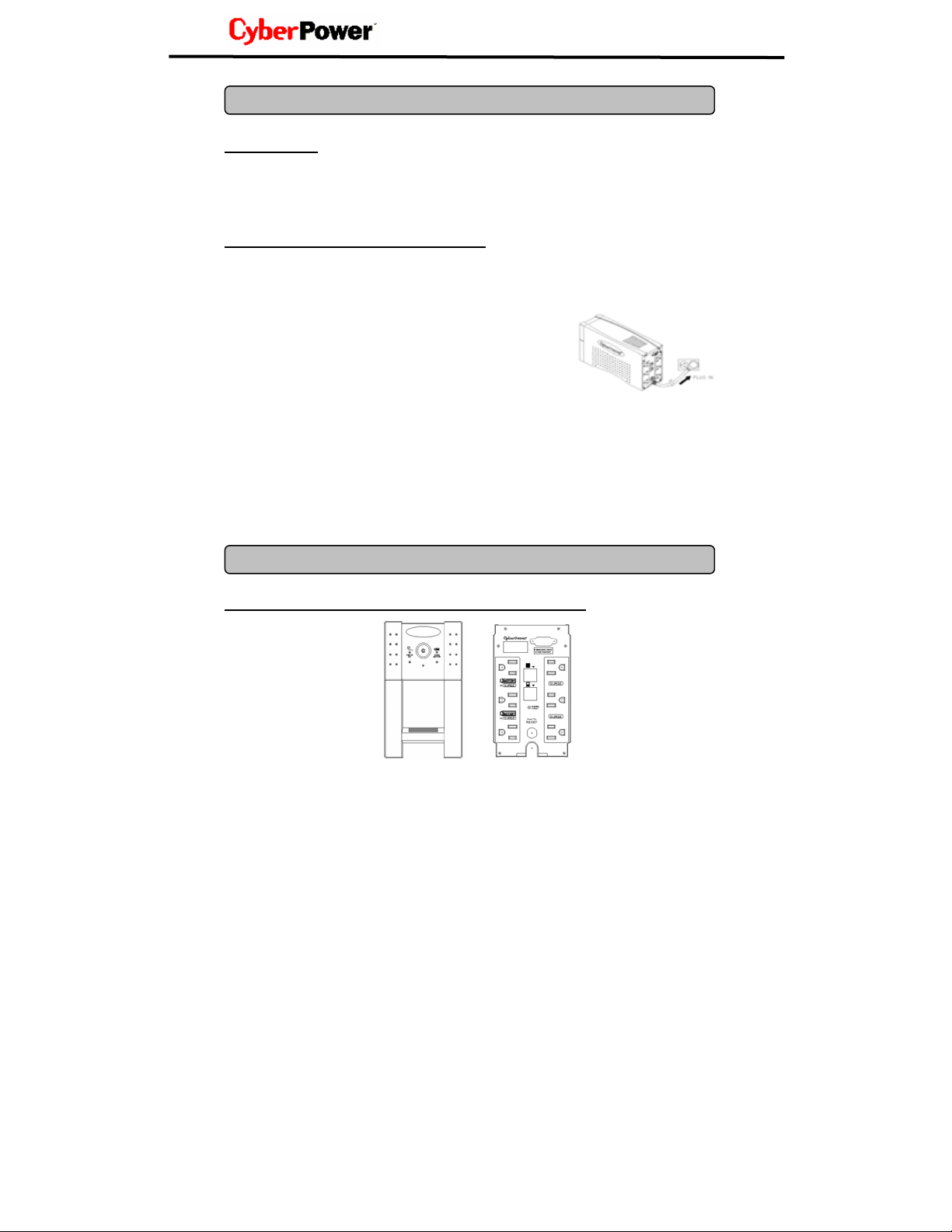
2. Connect your UPS power cord into a two-pole, three-wire
grounding receptacle only. Please avoid using extension
cords and adapter plugs. (To maintain optimal battery
charge, leave the UPS plugged in at all times.)
3. Press the UPS power button to turn it on. The “Power On” indicator will be illuminated
Green.
4. Install your optional software and accessories. To use the software, simply connect the
enclosed serial interface cable to the serial port on the UPS and an open serial port on
the computer.
FRONT PANEL AND REAR PANEL DESCRIPTION
BASIC OPERA TIO N
2
Page 5
Guaranteed Uninterruptible Power System
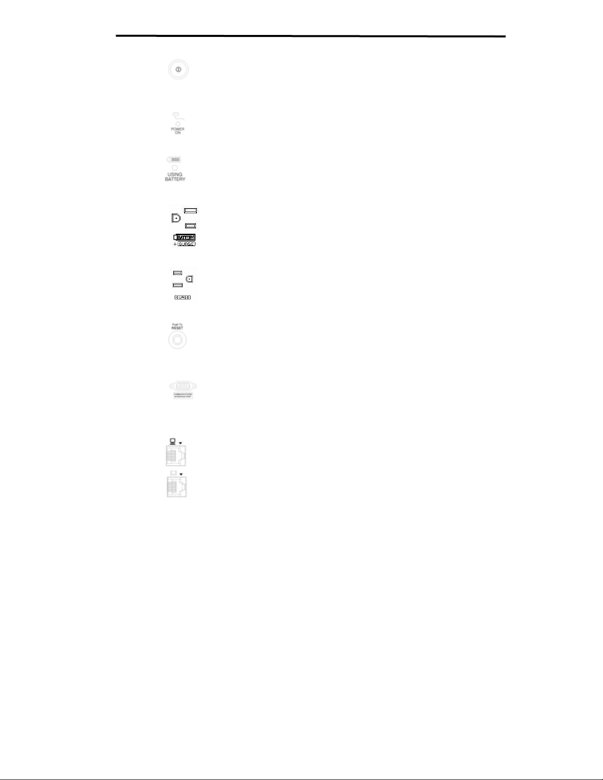
◆ Power Button
Press the power button to turn the UPS ON or OFF
◆ Power On Indicator
This LED is illuminated when the utility condition is normal and the UPS
outlets are providing “clean power”, free of surges and spikes.
◆ Using Battery Indicator
This illuminates during utility failure, indicating that the battery is
supplying power to the battery-power supplied outlets.
◆ Battery Backup and Surge Protection Outlets
Provides three battery powered and surge protected outlets for
connected equipment to insure temporary uninterrupted operation
during a power failure and protection against surges and spikes.
◆ Surge Protection Outlets
Provides three surge protected only outlets for connected equipment.
◆
Circuit Breaker Reset for Overload Protection
Resetable circuit breakers provide optimal overload protection. When
an overload occurs, the circuit breaker will pop and the UPS will switch
to battery back-up mode. Unplug at least one item from the UPS and
press the circuit breaker in to reset it.
◆ Serial Port to PC
This port allows connection and communication from the DB-9 serial or
USB port on the computer to the UPS unit. The UPS communicates
its status to the PowerPanel Plus™ software. This interface is also
compatible with the UPS service provided by Windows NT, Windows
2000 and Windows XP.
◆ Network Protection Ports (RJ45/RJ11)
These ports protect standard network cables and telephone cables.
3
UP625/ UP825
Page 6

BATTERY REPLACEMENT AND STORAGE
Contact your dealer or call the number in this manual for information on battery replacement.
The order numbers for the battery are as follows:
BA-UP625 for UP625
BA-UP825 for UP825
CAUTION! Read and follow the IMPORTANT SAFETY INSTRUCTIONS before servicing
the battery. Service the battery under the supervision of personnel knowledgeable of
batteries and their precautions. Keep unauthorized personnel away from batteries.
CAUTION! Use only the specified type of battery. See your dealer for replacement
batteries.
CAUTION! The battery may present the risk of electrical shock. Do not dispose of batteries
in a fire, as it may explode. Follow all local ordinances regarding proper disposal of
batteries.
CAUTION! Do not open or mutilate the batteries. Release electrolyte is harmful to the skin
and eyes and may be toxic.
CAUTION! A battery can present a high risk of short circuit current and electrical shock.
Take the following precautions before replacing the battery:
1. Remove all watches, rings or other metal objects.
2. Only use tools with insulated handles.
3. DO NOT lay tools or other metal parts on top of battery or any battery terminals.
4. Wear rubber gloves and boots.
5. Determine if the battery is inadvertently grounded. If inadvertently grounded, remove
source of ground. CONTACT WITH A GROUNDED BATTERY CAN RESULT IN
ELECTRICAL SHOCK! The likelihood of such shock will be reduced if such grounds
are removed during installation and maintenance (applicable to a UPS and a remote
battery supply not having a grounded circuit).
BATTERY REPLACEMENT PROCEDURE :
1. Turn off and unplug all connected equipment.
2. Turn the UPS off and unplug it from the AC power source.
3. Turn the UPS upside down.
4. Remove the 4 retaining screws and remove the cover.
4
Page 7

Guaranteed Uninterruptible Power System
5. Remove the battery from the compartment.
6. Disconnect the battery wires from the battery.
7. Install the replacement battery by connecting the red wire to
the positive (+) terminal of the battery and connecting the
black wire to the negative (-) terminal of the battery.
8. Slide the battery back into the compartment.
9. Replace the cover and the 4 retaining screws.
10. Recharge the unit for 4 – 8 hours to ensure the UPS
performs expected runtime.
REMINDER: Batteries are considered HAZARDOUS WASTE and must be disposed of
properly. Contact your local government for more information about proper disposal and
recycling of batteries.
UP625/ UP825
STORAGE:
First turn off your UPS and disconnect its power cord from the wall outlet. Disconnect all
cables connected to the UPS to avoid battery drain. To store your UPS for an extended
period, cover it and store with the battery fully charged. Recharge the battery every three
months to insure battery life. If the battery remains uncharged for an extended period of
time, it may suffer permanent loss of capacity.
5
Page 8

TROUBLESHOOTING
Problem Possible Cause Solution
The UPS does not
perform expected
runtime.
The UPS will not turn on.
Batteries are not fully
charged.
Battery’s capacity
diminishes over time and
use.
The on/off switch is
designed to prevent damage
by rapidly turning it off and
on.
The unit is not connected to
an AC outlet.
Recharge the battery by leaving the
UPS plugged in.
Contact CyberPower Systems at
tech@cyberpowersystems.com
Turn the UPS off. Wait 10 seconds
and then turn the UPS on.
The unit must be connected to a
110/120v 60Hz outlet.
Outlets do not provide
power to equipment
The battery is worn out. Contact CyberPower Systems at
Mechanical problem. Contact CyberPower Systems at
Circuit breaker is tripped
due to overload
Batteries are discharged Allow the unit to recharge for at least
Unit has been damaged by
a surge or spike.
tech@cyberpowersystems.com
tech@cyberpowersystems.com
Turn the UPS off and unplug at least
one piece of equipment. Wait 10
seconds, reset the circuit breaker
and then turn the UPS on.
4 hours.
Contact CyberPower Systems at
tech@cyberpowersystems.com
6
Page 9

Guaranteed Uninterruptible Power System
TECHNICAL SPECIFICATIONS
UP625/ UP825
Model UP625 UP825
Capacity (VA) 625VA 825VA
Capacity (Watts) 340W 450W
Input
Input Voltage Range 100Vac – 140Vac
Frequency Range 57 – 63 Hz
Output
On Battery Output Voltage Simulated Sine Wave at 120Vac +/- 5%
On Battery Output Frequency 60 Hz +/- 1%
Transfer Time (Typical) 4ms
Overload Protection
Surge Protection and Filtering
Lightning / Surge Protection Yes
Internet Ready (DSL / Phone /
FAX / Modem Protection)
Physical
Total # of UPS Receptacles 6
Maximum Dimensions 28.3cm*9.1cm*16.4cm
Weight 6.4kg 7.5kg
Battery
Sealed Maintenance Free Lead
Acid Battery
User Replaceable Yes, Hot Swappable Battery Pack
Typical Recharge Time 8 Hours
Warning Diagnostics
Indicators
Audible Alarms On Battery, Low Battery, Overload
Communication
Power Panel Plus Software Windows 95/98/ME/NT/2000/XP
Management
Self-Test Yes
Auto-Charger Yes
Auto-Restart
USB Optional
On Utility: Circuit Breaker, On Battery: Internal Current Limiting
RJ11/RJ45 (One In/One Out)
12V / 7AHx1 12V / 9AHx1
Power On, Using Battery, Wiring Fault
Yes
7
Page 10

DEFINITIONS FOR ILLUMINATED LED INDICATORS
Power
On
On Off Off Set Off
Off On/Off On Set
Off On/Off On Set
Off Off On Up
Off On/Off On/Off Set
On/Off On On/Off Set/Up None
Wiring
Fault
Using
Battery
Circuit
Breaker
Alarm
Two
Beeps
Rapid
Beeps
Two
beeps
or
rapid
beeps
Long
Beep
Normal
Utility Failure- The UPS is providing battery power
to the Battery-Power Supplied outlets.
Utility Failure- The UPS is providing battery power.
The rapid beeps indicate the battery will run out of
charge within a few minutes.
Overload- Occurs in the Full-time Surge Protection
Outlets. Turn the UPS off and unplug at least one
piece of equipment from the UPS. Wait 5
seconds, reset the circuit breaker and turn the
UPS on.
Overload- Occurs in the Battery-power Supplied
Outlets. Turn the UPS off and unplug at least one
piece of equipment from the UPS. Wait 5
seconds, reset the circuit breaker and turn the
UPS on.
Electrical Wiring Fault- This indicates a wiring a
problem such as a bad ground, missed ground or
reversed wiring within the AC outlet. User is
advised to disconnect all electrical equipment from
the outlet and have the outlet checked by an
electrician.
Condition
LIMITED WARRANTY AND POWER CONTROL GUARANTEE
In purchasing UP625/ UP825 in the United States or Canada, the original end user receives
a Limited Warranty and CyberPower's Power Control Guarantee from CyberPower Systems
(USA), Inc. (for ease of reading, referred to as "CyberPower"). The Limited Warranty and
the Power Control Guarantee are intended to be the initial end-user's exclusive rights and
remedies. The Limited Warranty and the Power Control Guarantee are separate, all though
they are related.
Limited Warranty. The original end user (referred to as the "Initial Customer") receives an
express limited warranty for the UP625 / UP 825 (referred to as the "Limited Warranty"),
purchased from CyberPower (referred to as the "Product"). The Limited Warranty is for the
Product itself. The terms of the Limited Warranty are explained below.
Power Control Guarantee. CyberPower also provides the Initial Customer with protection
in the event that the Product is not free from defects in materials and workmanship, and
certain equipment connected to the Product is damaged (the "Power Control Guarantee").
The Power Control Guarantee protects the Initial Customer for damage to equipment
plugged into the Product. The terms of the Power Control Guarantee are explained below.
The Limited Warranty and the Power Control Guarantee are subject to the terms set forth
8
Page 11

Guaranteed Uninterruptible Power System
UP625/ UP825
below. Additionally, State or Provincial law may adjust the terms of the Limited Warranty or
the Power Control Guarantee or the State or Province may impose additional obligations, or
additional "implied warranties." To the extent necessary to comply with those laws, the
terms of the Limited Warranty and the Power Control Guarantee should be read to adjust to
those requirements only to the extent necessary to comply with such local law.
If you are an Initial Customer, you are asked to read the following terms and conditions
carefully before using the Product. By using the Product you consent to be bound by and
become a party to the Limited Warranty and Power Control Guarantee. If you do not agree
to the terms and conditions of the Limited Warranty and Power Control Guarantee, you
should return the Product for a full refund prior to using it.
REGISTRATION
CyberPower requests that you complete and return the Warranty Registration Card
enclosed with the Product or register the Product at its website
(www.cyberpowersystems.com) to establish that you are the original end-user consumer
purchaser of the Product, and therefore entitled coverage under the Limited Warranty and
the Power Control Guarantee. (Registration is not required for Limited Warranty coverage,
but note if you do not complete a registration card you will be required to provide proof of
purchase, as described below, to have the benefits of this Limited Warranty.)
LIMITED WARRANTY
CyberPower warrants to you, the Initial Purchaser, that the Product will be free from defects
in material and workmanship for three years from the date of original purchase, subject to
the terms of this Limited Warranty.
To be covered you must still be the owner of the Product at the time of the failure that results
in the claim made under this Limited Warranty.
Your exclusive remedy and CyberPower's' sole obligations are as follows for the Product:
If (a) the CyberPower Product you purchased and still own is defective in material or
workmanship under this Limited Warranty or any applicable warranty imposed by law, and
(b) all Limited Warranty requirements have been met, CyberPower will repair or replace the
Product if it proves to be defective in material or workmanship during the Warranty Period.
To make a Limited Warranty claim on a Product, you must do the following:
1. Complete and return the CyberPower Warranty Registration Card, or provide
reasonable proof of purchase (for example, a sales receipt) that establishes you as the
Initial Customer (the original end-user consumer purchaser) of the Product and prove
that the Product was purchased within three (3) years of the event for which you want to
make a claim for warranty service.
2. Call CyberPower at (952) 403-9500, write to CyberPower at 5555 12th Ave. East,
Suite 110, Shakopee, MN 55379, or e-mail CyberPower at
tech@cyberpowersystems.com, within ten (10) days of the event for which you want to
make a claim for warranty service.
3. When you contact CyberPower, identify the Product, the Purchase Date, and request
Return Materials Authorization (RMA) information from CyberPower.
4. Pack and ship the Product to CyberPower as instructed in your RMA. Show the RMA
code on the shipping label or include it with the Product. You MUST prepay all
shipping costs and you are responsible for packaging and shipment.
Page 12

CyberPower will inspect and examine the Product within ten (10) days of receipt. If the
Product is not as warranted, CyberPower will repair or replace the Product and return it to
you at CyberPower's expense, or, if CyberPower is unable to or decides not to repair or
replace the Product (if defective) within a reasonable time, CyberPower will refund to you
the full purchase price you paid for the Product (purchase receipt showing price paid is
required).
9
If you are the Initial Purchaser and the Product is still covered by the Limited Warranty, the
Power Control Guarantee provides protection for damage to equipment connected to the
Product ("Connected Equipment"), subject to certain terms and limitations.
The Power Control Guarantee is not "first dollar" coverage. CyberPower's obligation is
reduced by any amounts that Initial Customer is entitled to recover from other sources
regarding the Connected Equipment, including insurance, other warranty, or extended
warranty coverage, whether or not the Initial Customer makes a claim for recovery,
including but not limited to a claim under any applicable insurance, other warranty, or
extended warranty.
The Power Control Guarantee is separate from the Limited Warranty, but they are related.
The Limited Warranty does not cover Connected Equipment, but as is explained below, to
be covered under the Power Control Guarantee, the Connected Equipment must have been
damaged due to a failure of the Product that is covered by the Limited Warranty. The
Connected Equipment must have been damaged due to a defect in materials or
workmanship of the Product, and the Product must still be covered by the Limited Warranty
and the Initial Customer has made a valid claim for the Product under the Limited Warranty.
In the event of damage to the Connected Equipment, your exclusive remedy, and
CyberPower's sole obligations, are as follows for Connected Equipment. If (a) the Product
purchased and owned by you is defective in material or workmanship under the Limited
Warranty or any applicable Implied Warranty; (b) the Limited Warranty requirements have
been met, and; (c) none of the limitations or exclusions on warranty coverage apply,
CyberPower will (as CyberPower elects, as permitted by law), repair, replace, or pay the
Agreed Damage Amount (defined below) for, the item(s) of your electronic equipment
directly and properly connected to the product (the "Connected Equipment") if that
Connected Equipment is (x) damaged by AC power line transients, spikes, or surges on
properly installed, grounded, and code-compliant 120 volt power lines in the United States
and Canada, or by transients, surges or spikes on standard telephone equipment lines, or
Base 10/100T Ethernet lines that are properly installed and connected (a "Power
Disturbance") and (y) is directly plugged into and properly connected to a CyberPower
Product in its original condition which is properly operated when a Power Disturbance
passes through the CyberPower Product and (y.1) exhausts the protection capacity of the
CyberPower Product or (y.2) damages the CyberPower Product. This provision sets out the
only liability of any character of CyberPower for direct, indirect, special, consequential,
and/or incidental damages under our Limited Warranty, applies only to Connected
Equipment, and all such Liability is limited to the Agreed Damage Amount.
To make a Warranty claim for damage to Connected Equipment under the Power Control
Guarantee, you must do the following:
1. Have completed and returned the CyberPower Warranty card or provide reasonable
proof of purchase, for example, a sales receipt that establishes you as the original
10
POWER CONTROL GUARANTEE
Page 13

Guaranteed Uninterruptible Power System
end-user consumer purchaser of the product.
2. Call CyberPower at (952) 403-9500, write to CyberPower at 5555 12th Ave East,
Suite 110, Shakopee, MN 55379, or e-mail CyberPower at
tech@cyberpowersystems.com within ten (10) days of the date of the event for which
you wish to make a claim for warranty service.
3. When you contact CyberPower, identify the Product, the Purchase Date, and the
item(s) of Connected Equipment. Have information on all applicable insurance or other
resources of recovery/payment that are available to the Initial Customer and the name of
the power utility supplier for the location of the connected equipment and Request a
Return Materials Authorization (RMA).
4. Pack and ship the product to CyberPower and, if requested, the item(s) of Connected
Equipment, a repair cost estimate for the damage to the Connected Equipment, and all
claim forms that CyberPower provides to you. Show the RMA number on the shipping
label or include it with the product. Initial Customer shall prepay all shipping costs
and is responsible for packaging and shipment.
CyberPower will inspect and examine the Product and the item(s) of Connected Equipment
(or at CyberPower's election, your written statement and repair cost estimate for those
item(s)). You must return the product for inspection.
If the Product is warranted under the Limited Warranty and the damage to Connected
Equipment is covered by the Power Control Guarantee, CyberPower will (in addition to
Limited Warranty remedies for the CyberPower Product itself) repair (or pay the costs of
repair) or replace the Connected Equipment or, at the option of CyberPower, as permitted
by law, pay to the Initial Customer the "Agreed Damage Amount" (up to the aggregate limits
stated below) for all item(s) of Initial Customer's Connected Equipment. The "Agreed
Damage Amount" for all items of Initial Customer's Connected Equipment shall be the
lesser of the amount determined under Clause (1) or (2) below, reduced by any amounts
described in
Clause (3) below:
1. The fair market value of the Connected Equipment as established by the lower of (a) the
average price the same or similar items are being sold for on E-bay, (b) the price list of
Orion
Blue Book on the date of occurrence (or if such price list is no longer published, a published
or announced price list reasonably selected by CyberPower), or (c) the lowest price the
same or similar items can be purchased for in the United States; or
2. The aggregate ceiling amount for all Connected Equipment as set forth below, minus;
3. The amount(s) of all payment you have or are entitled to receive from insurance, other
warranties, extended warranties, or from other sources or persons for the Connected
Equipment or damage to such equipment so that CyberPower’s maximum liability shall be
reduced to reflect all such other payments or sources of recovery:
CyberPower UP625 -$50,000.00 / UP825 -$75,000.00
4. If CyberPower replaces the connected equipment or pays to the Initial Customer the
Agreed Damage Amount, the Initial Customer shall transfer all item(s) to CyberPower
without warranty by the Initial Customer, but free of lien or other interest.
CONDITIONS COMMON TO THE LIMITED
UP625/ UP825
WARRANTY AND THE POWER CONTROL GUARANTEE
The Limited Warranty and the Power Control Guarantee are the only and the
exclusive express warranty of CyberPower with respect to the Product. This
exclusion of other express warranties applies to written and oral express warranties.
Page 14

Any Implied Warranty of Merchantability or for Fitness for a Particular Purpose, if applicable
to the Product, is limited in duration to the period of ownership by the Initial Customer. This
provision shall NOT create any Implied Warranty or Merchantability or of Fitness for a
Particular Purpose that would not otherwise apply to the Product. NOTE: Some States do
not allow limitations on how long an implied warranty lasts, so the above limitation
may not apply to you.
LIMITATION: THE LIMITED WARRANTY AND THE POWER CONTROL GUARANTEE
DO NOT COVER
The Limited Warranty and the Power Control Guarantee are intended to exclusive rights
and remedies and replace any other rights, to the extent allowed by law.
1. As to CyberPower products, the limited warranty does not cover or apply to: misuse,
modification, operation or storage outside environmental limits for the Products, in transit,
in shipment, or in storage, damage or deterioration, improper operation or maintenance,
or use with items or equipment not designed or intended for use with the product.
2. As to Connected Equipment, the Power Control Guarantee covers only damage
within the specific terms of the Power Control Guarantee to Connected Equipment (and
only up to the applicable aggregate ceiling amount). The Power Control Guarantee does
not cover damage to Connected Equipment or apply if the product has been operated in
a failure mode or not in compliance with CyberPower operating instructions and
manuals, or if the Connected Equipment has been operated in a failure mode or not in
compliance with the instructions and manuals of its manufacturer/vendor.
The Limited Warranty and the Power Control Guarantee Do Not Apply Unless The
Initial Customer:
1. Has properly connected the Product and the Connected Equipment to properly wired
and grounded outlets (including compliance with electrical and safety codes of the most
current electrical code (ANS/NFPA 70), without the use of any adapters, extension cords
of other connectors.
2. Has provided a suitable and proper environment for use and installation of the
Product and Connected Equipment.
3. Has properly installed and operated the CyberPower Product and Connected
equipment.
CyberPower Does Not Cover or Undertake Any Liability in Any Event for Any of the
Following:
1. Loss of or damage to data, records, or software or the restoration of data or records,
or the reinstallation of software.
2. Damage from causes other than AC Power Line Transients, spikes, or surges on
properly installed, grounded and code-compliant 120 volt power lines in the United
States and Canada; transients, surges or spikes on standard telephone land lines, PBX
telephone equipment lines or Base 10T Ethernet lines, when properly installed and
connected. (This exclusion applies, for example, to fluctuations in data transmission or
reception, by CATV or Therefore transmission or fluctuations, or by transients in such
transmission.
3. Damage from any circumstance described as excluded above with respect to the
product.
4. Damages from fire, flood, wind, rain, rising water, leakage or breakage of plumbing,
abuse, misuse or alteration of either the product or the Connected Equipment.
11
Page 15

Guaranteed Uninterruptible Power System
UP625/ UP825
Exclusion of Consequential and Other Damages.
The sole and exclusive remedies of the Initial Customer are those provided by the Limited
Warranty and Power Control Guarantee. CyberPower excludes any liability for personal
injury under the Limited Warranty and Power Control Guarantee. CyberPower excludes any
liability for direct, indirect, special, incidental or consequential damages, whether for
damage to or loss of property, loss of profits, business interruption, loss of information or
data, EXCEPT FOR (AND ONLY FOR) the specific limited agreement of CYBERPOWER to
provide certain warranty benefits regarding "Connected Equipment" under the
"CYBERPOWER Power Control Guarantee". NOTE: Some States or Provinces do not allow
the exclusion or limitation of incidental or consequential damages, so the above limitation
may not apply to you.
DO NOT USE FOR MEDICAL OR LIFE SUPPORT EQUIPMENT OR OTHER HIGH RISK
ACTIVITIES.
CyberPower does not sell the Products for use in high-risk activities. The Product is not
designed or intended for use in hazardous environments requiring fail-safe performance,
including the operation of nuclear facilities, aircraft navigation or communication systems,
air traffic control, weapons systems, life support or medical applications or for use in any
circumstance in which the failure of the Product could lead directly to death, personal injury,
or severe physical or property damage, or that would affect operation or safety of any
medical or life support device (collectively, "High Risk Activities"). CyberPower expressly
disclaims any express or implied warranty of fitness for High Risk Activities.
CyberPower does not authorize use of any of its products use in any High Risk Activities.
ANY SUCH USE IS IMPROPER AND IS A MISUSE OF CYBERPOWER PRODUCTS.
The Limited Warranty and the Power Control Guarantee are governed by the laws of the
United States and the S t ate of Minnesot a, without reference to conflict of law principles. The
application of the United Nations Convention of Contracts for the International Sale of
Goods is expressly excluded.
Contact Information: The address for CyberPower Systems (USA), Inc. is 5555 12th Ave
East, Suite 110, Shakopee, MN 55379 and its phone number is (952) 403-9500.
CyberPower is the warrantor under this Limited Warranty. You may also contact
CyberPower on the Internet at www.cyberpowersystems.com.
12
Page 16

13
 Loading...