

CyberPower OR600ELCDRM1U User Manual
OR600ELCDRM1U
User’s Manual
K01-0000232-00

IMPORTANT SAFETY INSTRUCTIONS
This manual contains important instructions that should be followed during installation and
maintenance of the UPS and batteries. Please read and follow all instructions carefully during
installation and operation of the unit. Read this manual thoroughly before attempting to
unpack, install, or operate.
CAUTION! The UPS must be connected to a grounded AC power outlet with fuse or circuit
breaker protection. DO NOT plug the UPS into an outlet that is not grounded. If you need to
de-energize this equipment, turn off and unplug the UPS.
CAUTION! DO NOT USE FOR MEDICAL OR LIFE SUPPORT EQUIPMENT! CyberPower
Systems does not sell products for life support or medical applications. DO NOT use in any
circumstance that would affect the operation or safety of any life support equipment, with any
medical applications, or patient care.
CAUTION! The battery can energize hazardous live parts inside even when the AC input
power is disconnected.
CAUTION! To prevent the risk of fire or electric shock, install in a temperature and humidity
controlled indoor area, free of conductive contaminants. (Please see specifications for
acceptable temperature and humidity range).
CAUTION! To reduce the risk of electric shock, do not remove the cover, except to service
the battery. There are no user serviceable parts inside, except for the battery.
CAUTION! To avoid electrical shock, turn off the unit and unplug it from the AC power source
before servicing the battery or installing a computer component.
CAUTION! DO NOT USE WITH OR NEAR AQUARIUMS! To reduce the risk of fire, do not
use with or near aquariums. Condensation from the aquarium can come in contact with metal
electrical contacts and cause the machine to short out.
INSTALLING YOUR UPS SYSTEM
UNPACKING
The box should contain the following:
(1) PowerPanel® Business Edition software (CD) x1; (2) USB cable (A+B type) x1; (3) Telephone
communication cable x1; (4) RS232 (DB9) cable x1; (5) Power cord x4; (6) user manual x1; (7) UPS
unit x1.
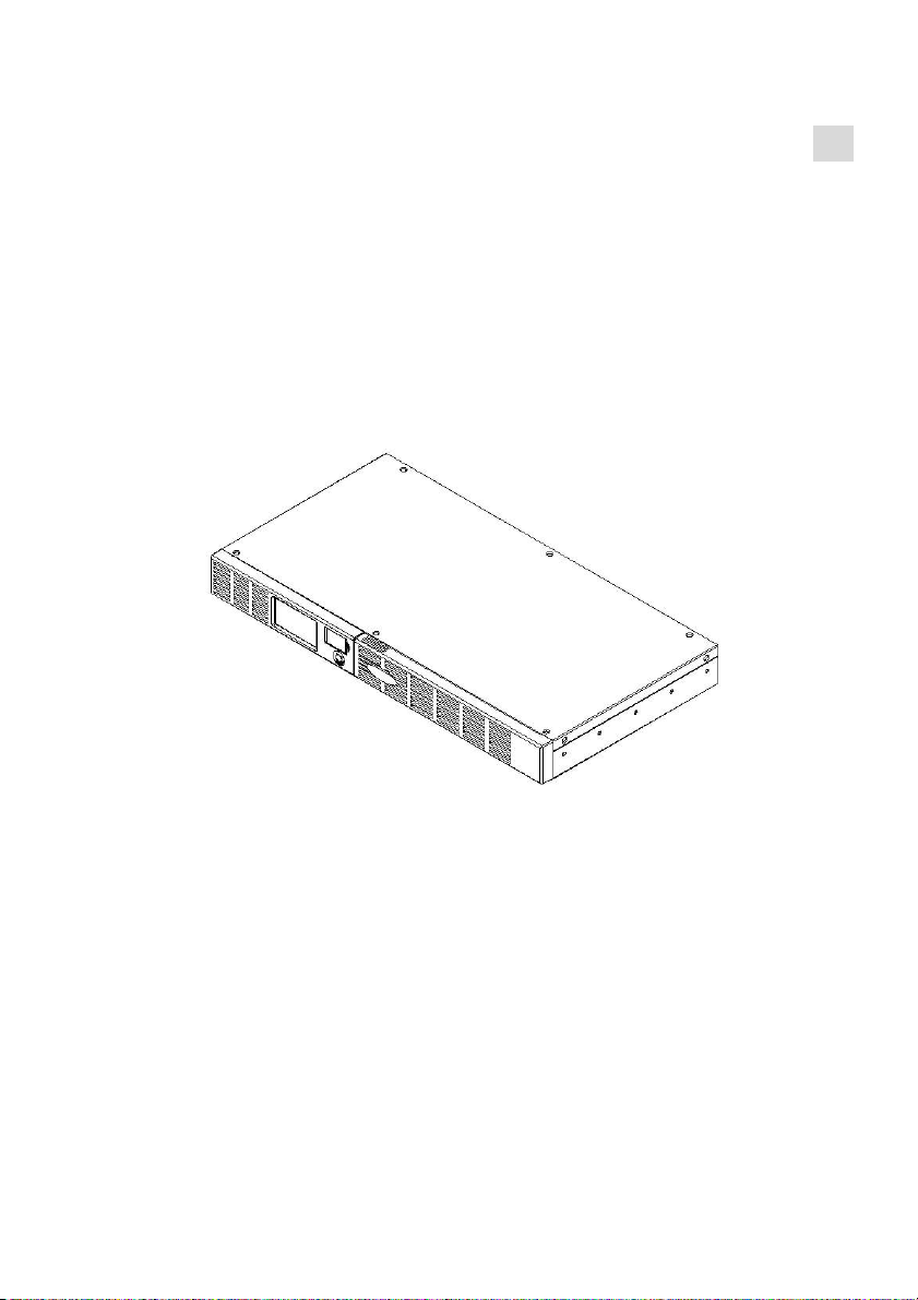
OVERVIEW
The OR600ELCDRM1U provides automatic voltage regulation for inconsistent utility power. The
OR600ELCDRM1U features 1030 Joules of surge protection, and provides battery backup during
power outages. The OR600ELCDRM1U ensures consistent power to your computer system and its
included software will automatically save your open files and shutdown your computer
system during a utility power loss.
HOW TO DETERMINE THE POWER REQUIREMENTS OF YOUR
EQUIPMENT
1.Make sure that the total Volt-Amp (VA) requirements of your computer, monitor, and
peripheral equipment does not exceed 600VA.
2.Ensure that the equipment plugged into the battery power-supplied/surge outlets does
not exceed the UPS unit's rated capacity (600VA/360W for OR600ELCDRM1U). If the rated unit
capacities are exceeded, an overload condition may occur and cause the UPS unit to shut down and
2
the circuit breaker to trip.
BASIC OPERATION
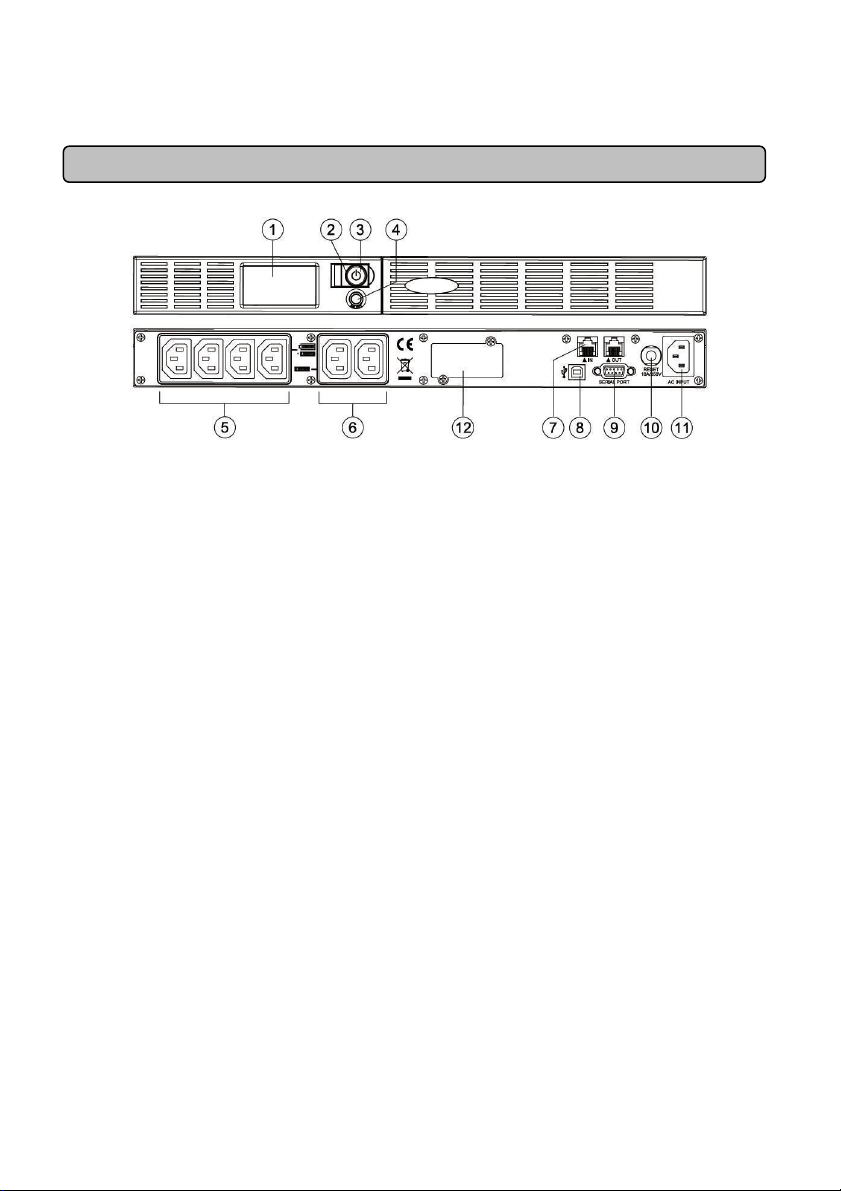
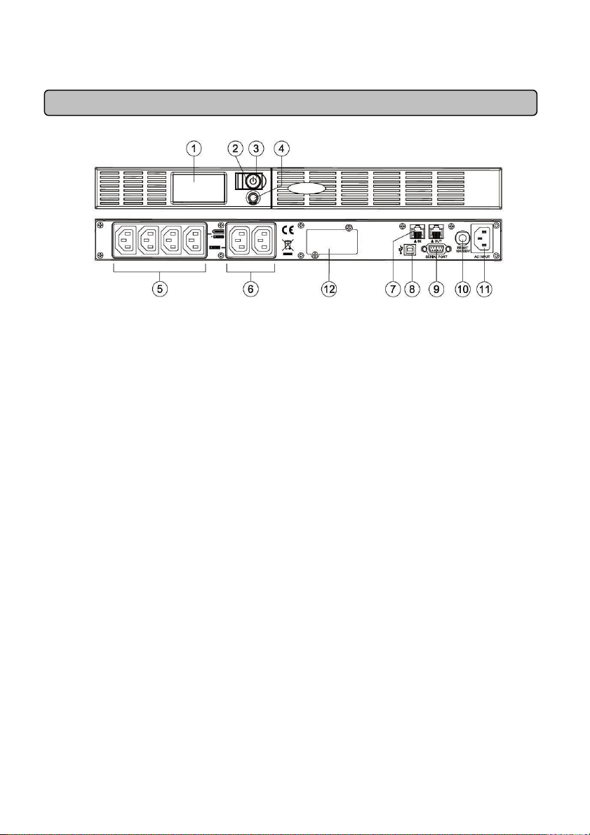
DESCRIPTION
1. LCD Module Display
High resolution and intelligent LCD display shows all the UPS information with icons and
messages. For more information please check the “Definitions for Illuminated LCD Indicators”
section.
2. Power On Indicator
It illuminates when the UPS outlets are providing power, free of surges and spikes.
3. Power Switch
Used as the master on/off switch for equipment connected to the battery power supplied outlets.
4. LCD Display Toggle/Selected Switch
The switch can be used to select the LCD display contents including Input Voltage, Output Voltage
and Estimated Run Time.
5. Battery and Surge Protected Outlets
The unit has four battery powered/surge protected outlets for connected equipment and ensures
temporary uninterrupted operation of your equipment during a power failure.
6. Full-Time Surge Protection Outlets
The unit has two always on surge suppression outlets.
7. Communication Protection Ports
Communication protection ports will protect any standard modem, fax, telephone line, broadband
network or Ethernet connection.
8. USB Port to PC
The USB port allow communication from the UPS to the computer. The UPS communicates its
status to the PowerPanel® Business Edition software when connected with a USB port.
9. Serial Port to PC
The port allows connection and communications from the DB-9 serial on the computer to the UPS
unit.
10. Circuit Breaker
Located on the side of the UPS, the circuit breaker serves to provide overload and fault protection.
11. AC Input
Connect the AC Power cord to a properly wired and grounded outlet.
12. Expansion Port
Allows users to add the optional SNMP card.
3

Hardware Installation Guide
1. Your new UPS may be used immediately upon receipt. However, recharging the battery for
at least 8 hours is recommended to ensure that the battery's maximum charge capacity
is achieved. Charge loss may occur during shipping and storage. To recharge the battery,
simply leave the unit plugged into an AC outlet. The unit will charge in both the on and off
position.
2. With the UPS unit off and unplugged, connect the computer, monitor, and any externally
powered data storage device (Zip drive, Jazz drive, Tape drive, etc. into the battery power
supplied outlets. DO NOT plug a laser printer, copier, space heater, vacuum, paper
shredder or other large electrical device into the UPS. The power demands of these
devices will overload and possibly damage the unit.
3. To protect a fax, telephone, modem line or network cable, connect a telephone cable or
network cable from the wall jack outlet to the IN jack of the UPS. Then connect a telephone
cable or network cable from the OUT jack on the UPS to the modem, computer, telephone,
fax machine, or network device.
4. Plug the UPS into a 2 pole, 3 wire grounded receptacle (wall outlet). Make sure the wall
branch outlet is protected by a fuse or circuit breaker and does not service equipment with
large electrical demands (e.g. air conditioner, refrigerator, copier, etc. Avoid using
extension cords. If used, the extension cord must be grounded and rated for 15 amps.
5. Depress the power switch to turn the unit on. The power on indicator light will illuminate
and the unit will "beep".
6. If an overload is detected, an audible alarm will sound and the unit will emit one long beep.
To correct this, turn the UPS off and unplug at least one piece of equipment from the
battery power supplied outlets. Wait 10 seconds. Make sure the circuit breaker is
depressed and then turn the UPS on.
7. To maintain optimal battery charge, leave the UPS plugged into an AC outlet at all times.
8. To store your UPS for an extended period, cover it and store with the battery fully
charged. Recharge the battery every three months to ensure battery life.
CYBERPOWER GREENPOWER UPS TECHNOLOGY
CyberPower’s Green Commitment
CyberPower is dedicated to the development of green products, and has adopted
Green practices throughout its business, including: membership in Climate Savers
Computing Initiative (CSCI), accordance with the Restriction on Hazardous
Substances (RoHS), Waste Electrical and Electronic Equipment (WEEE) protocols,
as well as ISO 14001 and IECQ QC080000. CyberPower pledges to provide the
advanced energy solution for the environment and become a leading eco-friendly
organization in the UPS industry.
Reduce Energy Cost with GreenPower UPSTM Technology
CyberPower’s goal is not only to provide eco-friendly products but also to bring the best value for
consumers. The advanced energy-saving design improves the operating efficiency and eliminates
waste energy consumption. As a result, consumers will enjoy significant energy cost savings with the
4

adoption of GreenPower UPSTM technology.
BATTERY REPLACEMENT
CAUTION! Read and follow the IMPORTANT SAFETY INSTRUCTIONS before servicing the
battery. Service the battery under the supervision of personnel knowledgeable of
batteries and their precautions.
CAUTION! Use only the specified type of battery. See your dealer for replacement batteries.
CAUTION! The battery may present the risk of electrical shock. Do not dispose of batteries in
a fire, as they may explode. Follow all local ordinances regarding proper disposal of batteries.
CAUTION! Do not open or mutilate the batteries. Released electrolyte is harmful to the skin
and eyes and may be toxic.
CAUTION! A battery can present a high risk of short circuit current and electrical shock. Take
the following precautions before replacing the battery:
1. Remove all watches, rings or other metal objects.
2. Only use tools with insulated handles.
3. DO NOT lay tools or other metal parts on top of battery or any battery terminals.
4. Wear rubber gloves and boots.
5. Determine if the battery is inadvertently grounded. If inadvertently grounded, remove source
of ground. CONTACT WITH A GROUNDED BATTERY CAN RESULT IN ELECTRICAL
SHOCK! The likelihood of such shock will be reduced if such grounds are removed during
installation and maintenance (applicable to a UPS and a remote battery supply not having a
grounded circuit)
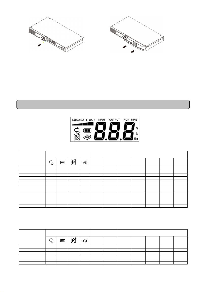
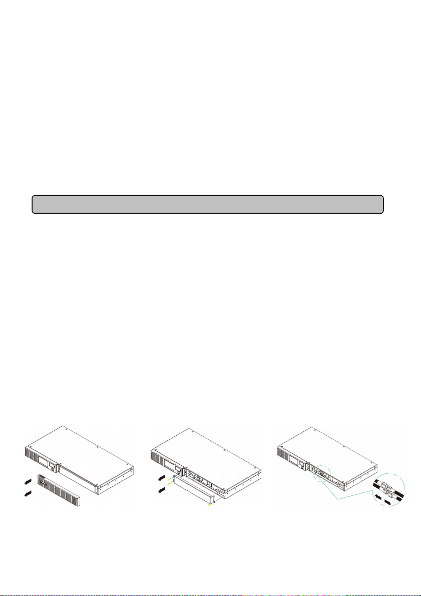
BATTERY REPLACEMENT PROCEDURE:
1. Remove the right-side of the
faceplate.
2. Remove the three retaining screws
on the cable protection cover then
remove the cover faceplate.
3. Disconnect the black and red cables.
5
%
Load
%
Batt.
Initial V X -- X V X V
1st V X -- X V X V
2nd V X -- X V X V
3rd V X -- X X V V
4th V X -- X V X V
5th(Return)
V X -- X V X V
Press >3sec
(Sound Di
s
able)
(Overload)
V X -- V -- -- -- -- -- -- --
%
Load
%
Batt.
Initial X V -- X X V V
1st X V -- X X V V
2nd X V -- X V X V
3rd X V -- X X V V
4th X V -- X X V V
5th(Return)
X V -- X X V V
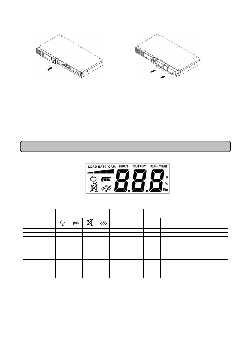
4. Remove the retaining screw of the
cable connectors.
REMINDER: Batteries are consider HAZARDOUS WASTE and must be disposed of properly. Almost
any retailer that sells lead-acid batteries collects used batteries for recycling, as required by most state
laws.
5. Replace the new battery pack. Assemble the
screws, cover, cable and front panel in the reverse
sequence of above steps. Recharge the unit for 4-8
hours to ensure the UPS performs expected runtime.
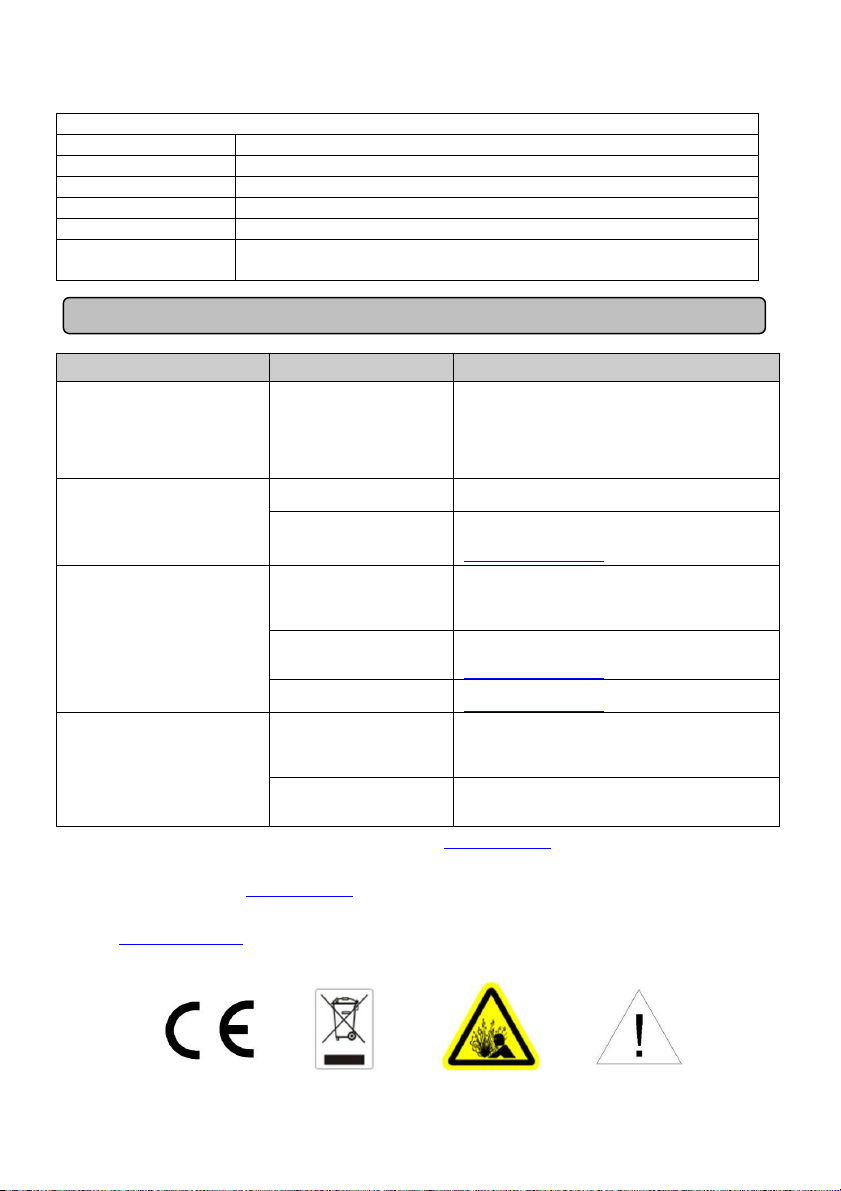
DEFINITIONS FOR ILLUMINATED LCD INDICATORS
LCD Indication
Line Mode
Select SW
Press
UPS Status Display Capacity Display
Load
Battery
Cap.
Cap.
Input
Voltage
Digital Value Display
Output
Voltage
Run
Time
of
of
V X V X -- -- -- -- -- -- --
Press >3sec
again
(Sound Enable)
“V” : Illuminated, “X” : Not Illuminated, “--“ : Either
V X X X -- -- -- -- -- -- --
Battery Mode
UPS Status Display Capacity Display
Select SW
Press
Load
Cap.
6
Battery
Cap.
Input
Voltage
Digital Value Display
Output
Voltage
Run
Time
of
of

Press >3sec
(Sound Di
s
able)
X V V X -- -- -- -- -- -- --
(Overload)
X V -- V -- -- -- -- -- -- --
Press >3sec
again
(Sound Enable)
“V” : Illuminated, “X” : Not Illuminated, “--“ : Either
X V X X -- -- -- -- -- -- --
TECHNICAL SPECIFICATIONS
Model OR600ELCDRM1U
Capacity (VA) 600VA/360W
Input
Frequency Range 47Hz-63Hz (Auto Sensing)
AVR Function Yes
Output
On Battery Output
Voltage
On Battery Output
Frequency
Overload Protection On Utility: Circuit Breaker, On Battery: Internal Current Limiting
Surge Protection
Lightning / Surge
Protection
Network/ Phone/ Fax/
Modem Protection
Operating
Temperature
Physical
Total # of UPS outlets
Maximum
Dimensions(LxWxH)
Weight 8.1 kg
Battery
Sealed Maintenance
Free Lead Acid
Battery
Typical Recharge
Time
User Replaceable Yes
Status Indicators
Indicators Power On, Wiring Fault, LCD Display
Audible Alarms On Battery, Low Battery, Overload
Communication
PowerPanel®
Business Edition
Windows 7 / VISTA / XP / 2000, Server 2008 / 2003
Software
230Vac +/-10%
50/60Hz +/-1%
Yes
RJ11/RJ45 ( One In/ One Out )
+32°F to 104°F ( 0°C to 40°C )
6 ( Backup x 4 )
1U Rack 430x235x44mm
6V / 9Ah x2
8 hours
7
Management
Full-time surge protection
the unit.
Battery not fully
charged.
Recharge the battery by leaving the UPS
plugged in.
The on/off switch is
turning it off and on.
Contact CyberPower Systems about
support@cpsww.eu
Contact CyberPower Systems at
support@cpsww.eu
Connect the
serial/
USB cable to the
UPS
came with the unit.
The unit is not
battery power.
Shutdown your computer and turn the
UPS back on. This should res
et the unit.
Self -Test Yes
Auto-Charger Yes
Auto-Restart Yes
USB interface Yes
Dry Contact Yes
SNMP/HTTP
Networking
Option
TROUBLESHOOTING
Problem Possible Cause Solution
outlets stop providing
power to equipment.
Circuit breaker button is
projecting from the side of
The UPS does not perform
expected runtime.
The UPS will not turn on.
PowerPanel® Business
Edition is inactive.
Additional troubleshooting information can be found at www.cpsww.eu
Circuit breaker has
tripped due to an
overload.
Battery is slightly worn
out.
designed to prevent
damage by rapidly
The battery is worn
out.
Mechanical problem.
The serial/USB cable
is not connected.
providing
Turn the UPS off and unplug at least one
piece of equipment. Wait 10 seconds, reset
the circuit breaker by depressing the
button, and then turn the UPS on.
Contact CyberPower Systems about
replacement batteries at
support@cpsww.eu
Turn the UPS off. Wait 10 seconds and
then turn the UPS on.
replacement batteries at
unit and an open serial port on the back of
the computer. You must use the cable that
UPS off. Wait 10 seconds and turn the
For more information, visit www.cpsww.eu or contact
Cyber Power Systems, Inc.
E-MAIL: sales@cpsww.eu
All rights reserved. Reproduction without permission is prohibited.
8
FR
OR600ELCDRM1U
Manuel d’utilisation
9

AVERTISSEMENTS DE SECURITE IMPORTANTS
Ce manuel contient d’importantes instructions de sécurité. Veuillez lire et suivre scrupuleusement
toutes les instructions pendant l’installation et l'utilisation de l’appareil. Lisez ce manuel attentivement
avant de déballer, d’installer ou d'utiliser votre UPS (système d’alimentation sans coupure).
ATTENTION ! Pour éviter les risques d’incendie ou d’électrocution, installez l’UPS dans une pièce dont
la température et l’humidité sont contrôlées et qui est dépourvue de contaminants conducteurs
(Reportez-vous aux spécifications pour connaître les gammes de température et d’humidité
acceptables).
ATTENTION ! Pour réduire les risques d’électrocution, ne retirez pas le couvercle. L’appareil ne
comporte aucune pièce réparable par l’utilisateur.
ATTENTION ! Des pièces sous tension dangereuses à l’intérieur de l’appareil peuvent être alimentées
par la batterie même quand l’entrée de courant CA est débranchée.
ATTENTION ! L’UPS doit être relié à une prise de courant CA munie d’un fusible et d'un disjoncteur. Ne
le branchez pas dans une prise qui n’est pas mise à la terre. Si vous devez cesser l’alimentation de cet
appareil, éteignez-le puis débranchez-le.
ATTENTION ! Pour éviter les électrocutions, éteignez l’UPS et débranchez-le de la source de courant
CA avant d’installer un composant d’ordinateur.
NE PAS UTILISER POUR DES EQUIPEMENTS MEDICAUX ! Les systèmes CyberPower ne sont pas
destinés aux applications médicales. Ne pas utiliser dans des situations qui affecteraient le
fonctionnement et la sécurité d’équipements et d’applications médicales ou la survie du patient.
NE PAS UTILISER AVEC OU A PROXIMITE DES AQUARIUMS! Pour réduire les risques d’incendie
ou d’électrocution, n’utilisez pas l’UPS avec ou à proximité d’un aquarium. La condensation de
l’aquarium peut court-circuiter l’appareil.
INSTALLATION DE VOTRE SYSTEME UPS
DEBALLAGE
Inspectez l’UPS tout en consultant le bordereau d’expédition afin de vous assurer qu’aucune des
pièces suivantes ne manque:
(1) CD du logiciel PowerPanel® Business Edition x 1; (2) Câble USB x 1; (3) Câble pour téléphone x 1;
(4) Câble RS232 (DB9) x1; (5) Câbles d'utilisation x 4; (6) Mode d’emploi x 1; (7) Unité UPS x 1.
EXPOSE GENERAL
Le OR600ELCDRM1U fournit une régulation automatique de la tension pour le courant électrique
inconsistant. Le OR600ELCDRM1U intègre une protection parafoudre de 1030 Joules contre la
surtension, et alimente la batterie pendant les pannes de courant. Le OR600ELCDRM1U garantit
l’alimentation consistante de votre ordinateur et son logiciel inclus sauvegardera automatiquement vos
fichiers ouverts et éteindra le système de votre ordinateur pendant les pannes de courant.
COMMENT DETERMINER LES CONDITIONS ELECTRIQUES DE VOTRE UPS
1. Assurez-vous que le besoin total en Volt-ampère (VA) de votre ordinateur, du moniteur et
des équipements périphériques ne dépasse pas 600VA.
2. S'assurer que les équipements branchés sur les prises power-supplied/surge batterie ne dépasse
pas la capacité nominale de l'unité UPS (600VA/360W pour OR600ELCDRM1U). Si les capacités des
unités sont dépassées, une condition de surcharge peut survenir et causer l’arrêt de l’UPS et la
disjonction du disjoncteur.
10
OPERATIONS DE BASE
DESCRIPTION
1. Ecran numérique
L’écran numérique intelligent haute résolution affiche toutes les informations de l’UPS avec icônes
et messages. Pour de plus amples informations veuillez consulter la section “Définitions des
voyants allumés de l’écran numérique”.
2. Indicateur de fonctionnement
Il s’allume quand la qualité du réseau électrique est normal et que les prises de l’UPS fournissent
du courant, sans surtension ni pointe.
3. Bouton marche/arrêt
Sert de bouton marche/arrêt principal pour les appareils branchés aux prises ondulées.
4. Bouton poussoir /Interrupteur de sélection de l’écran numérique
L’interrupteur peut être utilisé pour sélectionner le contenu de l’affichage y compris la tension
d’entrée, la tension de sortie, et le temps de fonctionnement estimé.
5. Batteries et Prises protégées contre les surtensions
L’UPS possède 4 prises de sorties ondulées et protégées contre les surtensions pour garantir le
fonctionnement ininterrompu de votre appareil pendant une panne de courant.
6. Prises de sortie de protection permanente contre les surtensions (2 prises)
Fournit deux prises protégées contre les surtensions pour les équipements connectés.
7. Ports de protection de la communication
Les ports de protection de la communication protègeront toutes les lignes standard de modem, fax,
ou téléphone, les réseaux ADSL ou les connexions Ethernet.
8. Port USB vers PC
Ce port permet la connexion et la communication depuis le port USB de l’ordinateur vers
l’onduleur. L’onduleur communique son statut au logiciel PowerPanel® Business Edition.
9. Port série vers PC
Ce port permet la connexion et la communication à partir d’un port série DB-9 de l’ordinateur vers
l’unité UPS.
10. Disjoncteur
Situé à l'arrière de l'UPS, le disjoncteur assure une protection contre les surcharges.
11. Entrée AC
Connectez le câble d’alimentation pour alimenter l’onduleur en courant électrique.
12. Port d'extension
Permet à l'utilisateur d'ajouter la carte SNMP optionnelle.
11

GUIDE D’INSTALLATION DU MATERIEL
1. Vous pouvez utiliser votre nouvel UPS dès la réception. Cependant, il est recommandé de charger la
batterie pendant au moins 8 heures pour vous assurer qu'elle soit chargée au maximum. Une perte
de charge peut se produire pendant le transport et le stockage de l’appareil ; il devra donc être
branché à une prise murale. L’appareil se chargera aussi bien en position MARCHE (ON)
qu’ARRET (OFF).
2. Avec l'onduleur éteint et débranché, connectez votre ordinateur, moniteur, et tous les autres
périphériques nécessitant une protection par onduleur . Branchez les autres équipements
(imprimante, scanner, haut-parleurs) dans les prises uniquement protégées contre les surtensions.
NE PAS brancher une imprimante laser, destructeur de papier, de photocopieur, appareil de
chauffage, pompe de puisard ou tout autre appareil électrique ayant une consommation électrique
importante dans les prises ondulées. Les besoins en énergie de ces dispositifs pourraient
éventuellement endommager l'appareil.
3. Pour protéger un fax, un téléphone un modem , ou le câble réseau, branchez un câble téléphonique
ou un câble réseau de la prise murale à la prise IN de l'UPS. Ensuite, connectez un câble
téléphonique ou un câble réseau de la prise OUT sur l'onduleur vers le modem, ordinateur,
téléphone, télécopieur ou un périphérique réseau.
4. Branchez l’UPS dans une prise 2 pôles+ Terre (prise murale). Assurez-vous que la prise murale
soit protégée par un fusible ou un disjoncteur et ne desserve pas un appareil dont la demande en
courant est importante (ex. réfrigérateur, photocopieuse, etc.…). Évitez d'utiliser des rallonges.
5. Appuyez sur l'interrupteur pour allumer l'appareil. L’afficheur s’allume et émet un "bip".
6. Si une surcharge est détectée, une alarme audible retentira et l’UPS émettra un long bip. Pour
corriger cela, éteignez l’UPS et débranchez au moins un des appareils des prises ondulées .
Patientez 10 secondes. Assurez-vous que disjoncteur est enclanché puis rallumez l’UPS.
7. Afin que la charge de la batterie reste optimale, laissez l’UPS branché dans une prise CA en
permanence.
8. Pour stocker votre UPS pour une période prolongée, couvrez-le et rangez-le avec une batterie
entièrement chargée. Rechargez la batterie tous les trois mois afin d’optimiser la vie de la batterie.
TECHNOLOGIE UPS CYBERPOWER GREENPOWER
CyberPower, un fabricant au cœur des enjeux environnementaux de demain
Le développement de produits verts associé à une politique d’entreprise
respectueuse de l’environnement constitue une priorité pour CyberPower.
L’adhésion de CyberPower à des organisations exigeantes en la matière ainsi que
l’obtention de normes strictes en témoignent:
- L’appartenance au CSCI (Climate Savers Computing Initiative) pour la
préservation du climat.
- La conformité aux restrictions sur les substances dangereuses (RoHS)
- Le recyclage optimisé des équipements électriques et électroniques (protocole WEE- Waste
Electrical and Electronic Equipment) ou DEEE
- Les normes ISO 14001 et IECQ QC 080000
Quotidiennement, CyberPower s’engage à développer des solutions de protection électriques
performantes et écologiques, confortant ainsi sa position de fabricant majeur et éco-responsable sur le
12
marché de l’onduleur.
Sauvegarde de l’environnement et réduction de la facture d’électricité : le pari gagné de la
technologie UPS GreenPower
Offrir aux consommateurs des produits économiques, propres et de hautes performances fait partie du
développement permanent de CyberPower.
L’onduleur GreenPower bénéficie d’une conception évoluée qui contribue à renforcer significativement
son efficacité énergétique.
- Un système de recharge optimisé pour une recharge batterie plus efficace et de meilleure qualité.
- Technologie Haute Fréquence ou circuit de dérivation pour limiter la dissipation calorifique et la
perte d’énergie en fonctionnement.
Adopter la technologie de l’onduleur GreenPower, c’est faire le choix de la performance et de
l’économie d’énergie (facture d’électricité réduite) tout en contribuant à la protection de
l’environnement.
REMPLACEMENT DE LA BATTERIE
ATTENTION ! Lisez et suivez les IMPORTANTES INSTRUCTIONS DE SÉCURITÉ avant de toucher à
la batterie. Remplacez la batterie sous la supervision d’un personnel qualifié.
ATTENTION ! Utilisez uniquement le type de batterie spécifié. Consultez votre revendeur pour
remplacer les batteries.
ATTENTION ! La batterie peut être la source de risques d’électrocution. Ne jetez pas la batterie dans
un feu car elle peut exploser. Respectez les réglementations locales concernant l’élimination
appropriée des batteries. Presque tous les revendeurs de batteries au plomb peuvent collecter les
batteries usagées pour le recyclage, comme cela est requis par la loi de la plupart des états.
ATTENTION ! N’ouvrez pas ni n’altérez les batteries. L’électrolyte contenu dedans est nocif pour la
peau et les yeux et peut être toxique.
ATTENTION ! Une batterie peut présenter un risque élevé de court-circuit et d’électrocution. Prenez les
précautions suivantes avant de remplacer la batterie:
1. Retirez les montres, bagues ou autres objets métalliques.
2. Utilisez uniquement des outils avec des poignées isolantes.
3. Ne posez pas les outils ou des pièces en métal sur la batterie ou sur ses pôles.
4. Portez des gants et des bottes en caoutchouc.
5. Vérifiez que la batterie ne soit pas mise à la terre par inadvertance. Si elle est mise à la terre, retirez
la source de terre. LE CONTACT AVEC UNE BATTERIE MISE A LA TERRE PEUT ENTRAINER UNE
ELECTROCUTION !
POUR REMPLACER LA BATTERIE:
1. Retirer le droit-côté de la plaque
avant.
2. Retirer les trois vis de retenue du
couvercle de protection du câble puis
retirer la plaque avant de couverture.
3. Déconnecter les câbles noir et rouge.
13
e
sortie
Durée
foncti
%
charg
%
batteri
Initial V X -- X V X V
1er V X -- X V X V
2ème V X -- X V X V
3ème V X -- X X V V
4 ème V X -- X V X V
5 ème (Retour)
V X -- X V X V
Appui >3sec
(Son désactivé)
Nouvel appui
(Son activé)
(Surcharge)
V X -- V -- -- -- -- -- -- --
4. Retirer la vis de retenue des câbles
du connecteur.
5. Remplacer par le nouveau bloc batterie.
Assembler les vis, le couvercle, le câble et le
panneau avant dans l'ordre inverse des étapes
ci-dessus. Recharger l'unité pendant 4-8 heures pour
s'assurer que l'onduleur atteint l'autonomie prévue.
RAPPEL : Les batteries sont considérées comme des DECHETS DANGEREUX et doivent être
éliminées de la manière la plus appropriée.
DEFINITIONS DES VOYANTS DE L’ECRAN NUMERIQUE
Témoin LCD
Mode Ligne
Charge
Cap.
Affichage
capacité
Batterie
Cap.
Affichage valeur numérique
Tension
Tension
d’entré
de
de
de
Interrupteur
Sélection
Affichage état UPS
de
V X V X -- -- -- -- -- -- --
>3sec
“V” : Illuminé, “X” : Non illuminé, “--“ : L’un ou l’autre
V X X X -- -- -- -- -- -- --
Mode Batterie
14

Charge
e
sortie
Durée
foncti
%
charg
%
batteri
Initial X V -- X X V V
1er X V -- X X V V
2ème X V -- X V X V
3ème X V -- X X V V
4 ème X V -- X X V V
5 ème (Retour)
X V -- X X V V
Appui >3sec
(Son désactivé)
No
uvel appui
(Son activé)
(Surcharge)
X V -- V -- -- -- -- -- -- --
Cap.
Affichage
capacité
Batterie
Cap.
Affichage valeur numérique
Tension
Tension
d’entré
de
Interrupteur
Sélection
>3sec
“V” : Illuminé, “X” : Non illuminé, “--“ : L’un ou l’autre
Affichage état UPS
X V V X -- -- -- -- -- -- --
X V X X -- -- -- -- -- -- --
SPECIFICATIONS TECHNIQUES
Modèle OR600ELCDRM1U
Puissance (VA) 600VA/360W
Entrée
Fréquence d’entrée 47Hz-63Hz (Auto Sensing)
AVR Oui
Sortie
Tension de sortie en
mode batterie
Fréquence de sortie
en mode batterie
Protection contre les
surcharges
Mode secteur : Coupe circuit, Mode Batterie : Limiteur de courant
230Vac +/-10%
50/60Hz +/-1%
interne
Parasurtenseur
Lightning / Protection
parafoudre
Oui
Internet Ready
(Protection ADSL / Tél
RJ11/RJ45 (1 entrée / 1 sortie )
/ FAX / Modem)
Température de
fonctionnement
de 0°C à 40°C
Physique
Nb tTotal de prises en
sortie
Dimensions maximum
6 ( ondulées x 4 )
1U Rack 430x235x44mm
Poids (kg) 8.1 kg
Batterie
Batterie étanche à
l’acide de plomb, sans
6V / 9Ah x2
maintenance
Durée de charge 8 heures
15
de
de
de
 Loading...