

Page 1
USER’S MANUAL
PFC SINEWAVE SERIES
OR1000PFCRT2U/OR1500PFCRT2U/
OR2200PFCRT2U
K01-0000488-01
EN
Page 2

1 Copyright © 2016 CyberPower Systems, Inc.
This manual contains important instructions. Please read and follow all instructions carefully during
installation and operation of the unit. Read this manual thoroughly before attempting to unpack, install, or
operate the UPS.
CAUTION! To prevent the risk of fire or electric shock, install in a temperature and humidity controlled
indoor area free of conductive contaminants. (Please see specifications for acceptable temperature and
humidity range).
CAUTION! For pluggable equipment, the socket-outlet shall be installed near the equipment and shall
be easily accessible.
CAUTION! To reduce the risk of electric shock, do not remove the cover except to service the battery.
Ensure the input power is removed before servicing the batteries. There are no user serviceable parts
inside except for the battery.
CAUTION! Hazardous live parts inside can be energized by the battery even when the AC input power
is disconnected.
CAUTION! The UPS must be connected to an AC power outlet with fuse or circuit breaker protection.
Do not plug into an outlet that is not grounded. If you need to de-energize this equipment, turn off and
unplug the unit.
CAUTION! To avoid electric shock, turn off the unit and unplug it from the AC power source before
servicing the battery or installing a computer component.
CAUTION! To reduce the risk of fire, connect only to a circuit provided with 20 amperes maximum
branch circuit over current protection in accordance with the National Electric Code, ANSI/NFPA 70.
CAUTION! The UPS is suitable for use in a computer room as defined in the Standard for the Protection
of Electronic Computer/Data Processing Equipment, ANSI/NFPA 75.
CAUTION! The EPO function is provided in UPS. EPO remote switch which is Push-Back button is
installed computer room outside by a phone line and not connected any other equipment.
CAUTION! DO NOT USE FOR MEDICAL OR LIFE SUPPORT EQUIPMENT! Under no circumstances
this unit should be used for medical applications involving life support equipment and/or patient care.
CAUTION! DO NOT USE WITH OR NEAR AQUARIUMS! To reduce the risk of fire, do not use with or
near aquariums. Condensation from the aquarium can come in contact with metal electrical contacts and
cause the machine to short out.
CAUTION! DO NOT USE WITH LASER PRINTERS! The power demands of laser printers are too large
for a UPS.
CAUTION! DO NOT INSTALL THE UPS WHERE IT WOULD BE EXPOSED TO DIRECT SUNLIGHT
OR NEAR A STRONG HEAT SOURCE!
CAUTION! DO NOT BLOCK OFF VENTILATION OPENINGS AROUND THE HOUSING!
CAUTION! DO NOT CONNECT DOMESTIC APPLIANCES SUCH AS HAIR DRYERS TO UPS
OUTPUT SOCKETS.
IMPORTANT SAFETY INSTRUCTIONS
Page 3
Copyright © 2016 CyberPower Systems, Inc.
2
UNPACKING
The box should contain the following:
(a) UPS unit x1; (b) User manual x1; (c) USB A+B type cable x1; (d) Rackmount bracket x2; (e) Vertical
stand x2; (f) Warranty registration card x1
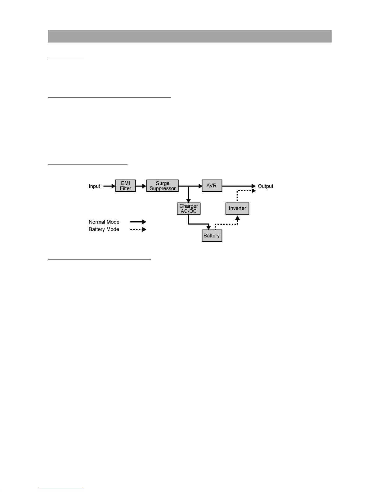
AUTOMATIC VOLTAGE REGULATOR(AVR)
The OR1000PFCRT2U/OR1500PFCRT2U/OR2200PFCRT2U can stabilize inconsistent utility power.
Incoming utility power fluctuations may be damaging to important data and hardware but Automatic
Voltage Regulation (AVR) helps protect the computer against experiencing dangerous voltage levels. AVR
automatically adjusts low or high voltages to keep equipment working at safe AC power levels (110/120V)
without switching to battery. Your equipment can operate normally even during the power problems such
as brownouts and blackouts. The unit’s powerful sealed lead-acid batteries will provide power only if the
incoming voltage drops below 90V or increases above 140V.
SYSTEM BLOCK DIAGRAM
HARDWARE INSTALLATION GUIDE
1. Battery charge loss may occur during shipping and storage. The first time the UPS is used, it is
strongly recommended to charge the batteries for at least 18 hours to ensure that the batteries are at
their maximum charge capacity. To recharge the batteries, simply plug the UPS into an AC outlet, the
batteries will charge whether the UPS is powered on or not.
2. With the UPS off and unplugged, connect your computer, monitor, and any externally powered data
storage device (Hard drive, Tape drive, etc.) into the outlets. DO NOT plug a laser printer, copier,
space heater, vacuum, paper shredder or other large electrical device into the UPS. The power
demands of these devices will overload and possibly damage the unit.
3. To protect a fax, telephone, modem line or network cable, connect the telephone or network cable
from the wall jack outlet to the jack marked “IN” on the UPS. Then, connect a telephone cable or
network cable from the jack marked “OUT” on the UPS to the modem, computer, telephone, fax
machine, or network device.
4. Plug the UPS into a 2 pole, 3 wire grounded receptacle (wall outlet). Make sure the wall branch outlet
is protected by a fuse or circuit breaker and does not service equipment with large electrical demands
(e.g. air conditioner, copier, etc). The warranty prohibits the use of extension cords, outlet strips, and
surge strips.
INSTALLING YOUR UPS SYSTEM
(continued)
INSTALLING YOUR UPS SYSTEM
Page 4

3 Copyright © 2016 CyberPower Systems, Inc.
5. Press the power switch to turn the UPS on. The Power-On indicator light will illuminate. If an overload
is detected, an audible alarm will sound and the UPS will emit one long beep. In order to reset it, turn
the unit off and unplug some equipment from outlets. Make sure the total load of the equipment
connected to the UPS is within the unit’s safe range, (refer to the technical specifications), and then
turn the unit on.
6. To maintain an optimal battery charge, leave the UPS plugged into an AC outlet at all times.
7. Before storing the UPS for an extended period of time, turn the unit OFF. Then cover it and store it
with the batteries fully charged. Recharge the batteries every three months or so, to ensure good
battery capacity and long battery life; further, this might also prevent damage to the unit from an
unlikely battery leakage.
8. The unit provides one Serial port and one USB port to allow connection and communication between
the unit and any attached computers. The Serial Port as well as its paired USB port allow for
bi-directional communication among the UPS and the primary connected computer running the
PowerPanel® Business Edition Software. The computer can monitor the UPS and alter its various
programmable parameters. When there is a power failure, the computer connected to the port will
start to shut down after a user controlled delay based on the settings given to the PowerPanel®
Business Edition Software.
Note: If the USB port is used, the serial port will be disabled. They cannot be used simultaneously.
Note: PowerPanel® Business Edition Software is available on our website. Please visit
www.cyberpowersystems.com and go to Products/Software page for free download.
9. EPO (Emergency Power Off) Port:
Follow the appropriate circuit diagram below to wire the cable to your EPO configuration. The EPO
remote switch is a switch installed in an outside area, connected to the unit via an ordinary RJ-11
phone line. In case of an emergency, it can be used to immediately cut-off power from the UPS unit.
RJ11
PLUG
1
2
3
4
3-4 JUMPER
N.C.EPO SWITCH
OPTION 2: USER SUPPLIED NORMALLY CLOSED SWITCH
RJ11
PLUG
1
2
3
4
NO CONNECTION
N.O.EPO SWITCH
OPTION 1: USER SUPPLIED NORMALLY OPEN SWITCH
(RECOMMENDED)
NO CONNECTION
INSTALLING YOUR UPS SYSTEM
(continued)
Page 5
Copyright © 2016 CyberPower Systems, Inc.
4
SELECT
ON/OFF
AC INPUT
IN OUT
Push To
RESET
EPO
Serial Port
FAULT
WIRING
6G48
E187679
POWER SUPPLY
UNINTERRUPTIBLE
21
4
3
6587
Max / Outlets
15 Amps
1
711
5
6
2
3
12891013
4
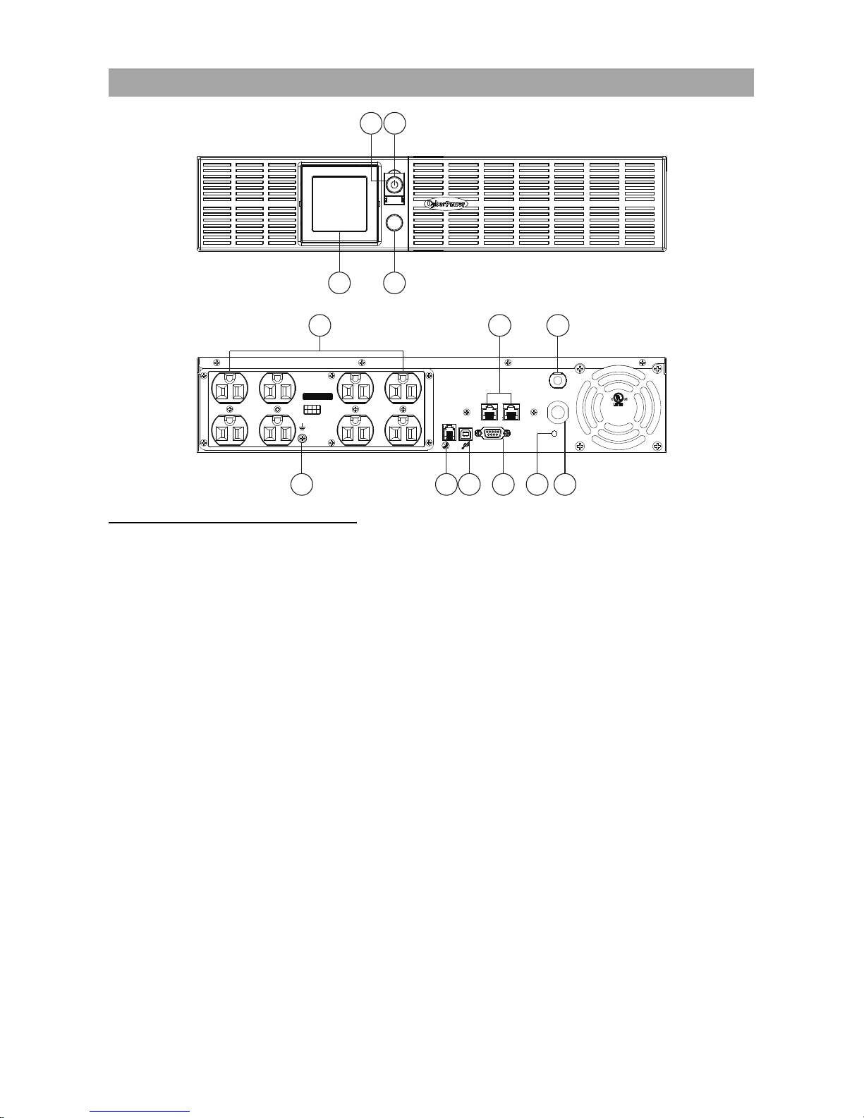
FRONT / REAR PANEL DESCRIPTION
1. Power Switch
Master on/off switch for equipment connected to the UPS.
2. Power On Indicator
An LED ring around the Power Switch indicates that the AC utility input power condition is normal and that
the UPS outlets are providing power, free of surges and spikes.
3. Multifunction LCD Readout
An LCD that shows various UPS information using icons and messages.
4. Display Toggle Button
Used to select among a variety of information the LCD can display.
5. Battery Backup, Surge Protected and AVR protected Outlets
This unit provides a total of 8 outlets with battery backup and surge protection. They ensure that
connected equipment will keep an uninterrupted operation over a period of time, during a power failure.
6. AC Input Power Cord
Connect the AC Power cord to a properly wired and grounded outlet.
7. Input Circuit Breaker
The circuit breaker serves to provide input overload and fault protection.
8. Serial Port
The serial port allows communication between the UPS and the computer. The UPS can control the
computer’s shutdown in case of an emergency, and the computer can monitor the UPS and alter its
various programmable parameters.
BASIC OPERATIO
N
Page 6

5 Copyright © 2016 CyberPower Systems, Inc.
9. USB port to PC
This is a connectivity port allowing communication and control between the UPS and the connected
computer. You should install on your computer the PowerPanel® Business Edition software appropriate to
the operating system you are using.
10. EPO (Emergency Power Off) Port
Allow for an emergency UPS Power-Off from a remote location.
11. Surge Protected Communication Ports - RJ11/RJ45
These ports are used to protect from various surge-conditions the standard RJ-45/RJ-11 based, (ADSL,
LAN, Phone/Modem-Lines), cabling systems.
12. Wiring Fault Indicator (Red)
This LED indicator will illuminate to warn the user that a wiring problem exists, such as bad ground,
missing ground or reversed wiring. If this is illuminated, disconnect all electrical equipments from the
outlet and have an electrician verify the outlet is properly wired. The unit will not provide surge protection
without being plugged into a grounded and properly wired wall outlet.
13. TVSS Screw
Use the Transient Voltage Surge Supression screw to ground the UPS.
Read and follow the IMPORTANT SAFETY INSTRUCTIONS before servicing the batteries:
Replacement of batteries located in an OPERATOR ACCESS AREA. Contact your dealer or call the
number on this manual for more information on battery replacement.
CAUTION! RISK OF EXPLOSION IF BATTERY IS REPLACED BY AN INCORRECT TYPE. DISPOSE
OF USED BATTERIES ACCORDING TO THE INSTRUCTIONS.
CAUTION! When replacing batteries, replace with the same number of the following battery: CyberPower
(RB1290X2C) for model OR1000PFCRT2U, CyberPower (RB1270X4G) for model OR1500PFCRT2U
and CyberPower (RB1290X4H) for model OR2200PFCRT2U.
CAUTION! Risk of Energy Hazard, 12 V, maximum 7Ah (for OR1500PFCRT2U) or 9Ah (for the
OR1000PFCRT2U and OR2200PFCRT2U) battery. Before replacing batteries, remove conductive
jewelry such as chains, wrist watches, and rings. High energy conducted through these materials could
cause severe burns.
CAUTION! Do not dispose of batteries in a fire. The batteries may explode. Follow all local ordinances
regarding the proper disposal of batteries.
CAUTION! Do not open or mutilate batteries. Released material is harmful to the skin and eyes. It may
be toxic.
Take the following precautions before replacing the battery:
1.
Remove all watches, rings or other metal objects from your hands.
2.
Only use tools with insulated handles.
3.
DO NOT lay tools or other metal parts on top of battery or any battery terminals.
4.
Wear rubber gloves and shoes.
5.
Determine if the battery is grounded. If so, remove source of ground. CAUTION: CONTACT WITH A
GROUNDED BATTERY CAN RESULT IN ELECTRICAL SHOCK! The likelihood of such a shock will
be greatly reduced if such grounding is removed during installation and maintenance.
BATTERY REPLACEMENT
BASIC OPERATIO
N (continued)
Page 7

Copyright © 2016 CyberPower Systems, Inc.
6
BATTERY REPLACMENT PROCEDURE
*BATTERY WIRING
Connect RED battery cable/connector to RED connector (positive to positive) on battery pack.
Connect BLACK battery cable/connector to BLACK connector (negative to negative) on battery pack.
REMINDER! The used batteries are considered hazardous waste and must be disposed through
recycling. Most retailers that sell lead-acid batteries collect used batteries for recycling, as required by the
local regulations.
BATTERY REPLA
CEMEN
T (continued)
1
2
4
3
Disconnect the black wire and red wire
from the battery.
Remove the front panel on the right
side.
Insert the new battery pack. Assemble
the screws, cable and front panel in
the reverse sequence of above steps.*
Recharge the unit for 18 hours to
ensure the UPS performs expected
runtime.
Remove the four retaining screws.
Page 8

7 Copyright © 2016 CyberPower Systems, Inc.
The LCD displays detailed information on the
UPS status and current power conditions to
alert you to potential power problems before
the affect your equipment. Note! All related
UPS information is based on that you should
turn on the UPS.
1
10
11
4 5 6 7 8 9
2 3
1.
Input Voltage Meter: This meter measures the AC voltage
from the wall outlet. The INPUT voltage readout is used to
identify the input voltage information. This can be used as a
diagnostic tool to identify poor-quality input power. Units are
listed in V (Volts).
2.
Output Voltage Meter: The Output Voltage screen
measures, in real time, the AC voltage that the UPS is
providing to your connected equipment via the UPS outlets.
Units are listed in V (Volts). In the event of a complete loss of
power, severe brownout, or over voltage, the UPS relies on
its internal battery to back up to supply a consistent
110/120V output.
3.
Estimated Runtime: The Estimated Runtime Screen
displays how many minutes of runtime can be expected of
the UPS if it were to experience a power outage. When
runtime becomes shorted, the battery capacity will decrease.
(The battery capacity bar indicator will be falling.) Note: The
number displayed may be less than actual runtimes for low
loads.
4.
Normal Icon: This icon illuminates when the UPS is working under normal conditions.
5.
Battery Icon: When there is a severe brownout or blackout, this icon will appear followed by an
alarm, (two short beeps), indicating that the UPS is now working using its internal batteries. Once
the batteries are running out of power, (over a period of time), the alarm will beep rapidly every 1/2
second. If this happens and main power has not been restored, it is recommended that you save
your files and turn off your equipment manually as soon as possible.
6.
Automatic Voltage Regulation (AVR) Icon: This icon will appear when the unit is automatically
regulating low or high AC input line voltage conditions, without resulting to the use of battery power.
This is a normal, automatic operation of your UPS, and no action is required on your part.
7.
Silent Mode Icon: This icon appearing indicates that the buzzer will not be beeping while in battery
operating mode. During Silent mode, the unit’s alarm does not sound until the battery reaches low
capacity threshold.
8.
Overload Icon: This icon will appear followed by an alarm, indicating that an overload condition has
been reached. To recover from the overload condition, start unplugging your equipment from the
UPS outlets until the icon disappears and the alarm stops.
9.
Fault Icon: When activated indicates there is a problem with the UPS. Please refer to FAULT
WARNING DISPLAY AND ALARM section.
10.
BATT. CAPACITY: BATT. CAPACITY is shown as a bar chart; each segment indicates
approximately a 20% of battery capacity.
11.
LOAD CAPACITY: Load CAPACITY is shown as a bar chart; each segment indicates approximately
a 20% of load capacity.
DEFINITION
FOR ILLUMINATED
LCD
INDICATORS
Page 9

Copyright © 2016 CyberPower Systems, Inc.
8
1. GENERAL MODE
a.
Press the Display toggle button to check the status of the UPS status:
# Items Unit
1 Input Voltage V
2 Output Voltage V
3 Output Frequency Hz
4 Load Kw
5 Load Capacity %
6 Battery Capacity %
7 Estimated Runtime Min
b.
If the LCD backlight turns off (enters sleeping mode), press the Display toggle button to wake it up.
2. SET-UP MODE
Step 1: Press and hold the Display toggle button for 3 seconds to enter the UPS Set-Up Mode.
Step 2: By pressing the Display toggle, users can switch between setup functions.
Step 3: Press and hold the Display toggle button for 3 seconds to choose the function you want to adjust.
When the icons blink, the value of each item is changed by slightly pressing the Display toggle button.
Note: If the function you select is ESC, the UPS will return to Function Menu (Step 2) without any change.
Step 4: To save the value and return to Function Menu, press and hold the toggle for 3 seconds.
Note: If the Display button is not touched for 30 seconds, the UPS will leave Set-up Mode and return to
General Mode without changing any settings.
Programmable functions are sorted as the following table:
Functions Options Description
Output Quality
Low
Low Output Quality means UPS will go to
battery mode less often and tolerate more
utility power fluctuations and vice versa.
Note: It is related to the settings of
High/Low Transfer Point. The LCD shows
“CUSt”, instead of “LInE”, with capacity bar
when High/Low Transfer Point is modified.
Medium
High
ESC
Customized
High Transfer Point
136V
It is the setting of maximum output
voltage. If the utility voltage is usually high
and the connected equipment can work
with this condition, you can set High
Transfer Point higher to avoid UPS going
to battery mode too often.
139V
142V
ESC
LCD SETUP FUCTIONS
Page 10

9 Copyright © 2016 CyberPower Systems, Inc.
Functions Options Description
Low Transfer Point
98V
It is the setting of minimum output voltage.
If the utility voltage is usually low and the
connected equipment can work with this
condition, you can set Low Transfer Point
lower to avoid UPS going to battery mode
too often.
100V
102V
ESC
Sensitivity
Low
If the connected equipment can tolerate
more power events, select Low Sensitivity.
The UPS will go to battery mode less
often. If the connected equipment cannot
tolerate power events, select High
Sensitivity. The UPS will go to battery
mode more often.
Meduim
High
ESC
Self Test
Yes
During a Self Test, UPS will switch from
line mode to battery mode to simulate the
power failure condictions.
ESC
Buzzer
On
If OFF is selected, the unit will mute all
alarms except for overload condition.
Off
ESC
LCD Sleeping Mode
On
Select ON, the LCD will enter sleeping
mode if the display toggle is not touched
for 1 minute. To illuminate the LCD, simply
press the display toggle once. When OFF
is chosen, the LCD will never enter
sleeping mode.
Note: In Battery Mode, the LCD is always
on.
Off
ESC
Back to Default
Yes
Restore the UPS factory default settings.
ESC
ESC
- Return to General Mode.
LCD SETUP FUCTIONS
(continued)
Page 11

Copyright © 2016 CyberPower Systems, Inc.
10
DURING SHUTDOWN
The following table shows each corresponding warning message on LCD display and the alarm reacts
during the machine shutdown (output-off):
LCD Warning
Display
Alarm Condition Solution
Constant
tone
Overload in line mode.
Turn the UPS off, unplug at least
one piece of equipment from battery
outlets, wait 10 seconds, reset the
circuit breaker and turn the unit on.
Constant
tone
Overload in battery mode.
Turn the UPS off, unplug at least
one piece of equipment from battery
outlets, wait 10 seconds, reset the
circuit breaker and turn the unit on.
(Flashing)
Rapid Beep
(30
seconds)
Battery missing in line
mode.
Turn the UPS off. Check battery
wiring and the presence of the
battery. Press the Display toggle
button to stop the alarm.
Beep twice
every 30
seconds
Utility Failure. The UPS is
in battery mode.
Wait for the recovery of utility or try
other AC power source. Pressing
the Display toggle button for 2
seconds can enter slient mode.
Rapid Beep
(every 1/2
second)
Utility Failure. The UPS is
in battery mode and will
run out of power shortly.
Recharge the battery.
AFTER SHUTDOWN
The following table shows the information about the error codes on LCD display after the machine
shutdown (output-off). The LCD will show the message till the UPS runs out of battery.
ERROR TYPE ERROR CODE POSSIBLE CAUSE
Line Mode Error E01 Battery Overcharge Charger broke down
System Error
E21 Output Short
UPS/connected devices short circuit
Output voltage detector broke down
Inverter fault
E22 Output Overload Too many connected devices
The Error code appears with Fault icon and a constant tone. Slightly press the Display toggle button once,
the constant beep will be cancelled.
To solve the problems, please refer to TROUBLESHOOTING section or contact CyberPower Systems at
tech@cpsww.com for further help and support.
FAULT
WARNING DISPLAY AND ALARM
Page 12

11 Copyright © 2016 CyberPower Systems, Inc.
Advanced Energy-Saving Patented Bypass Technology
CyberPower’s patented GreenPower UPS™ with Bypass Technology are ENERGY
STAR complainant ensuring lower power consumption and energy costs compared to
conventional UPS models. Even when utility power is normal, conventional UPS
models constantly pass power through a transformer. By contrast, under normal
conditions the advanced circuitry of a GreenPower UPS™ bypasses the transformer.
As a result, the power efficiency is significantly increased while decreasing waste heat,
using less energy, and reducing energy costs.
When an abnormal power condition occurs, the GreenPower UPS™ automatically
runs power through its transformer to regulate voltage and provide “safe” power. Since
utility power is normal over 88% of the time, the GreenPower UPS™ operates primarily in its efficient
bypass mode.
The GreenPower UPS™ is also manufactured in accordance with the Restriction on Hazardous
Substances (RoHS) directive making it one of the most environmentally-friendly on the market today.
CYBERPOWER GREENPOWER UPS™ TECHNOLOGY
Page 13

Copyright © 2016 CyberPower Systems, Inc.
12
MODEL OR1000PFCRT2U OR1500PFCRT2U OR2200PFCRT2U
INPUT
Nominal Input Voltage 120Vac
Input Voltage Range 88Vac – 139Vac
Input Adjustable Voltage Range 86Vac – 142Vac
Input Frequency Range 60Hz +/- 3Hz
Input Plug Type NEMA 5-15P NEMA 5-20P
OUTPUT
Output Capacity 1000VA / 700W 1500VA / 1050W 2000VA / 1540W
Output Receptacles (8) NEMA 5-15R
(2) NEMA 5-20R,
(6) NEMA 5-15R
On Battery Output Voltage Pure Sine Wave 120Vac +/- 5%*
On Battery Output Frequency 60Hz +/- 1%
Transfer Time (Typical) 4ms
Overload Protection Internal Current Limiting
SURGE PROTECTION AND FILTERING
Lightning / Surge Protection Yes
Internet Ready (DSL / Phone /
FAX / Modem Protection)
RJ11/RJ45 (One In/One Out)
BATTERY
Replacement Battery Pack RB1290X2C RB1270X4G RB1290X4H
Sealed Maintenance Free Yes
Recharge Time (Typical) 10 hours from total discharge
WARNING DIAGNOSTICS
Indicators Power On, LCD Display
Audible Alarms On Battery, Low Battery, Overload
ENVIRONMENTAL
Operating Temperature 32°F to 104°F ( 0°C to 40°C)
Operating Relative Humidity 0 to 95% Non-Condensing
Storage Temperature 5°F to 113°F ( -15°C to 45°C)
Storage Relative Humidity 0 to 95% Non-Condensing
MANAGEMENT
On-Device Features Manual Self-Test, Auto-Charge, Auto-Restart
Connectivity Ports (1) USB, (1) Serial port
SNMP/HTTP Networking Yes, with optional RMCARD205
Software PowerPanel® Business Edition
PHYSICAL
Dimensions (in) (mm) 2U Rack, 17” x 3.5” x 15.3” / 433 x 88 x 388 mm
Weight (lb) (kg) 37.5 lbs / 17kg 50.7 lbs / 23kg 57.3 lbs / 26kg
SAFETY
Conformance Approvals UL1778, cUL, FCC/Doc Class A
*For fully charged batteries.
TECHNICAL SPECIFICATIONS
Page 14

13 Copyright © 2016 CyberPower Systems, Inc.
Problem Possible Cause Solution
Outlet does not
provide power to
equipment.
Circuit breaker has tripped
due to an overload.
Turn the UPS off and unplug at least one
piece of equipment. Wait 10 seconds, reset
the circuit breaker and then turn the UPS on.
Batteries are discharged. Recharge the unit for at least 8 hours.
Unit has been damaged by a
surge or spike.
Contact CyberPower Systems for repair.
Uncritical outlets have turned
off automatically due to an
overload.
Push the toggle button to make the uncritical
outlets turn on.
The UPS does not
perform expected
runtime.
Batteries are not fully
charged.
Recharge the batteries by leaving the UPS
plugged in.
Batteries are degraded.
Contact CyberPower Systems about
replacement batteries at
www.cyberpowersystems.com.
The UPS will not turn
on.
The on/off switch is designed
to prevent damage by rapidly
turning it off and on.
Turn the UPS off. Wait 10 seconds and then
turn the UPS on.
The unit is not connected to
an AC outlet.
The unit must be connected to a 110/120V
60Hz outlet.
The batteries have degraded.
Contact CyberPower Systems about
replacement batteries at
www.cyberpowersystems.com.
Mechanical problem. Contact CyberPower Systems for repair.
PowerPanel®
Business Edition is
inactive.
The serial cable or USB cable
is not connected.
Connect the cable to the UPS unit. Use the
cable that came with the unit.
The cable is connected to the
wrong port.
Try another port of your computer.
The unit is not providing
power of batteries.
Shutdown your computer and turn the UPS
off. Wait 10 seconds and turn the UPS back
on. This should reset the unit.
Additonal troubleshooting information can be found at www.cyberpowersystems.com/support.
TROUBLE SHOOTING
Page 15

Copyright © 2016 CyberPower Systems, Inc.
14
Read the following terms and conditions carefully before using the CyberPower
OR1000PFCRT2U/OR1500PFCRT2U/OR2200PFCRT2U (the “Product”). By using the Product you
consent to be bound by and become a party to the terms and conditions of this Limited Warranty and
Connected Equipment Guarantee (together referred to as this “Warranty”). If you do not agree to the
terms and conditions of this Warranty, you should return the Product for a full refund prior to using it.
Who is Providing this Warranty?
CyberPower Systems (USA), Inc. (“CyberPower”) provides this Limited Warranty.
What Does This Warranty Cover?
This warranty covers defects in materials and workmanship in the Product under normal use and
conditions. It also covers equipment that was connected to the Product and damaged because of the
failure of the Product.
What is the Period of Coverage?
This warranty covers the Product for three years and connected equipment for as long as you own the
Product.
Who Is Covered?
This warranty only covers the original purchaser. Coverage ends if you sell or otherwise transfer the
Product.
How Do You Get Warranty Service?
1. Before contacting CyberPower, identify your Product model number, the Purchase Date, and each
item of Connected Equipment (E.G. Computer tower, Computer Monitor, Cable Modem, etc).
2. Visit our web site at https://www.cyberpowersystems.com/support or Call us at (877) 297-6937.
3. If your product requires warranty service you must provide a copy of your dated purchase receipt or
invoice.
How Do You Open A Connected Equipment Claim?
1. Call us at (877) 297-6937 or write to us at Cyber Power Systems (USA), Inc., 4241 12th Ave. E.,
STE 400, Shakopee, MN 55379, or send us an e-mail message at claims@cpsww.com for
instructions, within 10 days of the occurrence.
2. When you contact CyberPower, identify the Product, the Purchase Date, and the item(s) of
Connected Equipment. Have information on all applicable insurance or other resources of
recovery/payment that are available to the Initial Customer and Request a Claim Number.
3. You must provide a dated purchase receipt (or other proof of the original purchase) and provide a
description of the damage to your connected equipment.
4. Pack and ship the product to CyberPower and, if requested, the item(s) of Connected Equipment, a
repair cost estimate for the damage to the Connected Equipment, and all claim forms that
CyberPower provides to you. Show the Claim Number on the shipping label or include it with the
product. You must prepay all shipping costs, you are responsible for packaging and shipment, and
you must pay the cost of the repair estimate.
How Long Do I Have To Make A Claim?
All claims must be made within ten days of the occurrence.
LIMITED WARRANTY AND CONNECTED EQUIPMENT
GUARANTEE
Page 16

15 Copyright © 2016 CyberPower Systems, Inc.
What Will We Do To Correct Problems?
CyberPower will inspect and examine the Product.
If the Product is defective in material or workmanship, CyberPower will repair or replace it at
CyberPower's expense, or, if CyberPower is unable to or decides not to repair or replace the Product (if
defective) within a reasonable time, CyberPower will refund to you the full purchase price you paid for the
Product (purchase receipt showing price paid is required).
If it appears that our Product failed to protect any equipment plugged into it, we will also send you forms
for making your claim for the connected equipment. We will repair or replace the equipment that was
damaged because of the failure of our Product or pay you the fair market value (NOT REPLACEMENT
COST) of the equipment at of the time of the damage. We will use Orion Blue Book, or another a
third-party valuation guide, or eBay, craigslist, or other source to establish that amount. Our maximum
liability is limited to $300,000 for the OR1000PFCRT2U, OR1500PFCRT2U and OR2200PFCRT2U.
Who Pays For Shipping?
We pay when we send items to you; you pay when you send items to us.
What isn’t covered by the warranty?
1. This Warranty does not cover any software that was damaged or needs to be replaced due to the
failure of the Product or any data that is lost as a result of the failure or the restoration of data or
records, or the reinstallation of software.
2. This Warranty does not cover or apply to: misuse, modification, operation or storage outside
environmental limits of the Product or the equipment connected to it, nor for damage while in transit
or in storage, nor if there has been improper operation or maintenance, or use with items not
designed or intended for use with the Product, such as laser printers, appliances, aquariums,
medical or life support devices, etc.
What are the Limitations?
The sole and exclusive remedies of the Initial Customer are those provided by this Warranty.
1. This Warranty does not apply unless the Product and the equipment that was connected to it were
connected to properly wired and grounded outlets (including compliance with electrical and safety
codes of the most current electrical code), without the use of any adapters or other connectors.
2. The Product must have been plugged directly into the power source and the equipment connected to
the Product must be directly connected to the Product and not “daisy-chained” together in serial
fashion with any extension cords, another Product or device similar to the Product, surge suppressor,
or power tap. Any such installation voids the Limited Warranty.
3. The Product and equipment connected to it must have been used properly in a suitable and proper
environment and in conformance with any license, instruction manual, or warnings provided with the
Product and the equipment connected to it.
4. The Product must have been used at all times within the limitations on the Product’s VA capacity.
The Product was designed to eliminate disrupting and damaging effects of momentary (less than 1ms)
voltage spikes or impulses from lightning or other power transients. If it can be shown that a voltage
spike lasting longer than 1ms has occurred, the occurrence will be deemed outside the rated capabilities
of the Product and the Limited Warranty is void. CyberPower Does Not Cover or Undertake Any Liability in
Any Event for Any of the Following:
1. Loss of or damage to data, records, or software or the restoration of data or records, or the
reinstallation of software.
LIMITED WARRANTY AND CONNECTED EQUIPMENT GUARANTEE
Page 17

Copyright © 2016 CyberPower Systems, Inc.
16
2. Damage from causes other than AC Power Line Transients, spikes, or surges on properly installed,
grounded and code-compliant 120 volt power lines in the United States and Canada; transients,
surges or spikes on standard telephone land lines, PBX telephone equipment lines or Base 10T
Ethernet lines, when properly installed and connected. (This exclusion applies, for example, to
fluctuations in data transmission or reception, by CATV or RF transmission or fluctuations, or by
transients in such transmission.)
3. Damage from any circumstance described as excluded above with respect to the Product.
4. Damages from fire, flood, wind, rain, rising water, leakage or breakage of plumbing, abuse, misuse
or alteration of either the product or the Connected Equipment.
5. CyberPower excludes any liability for personal injury under the Limited Warranty and Connected
Equipment Guarantee. CyberPower excludes any liability for direct, indirect, special, incidental or
consequential damages, whether for damage to or loss of property [EXCEPT FOR (AND ONLY FOR)
the specific limited agreement of CyberPower to provide certain warranty benefits regarding
"Connected Equipment" under this Warranty], loss of profits, business interruption, or loss of
information or data. NOTE: Some States or Provinces do not allow the exclusion or limitation of
incidental or consequential damages, so the above limitation may not apply to you.
6. The Product is not for use in high-risk activities or with aquariums. The Product is not designed or
intended for use in hazardous environments requiring fail-safe performance, or for use in any
circumstance in which the failure of the Product could lead directly to death, personal injury, or
severe physical or property damage, or that would affect operation or safety of any medical or life
support device (collectively, "High Risk Activities"). CyberPower expressly disclaims any express or
implied warranty of fitness for High Risk Activities or with aquariums. CyberPower does not authorize
use of any Product in any High Risk Activities or with Aquariums. ANY SUCH USE IS IMPROPER
AND IS A MISUSE OF THE PRODUCT.
Where Can I Get More Information?
The application of the United Nations Convention of Contracts for the International Sale of Goods is
expressly excluded. CyberPower is the warrantor under this Limited Warranty.
For further information please feel free to contact CyberPower at CyberPower Systems (USA), Inc. 4241
12th Ave E., STE 400, Shakopee, MN 55379; call us at (877) 297-6937; or send us an e-mail message at
claims@cpsww.com.
All rights reserved. Reproduction without permission is prohibited.
LIMITED WARRANTY AND CONNECTED EQUIPMENT GUARANTEE
Page 18

17 Copyright © 2016 CyberPower Systems, Inc.
FCC COMPLIANCE STATEMENT
This device complies with part 15 of the FCC rules. Operation is subject to the following two conditions: (1)
this device may not cause harmful interference, and (2) this device must accept any interference received,
including interference that may cause undesired operation.
Note: This equipment has been tested and found to comply with the limits for a Class A digital device,
pursuant to part 15 of the FCC Rules. These limits are designed to provide reasonable protection against
harmful interference when the equipment is operated in a commercial environment. This equipment
generates, uses, and can radiate radio frequency energy and, if not installed and used in accordance with
the instruction manual, may cause harmful interference to radio communications. Operation of this
equipment in a residential area is likely to cause harmful interference in which case the user will be
required to correct the interference at his own expense.
Important: Changes or modifications not expressly approved by the party responsible for compliance
could void the user's authority to operate the equipment.
CAN ICES-3 (A)/NMB-3(A)
SAFETY COMPLIANCE STATEMENT
Page 19

Page 20

For more information, contact us at
CyberPower Systems, Inc.
Website: www.cyberpower.com
ENTIRE CONTENTS COPYRIGHT © 2016 CYBERPOWER SYSTEMS, INC.
ALL RIGHTS RESERVED. REPRODUCTION IN WHOLE OR IN PART WITHOUT
PERMISSION IS PROHIBITED.
 Loading...