

CyberPower OR1000PFCRT2U, OR1500PFCRT2U, OR2200PFCRT2U User Manual

USER’S MANUAL
PFC SINEWAVE SERIES
OR1000PFCRT2U/OR1500PFCRT2U/
OR2200PFCRT2U
K01-0000488-01
EN

1 Copyright © 2016 CyberPower Systems, Inc.
This manual contains important instructions. Please read and follow all instructions carefully during
installation and operation of the unit. Read this manual thoroughly before attempting to unpack, install, or
operate the UPS.
CAUTION! To prevent the risk of fire or electric shock, install in a temperature and humidity controlled
indoor area free of conductive contaminants. (Please see specifications for acceptable temperature and
humidity range).
CAUTION! For pluggable equipment, the socket-outlet shall be installed near the equipment and shall
be easily accessible.
CAUTION! To reduce the risk of electric shock, do not remove the cover except to service the battery.
Ensure the input power is removed before servicing the batteries. There are no user serviceable parts
inside except for the battery.
CAUTION! Hazardous live parts inside can be energized by the battery even when the AC input power
is disconnected.
CAUTION! The UPS must be connected to an AC power outlet with fuse or circuit breaker protection.
Do not plug into an outlet that is not grounded. If you need to de-energize this equipment, turn off and
unplug the unit.
CAUTION! To avoid electric shock, turn off the unit and unplug it from the AC power source before
servicing the battery or installing a computer component.
CAUTION! To reduce the risk of fire, connect only to a circuit provided with 20 amperes maximum
branch circuit over current protection in accordance with the National Electric Code, ANSI/NFPA 70.
CAUTION! The UPS is suitable for use in a computer room as defined in the Standard for the Protection
of Electronic Computer/Data Processing Equipment, ANSI/NFPA 75.
CAUTION! The EPO function is provided in UPS. EPO remote switch which is Push-Back button is
installed computer room outside by a phone line and not connected any other equipment.
CAUTION! DO NOT USE FOR MEDICAL OR LIFE SUPPORT EQUIPMENT! Under no circumstances
this unit should be used for medical applications involving life support equipment and/or patient care.
CAUTION! DO NOT USE WITH OR NEAR AQUARIUMS! To reduce the risk of fire, do not use with or
near aquariums. Condensation from the aquarium can come in contact with metal electrical contacts and
cause the machine to short out.
CAUTION! DO NOT USE WITH LASER PRINTERS! The power demands of laser printers are too large
for a UPS.
CAUTION! DO NOT INSTALL THE UPS WHERE IT WOULD BE EXPOSED TO DIRECT SUNLIGHT
OR NEAR A STRONG HEAT SOURCE!
CAUTION! DO NOT BLOCK OFF VENTILATION OPENINGS AROUND THE HOUSING!
CAUTION! DO NOT CONNECT DOMESTIC APPLIANCES SUCH AS HAIR DRYERS TO UPS
OUTPUT SOCKETS.
IMPORTANT SAFETY INSTRUCTIONS
Copyright © 2016 CyberPower Systems, Inc.
2
UNPACKING
The box should contain the following:
(a) UPS unit x1; (b) User manual x1; (c) USB A+B type cable x1; (d) Rackmount bracket x2; (e) Vertical
stand x2; (f) Warranty registration card x1
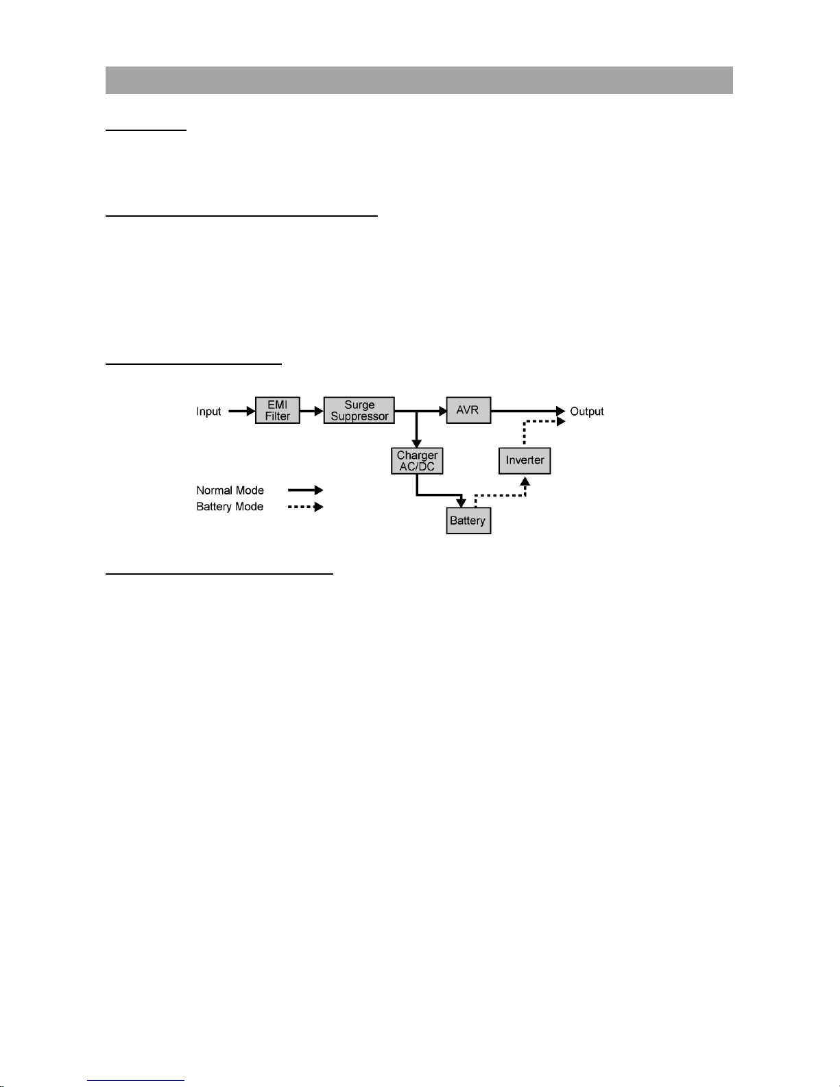
AUTOMATIC VOLTAGE REGULATOR(AVR)
The OR1000PFCRT2U/OR1500PFCRT2U/OR2200PFCRT2U can stabilize inconsistent utility power.
Incoming utility power fluctuations may be damaging to important data and hardware but Automatic
Voltage Regulation (AVR) helps protect the computer against experiencing dangerous voltage levels. AVR
automatically adjusts low or high voltages to keep equipment working at safe AC power levels (110/120V)
without switching to battery. Your equipment can operate normally even during the power problems such
as brownouts and blackouts. The unit’s powerful sealed lead-acid batteries will provide power only if the
incoming voltage drops below 90V or increases above 140V.
SYSTEM BLOCK DIAGRAM
HARDWARE INSTALLATION GUIDE
1. Battery charge loss may occur during shipping and storage. The first time the UPS is used, it is
strongly recommended to charge the batteries for at least 18 hours to ensure that the batteries are at
their maximum charge capacity. To recharge the batteries, simply plug the UPS into an AC outlet, the
batteries will charge whether the UPS is powered on or not.
2. With the UPS off and unplugged, connect your computer, monitor, and any externally powered data
storage device (Hard drive, Tape drive, etc.) into the outlets. DO NOT plug a laser printer, copier,
space heater, vacuum, paper shredder or other large electrical device into the UPS. The power
demands of these devices will overload and possibly damage the unit.
3. To protect a fax, telephone, modem line or network cable, connect the telephone or network cable
from the wall jack outlet to the jack marked “IN” on the UPS. Then, connect a telephone cable or
network cable from the jack marked “OUT” on the UPS to the modem, computer, telephone, fax
machine, or network device.
4. Plug the UPS into a 2 pole, 3 wire grounded receptacle (wall outlet). Make sure the wall branch outlet
is protected by a fuse or circuit breaker and does not service equipment with large electrical demands
(e.g. air conditioner, copier, etc). The warranty prohibits the use of extension cords, outlet strips, and
surge strips.
INSTALLING YOUR UPS SYSTEM
(continued)
INSTALLING YOUR UPS SYSTEM

3 Copyright © 2016 CyberPower Systems, Inc.
5. Press the power switch to turn the UPS on. The Power-On indicator light will illuminate. If an overload
is detected, an audible alarm will sound and the UPS will emit one long beep. In order to reset it, turn
the unit off and unplug some equipment from outlets. Make sure the total load of the equipment
connected to the UPS is within the unit’s safe range, (refer to the technical specifications), and then
turn the unit on.
6. To maintain an optimal battery charge, leave the UPS plugged into an AC outlet at all times.
7. Before storing the UPS for an extended period of time, turn the unit OFF. Then cover it and store it
with the batteries fully charged. Recharge the batteries every three months or so, to ensure good
battery capacity and long battery life; further, this might also prevent damage to the unit from an
unlikely battery leakage.
8. The unit provides one Serial port and one USB port to allow connection and communication between
the unit and any attached computers. The Serial Port as well as its paired USB port allow for
bi-directional communication among the UPS and the primary connected computer running the
PowerPanel® Business Edition Software. The computer can monitor the UPS and alter its various
programmable parameters. When there is a power failure, the computer connected to the port will
start to shut down after a user controlled delay based on the settings given to the PowerPanel®
Business Edition Software.
Note: If the USB port is used, the serial port will be disabled. They cannot be used simultaneously.
Note: PowerPanel® Business Edition Software is available on our website. Please visit
www.cyberpowersystems.com and go to Products/Software page for free download.
9. EPO (Emergency Power Off) Port:
Follow the appropriate circuit diagram below to wire the cable to your EPO configuration. The EPO
remote switch is a switch installed in an outside area, connected to the unit via an ordinary RJ-11
phone line. In case of an emergency, it can be used to immediately cut-off power from the UPS unit.
RJ11
PLUG
1
2
3
4
3-4 JUMPER
N.C.EPO SWITCH
OPTION 2: USER SUPPLIED NORMALLY CLOSED SWITCH
RJ11
PLUG
1
2
3
4
NO CONNECTION
N.O.EPO SWITCH
OPTION 1: USER SUPPLIED NORMALLY OPEN SWITCH
(RECOMMENDED)
NO CONNECTION
INSTALLING YOUR UPS SYSTEM
(continued)
Copyright © 2016 CyberPower Systems, Inc.
4
SELECT
ON/OFF
AC INPUT
IN OUT
Push To
RESET
EPO
Serial Port
FAULT
WIRING
6G48
E187679
POWER SUPPLY
UNINTERRUPTIBLE
21
4
3
6587
Max / Outlets
15 Amps
1
711
5
6
2
3
12891013
4
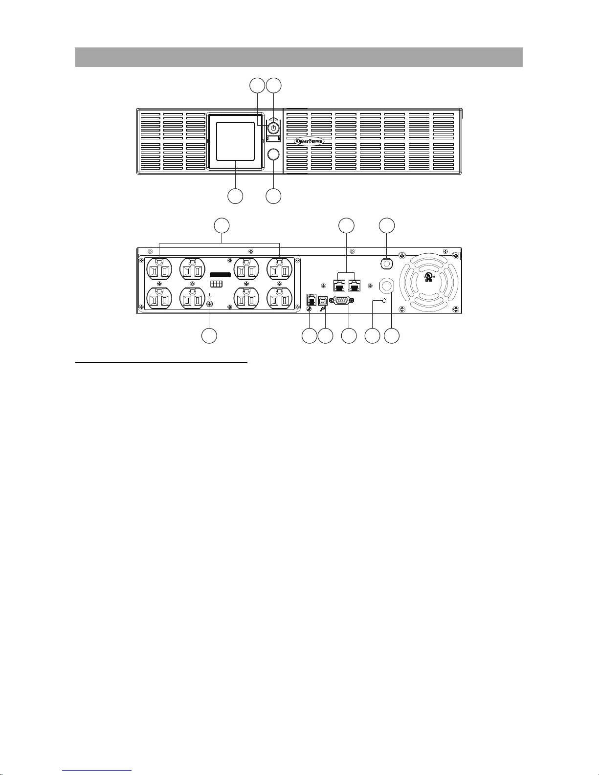
FRONT / REAR PANEL DESCRIPTION
1. Power Switch
Master on/off switch for equipment connected to the UPS.
2. Power On Indicator
An LED ring around the Power Switch indicates that the AC utility input power condition is normal and that
the UPS outlets are providing power, free of surges and spikes.
3. Multifunction LCD Readout
An LCD that shows various UPS information using icons and messages.
4. Display Toggle Button
Used to select among a variety of information the LCD can display.
5. Battery Backup, Surge Protected and AVR protected Outlets
This unit provides a total of 8 outlets with battery backup and surge protection. They ensure that
connected equipment will keep an uninterrupted operation over a period of time, during a power failure.
6. AC Input Power Cord
Connect the AC Power cord to a properly wired and grounded outlet.
7. Input Circuit Breaker
The circuit breaker serves to provide input overload and fault protection.
8. Serial Port
The serial port allows communication between the UPS and the computer. The UPS can control the
computer’s shutdown in case of an emergency, and the computer can monitor the UPS and alter its
various programmable parameters.
BASIC OPERATIO
N

5 Copyright © 2016 CyberPower Systems, Inc.
9. USB port to PC
This is a connectivity port allowing communication and control between the UPS and the connected
computer. You should install on your computer the PowerPanel® Business Edition software appropriate to
the operating system you are using.
10. EPO (Emergency Power Off) Port
Allow for an emergency UPS Power-Off from a remote location.
11. Surge Protected Communication Ports - RJ11/RJ45
These ports are used to protect from various surge-conditions the standard RJ-45/RJ-11 based, (ADSL,
LAN, Phone/Modem-Lines), cabling systems.
12. Wiring Fault Indicator (Red)
This LED indicator will illuminate to warn the user that a wiring problem exists, such as bad ground,
missing ground or reversed wiring. If this is illuminated, disconnect all electrical equipments from the
outlet and have an electrician verify the outlet is properly wired. The unit will not provide surge protection
without being plugged into a grounded and properly wired wall outlet.
13. TVSS Screw
Use the Transient Voltage Surge Supression screw to ground the UPS.
Read and follow the IMPORTANT SAFETY INSTRUCTIONS before servicing the batteries:
Replacement of batteries located in an OPERATOR ACCESS AREA. Contact your dealer or call the
number on this manual for more information on battery replacement.
CAUTION! RISK OF EXPLOSION IF BATTERY IS REPLACED BY AN INCORRECT TYPE. DISPOSE
OF USED BATTERIES ACCORDING TO THE INSTRUCTIONS.
CAUTION! When replacing batteries, replace with the same number of the following battery: CyberPower
(RB1290X2C) for model OR1000PFCRT2U, CyberPower (RB1270X4G) for model OR1500PFCRT2U
and CyberPower (RB1290X4H) for model OR2200PFCRT2U.
CAUTION! Risk of Energy Hazard, 12 V, maximum 7Ah (for OR1500PFCRT2U) or 9Ah (for the
OR1000PFCRT2U and OR2200PFCRT2U) battery. Before replacing batteries, remove conductive
jewelry such as chains, wrist watches, and rings. High energy conducted through these materials could
cause severe burns.
CAUTION! Do not dispose of batteries in a fire. The batteries may explode. Follow all local ordinances
regarding the proper disposal of batteries.
CAUTION! Do not open or mutilate batteries. Released material is harmful to the skin and eyes. It may
be toxic.
Take the following precautions before replacing the battery:
1.
Remove all watches, rings or other metal objects from your hands.
2.
Only use tools with insulated handles.
3.
DO NOT lay tools or other metal parts on top of battery or any battery terminals.
4.
Wear rubber gloves and shoes.
5.
Determine if the battery is grounded. If so, remove source of ground. CAUTION: CONTACT WITH A
GROUNDED BATTERY CAN RESULT IN ELECTRICAL SHOCK! The likelihood of such a shock will
be greatly reduced if such grounding is removed during installation and maintenance.
BATTERY REPLACEMENT
BASIC OPERATIO
N (continued)
 Loading...