

Cyber Power OLS6000ERT6U, OLS6000ERT6UM, OLS10000ERT6U, OLS10000ERT6UM User Manual

Userˊs Manual
OLS6000ERT6U
OLS10000ERT6U
OLS6000ERT6UM
OLS10000ERT6UM
CyberPower Systems Inc.
www.cyberpower.com
K01-C000250-02

CONTENT:
1. Safety ..............................................................................................................1
1.1. Installation ..................................................................................................1
1.2. Operation ....................................................................................................1
1.3. Maintenance, Servicing and Faults .............................................................2
1.4. Transport ....................................................................................................3
1.5. Storage ....................................................................................................... 3
1.6. Standards ...................................................................................................3
2. Description of Commonly Used Symbols ....................................................4
3. Introduction ....................................................................................................4
3.1. Feature .......................................................................................................5
3.2. Electrical Specifications .............................................................................. 6
3.3. Operating Environment ...............................................................................7
3.4. Dimensions and Weights ................................................................ ............7
4. Unpacking .......................................................................................................8
5. Hardware Installation ................................................................................... 11
5.1. Rackmount Installation ............................................................................. 11
5.2. Vertical/Tower Installation ......................................................................... 13
6. Electrical Installation ................................................................................... 16
6.1. Power Wires Installation ........................................................................... 16
6.2. Operating Procedure for Connecting with the Battery module .................. 19
6.3. EPO Connection ....................................................................................... 20
7. Operation ................................................................ ...................................... 21
7.1. Display Panel ............................................................................................ 21
7.2. Turning On and Turning Off UPS .............................................................. 23
7.3. LCD Operation .......................................................................................... 24
8. Special Function .......................................................................................... 29
8.1. ECO Function ........................................................................................... 29
8.2. Converter Function ................................................................................... 29
8.3. Parallel Function ....................................................................................... 30
9. Trouble Shooting ......................................................................................... 34
9.1. Trouble Shooting According To Warning Indication .................................. 34
9.2. Trouble Shooting According To Fault Indication ....................................... 36
9.3. Trouble Shooting In Else Cases ............................................................... 37

10. Battery Maintenance .................................................................................. 38
11. Communication Port .................................................................................... 39
11.1. USB Interface ......................................................................................... 39
11.2. RS232 Interface ..................................................................................... 39
11.3. Intelligent slot ......................................................................................... 39

1
1. Safety
Please read carefully the following user manual and the safety instructions
before installing the unit or using the unit!
1.1. Installation
This is permanently connected equipment, and it must be installed by qualified
maintenance personnel.
Condensation may occur if the UPS is moved directly from a cold to a warm
environment. The UPS must be absolutely dry before being installed. Please
allow an acclimatization time of at least two hours.
Do not install the UPS near water or in damp environment.
Do not install the UPS where it would be exposed to direct sunlight or near heat.
Do not connect appliances or items of equipment which would overload the UPS
(e.g. laser printers, etc.) to the UPS output.
Do not block ventilation openings in the UPS’s housing. Ensure allow at least
0.5m of space on front and rear of the UPS.
Place cables in such a way that no one can step on or trip over them.
Connect UPS with the earth reliably before connecting to the building wiring
terminal, and external battery source must also be earthed.
An integral single emergency switching device which prevents further supply to
the load by the UPS in any mode of operation should be provided in the building
wiring installation.
An appropriate disconnect device as short-circuit backup protection should be
provided in the building wiring installation.
The equipment is powered by two sources: the mains source, the internal
battery or the external battery source.
With the installation of the equipment, the sum of the leakage current of the UPS
and the connected load does not exceed 5% of rated value of input current.
1.2. Operation
Do not disconnect the main cable on the UPS or the building wiring terminals
during operation since this would remove the protective earth from the UPS and
all connected loads.
The UPS output terminal block may still be electrically lived even if the UPS is

2
not connected to the building wiring terminal, for there is internal current source
(batteries).
In order to fully disconnect the UPS, first turn the input breaker in the "OFF"
position, then disconnect the mains lead.
Indiscriminate operation of switches may cause output loss or damage to
equipment. Refer to instruction before conducting any control.
While the UPS work as a parallel system, the external parallel cable should be
reinforced insulation.
Ensure that no liquid or other foreign objects can enter the UPS.
1.3. Maintenance, Servicing and Faults
Do not remove the enclosure since the UPS operates with hazardous voltages.
It is to be serviced only by qualified maintenance personnel.
Caution! Risk of electric shock. Even after the unit is disconnected from the
mains power supply (building wiring terminal) components inside the UPS are
still connected to the battery which are potentially dangerous.
Before carrying out any kind of service or maintenance, isolate UPS and
disconnect the batteries. Verify that no current is present and no hazardous
voltage exists in the capacitor or BUS capacitor.
Batteries must be replaced only by qualified personnel.
Batteries have a high short-circuit current and pose a risk of shock. Take all
precautionary measures specified below and any other necessary measures
when working with batteries:
─ remove all jewellery, wristwatches, rings and other metal objects
─ use only tools with insulated grips and handles.
When changing batteries, replace with the same quantity and the same type of
batteries.
Do not attempt to dispose of batteries by burning them. It could cause explosion.
The UPS may be connected to Battery pack. Proper disposal of batteries is
required. Refer to your local codes for disposal requirements.
Do not open or destroy batteries. Effluent electrolyte can cause injury to the skin
and eyes. It may be toxic.
Replace the fuse only by a fuse of the same type and of the same spec in order
to avoid fire hazards.

3
1.4. Transport
Please transport the UPS only in the original packaging to protect against shock
and impact.
1.5. Storage
The UPS must be stockpiled in the room where is ventilated and dry.
1.6. Standards
* Safety
IEC/EN 62040-1
* EMI
Conducted Emission................................:IEC/EN 62040-2
Category C3
Radiated Emission...................................:IEC/EN 62040-2
Category C3
*EMS
ESD....................................................... ..:IEC/EN 61000-4-2
Level 3
RS............................................................:IEC/EN 61000-4-3
Level 3
EFT..........................................................:IEC/EN 61000-4-4
Level 4
SURGE....................................................:IEC/EN 61000-4-5
Level 4
Low Frequency Signals............................:IEC/EN 61000-2-2
Warning: This is a product for commercial and industrial application in the
second environment-installation restrictions or additional measures may be
needed to prevent disturbances.
4
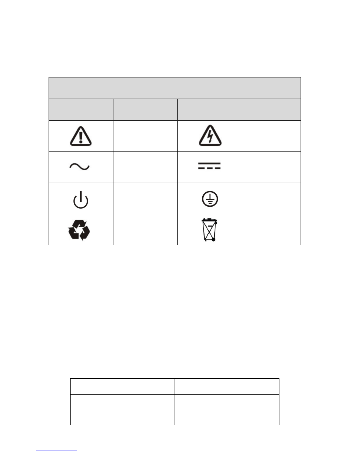
2. Description of Commonly Used Symbols
Some or all of the following symbols may be used in this manual. It is advisable to
familiarize yourself with them and understand their meaning:
3. Introduction
This On-Line series is an uninterruptible power supply incorporating
double-converter technology. It provides perfect protection specifically for computer
equipments, communication servers, and data centers.
The double-converter principle eliminates all mains power disturbances. A rectifier
converts the alternating current from the mains power to direct current. On the
basis of this DC voltage, the inverter generates an AC sinusoidal voltage, which
constantly supplies the loads. In the event of power failure, the maintenance-free
batteries power the inverter.
This manual covers the UPS listed as follows.
Mode NO.
Type
OLS6000ERT6U(M)
Standard
OLS6000ERT6U(M)
Symbol and Explanation
Symbol
Explanation
Symbol
Explanation
Alert you to pay
special attention
Caution of high
voltage
Alternating current
source(AC)
Direct current
source(DC)
Turn on or turn off
the UPS
Protective
ground
Recycle
Do not dispose
with ordinary
trash
5
3.1. Feature
This series UPS is a new generation of UPS, which provides the outstanding
reliability, and most cost-performance ratio in the industrial. Following benefit the
product has:
True online double-conversion technology with high power density, frequency
independence and generator compatibility.
High input power factor ≥0.99,overall high efficiency ≥ 92%, save power
and wiring expense. Low input current distortion, avoid power pollution.
Output power factor is 0.9, perfect output sine waveform, suitable almost all
critical equipment.
Outstanding adaptability to the worst mains input condition. Extra wide input
voltage, frequency range and waveform, avoid excessive dissipating limited
battery energy.
N+X parallel redundancy to increase the reliability and flexibility. Number of
parallel operating UPS is up to 4.
ECO mode with high efficiency ≥96%, save power expense for user.
Start-able without battery.
Automatically select charging current through the external Battery Type and
external battery pack setting.
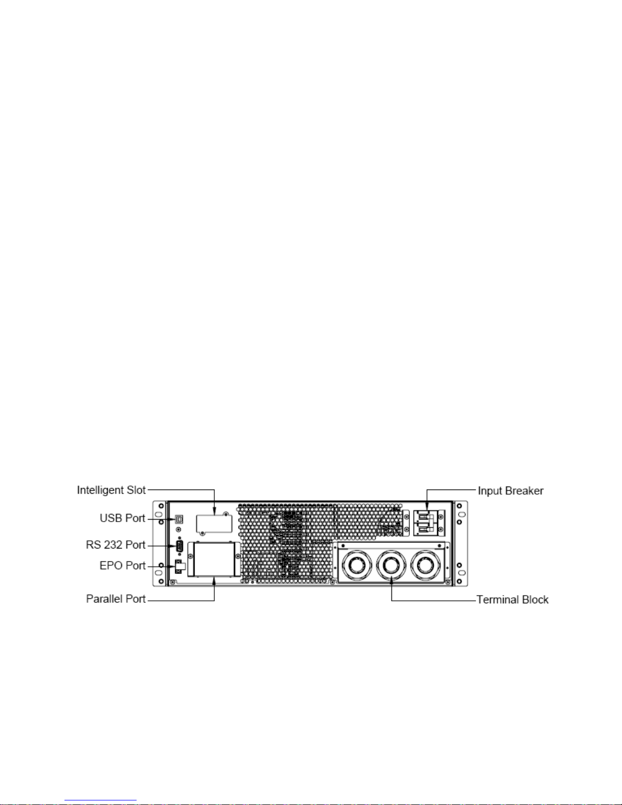
Fig.3-1 The rear view of OLS6000/10000ERT6U(M) Power module
6
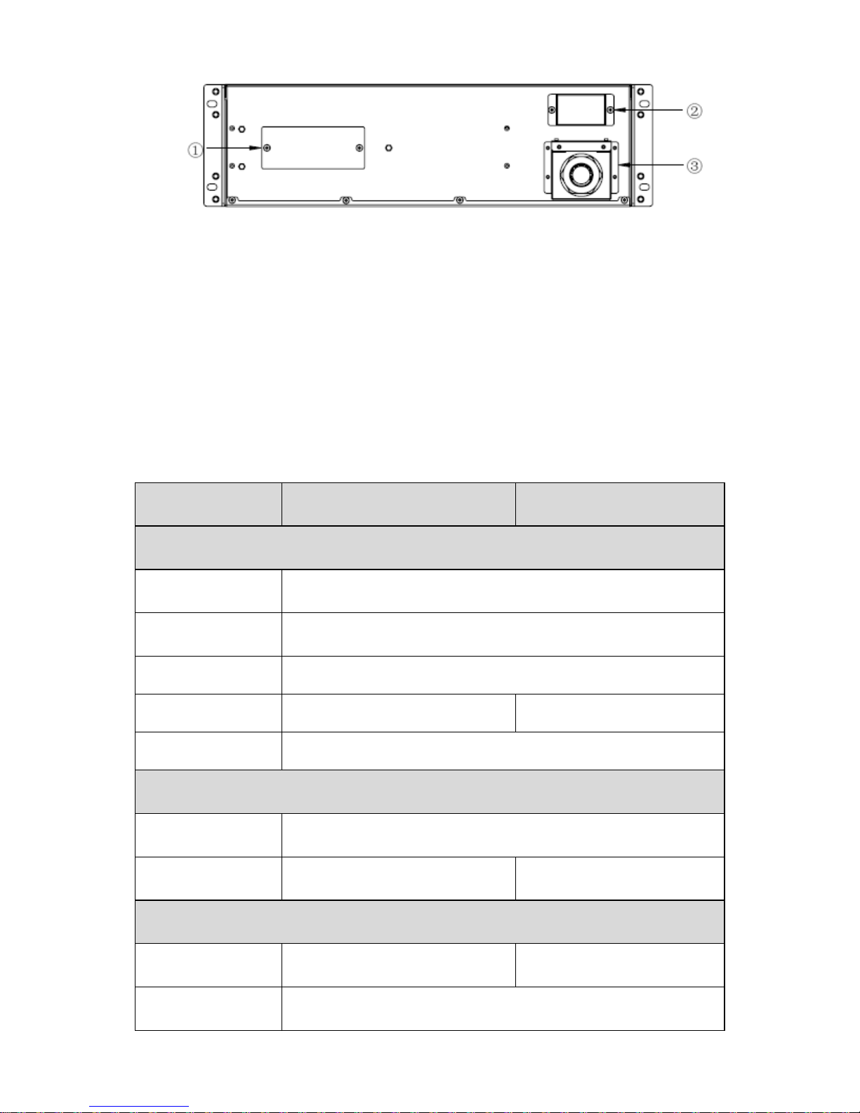
Fig.3-2 The rear view of OLS6000/10000ERT6U(M) Battery module
① Fuse: Replaceable fuse is accessible from the rear panel. It must be done by
qualified personnel.
② Output Connector: Use this output connector to connect the Battery module
and the Power module.
③ Battery Input Terminal Block: Use this input Terminal Block to daisy chain the
next Battery module.
3.2. Electrical Specifications
Model
OLS6000ERT6U(M)
OLS10000ERT6U(M)
Input
Phase
Single
Voltage Rage
110~276Vac (Depends on load level)
Frequency Rage
50/60±10%Hz
Rated Current
36A
55A
Power Factor
≥0.99 @ full load
Battery
Rated Voltage
240Vdc
Rated Current
28A
47A
Output
Power Rating
6kVA/5.4kW
10kVA/9kW
Voltage*
208/220/230/240Vac

7
Frequency
Synchronized 50/60×(1±10%)Hz @Line mode
50/60×(1±0.1%)Hz @Battery mode
Wave Form
sine
Load Type
PF 0.5~1, lagging
THDV
≤ 2% @ full linear load;≤5% @ full nonlinear load
Over Load**
Line mode:
10 min 105%~125%
1 min 125%~150%
10 s 150%~170%
100ms >170%
Battery mode:
2 min 105%~125%
30 s 125%~150%
100ms >150%
*The load capacity would be derated to 90% automatically when the output voltage
is adjusted to 208Vac.
**The overload capacity would be derated automatically in Line mode while the
circumstance temperature is larger than 35 degree.
3.3. Operating Environment
Temperature
Humidity
Altitude
Storage
0℃~40℃
<95%
<1000m
-15℃~50℃
Note: The load capacity should be derated 1% every 100m heightened on the basis
of 1000m.
3.4. Dimensions and Weights
Model
Dimensions
W×H×D(mm)
Net Weight(kg)
OLS6000ERT6U
438*261*680
72.5
OLS10000ERT6U
438*261*680
86
OLS6000ERT6UM
438*261*821
75.1
OLS10000ERT6UM
438*261*821
88.6
8
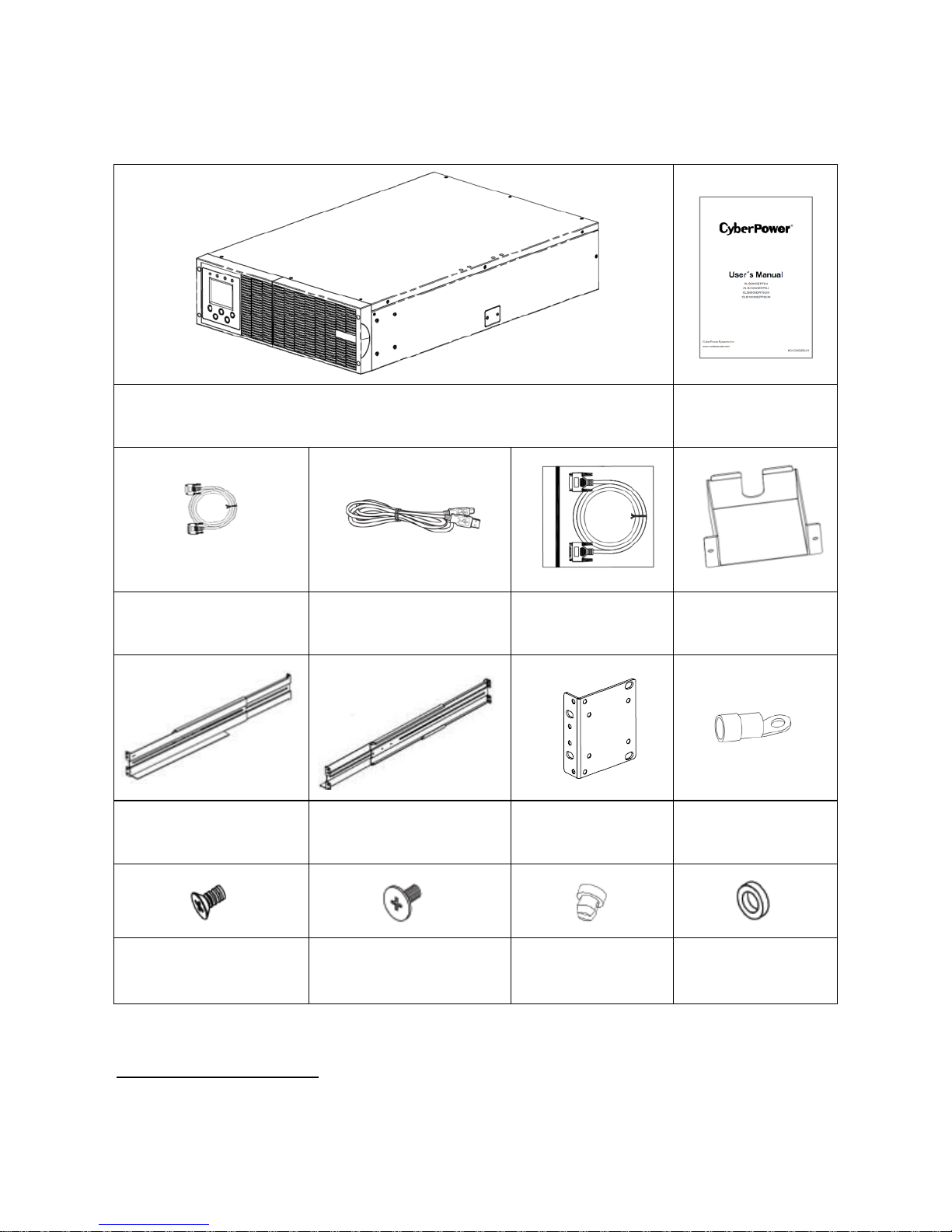
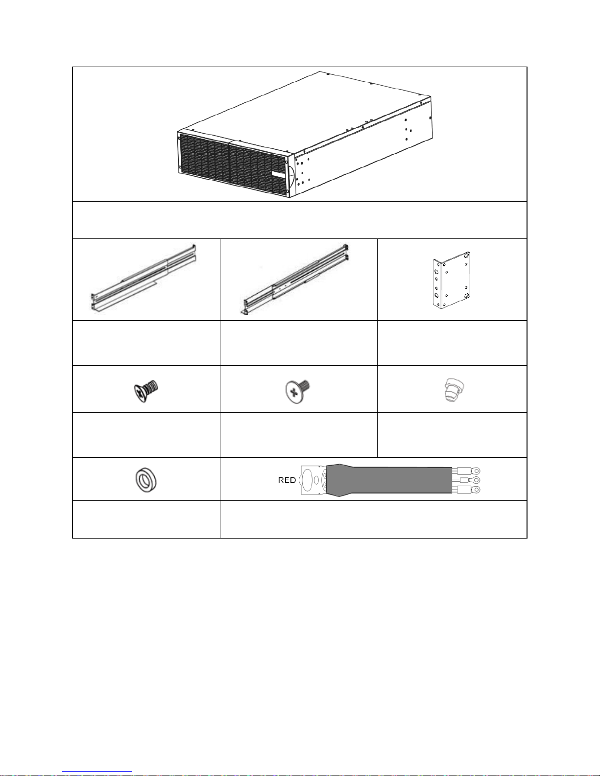
4. Unpacking
Power Module Contains:
Power Module
Power Module
User’s Manual
RS232 Cable
(optional)
USB Communication
Cable
Parallel Cable
Parallel Port
Cover Plate
Rackmount Left Rail
Rackmount Right Rail
Rackmount Ears
(Stands)*2PCS
Terminal*11PCS
Flat Head Screws:
M4X8L*8PCS
Pan Head Screws:
M5X12L*13PCS
Screw Hole Dust
Covers*8PCS
Plastic Washers
*8PCS
*PowerPanel® Personal Edition software is available on our website. Please visit
www.cyberpower.com and go to the Software Section for free download.
9
Battery Module Contains:
Battery Module
Rackmount Left Rail
Rackmount Right Rail
Rackmount Ears
(Stands)*2PCS
Flat Head Screws:
M4X8L*8PCS
Pan Head Screws:
M5X12L*13PCS
Screw Hole Dust
covers*8PCS
Plastic Washers*8PCS
Battery Cable(RED)
10
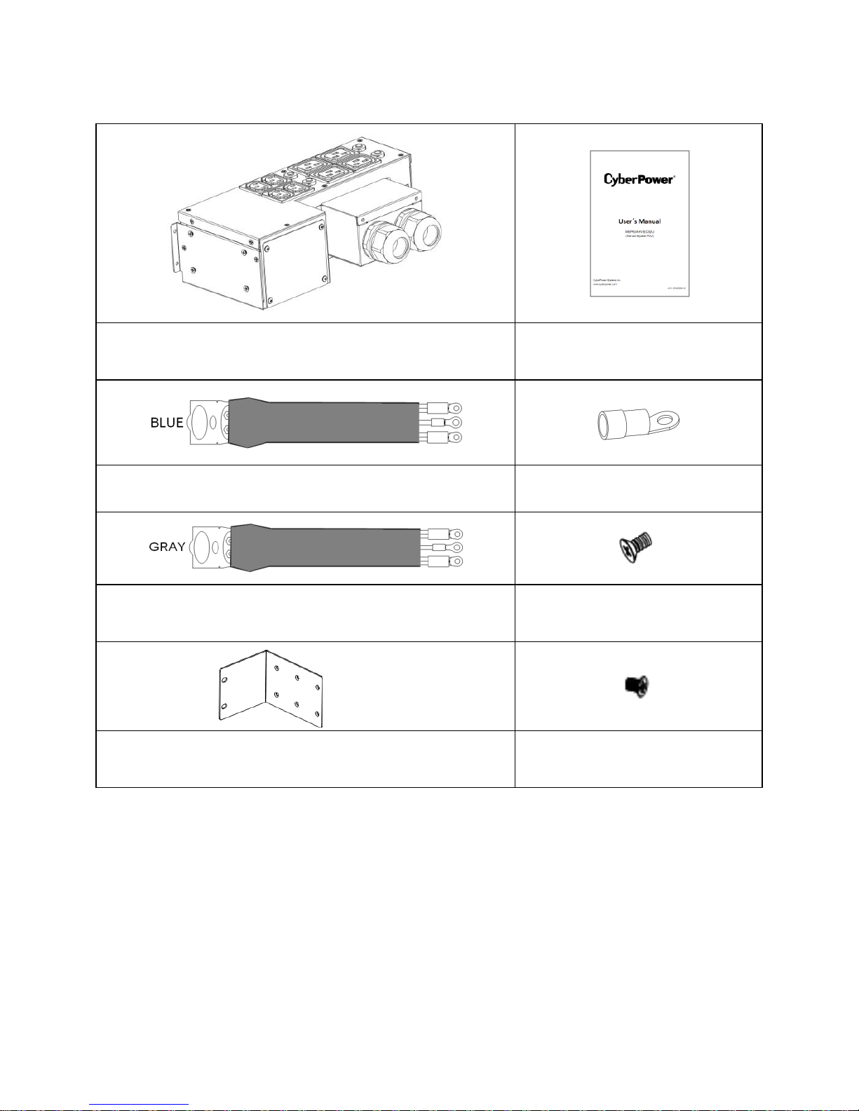
*The Below table only for OLS6000ERT6UM/OLS10000ERT6UM
Manual Bypass PDU Contains:
Manual Bypass PDU
Manual Bypass PDU User’s
Manual
UPS Input Cable(BLUE)
Terminal
UPS Output Cable(GRAY)
Flat Head Screws:
M4X8L*8PC
Rackmount Ears*2PCS
Round Head Screws:
M3X6L*4PC
***Manual Bypass PDU installed and used please refer to the User’s Manual of
Manual Bypass PDU.
CAUTION! Inspect the appearance of the UPS to see if there is any damage during
transportation. Do not turn on the unit and notify the carrier and dealer immediately if
there is any damage or lacking of some parts.
 Loading...