

Page 1

Userˊs Manual
OLS6000ERT6U
OLS10000ERT6U
OLS6000ERT6UM
OLS10000ERT6UM
CyberPower Systems Inc.
www.cyberpower.com
K01-C000250-02
Page 2

CONTENT:
1. Safety ..............................................................................................................1
1.1. Installation ..................................................................................................1
1.2. Operation ....................................................................................................1
1.3. Maintenance, Servicing and Faults .............................................................2
1.4. Transport ....................................................................................................3
1.5. Storage ....................................................................................................... 3
1.6. Standards ...................................................................................................3
2. Description of Commonly Used Symbols ....................................................4
3. Introduction ....................................................................................................4
3.1. Feature .......................................................................................................5
3.2. Electrical Specifications .............................................................................. 6
3.3. Operating Environment ...............................................................................7
3.4. Dimensions and Weights ................................................................ ............7
4. Unpacking .......................................................................................................8
5. Hardware Installation ................................................................................... 11
5.1. Rackmount Installation ............................................................................. 11
5.2. Vertical/Tower Installation ......................................................................... 13
6. Electrical Installation ................................................................................... 16
6.1. Power Wires Installation ........................................................................... 16
6.2. Operating Procedure for Connecting with the Battery module .................. 19
6.3. EPO Connection ....................................................................................... 20
7. Operation ................................................................ ...................................... 21
7.1. Display Panel ............................................................................................ 21
7.2. Turning On and Turning Off UPS .............................................................. 23
7.3. LCD Operation .......................................................................................... 24
8. Special Function .......................................................................................... 29
8.1. ECO Function ........................................................................................... 29
8.2. Converter Function ................................................................................... 29
8.3. Parallel Function ....................................................................................... 30
9. Trouble Shooting ......................................................................................... 34
9.1. Trouble Shooting According To Warning Indication .................................. 34
9.2. Trouble Shooting According To Fault Indication ....................................... 36
9.3. Trouble Shooting In Else Cases ............................................................... 37
Page 3

10. Battery Maintenance .................................................................................. 38
11. Communication Port .................................................................................... 39
11.1. USB Interface ......................................................................................... 39
11.2. RS232 Interface ..................................................................................... 39
11.3. Intelligent slot ......................................................................................... 39
Page 4

1
1. Safety
Please read carefully the following user manual and the safety instructions
before installing the unit or using the unit!
1.1. Installation
This is permanently connected equipment, and it must be installed by qualified
maintenance personnel.
Condensation may occur if the UPS is moved directly from a cold to a warm
environment. The UPS must be absolutely dry before being installed. Please
allow an acclimatization time of at least two hours.
Do not install the UPS near water or in damp environment.
Do not install the UPS where it would be exposed to direct sunlight or near heat.
Do not connect appliances or items of equipment which would overload the UPS
(e.g. laser printers, etc.) to the UPS output.
Do not block ventilation openings in the UPS’s housing. Ensure allow at least
0.5m of space on front and rear of the UPS.
Place cables in such a way that no one can step on or trip over them.
Connect UPS with the earth reliably before connecting to the building wiring
terminal, and external battery source must also be earthed.
An integral single emergency switching device which prevents further supply to
the load by the UPS in any mode of operation should be provided in the building
wiring installation.
An appropriate disconnect device as short-circuit backup protection should be
provided in the building wiring installation.
The equipment is powered by two sources: the mains source, the internal
battery or the external battery source.
With the installation of the equipment, the sum of the leakage current of the UPS
and the connected load does not exceed 5% of rated value of input current.
1.2. Operation
Do not disconnect the main cable on the UPS or the building wiring terminals
during operation since this would remove the protective earth from the UPS and
all connected loads.
The UPS output terminal block may still be electrically lived even if the UPS is
Page 5

2
not connected to the building wiring terminal, for there is internal current source
(batteries).
In order to fully disconnect the UPS, first turn the input breaker in the "OFF"
position, then disconnect the mains lead.
Indiscriminate operation of switches may cause output loss or damage to
equipment. Refer to instruction before conducting any control.
While the UPS work as a parallel system, the external parallel cable should be
reinforced insulation.
Ensure that no liquid or other foreign objects can enter the UPS.
1.3. Maintenance, Servicing and Faults
Do not remove the enclosure since the UPS operates with hazardous voltages.
It is to be serviced only by qualified maintenance personnel.
Caution! Risk of electric shock. Even after the unit is disconnected from the
mains power supply (building wiring terminal) components inside the UPS are
still connected to the battery which are potentially dangerous.
Before carrying out any kind of service or maintenance, isolate UPS and
disconnect the batteries. Verify that no current is present and no hazardous
voltage exists in the capacitor or BUS capacitor.
Batteries must be replaced only by qualified personnel.
Batteries have a high short-circuit current and pose a risk of shock. Take all
precautionary measures specified below and any other necessary measures
when working with batteries:
─ remove all jewellery, wristwatches, rings and other metal objects
─ use only tools with insulated grips and handles.
When changing batteries, replace with the same quantity and the same type of
batteries.
Do not attempt to dispose of batteries by burning them. It could cause explosion.
The UPS may be connected to Battery pack. Proper disposal of batteries is
required. Refer to your local codes for disposal requirements.
Do not open or destroy batteries. Effluent electrolyte can cause injury to the skin
and eyes. It may be toxic.
Replace the fuse only by a fuse of the same type and of the same spec in order
to avoid fire hazards.
Page 6

3
1.4. Transport
Please transport the UPS only in the original packaging to protect against shock
and impact.
1.5. Storage
The UPS must be stockpiled in the room where is ventilated and dry.
1.6. Standards
* Safety
IEC/EN 62040-1
* EMI
Conducted Emission................................:IEC/EN 62040-2
Category C3
Radiated Emission...................................:IEC/EN 62040-2
Category C3
*EMS
ESD....................................................... ..:IEC/EN 61000-4-2
Level 3
RS............................................................:IEC/EN 61000-4-3
Level 3
EFT..........................................................:IEC/EN 61000-4-4
Level 4
SURGE....................................................:IEC/EN 61000-4-5
Level 4
Low Frequency Signals............................:IEC/EN 61000-2-2
Warning: This is a product for commercial and industrial application in the
second environment-installation restrictions or additional measures may be
needed to prevent disturbances.
Page 7
4
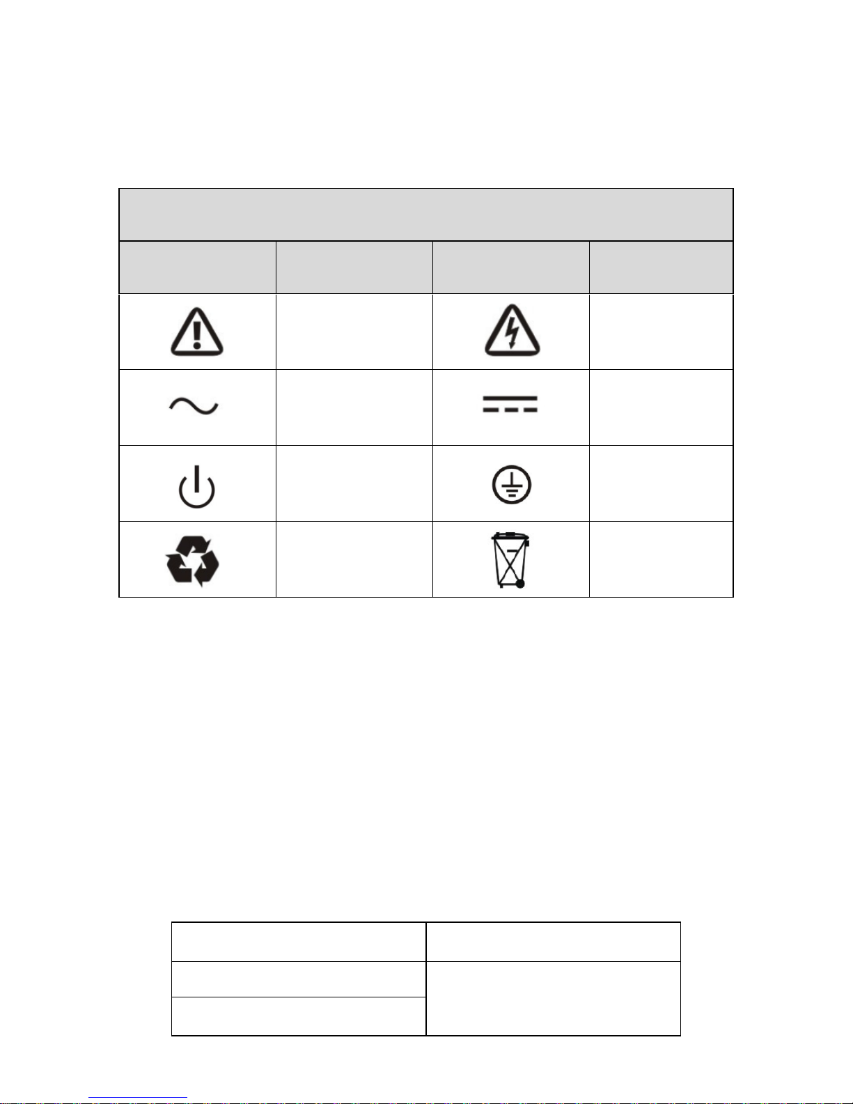
2. Description of Commonly Used Symbols
Some or all of the following symbols may be used in this manual. It is advisable to
familiarize yourself with them and understand their meaning:
3. Introduction
This On-Line series is an uninterruptible power supply incorporating
double-converter technology. It provides perfect protection specifically for computer
equipments, communication servers, and data centers.
The double-converter principle eliminates all mains power disturbances. A rectifier
converts the alternating current from the mains power to direct current. On the
basis of this DC voltage, the inverter generates an AC sinusoidal voltage, which
constantly supplies the loads. In the event of power failure, the maintenance-free
batteries power the inverter.
This manual covers the UPS listed as follows.
Mode NO.
Type
OLS6000ERT6U(M)
Standard
OLS6000ERT6U(M)
Symbol and Explanation
Symbol
Explanation
Symbol
Explanation
Alert you to pay
special attention
Caution of high
voltage
Alternating current
source(AC)
Direct current
source(DC)
Turn on or turn off
the UPS
Protective
ground
Recycle
Do not dispose
with ordinary
trash
Page 8
5
3.1. Feature
This series UPS is a new generation of UPS, which provides the outstanding
reliability, and most cost-performance ratio in the industrial. Following benefit the
product has:
True online double-conversion technology with high power density, frequency
independence and generator compatibility.
High input power factor ≥0.99,overall high efficiency ≥ 92%, save power
and wiring expense. Low input current distortion, avoid power pollution.
Output power factor is 0.9, perfect output sine waveform, suitable almost all
critical equipment.
Outstanding adaptability to the worst mains input condition. Extra wide input
voltage, frequency range and waveform, avoid excessive dissipating limited
battery energy.
N+X parallel redundancy to increase the reliability and flexibility. Number of
parallel operating UPS is up to 4.
ECO mode with high efficiency ≥96%, save power expense for user.
Start-able without battery.
Automatically select charging current through the external Battery Type and
external battery pack setting.
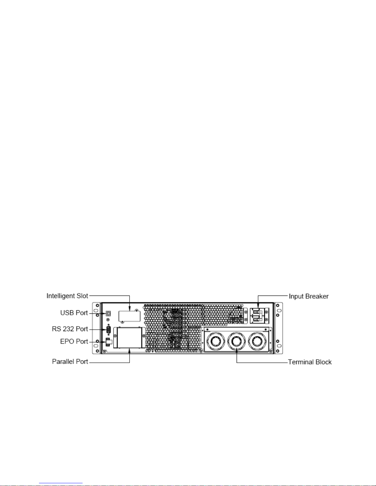
Fig.3-1 The rear view of OLS6000/10000ERT6U(M) Power module
Page 9
6
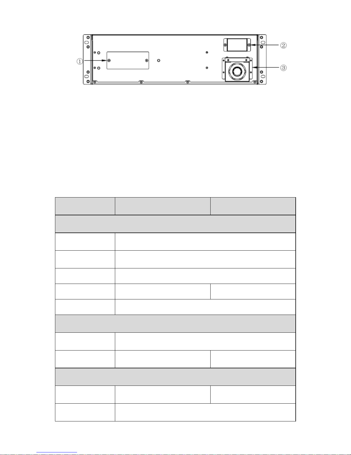
Fig.3-2 The rear view of OLS6000/10000ERT6U(M) Battery module
① Fuse: Replaceable fuse is accessible from the rear panel. It must be done by
qualified personnel.
② Output Connector: Use this output connector to connect the Battery module
and the Power module.
③ Battery Input Terminal Block: Use this input Terminal Block to daisy chain the
next Battery module.
3.2. Electrical Specifications
Model
OLS6000ERT6U(M)
OLS10000ERT6U(M)
Input
Phase
Single
Voltage Rage
110~276Vac (Depends on load level)
Frequency Rage
50/60±10%Hz
Rated Current
36A
55A
Power Factor
≥0.99 @ full load
Battery
Rated Voltage
240Vdc
Rated Current
28A
47A
Output
Power Rating
6kVA/5.4kW
10kVA/9kW
Voltage*
208/220/230/240Vac
Page 10

7
Frequency
Synchronized 50/60×(1±10%)Hz @Line mode
50/60×(1±0.1%)Hz @Battery mode
Wave Form
sine
Load Type
PF 0.5~1, lagging
THDV
≤ 2% @ full linear load;≤5% @ full nonlinear load
Over Load**
Line mode:
10 min 105%~125%
1 min 125%~150%
10 s 150%~170%
100ms >170%
Battery mode:
2 min 105%~125%
30 s 125%~150%
100ms >150%
*The load capacity would be derated to 90% automatically when the output voltage
is adjusted to 208Vac.
**The overload capacity would be derated automatically in Line mode while the
circumstance temperature is larger than 35 degree.
3.3. Operating Environment
Temperature
Humidity
Altitude
Storage
0℃~40℃
<95%
<1000m
-15℃~50℃
Note: The load capacity should be derated 1% every 100m heightened on the basis
of 1000m.
3.4. Dimensions and Weights
Model
Dimensions
W×H×D(mm)
Net Weight(kg)
OLS6000ERT6U
438*261*680
72.5
OLS10000ERT6U
438*261*680
86
OLS6000ERT6UM
438*261*821
75.1
OLS10000ERT6UM
438*261*821
88.6
Page 11
8
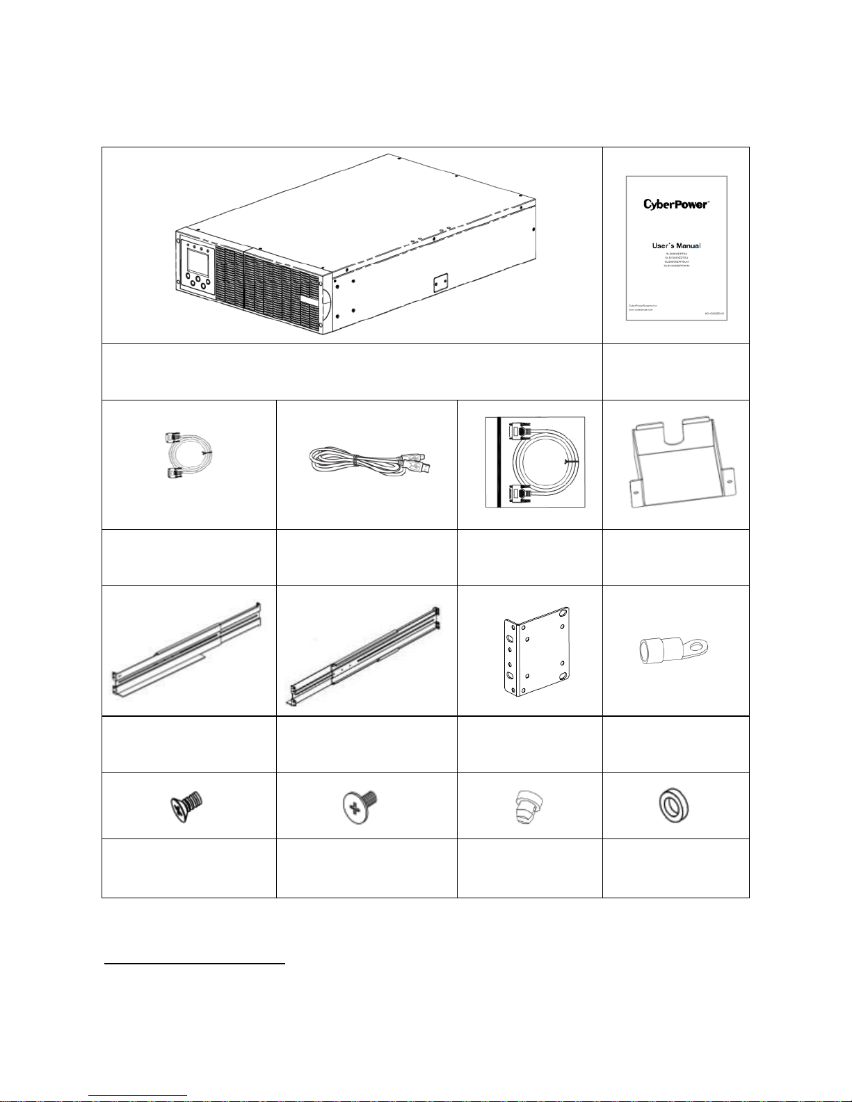
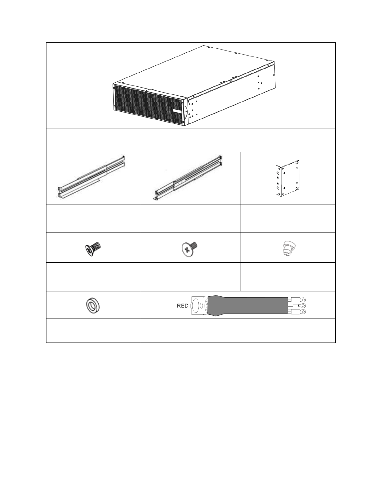
4. Unpacking
Power Module Contains:
Power Module
Power Module
User’s Manual
RS232 Cable
(optional)
USB Communication
Cable
Parallel Cable
Parallel Port
Cover Plate
Rackmount Left Rail
Rackmount Right Rail
Rackmount Ears
(Stands)*2PCS
Terminal*11PCS
Flat Head Screws:
M4X8L*8PCS
Pan Head Screws:
M5X12L*13PCS
Screw Hole Dust
Covers*8PCS
Plastic Washers
*8PCS
*PowerPanel® Personal Edition software is available on our website. Please visit
www.cyberpower.com and go to the Software Section for free download.
Page 12
9
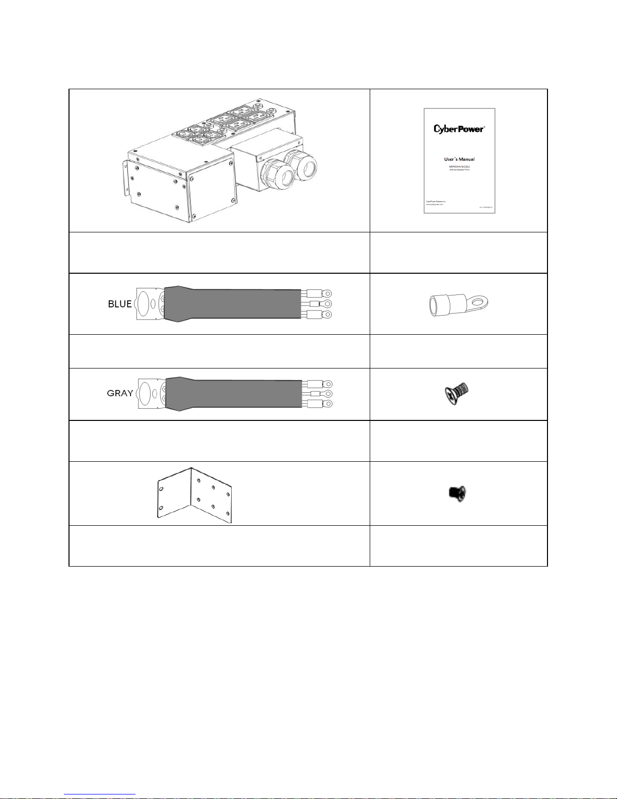
Battery Module Contains:
Battery Module
Rackmount Left Rail
Rackmount Right Rail
Rackmount Ears
(Stands)*2PCS
Flat Head Screws:
M4X8L*8PCS
Pan Head Screws:
M5X12L*13PCS
Screw Hole Dust
covers*8PCS
Plastic Washers*8PCS
Battery Cable(RED)
Page 13
10
*The Below table only for OLS6000ERT6UM/OLS10000ERT6UM
Manual Bypass PDU Contains:
Manual Bypass PDU
Manual Bypass PDU User’s
Manual
UPS Input Cable(BLUE)
Terminal
UPS Output Cable(GRAY)
Flat Head Screws:
M4X8L*8PC
Rackmount Ears*2PCS
Round Head Screws:
M3X6L*4PC
***Manual Bypass PDU installed and used please refer to the User’s Manual of
Manual Bypass PDU.
CAUTION! Inspect the appearance of the UPS to see if there is any damage during
transportation. Do not turn on the unit and notify the carrier and dealer immediately if
there is any damage or lacking of some parts.
Page 14

11
5. Hardware Installation
CAUTION! To prevent the risk of fire or electric shock, only use the supplied
hardware to attach the mounting brackets.
5.1. Rackmount Installation
UPS systems can be mounted in a rackmount or vertical tower orientation. This
versatility is especially important to growing organizations with changing needs that
value having the option to position a UPS on a floor or in a rackmount system. Please
follow the instructions below for the respective mounting methods.
Step1.Rackmount ears installation:
1) Attach the two rackmount ears to the Power module using the provided screws
M4X8L*8pcs.
2) Insert dust cover into the rackmount ear screw holes that are not being used.
Page 15

12
Step2.Rackmount rails installation:
1) The rails adjust to mount in 48-cm
(19-inch) panel racks from 52 to 91.5cm
(20.5 to 36 inches) deep. Select the
proper holes in the rack for positioning the
Power module in the rack. The Power
module takes up position 1 through
position 9.
2) Attach the rackmount rail to your rack with
two M5X12L screws and two plastic
washers at the front of the rack. (Located
in position 1 & position 6) Do not tighten
the screws. Adjust the rail size on the rail
assembly of your rack. Secure the rail to
the rear of the rack with two M5X12L
screws and two plastic washers. Tighten all screws at the front and rear of the
rail. Once completed, perform the same steps for assembling the other
rackmount rail.
Page 16

13
Step3.Install the Power module on the rack:
1) Place the Power module on a flat stable surface with the front of the unit facing
toward you. Secure the Power module to your rack with four M5X12L screws
at the front of the rack. (Located in position 2 & position 8).
2) Once completed, perform the same steps for the Battery module.
CAUTION! The Battery module must be installed below the Power module.
5.2. Vertical/Tower Installation
Step1.Rotate the multifunction LCD module:
1) Unscrew the right panel of the Power module. Separate the right panel from
Power module.
Page 17

14
2) Unscrew the left panel of the Power module. Separate the left panel from
Power module.
3) Rotate the LCD module to the left. Reinstall it for a tower configuration .
4) Last tighten the screws to fix the left panel and the right panel.
Page 18

15
Step2.Attach the base stands:
1) Tighten the screws (M5X12*4pcs) of the base stands (rackmount ears) onto
the bottom of Power module and Battery module.
2) Insert dust cover into the rackmount ear screw holes that are not being used.
Page 19

16
6. Electrical Installation
6.1. Power Wires Installation
The system must be installed and wired only by qualified electricians in
accordance with applicable safety regulations!
For safety, please cut off the mains power switch before installation!
When installing the electrical wiring, please note the nominal amperage of your
incoming feeder.
Use cable cross section and protective device specification:
Model
OLS6000ERT6U(M)
OLS10000ERT6U(M)
Protective earthing conductor
Min cross section
6mm²
(UL101510AWG)
10mm²
(UL1015 8AWG)
Input L, N, G
Min conductor cross section
6mm²
(1015 10AWG)
10mm²
(UL1015 8AWG)
Input breaker
40A/250Vac
63A/250Vac
Output L,N,
Min conductor cross section
6mm²
(1015 10AWG)
10mm²
(UL1015 8AWG)
Torque for fixing above terminals
3.95~4.97Nm
(35~44 1b in)
1) It is suggested to install an external isolating device against current backfeed
between mains input and Power module. After the device is installed, it must
add a warning label with the following wording or the equivalent on the external
AC contactor: RISK OF VOLTAGE BACKFEED. Isolate the Power module
before operating on this circuit, then check for hazardous voltage between all
terminals.
AC Contactor
Coil Remotes Swith
Main
Input
Input Main
Breaker
L
N
UPS
Fig.6-1 Typical external isolating device installation
Page 20

17
2) No matter the Power module is connected to the mains power or not, the
output of the Power module may be electrically live. The parts inside the unit
may still have hazardous voltage after turning off the Power module. To make
the Power module have no output, turn off the Power module, and cut off the
mains power supply, wait the Power module shut down completely, finally cut
off the battery connection.
3) Open the terminal block cover located on the rear panel of Power module,
please refer to the appearance diagram.
4) For OLS6000ERT6U(M), it is recommended to select the UL1015
10AWG/6mm² or other insulated wire which complies with AWG Standard for
the Power module input and output wirings.
5) For OLS10000ERT6U(M), it is recommended to select the UL1015
8AWG/10mm² or other insulated wire which complies with AWG Standard for
the Power module input and output wirings.
6) Ensure the capacity of mains power supply. Do not use the wall receptacle as
the input power source for the Power module, as its rated current is less than
the Power module’s maximum input current. Otherwise the receptacle may be
burned and destroyed.
7) The protective earth ground wire should be installed first according to the
following diagram. It is better to use green wire or green wire with yellow ribbon
wire.
8) Connect other input and output wires to the corresponding input and output
terminals according to the following diagram.
9) Operating procedure for connecting with the Battery module by following the
chapter 6.2.
Page 21

18
10) It is requested to use the accessorial terminal splices which can be compacted
on the wires tightly, to ensure the connection between the wires and the
terminal block is reliable.
Fig.6-2 Input and output terminal block wiring diagram
Important notes:
If the Power module is used in single mode, the output must be connected to sL and
sN.
If the Power module is used in parallel mode, the output must be connected to pL
and pN.
11) Install an output breaker between the output terminal of Power module and the
load, and the breaker should with leakage current protective function if
necessary.
12) Turn off all the loads first before connecting the load with the Power module,
then perform the connection and finally turn on the loads one by one.
13) After completing the installation, please check the wires to make sure all were
connected correctly and tightly.
14) Suggest charging the batteries for 8 hours before use. After Installation, turn
on the mains power switch and turn the input breaker in the "ON" position, the
Power module will charge the batteries automatically. It can also use the
Power module immediately without charging the batteries, but the backup time
may be less than the standard value.
15) If it is necessary to connect the inductance load such as a monitor or a laser
Input Ground
Input N
Input L
Battery +
Battery Battery Ground
Parallel Mode Output L
Output Ground
Single Mode Output L
Parallel Mode Output N
Single Mode Output N
Page 22

19
printer to the Power module, the start-up power should be used for calculating
the capacity of the Power module, as its start-up power consumption is too big
to make the Power module which capacity is small fail easily.
6.2. Operating Procedure for Connecting with the
Battery module
1) Loosen the screws to remove the Terminal Block Cover located on the rear
panel of Power module.
2) Connect the Battery Cable to the Power module and ensure the polarity is
right.
3) Loosen the screws to remove the Output Connector Cover of Battery module.
Page 23

20
4) Connect the Battery Cable to the Battery module. Once completed, retighten
the Block Cover.
6.3. EPO Connection
EPO (Emergency power off): when the emergency occurs, such as the failure of
load, the UPS can cut off the output at once by operating the EPO port manually.
The connection:
Normally the EPO connector is closed with a wire on the rear panel(Fig.6-4), which
is supplied in the accessory. Once the connector is open, the UPS would stop the
output and enter EPO status (Fig.6-3).
Fig.6-3 Enable the EPO status Fig.6-4 Disable the EPO status
To recover to normal status, first EPO connector should be closed (Fig.6-4), and
enter LCD menu (illustrated in the chapter of 7.3) to clear EPO status, then UPS
would stop alarm and recover to Bypass model. And UPS needs be turned on by
manual operation.
Page 24

21
7. Operation
7.1. Display Panel
The UPS has a five-button, dot matrix LCD with white text and a blue background.
Besides the LCD, the UPS has four colorized LED to provide more convenient
information.
Fig.7-1 LCD Panel
Control button functions:
The Button
Function
illustration
Power on
When the unit is no power and has connected with
battery, press this button for >200ms&<1s to power on
Turn on
When the unit is powered on and is in Bypass mode,
press this button more than 1s to turn on
Turn off
When the unit has been turned on, press this button
more than 3s to turn off
Enter
Press this button more than 200ms to confirm current
selection or enter the current selection window
ESC
Exit
Press this button more than 200ms to cancel current
selection and return to previous menu.
Page 25

22
UP
Press this button more than 200ms to move the focus to
the up menu
Down
Press this button for more than 200ms to move the focus
to the down menu
LED definition:
UPS state
Normal
(Green LED)
BATTERY
(Yellow LED)
BYPASS
(Yellow LED)
FAULT
(Red LED)
Bypass mode without
output
★
□
Bypass mode with output
〇
□
Line mode 〇
□
Battery mode
〇 〇
□
ECO mode 〇
〇
□
Battery test mode
※ ※ ※
※
Turn on ※ ※
※
※
Fault mode
□
〇
Warning mode
□ □ □
★
Note:〇: Lightened constantly; ※: #1-#4 Lightened circularly;
★: Flashing; □: Depended on the fault/warning status or other status
Alarm definition:
UPS condition
Buzzer status
Fault active
Continuous
Warning active
Beep every second
Battery mode
Beep every 4 seconds, if battery low, buzzer Beep every second
Bypass mode
Beep every 2 minutes
Overload
Beep twice every second
Page 26

23
The UPS provides useful information about UPS itself, load status, battery, events,
identification, and settings through the front panel display.
During powering on, the LCD would display the CyberPower logo for several
seconds and then enter to the default page which shows the UPS status summary.
On the UPS status screen it provides the following information:
Status summary, including mode, load, battery and utility
Alarm status, if any is present.
Fault status, if any is present.
Output parameter, including output voltage, current and frequency.
Input parameter, including input voltage and frequency.
Bypass parameter, including bypass voltage and frequency.
Power parameter, including output VA and watt.
Battery parameter, including battery capacity, voltage and remain time.
7.2. Turning On and Turning Off UPS
Attention: The UPS could only be turning on while connecting with the mains at
the first time.
Attention: Please switch off the connected loads first before turning on the UPS,
and switch on the loads one by one after the UPS is turned on. Switch off all of the
connected loads before turning off the UPS.
Turning on UPS with mains:
1) Check all the connection is correct, and the DC voltage of battery pack output
is right.
1) Set input breaker in "ON" position. At this time the fan begins to rotate, LCD
will show "CyberPower". Then LCD will show the default UPS status summary
screen after UPS finishing self-test.
2) By pressing button continuously for more than 1 second,the buzzer will
beep for 1s, UPS starts to turn on.
3) A few seconds later, the UPS turns into Line mode. If the mains power is
abnormal, the UPS will transfer to Battery mode without output interruption of
the UPS.
Turning on UPS without mains:
2) Check all the connection is correct, and the DC voltage of battery pack output
is right.
3) By pressing button continuously for >200ms&<1s, the UPS would be
Page 27

24
powered on. At this time the fan begins to rotate, LCD will show "CyberPower".
Then LCD will show the default UPS status summary screen after UPS
finishing self-test.
4) By pressing button continuously for more than 1s,the buzzer will beep for
1s, UPS starts to turn on.
5) A few seconds later, the UPS turns into Battery mode. If the mains power
comes back, the UPS will transfer to Line mode without output interruption of
the UPS.
Turning off UPS with mains:
1) To turn off the inverter of UPS by pressing button continuously for more
than 3s and the buzzer will beep for 3s. The UPS will turn into Bypass mode at
once.
2) When completing the above action, UPS output voltage is still present. In order
to cut off the UPS output, simply cut off the mains power supply. A few
seconds later, LCD display shuts down and no output voltage is available from
the UPS output terminal.
Turning off UPS without mains:
1) To power off the UPS by pressing button continuously for more than 3s,
and the buzzer will beep 3s. The UPS will cut off the output at once.
2) A few seconds later, LCD shuts down and no voltage is available from the UPS
output.
7.3. LCD Operation
Except the default UPS status summary screen, the user could get more useful
information about UPS current status, old events which ever occurred, UPS own
identification, and could change the settings to fit the user own requirements,
optimize the function of UPS.
The status screen:
In the UPS status screen, when pressing or >200ms the detailed
information about UPS information that include alarm, fault output, input, bypass,
load and battery parameter would be shown, See Fig.7-2.
when pressing > 200ms the main menu would be shown. In fault or alarm
screen, when pressing > 200ms, the other alarm or fault would be shown by
pressing or >200ms, and press >200ms the display would return to
status screen. The main menu includes four branches: UPS control menu, setting
Page 28

25
menu, event menu and identification menu. See Fig.7-3.
Fig.7-2 UPS status menu
Load: 60 %
I/P Volt: 223.5 V
Bat Volt: 260 V
Status:Line
Output parameter
Volt: 230 V
Curr: 14.5 A
Freq: 50.0 Hz
Input parameter
Volt: 223.5 V
Freq: 50.1 Hz
Bypass parameter
Volt: 223.5V
Freq: 50.1Hz
Power parameter
KW: 3.6
KVA:3.6
Bat parameter
Bat Volt: 260V
Capacity: 95 %
Rmn time 14 Min
Cyberpower
Alarm
0002:12:00:00
Overload
1/10
Fault
0003:12:00:00
Over tempearture
1/5
Down>200mS Up>200mS
Down>200mS Up>200mS
Down>200mS Up>200mS
Down>200mS Up>200mS
Down>200mS Up>200mS
Down>200mS Up>200mS
Down>200mS
Up>200mS
Alarm
0002:12:20:00
Line site
2/10
Enter>200mS
ESC>200mS
Alarm
0002:12:00:00
Overload
1/10
Up>200mS Down>200mS
Fault
0003:12:00:00
Over tempearture
1/5
Enter>200mS
ESC>200mS
Cable loss
0003:12:00:00
Over tempearture
2/5
Up>200mS
Down>200mS
Up>200mS
Down>200mS
.
.
.
Up>200mS
Down>200mS
Control
Setting
Events
ID
ESC>200mS
ESC>200mS
Page 29

26
Fig.7-3 Main menu
Buzzer mute
Clr EPO status
Battery test
Single UPS off
Buzzer mute
Yes
No
Battery test
Yes
No
Clr EPO status
Yes
No
Single UPS off
Yes
No
Control
Setting
Events
ID
Events&alarms
Fault
Clear all events
Clear all faults
Event
0001:12:00:00
Utility abnormal
1/10
Alarm
0002:12:00:00
Overload
1/10
Fault
0003:12:00:00
Over tempearture
1/5
Clear all events
Yes
No
Clear all faults
Yes
No
Type/model
Serial number
Rating
Firmware version
Type/model
OLS 6000ERT6U
Long model
Serial number
************
Rating
IP:230Vac/50Hz
OP:230Vac/50Hz
Power:6kVA/5.4kW
Firmware version
Ver:0.0.1
Please input
Password
****
Sub setting...
Page 30

27
The control menu:
By pressing , enter the menu of "Control". The display would enter the next
control menu screen.
1) Buzzer mute
2) Battery test: is one command to control all UPS in a parallel system to do the
battery test at the same time.
3) Clear EPO status: once EPO status is enabled, the UPS output would be cut
off. To recover to normal status, first EPO connector should be closed, and
enter this menu to clear EPO status, then UPS would stop alarm and recover
to Bypass model. And UPS needs be turned on by manual operation.
4) Single UPS off: is one command to turn off one UPS which is operated
currently in parallel system, and other UPS continue working to supply the load
in the parallel system.
The setting menu:
Please contact your local distributor for further information before using the settings.
Some settings would change the specification, and some settings would enable or
disable some functions. The unsuitable option set by user may result in potential
failures or protecting function loss, even directly damage the load, battery or
UPS.The most of settings could only be done while UPS is in Bypass mode.
Submenu item
Optional Values
Default Value
User password*
enabled/disabled
enabled
Audio alarm
enabled/disabled
enabled
Site wiring fault alarm
enabled/disabled
enabled
Ambient temperature warning
enabled/disabled
enabled
DC start
enabled/disabled
enabled
Auto Restart
enabled/disabled
enabled
Automatic overload restart
enabled/disabled
enabled
Auto Bypass
enabled/disabled
enabled
Page 31

28
Short circuit clearance
enabled/disabled
disabled
Power strategy**
normal/ECO/converter
normal
Rated output voltage
208/220/230/240V
230V
Output frequency
50/60Hz
50Hz
Bypass voltage low range
10%,15%,20%
15%
Bypass voltage high range
10%,15%
10%
Bypass frequency range
1%~10%
10%
ECO voltage range
10%,15%
10%
ECO frequency range
1%~10%
5%
Ext. Bat Type***
Standard/Customized
Standard
Ext. Bat Pack ****
1Packs~15Packs
0 Packs
Automatic battery tests period
0~45days
7days
Set running time
Day: hour: minute: second
0000:0000:00~9999:23:59:59
Running time
Restore default setting
Yes/NO
*Password is AAAA when enabled.
**Read the chapter of 8.1 and 8.2, before using ECO or converter function. UPS
need shut down, if change work mode from converter to others.
***Large current Charging when Ext. Bat Type is "Customized".
****Small current Charging when Ext. Bat Pack≤1 Packs. Large current Charging
when Ext. Bat Pack >1 Packs.
Page 32

29
8. Special Function
The series UPS has some special functions, which could satisfy some special
application of user. And the functions have own features, please contact your local
distributor for further information before using the function.
8.1. ECO Function
Brief introduction of ECO function:
If ECO function is set to enable, after the UPS is turned on, the power used by the
load is directly supplied from the mains power via internal filter while the utility
power is in normal range, so the economy mode could be gained in ECO mode.
Once the mains power is loss or abnormal, the UPS would transfer to Line mode or
Battery mode and the load is supplied continuously.
The great virtue is overall high efficiency≥96% of UPS, to save power for user.
But the disadvantage is:
1) The load can’t be protected as well as in Line mode, for the load is directly
supplied from the mains;
2) The transfer time of UPS output from ECO mode to Battery mode is about
10ms.
So the function is not suitable to some sensitive loads, and the region where the
mains power is unstable.
Set the function:
The function could be enabled through the LCD setting in Bypass mode. Enter the
power strategy setting menu by following chapter of 7.3.
8.2. Converter Function
Brief introduction of Converter function:
In converter mode, the UPS would free run with fixed output frequency (50Hz or
60Hz). Once the mains power is loss or abnormal, the UPS would transfer to
Battery mode and the load is supplied continuously.
The great virtue is the output frequency is fixed, which is required by some very
sensitive loads. But the disadvantage is the load capacity of UPS should be
derated to 60% in converter mode.
Set the function:
The function could be enabled through the LCD setting in Bypass mode. Enter the
Page 33

30
power strategy setting menu by following chapter of 7.3.
8.3. Parallel Function
Brief introduction of the redundancy:
N+X is currently the most reliable power supply structure. N represents the
minimum UPS number that the total load needs, X represents the redundant UPS
number, i.e. the fault UPS number that the system can handle simultaneously.
When the X is larger, the reliability of the power system is higher. For occasions
where reliability is highly depended on, N+X is the optimal mode.
As long as the UPS is equipped with parallel cables, up to 4 UPS can be connected
in parallel to realize output power sharing and power redundancy.
How to install a new parallel UPS system:
1) Before installing a new parallel UPS system, user need to prepare input and
output wires, input and output breaker, main maintenance bypass switch.
2) Remove the cover plate of the parallel port on the UPS, connect each UPS
one by one with the parallel cable, and re-screw the parallel port cover which is
supplied in the accessories.
Fig.8-1 Parallel cable connect diagram
3) Strictly follow the chapter of 6.1, the wiring requirement of single UPS to
perform the wiring of each UPS.
Page 34

31
4) Connect the output wires of each UPS to an output breaker panel, and connect
each output breaker to a main output breaker and then to the loads.
5) CAUTION: Each UPS needs an independent battery pack.
6) Please refer to the wiring diagram in the following diagram.
sN
L
N
BATTERY
+
-
sL
pL
pN
sN
INPUT
L
N
BATTERY
+
-
OUTPUT
sL
pL
pN
1# Battery pack
2# Battery pack
UPS1 Input
Breaker
UPS2 Input
Breaker
Main Input Ground
To Main Input
Breaker
UPS2 Output
Breaker
UPS1 Output
Breaker
Main Output Ground
To Main
Output Breaker
OUTPUT
INPUT
Fig.8-2 Input and output terminal block wiring diagram
Page 35

32
TO LOAD
TO UTILITY
Main Maintenance
Bypass Switch
Main Input
Breaker
Main Output
Breaker
Maintenance Bypass for Parallel
UPS2 Output Breaker
UPS1 Output Breaker
UPS3 Output Breaker
UPS1 Input Breaker
UPS2 Input Breaker
UPS3 Input Breaker
Fig.8-3 Parallel installation diagram
7) The distance between the UPS in parallel and the breaker panel is required to
be less than 20 meters. The difference between the wires of input and output
of the UPS is required to be less than 20%.
8) Do not switch on the output breaker of each UPS, switch on the input breaker
of the each UPS, the UPS should work in bypass with output, observe their
display to check if there are any warning or fault information, measure the
output voltage of each UPS separately to check if the voltage difference
between them is less than 1V. If the difference is more than 1V, check the
wiring.
9) Press the button of one UPS, each UPS would start to turn on, all the
UPS would transfer to the Line mode together. Measure the output voltage of
each UPS separately to check if the voltage difference between them is less
Page 36

33
than 0.5V. If the difference is more than 0.5V, the UPS need to be regulated.
10) Press the button of one UPS, each UPS would start to turn off and
transfer to the Bypass mode, switch on the output breaker of each UPS to
parallel all the output of UPS together.
11) Press the button of one UPS, each UPS would start to turn on , after
turning on, the UPS should work parallel in the Line mod
How to join a new UPS to a parallel system:
1) First the parallel system must be installed one main maintenance bypass
switch.
2) Regulate the output voltage of the new UPS separately: check if the output
voltage difference between the new UPS and the parallel system is less than
0.5V.
3) Ensure the bypass of the parallel system is normal and the bypass setting is
"enable", Press the button of one UPS, each UPS would turn off and the
UPS system would transfer to the Bypass mode.
4) Set the main maintenance bypass switch from "UPS" to "BPS", switch off the
main output breaker and the main input breaker, the UPS would shut down.
5) Ensure the UPS shut down totally, add the new UPS and reinstall the new
UPS parallel system by following step 1) to 10) of last chapter - "How to install
a new parallel UPS system".
6) Switch on the main input breaker and the main output breaker, and set the
main maintenance bypass switch from "BPS" to "UPS", Press the button
of one UPS, each UPS would start to turn on, after turning on, the UPS should
work parallel in the Line mode.
How to remove a single UPS from a parallel system:
1) First the parallel system must be installed one main maintenance bypass
switch.
2) Ensure the bypass of the parallel system is normal and the bypass setting is
"enable", Press the button of one UPS, each UPS would turn off and the
UPS system would transfer to the Bypass mode.
3) Set the main maintenance bypass switch from "UPS" to "BPS", switch off the
main output breaker and the main input breaker, the UPS would shut down.
4) Ensure the UPS shut down totally, remove the wanted UPS and reinstall the
new UPS parallel system by following step 1) to 10) of last chapter - "How to
Page 37

34
install a new parallel system".
5) Switch on the main input breaker and the main output breaker, and set the
main maintenance bypass switch from "BPS" to "UPS", Press the button
of one UPS, each UPS would start to turn on, after turning on, the UPS should
work parallel in the Line mode.
9. Trouble Shooting
If the UPS system does not operate correctly, first check the operating information
on the LCD display. Please attempt to solve the problem using the table below. If
the problem still persists, consult your dealer.
9.1. Trouble Shooting According To Warning
Indication
Problem Displayed
Possible cause
Remedy
EPO Active
EPO connector is
open
Check the EPO connector
status
Site Fail
The Ground wire is
disconnected or Phase
and neutral conductor at
input of
Check the Ground wire status.
Reverse mains power wiring.
Battery Open
Battery is disconnected
Do the battery test to confirm.
Check the battery bank is
connected to the UPS.
Check the battery breaker is
turn on.
Battery volt low
Battery voltage is low
When audible alarm sounding
every second, battery is almost
empty.
Over load
Over load
Check the loads and remove
some non-critical loads.
Check if some loads are failed.
Fan Fail
Fan abnormal
Check if the fan is running
normally.
Charger Fail
The charge fails
Consult dealer.
Page 38

35
Battery Over Voltage
Battery voltage is
higher than normal
value
Check if the battery quantity is
right.
Over Charge
Battery is over
charged
The UPS will turn off the
charger until the battery voltage
is normal
Amb NTC abnormal
The ambient
temperature is too
high
Check the environment
ventilation.
Ambient NTC abnormal
UPS internal fault
Consult dealer.
Cable disconnect
The parallel cable is
disconnected
Check the parallel cable.
Cable loss
The parallel cable is
disconnected
Check the parallel cable.
Battery Differ
The battery packs of
some UPSs are
disconnected
Check if all the battery pack is
connected.
Line Differ
The mains input of
some UPSs is
disconnected
Check the building wiring and
input cable.
Check if the input breaker is
Work Mode Differ
There are different
power strategy setting
in parallel system
The UPSs with different power
strategy setting (Ex. one Line
mode and one Converter mode)
are forbidden to parallel.
Rate Power Differ
There are different
UPSs in parallel
system
The UPSs with different
capacity (Ex. one OLS6000E
and one OLS10000E) are
forbidden to parallel.
ECO In Para
ECO function is
enabled in parallel
system
ECO function is forbidden in
parallel system.
Fuse Open
Input fuse break
Check the input fuse status
Page 39

36
9.2. Trouble Shooting According To Fault Indication
Problem Displayed
Possible cause
Remedy
Output short
Output short circuit
Remove all the loads. Turn off the
UPS. Check if UPS output and loads
is short circuit. Ensure short circuit is
removed before turning on again.
Over load
Over load
Check the loads and remove some
non-critical loads.
Check if some loads are failed.
Neg power fail
The load is pure
inductive and capacitive
Remove some non-critical loads.
Bypass supplies the load first, ensure
there is no overload, then turn on UPS
Over temperature
Inside temperature of
UPS is too high
Check the ventilation of UPS and the
ambient temperature
Fan fail
Fan blocked or
disconnected over time
Check the fan status
Back feed
Output voltage is
returned to input
Consult dealer
DC short
Bus short
Consult dealer.
DC over
Bus over voltage
Consult dealer.
DC under
Bus under voltage
Consult dealer.
DC unbalance
Bus unbalance
Consult dealer.
DC soft fail
Bus soft start fail
Consult dealer.
Output soft fail
Output soft start fail
Consult dealer.
Output volt low
Output volt low
Consult dealer.
Output volt high
Output volt high
Consult dealer.
Page 40

37
9.3. Trouble Shooting In Else Cases
Problem
Possible cause
Remedy
No indication, no warning tone
even though system is connected
to mains power supply
No input voltage
Check the building wiring and
input cable. Check if the input
breaker is closed
BYPASS LED light up even though
the power supply is available
Inverter not
switched on
Press button to turn on
UPS.
BATTERY LED lights up, and
audible alarm sounding every 1
beep in every 4 seconds
Input voltage
and/or frequency
are out of
tolerance
Check input power source.
Check the building wiring and
input cable. Check if the input
breaker is closed.
Emergency supply period shorter
than nominal value
Batteries not fully
charged /batteries
defect
Charge the batteries for at
least 12 hours and then check
capacity.
Please have the following information at hand before calling the After-Sales Service
Department:
1) Model number, serial number
2) Date on which the problem occurred
3) LCD/LED display information, Buzzer alarm status
4) Mains power condition, load type and capacity, environment temperature,
ventilation condition
5) The information (battery capacity, quantity) of Battery pack
6) Other information for complete description of the problem
Page 41

38
10. Battery Maintenance
Battery replacement should be performed by qualified personnel.
This series UPS only requires minimal maintenance. The batteries used for
battery pack are value regulated sealed lead-acid maintenance free battery.
These models require minimal repairs. The only requirement is to charge the
UPS regularly in order to maximize the expected life of the battery. When
being connected to the utility power, whether the UPS is turned on or not, the
UPS keeps charging the batteries and also offers the protective function of
overcharging and over-discharging.
The UPS should be charged once every 4 to 6 months if it has not been used
for a long time.
In the regions of hot climates, the battery should be charged and discharged
every 2 months. The standard charging time should be at least 12 hours.
Under normal conditions, the battery life lasts 3 to 5 years. In case if the
battery is found not in good condition, earlier replacement should be made.
Battery replacement should be performed by qualified personnel.
Replace batteries with the same number and same type of batteries.
Do not replace the battery individually. All the batteries should be replaced at
the same time following the instructions of the battery supplier.
If the battery service life (3~5 years at 25°C ambient temperature) has been
exceeded, the batteries must be replaced.
Page 42

39
11. Communication Port
11.1. USB Interface
The USB port is compliance with USB 1.1 protocol for its communication software.
11.2. RS232 Interface
The RS-232 port is available for UPS monitoring, control, and firmware updates.
11.3. Intelligent slot
This series is equipped with an intelligent slot for other optional card to achieve
remote management of the UPS through internet / intranet. Please contact your
local distributor for further information.
CyberPower Systems Inc.
www.cyberpower.com
6F, No. 32, Sec. 1, Chenggong Rd., Nangang District, Taipei 115, Taiwan
Entire contents copyright© 2013 CyberPower Systems Inc., All rights reserved. Reproduction in whole or
in part without permission is prohibited. PowerPanel® Business Edition and PowerPanel® Personal
Edition are trademarks of CyberPower Systems Inc.
 Loading...